立式电机说明书
Orientail Motor 步进电机参考目录说明书

B-1212000-2001 ORIENTAL MOTOR GENERAL CATALOGGENERAL CATALOGUFK •WFeatures ·····························································B-122Standard Type ····················································B-126Geared Type ·······················································B-132List of Motor and Driver Combinations ···············B-145Setting the Step Angle ········································B-146Wiring Diagram ···················································B-147Description of Input/Output Signals ····················B-148B-1222000-2001 ORIENTAL MOTOR GENERAL CATALOGUFK •Wstepping motor angle of 0.72˚ and divides itelectrically into smaller step angles providing up to 125,000 steps per revolution.The UFK •W uses 5-phase microstepping,the most advanced stepping motor drivetechnology available. It takes the basic 5-phaseis a series of stepping motors and drivers thatcombines high-performance 5-phase microstep drivers withhigh-torque/low-vibration 5-phase stepping motors. They provide smooth and precise operation.Ⅲ5-phase Microstep Drive TechnologyThe primary feature of stepping motors is the ability to obtain precise positioning. They achieve this by rotating and stopping at step angle increments that are determined by the pole structure of the rotor and stator. Rotating in step angle increments, however,also produces changes in rotor speed and resonance at certain speeds that can increase vibration.Microstep driving provides a finer degree of control of the basic motor step angle by regulating the current sent to the motor coils,resulting in, low vibration, even at low speed.●Since the basic motor step angle (0.72˚/full step) can be divided into proportions ranging from 1/1 to 1/250, smooth operation in fine increments is possible.●T echnology that changes the motor drive current smoothly suppresses motor vibration and makes operation audibly quieter.ⅢMicrostep Resolution Up to 125,000StepsUFK •W enables step angles to be setindependently on two resolution selection switches (16 possible microstep resolutions with as many as 250 microsteps per full step). This enables two independent resolutions to be selected by using the resolution select input. Changing resolution should occur when the motor is in the stop position. This will eliminate the chance of positioning error.1.Low Vibration, Low NoiseMicrostep technology allows the step angle to be subdivided electrically.This smoothes stepped operation at low speeds and drastically improves vibration. The UFK •W uses a motor design that also helps to reduce vibration. Therefore theUFK •W is ideal for applications where vibration is aproblem.ⅢFEATURES0.51.0V i b r a t i o n V o l t a g e V p -p [V ]Speed [r/min ]2.High SpeedTheUFK •W provides low vibration at both low andhigh speeds.3.Standard Certified ProductThis product is certified under applicable standards from around the world. Also, the CE marking is implemented according to the low voltage directive. (For details on standard certified products,see Page D-16.)EASY WIRING GEAR PLC DIRECT RE -GENER -ATION SAFETY STD.PACK-AGE ACINPUTⅢ What isB-1232000-2001 ORIENTAL MOTOR GENERAL CATALOGA high-torque 5-phase stepping motor and microstep driver are combined to make high-precision positioning with open loop control possible.ⅢACCESSORIES (Sold separately)Ⅲ UFK •W SYSTEM CONFIGURATIONB-1242000-2001 ORIENTAL MOTOR GENERAL CATALOGⅢPRODUCT LINEUFK •WStandard TypeThere are two motor frame sizes available: 2.36 inches (60 mm)and 3.35 inches (85 mm) square. They can handle low-speeds,low-vibration and low-noise applications.Page B-126the model numbers.UFK •WTHGeared TypeThis series combines the UFK •W with TH gears, which providelow speed reduction ratios (3.6:1, 7.2:1, 10:1, 20:1, and 30:1)and are low backlash (25 arc minutes max.)Page B-132●Enter A (single shaft) or B (double shaft) in the within the model numbers.UFK•WPN Geared TypeThe newly developed backlash reduction feature is utilized andattains backlash below 3 arc minutes. This is a major increase in precision.Page B-132the model numbers.B-1252000-2001 ORIENTAL MOTOR GENERAL CATALOGThe motor current is easy to adjust with digital switches. No ammeter necessary.RUN:Can be adjusted the motor runningcurrent.STOP:Can be adjusted the current at motorstandstill.Switches between 1-pulse input and 2-pulse input.The UFK •W of Dedicated Drivers: Designed with User-Friendly FunctionsDriver operating status is visible at a glanceEasy to confirm I/O signals.POWER: Power input display TIM.:Excitation timing output display O.H.: Overheat output displayUse these rotary switches to set the desiredresolution from the 16 resolution levels available.See page B-146 for details.A full range of driver functions are on thefront panel.z nc mxvbWhen the level of heat within the driver reaches176°F (80°C), this function automatically switches the motor current off. The function can be set anddisabled with this switch.2.B-1262000-2001 ORIENTAL MOTOR GENERAL CATALOGUFK •W Standard TypeThe UFK •W uses 5-phase microstepping,the most advanced stepping motor drive technology available.ⅢAPPLICABLE STANDARDS AND CE MARKINGT o r q u e [N ·m ]Speed [r/min ])ⅢFEATURES●Standard TypeAvailable in two motor frame sizes of 2.36 inch (60 mm) sq. and 3.35 inch (85 mm) sq.They meet various application needs with low speed, low vibration and/or low noise.Holding Torque: 58.3 oz-in (0.42 N ·m) ϳ874 oz-in (6.3 N ·m)●High SpeedThe UFK •W provides high torque in the high speedrange.Note:●See page D-9 for more information on operating conditions of EN/IEC standards.●The EN/IEC standard certification depends on the type and installation size.For details, see Page D-16.●The products are recognized when used together.ⅢPRODUCT NUMBER CODE: UFK •Wc Array●Maximum holding torque refers to the holding torque at motor standstill when the rated current is supplied to the motor (5 phase excitation). Use this value tocompare motor torque performance. When using the motor with the dedicated driver, the driver's "Automatic Current Cutback" function at motor standstill reducesmaximum holding torque by approximately 50%.●The power source input current value represents the maximum current. (The input current varies according to the pulse frequency.)B-1272000-2001 ORIENTAL MOTOR GENERAL CATALOGⅢSPEED vs. TORQUE CHARACTERISTICST o r q u e [N ·m ]1412108642D r i v e r I n p u t C u r r e n t [A ]2Speed [r/min ]))T o r q u e [o z -i n ]T o r q u e [N ·m ]1412108642D r i v e r I n p u t C u r r e n t [A ]2Speed [r/min ]3.02.52.01.51.00.50))UFK564AW UFK564BWUFK596AW UFK596BWUFK566AW UFK566BWUFK599AW UFK599BWUFK569AW UFK569BWUFK5913AWUFK5913BWT o r q u e [o z -i n ]T o r q u e [N ·m ]14121086420D r i v e r I n p u t C u r r e n t [A ]2Speed [r/min ]1.41.21.00.80.60.40.20))T o r q u e [o z -i n ]T o r q u e [N ·m ]1412108642D r i v e r I n p u t C u r r e n t [A ]2Speed [r/min ]76543210))T o r q u e [o z -i n ]T o r q u e [N ·m ]14121086420D r i v e r I n p u t C u r r e n t [A ]2Speed [r/min ]3.02.52.01.51.00.50))T o r q u e [o z -i n ]T o r q u e [N ·m ]14121086420D r i v e r I n p u t C u r r e n t [A ]2Speed [r/min ]14121086420))Note:●Pay attention to heat dissipation from the motor and driver. The motor will produce a considerable amount of heat under certain conditions. Be sure to keep the temperature of the motor case under 212˚F (100˚C). [Under 167˚F (75˚C) is required to comply with UL or CSA standard.]●When using the motor with the dedicated driver, the driver's "Automatic Current Cutback" function at motor standstill reduces maximum holding torque by approximately 50%.B-1282000-2001 ORIENTAL MOTOR GENERAL CATALOGfs: Maximum Starting Pulse RateB-1292000-2001 ORIENTAL MOTOR GENERAL CATALOGⅢDIMENSIONSscale 1/4, unit ϭinch (mm)●MotorUFK564AW (Single shaft)Motor Model: PK564AW Weight 1.33lb. (Mass 0.6kg)UFK564BW (Double shaft)Motor Model: PK564BW Weight 1.33lb. (Mass 0.6kg)UFK596AW (Single shaft)Motor Model: PK596AW Weight 3.75lb. (Mass 1.7kg)UFK596BW (Double shaft)Motor Model: PK596BW Weight 3.75lb. (Mass 1.7kg)UFK566BW (Double shaft)Motor Model: PK566BW Weight 1.77lb. (Mass 0.8kg)●DriverDriver Model: DFU1514WWeight: 1.88lb. (Mass 0.85kg)See page B-38 for information on driver installation.ⅢDIMENSIONS scale 1/4, unit ϭinch (mm)●I/O Signal Connector (Included) Connector: 54306-2011 (MOLEX)Connector Cover: 54331-1201 (MOLEX)B-1302000-2001 ORIENTAL MOTOR GENERAL CATALOGⅢSETTING THE STEP ANGLEWith the UFK•W, the motor speed and step distance can be changed without changing the input pulse frequency by switching the step angle setting switch.The step angle is set with step angle setting switches DAT A1 and DAT A2. DATA1 and DATA2 each have 16 settings from which one step angle each can be selected. The step angles that can be set are shown in the table on the right.Setting methodDAT A1 and DAT A2 are set to the scale corresponding to the step angle selected for each. The step angle is changed with the step angle switching signals.High level:The step angle set with DAT A1 is selected.Low level:The step angle set with DATA2 is selected. ExampleUsing the PN geared type UFK564AW-N36and settingDAT A1 to 0.001°/step and DATA2 to 0.01°/step:•The scale for DAT A1 is set at 7.•The scale for DAT A2 is set at 1.•When the step angle switching signal input is set to high level, the motor rotates with the 0.001°/step step angle set with DATA1.•When the step angle switching signal input is set to low level, the motor rotates with the 0.01°/step step angle set with DATA2.Note:●You should change the step angle setting input when the pulse signals are stopped so the motor will not deviate from its correct position. If you change the step angle setting input during pulse input, the motor may deviate from its correct position.●Changing the step angle does not change the torque generated on the motor output shaft for the same rotation rate.ⅷTH Geared TypeⅷStandard TypeⅢWIRING DIAGRAMⅢPower SupplyUse a power supply that can supply sufficient input current.When power supply capacity is insufficient, a decrease in motor output can cause the following malfunctions:●Motor does not rotate properly at high-speed (insufficient torque)●Motor startup and stopping is slow.Note:●Keep the voltage V 0between DC5V and DC24V.When they are equal to DC5V, the external resistances R 0, R 1 and R 2 are not necessary.When they are above DC5V, connect R 0 to keep the current bellow 15mA, and connet R 1 to keep the current bellow 20mA, and connect R 2 to keep the current bellow 10mA.●Use twisted-pair wire of 3ϫ10Ϫ4in 2(0.2mm 2) or thicker and 6.6 feet (2m) or less in length for the signal line.●Use wire 7.8ϫ10Ϫ4in 2(0.5mm 2) or thicker for motor lines (when extended) and power supply lines, and use 1.2ϫ10Ϫ3in 2(0.75mm 2) or thicker for the wire for the protective earthing line.●Use spot grounding for the grounding of the driver and external controller. ●Signal lines should be kept at least 3.94 inch (10cm) away from power lines (power supply lines and motor lines). Do not bind the signal line and power line together.* Use open collector transistors (sink type) for the signal output sections of the controller.CautionThe driver incorporates double-pole/neutral fusing for the power input. If the driver POWER LED is off, it is possible that only the neutral fuse is tripped. High voltage supplied on the hot side may cause electric shock. Turn the power off immediately and request service.ⅢDESCRIPTION OF INPUT/OUTPUT SIGNALS1. Pulse InputⅢInput circuit and sample connection1. 1-Pulse Input Mode Pulse Signal"Pulse" signal is input to the pulse signal terminal. When thephotocoupler state changes from "ON" to "OFF", the motor rotates one step. The direction of rotation is determined by the following rotation direction signal.Rotation Direction SignalThe "Rotation Direction" signal is input to the rotation direction signal input terminal. A "photocoupler ON" signal input commands a clockwise direction rotation. A "photocoupler OFF" signal input commands a counterclockwise direction rotation.2. 2-Pulse Input Mode CW Pulse SignalWhen the photocoupler state changes from "ON" to "OFF", the motor rotates one step in the clockwise W Pulse SignalWhen the photocoupler state changes from "ON" to "OFF", the motor rotates one step in the counterclockwise direction.CW and CCW refer to clockwise and counterclockwise direction respectively, from a reference point of facing the motor output shaft.2. A.W.OFF (All Windings Off) InputⅢInput circuit and sample connectionKeep the voltage between DC 5V and DC 24V.When voltage is equal to DC 5V, external resistance (R) is not necessary. Whenvoltage is above DC 5V, connect external resistance (R) and keep the input current below 20mA.When the "All Windings Off" signal is in the "photocoupler ON" state, the current to the motor is cut off and motor torque is reduced to zero. The motor output shaft can then be rotated freely by hand.When the "All Windings Off" signal is in the "photocoupler OFF" state, the motor holding torque is proportional to the current set by the current adjustment rotary switches. During motor operation, be sure to keep the signal in the "photocoupler OFF" state.This signal is used when moving the motor by external force or manual home position is desired. If this function is not needed, it is not necessary to connect this terminal.Switching the "All Windings Off" signal from "photocoupler ON" to "photocoupler OFF" does not alter the excitation sequence.When the motor shaft is manually adjusted with the "All Windings Off"signal input, the shaft will shift up to ע3.6˚ from the position set after the "All Windings Off" signal is released.ⅢManual Setting of the Home PositionInput the "All Windings Off" signal, set the motor to the desired position,then release the "All Windings Off" signal.Keep the voltage between DC 5V and DC 24V.When voltage is equal to DC 5V, external resistance (R) is not necessary. When voltage is above DC 5V, connect external resistance (R) and keep the input currentbelow 15mA.Home Position SetSignal ReleaseAll Windings OffSignalPhotocoupler ON Photocoupler OFFThe shaded area indicates when the photocoupler is ON. The motor moves when the photocoupler state changes from ON to OFF as indicated by the arrow.ⅢPulse Signal Characteristics1µs Pulse SignalInput Pulse characteristics●The pulse voltage is 4ϳ5V in the "photocoupler ON" state, and 0ϳ0.5V in the "photocoupler OFF" state.●Input pulse signals should have a pulse width over 1µs, pulse rise/fall below 2µs,and a pulse duty below 50%.●Keep the pulse signal at "photocoupler OFF" when no pulse is being input.●The minimum interval time when changing rotation direction is 10µs.This value varies greatly depending on the motor type, pulse frequency and load inertia. It may be necessary to increase this time interval.●In 1-pulse input mode, leave the pulse signal at rest ("photocoupler OFF") when changing rotation directions.3. C/S (Step Angle Switching) InputⅢInput circuit and sample connectionKeep the voltage between DC 5V and DC 24V.When voltage is equal to DC 5V, external resistance (R) is not necessary. When voltage is above DC 5V, connect external resistance (R) and keep the input current below 20mA.When the "Step Angle Select" signal is in the "photocoupler OFF" state, the step angle set by step resolution select switch DATA1 is selected, and when the "Step Angle Select" signal is in the "photocoupler ON" state, the step angle set by step resolution select switch DATA2 is selected.This signal can be used to change the motor speed or amount of rotation without altering the input pulses.4. TIM (Excitation Timing) OutputⅢOutput Circuit and Sample ConnectionKeep the voltage between DC 5V and DC 24V.Keep the current below 10mA. If the current exceeds 10mA, connect external resistance (R).The "Excitation Timing" signal is output to indicate when the motor excitation (current flowing through the winding) is in the initial stage (step "0" at power up).The "Excitation Timing" signal can be used to increase the accuracy of home position detection by setting the mechanical home position of your equipment (for example, a photo-sensor) to coincide with the excitation sequence initial stage (step "0").The motor excitation stage changes simultaneously with pulse input, and returs to the initial stage for each 7.2˚ rotation of the motor output shaft. When power is turned ON, the excitation sequence is reset to step "0".The TIM. LED lights when the "Excitation Timing" signal is output. While the motor is rotating, the LED will turn ON and OFF at a high speed and will appear to be continuously lit.The "Excitation Timing" signal is output once for each number of pulses equivalent to 7.2˚ divided by the step angle setting.Example: At a step angle setting of 0.72˚/step (Division of 1): The signal is output once every 10 pulsesAt a step angle setting of 0.072˚/step (Division of 10): Thesignal is output once every 100 pulsesCW Rotation 0.072˚12 pulsesCCW Rotation 0.72˚1 pulse00.72˚CW PulseCCW PulseExcitation TimingOutputWhen using the "Excitation Timing" signal, set the number of input pulses and the step angle in combinations which allow the motor shaft to stop at positions which are multiples of 7.2˚.When using the "Step Angle Select" signal to change the step angle, be aware that depending on the number of pulses and step angle setting, there are conditions such as those shown below, in which the "Excitation Timing" signal will not be output.Note:Input the "Step Angle Select" signal when the driver power is off, or when pulse signals are not being input while the excitation timing signal output LED is ON. If the "Step Angle Select" signal is input at other times, theexcitation timing signal output and excitation timing LED may not function properly.5. O. HEAT (Overheat) OutputⅢOutput Circuit and Sample connectionKeep the voltage between DC 5V and DC 24V.Keep the current below 10mA. If the currentexceeds 10mA, connect external resistance (R).The "Overheat" signal is output to protect the driver from heat damage if the internal temperature of the driver rises above 176˚F (80˚C).When connected as shown in the example connection, the signal will be "photocoupler OFF" during normal conditions, and "photocoupler ON" when the temperature exceeds above 176˚F (80˚C).When the "Overheat" signal is output, turn the driver power OFF, then adjust the operating conditions (ambient temperature, driver/controller settings), or use a fan etc. to cool the driver. After taking appropriate measures, turn the power ON. Turning the power ON will reset the "Overheat" signal and release the "Automatic Current Off" condition. The O.H. LED lights when the "Overheat" signal is output.。
电动机使用说明书
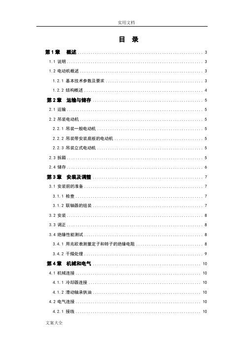
目录第1章概述 (3)1.1说明 (3)1.2电动机概述 (3)1.2.1 基本技术参数及要求 (3)1.2.2 结构概述 (4)第2章运输与储存 (5)2.1运输 (5)2.2吊装电动机 (5)2.2.1 吊装一般电动机 (5)2.2.2 吊装带安装底板的电动机 (5)2.2.3 吊装立式电动机 (5)2.3拆箱 (5)2.4储存 (6)第3章安装及调整 (7)3.1安装前的准备 (7)3.1.1 检查 (7)3.1.2 联轴器的组装 (7)3.2安装 (8)3.3调正 (8)3.4绝缘性能测试 (8)3.4.1 用兆欧表测量定子和转子的绝缘电阻 (8)3.4.2 干燥处理 (9)第4章机械和电气 (10)4.1机械连接 (10)4.1.1 冷却器连接 (10)4.1.2 滑动轴承供油 (10)4.2电气连接 (10)4.2.1 接线 (10)4.2.2 电气及附属设备检查 (10)第5章起动及停车 (12)5.1试起动 (12)5.2转动方向 (12)5.3起动与停车 (12)第6章日常维护 (13)6.1润滑 (13)6.1.1 滚动轴承的润滑 (13)6.1.2 滑动轴承的润滑 (13)6.2振动和噪音 (13)6.3湿度 (13)6.4温度 (13)6.5绝缘电阻的最小值 (14)6.6轴承的更换 (14)6.7定期检查 (15)第7章常见故障及原因分析 (16)第1章概述1.1 说明本说明书为我公司电动机的随机文件。
其中介绍了电动机的结构、储运、安装的要求和注意事项,以及使用、维护电动机的要求、方法和注意事项,使用维护人员必须认真阅读此说明书。
认真审阅电动机上的铭牌、标牌、警示牌等。
使用单位应对操作人员进行专业培训后,方能上岗作业。
只有严格按照本使用说明书、铭牌、标牌、接线牌和警示牌进行安装、使用和维护电动机,我公司才承担相关“三包”责任。
本说明书不可能包括安装、使用和维护方面一切可能发生的问题,如果所发生的问题未包括在本使用说明书和其他随机资料中,用户自己又难以解决,请与本公司联系。
420立式全自动电脑型包装机说明书
汉顿包装机械
P2 P2 P2 P3 P3 P5 P8 P8 P8 P9 P9 P10 P11 P12 P13 P14 P14
第1页
汉顿包装机械
一、 设备说明 1、 概述
CH-420 全自动包装机系我司引进国外先进技术,并加以消化吸收而生产的一种高品
质、高性能的全自动包装机,具有完成自动送料、计量、制袋、充填、封口、打印日期及成
纵封延时 xxx 表示:运膜后至纵封封合前这段时间。
3、需要设定各功能参数时,
用手触摸该功能,则在屏幕左端会显示输入数字的触摸键盘,
这时可进行参数修改,按 ENT 进行确定。按 ES 键取消修改。
修改后必须保存参数。
例如:修改横封得电参数:(将原 0.65 改为 0.75)
触摸横封参数 0.65 则此参数闪烁,同时屏幕显示上图的数字盘,用手触摸 数字盘 0 . 7 5 再按 ENT . 若要取消修改则触摸数字键上的 ES 键。参数
(由于拉膜皮带打滑等原因,可能实际包装出来的长度与设定值有差异,则需加大设定 袋长来修正)。 2、 触摸 下页 屏幕显示:
第7页
汉顿包装机械
充气时间 xxx 表示:充气电磁阀得电时间。
充气延时 xxx 表示:运膜后至充气前这段时间。
运膜延时 xxx 表示:程序接收信号后至运膜前这段时间。
横封延时 xxx 表示:运膜后至横封封合前这段时间。
品输出等一系列自动功能。本机采用高精度伺服运膜系统、PLC 程序控制、先进的触摸式人
机界面、光电自动定位跟踪、数字式温控等,使整机的操作更加简单、完善,是食品包装行
业提高生产效率,降低劳动强度,提高包装档次的首选设备。
2、 性能和规格
电源 包装材料 包装膜厚度 包装膜最大宽度 最大制袋尺寸 包装速度 整机重量
电机使用说明书
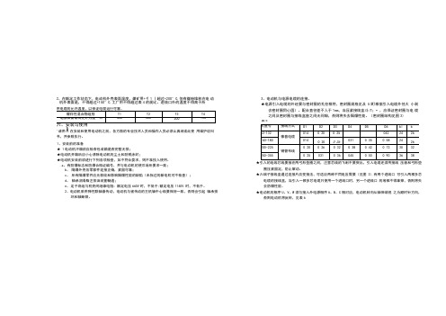
2、在额定工作状态下,电动机外壳表面温度,煤矿用+彳1丨超过+200°C,但有煤粉堆积在电动机外表面是,不得超过+150°C,工厂用不得超过表4的规比。
进线口外的温度不得高于所3、电动机与电源电缆的连接。
★电源引入电缆的外经要与密封圈的孔径相符,密封圈规格见及5(町根据引入电缆外径大小剥去密封圈同心圆)。
配合直径差不人于1mm,当压紧接线盒斗/T;•,应保证密封圈与电缆之间及密封圈与接线盒座之间无间隙,否则将失去隔爆性能。
(密封圈结构见图3)表5'请用A在安装和使用电动机之前,各方面的专业技术人员和操作人员必须认真阅读此使用维护说叫书,并参照执行。
1、安装前的准备★ 1电动机汗箱前应检杳包装箱是否完整无损;★电动机开箱后应小心淸除电动机的尘土和防锈涂封;★电动机安装前须进行下列各项检查,如不符合耍求,则不准投入使用。
.a、有防爆标志和防爆合格证编号,并与电动机的使爪场所要求一致;b、隔爆外壳各零部件连接正确,紧固可靠;c、所有隔爆零件应无裂纹和影响隔爆性能的缺陷(未拆过的新电机可不检查);d、轴承润滑脂注排油装置畅通;e、定子绕组与机壳间绝缘电阻:额定电压660V时,不低于;额定电压1140V 时,不低于。
2、电动机采用弹性联轴器传动,电动机与被传动的主机轴中心线要保持一致,否则会引起轴承损坏和轴断裂。
★引入的电线芯线要接在两弓形垫圈之间,注意芯线的飞刺不要突出,引入电缆还须用接线压板和弓形垫圈压紧固定,防止窜动。
★六端子接线盒通过连接片改变接法,可适应两种不同电压需要(见图3),有两个进线口可引入两根多芯电缆的接线盒,当引入一根多芯电缆只使用一个进线口时,另一个进线口的堵棒不得拿掉,否则将失去防爆性能。
★电动机的相序U、V、W须与接入外电源相序A、B、C相对应,电动机转向从轴伸端视之为顺时针方向,否则电动机将反转,见表6Y接U2产品使用维护说明书表6★电动机接线U,经检汽确认无误后方可接通电源进行空载试运转,并观察电机打尤片常现象,待9转正常后投入负荷运行。
GSB-L1说明书
GSB-L1 型立式高速泵使用说明书
前言
本使用说明书提供了 GSB − L1型立式高速泵的安装、使用、故障处理、 维护保养及备品备件方面的信息。
GSB − L1型立式高速泵为单级单吸部分流式离心泵,由电动机、齿轮增 速箱(二级增速)、泵及其附件组成。性能范围:流量不超过100m3 h ,扬程 不超过1900m ,转速 4,800r / min ~ 23,700r / min ,功率不超过150kW ,吸入压力 不超过 7MPa ,工作压力不超过15MPa ,介质温度 −130o C ~ 340o C 。泵外形如 图一所示。当电机功率大于132kW 或电机重量大于1400kg 时,需要使用电机 支架,其结构关系及安装要求详见主泵随机资料。本说明书侧重于高速泵 本身的安装、使用、保养和检修。
1. 检查 泵到货后,应立即进行外观检查,看有没有在运输过程中造成损坏。
如果有损坏,应立即通知承运人和泵制造厂,但不要自行分解泵。
2. 保管 要是泵不立即安装,则应在原包装箱内放好,出厂时安装的保护堵盖、
堵塞、堵帽等装在原来位置上,然后连同包装箱一起放在清洁、干燥、不 受潮、不沾灰、且距热源和电源大于1m 的地方。电动机的保管参见电动机 安装使用说明书。如保管期超过 6 个月,请与泵制造厂联系。
主油泵为定排量摆线齿轮型油泵,由增速箱输入轴直接驱动。 油冷却器为管壳式水冷型,冷却水压力不大于1MPa ⋅G ,冷却水流量参 见随机资料。通过安装在冷却水排出管线上的手阀调节冷却水流量,保证 增速箱油温在 40o C ~ 70o C 之间。大约在泵起动运行 1 小时后,油温就可稳定。 注意,为防止在润滑油油路上存在气囊,油冷却器的安装位置必须低于油 过滤器。 预润滑系统由外设润滑油泵、单向阀及管线组成。外设润滑油泵有手 动型和电动型两种。其作用是在起动主电机前,给增速箱内的轴承和齿轮 进行预润滑,从而避免在起动时可能引起的轴承及轴组件损坏。起动主电 机前,操纵手动油泵手柄上下运动或起动电动油泵,若油压不低于 0.1MPa ⋅G ,就可起动主电机,主电机起动后,才可停止操纵手动油泵或关 闭电动油泵。 油过滤器为纸质型,过滤精度为 5μm 。每 6 个月应停机更换润滑油和油 过滤器。 根据轴承结构及使用的润滑油情况,正常运转时,增速箱油压应保持 在 0.2 ~ 0.6MPa ⋅ G ,增速箱绝对不能在油压低于 0.14MPa ⋅ G 时工作。用户可根 据需要安装润滑油油压报警开关。
CK5225数控双柱立式车床说明书资料
使用说明书
(机械部分)
中华人民共和国
芜湖恒升重型机床有限公司
敬告用户: 在安装、使用本机床之前,请仔细阅读本使用 说明书,并按本使用说明书的要求进行操作。
公司名称:芜湖恒升重型机床有限公司 公司地址:安徽省芜湖机械工业开发区
目
次
一、概述…………………………………1 二、外型与结构…………………………1 三、主要技术参数………………………2 四、传动系统……………………………5 五、液压系统……………………………5 六、润滑系统……………………………6 七、吊运与安装…………………………7 八、机床的操作…………………………8 九、调整说明……………………………9 十、试车与维护注意事项………………11
CK5225 数控双柱立式车床
使用说明书
表五
CK5225-01001 共 37 页 第 6 页
3、液压装置的型号及名称,见表五: 型号 CB-B16 HY36-25 HY37-25 Y-25B YJ-1 24E-25B 六、润滑系统: 机床的润滑示意,见图七。 1、润滑的部位及方式,见表六 表六
序号 1 2 3 4 5 6 7 8 部件 横梁升降机构 进给箱 蜗轮减速箱 工作台 变速箱 横梁 立刀架 卡盘爪 润滑部位 蜗轮付、轴承 齿轮、轴承 蜗轮付、轴承 导轨.齿轮.轴承 齿轮、轴承 导轨.轴承.齿轮 导轨.轴承.齿轮 卡盘爪、螺杆 润滑方式 油浸 飞溅 油浸 齿轮泵 飞溅 手压油泵 电动润滑泵 润滑油种类
CK5225 数控双柱立式车床
ቤተ መጻሕፍቲ ባይዱ
使用说明书
CK5225-01001
共 37 页
第 8 页
平尺上放一水平仪,记录水平仪的读数,然后将工作台旋转 90°,按同 样的方法检验。水平仪的两次读数值均不得超过 0.04/1000。 ②将立柱用螺钉及锥销与底座固定,并使两立柱的前导轨面必须在同一平 面内,允差为 0.03 毫米,可用塞尺进行检验。如无足够长度的大平尺 时,也可用机床的横梁来代替平尺使用。 ③在左、右立柱上面装上中间梁及顶梁。在中间梁左边与左立柱间装有调 整垫。 ④在左立柱背面装上扶梯。 ⑤卸掉横梁压板螺钉,将压板取下。卸掉夹紧装置的螺母,将夹紧板取 下,再将横梁安装在立柱的导轨上。在横梁左侧面与立柱间插入调整垫 铁,然后装上压板。装上横梁升降丝杠,横梁与工作台面的平行度可用 升降丝杠顶部的螺帽来调整。用方形水平仪放在横梁顶端的导轨面上进 行检查。横梁的安装精度应符合本机床合格证明书的规定。 ⑥安装主电机及电气柜。 ⑦根据电气安装图接通电路,接上接地螺钉。 ⑧机床全部安装完毕后,应重新校正机床水平,并按本机床合格证明书的 要求全面检验和调整机床精度。 八、机床的操作: 1、悬挂按钮站的按钮位置,见图十五。 2、操作部位,见图十六。 3、操作说明:详见使用说明书电气部分 (1)机床开动时,首先按油泵起动按钮,指示灯亮后,方可操作其它动作。 (2)工作台的正反向点动、起动旋转或停止,应分别按相应按钮。 (3)工作台变换转速时,首先拧动开关到所选的位置上,然后按变速按钮, 指示灯亮;当指示灯熄灭时,转速变换完成。转速变换时,必须在工作 台停车时进行。 (4)横梁上升或下降,可分别按相应按钮。横梁升降前应将左、右立刀架移 至横梁升降丝杠位置处,以便保持横梁精度。横梁升降时,必须在工作台 停车时进行。
DM542说明书1

D M542说明书1DM542 4.2A电机驱动说明书DM542是本公司专门针对用户用量较大,同时要求性价比较高的客户应用,对于电机存在有震动,要求噪音又小的用户的首选1供电电压可达48VDC2输出电流峰值可达4.2A3光隔离,输入可以共阴,共阳,差分信号,脉冲最高响应频率200KHz 4低速零震动,且噪音及小5抗干扰能力强,在电网恶劣的环境里,可以实现高精度定位应用领域;自动包装机,点胶机,雕刻机等自动化设备,对于以前用到有震动和噪音较大的用户有明显改善应用范围:所有法兰盘为42,57机身长度在80毫米以下所有电机,以及86短机身电气特性:驱动器功能说明信号接口PUL+和 PUL-为控制脉冲信号正端和负端;DIR+和DIR-为方向信号正端和负端;ENA+和 ENA-为使能信号的正端和负端。
5V-24V通用.无需加电阻电机接口A+和 A-接步进电机A相绕组的正负端;B+和B-接步进电机B相绕组的正负端。
当A、B两相绕组调换时,可使电机方向反向。
电源接口采用直流电源供电,工作电压范围建议为20-50VDC,电源功率大于100W,根据实际使用情况开看,输入在不超过DC40V为合适选择指示灯驱动器有红绿两个指示灯。
其中绿灯为电源指示灯,当驱动器上电后绿灯常亮;红灯为故障指示灯,当出现过压、过流故障时,故障灯常亮。
故障清除后,红灯灭。
当驱动器出现故障时,只有重新上电和重新使能才能清除故障。
安装说明驱动器的外形尺寸为:118××34mm,安装孔距为112mmmm。
既可以卧式和立式安装,建议采用立式安装。
安装时,应使其紧贴在金属机柜上以利于散热。
参数设定DM542驱动器采用八位拨码开关设定细分精度、动态电流和半流/全流。
详细描述如下输出峰值电流SW1SW2SW31.00A on on on1.46A off on on1.91A on off on2.37A off off on2.84A on on off3.31A off on off3.76A on off off4.20A off off offSW4定义:用户可通过SW4来设定驱动器的自动半流功能。
低速电机使用说明书
低速电机使用说明书一、概述1.YDS系列低速电机,采用B级绝缘,防护等级为IP44,适用于驱动无特殊要求的各种机械设备。
2.安装结构形式:立式、卧式、立卧式。
3.低速电机允许在下列条件下使用:1)环境温度:最高为40摄氏度,最低温度为零下10摄氏度。
2)工作环境不应该含有酸性、碱性或其他有腐蚀性的气体。
3)电源频率:50HZ (偏差不超过正负1%)。
4)电源电压;380伏、220伏(单相)(偏差不超过正负5%)5)工作方式:连续工作制(S1).6) 定子绕组温升限值为80 K .二、安装前的检查1.电动机开箱前应检查包装是否完整无损,有无受潮现象。
2.电动机开箱后应小心清除电机上尘土及轴伸防锈层。
3.检查电机的铭牌是否符合要求。
4.仔细检查电动机在运行过程中,有无变形和损坏,紧固件是松动或脱落。
5.用500伏兆欧表测量绝缘电阻,其值不应低于0.5兆。
否则应对定子绕组进行干燥处理。
干燥处理时的温度不允许超过120摄氏度。
三、电动机的安装1、电动机允许用连轴器、正齿轮。
2、采用连轴器传动时,电机轴中心线与负载轴中心线偏差不应超过允许范围,采用正齿轮传动时,其齿轮节圆直径不应小于电机轴直径的三倍。
3、本产品的主要功能是输出旋转扭矩,在使用中不可以使其直接承受太大的轴向力和径向力。
对立式安装的电动机,轴伸除传动轮外不允许再带其他任何轴向负荷装置。
4、输出轴上所安装的零件孔与轴伸装配尺寸应为间隙配合(即按GB1801-79 H7/h6或H8/h6),装配时不得猛烈撞击轴伸。
5、安装平面应当保证机座不产生变形,且牢固可靠。
6、电动机使用环境应保持良好的通风条件。
四、电动机的运转1、电动机可靠接地。
2、三相电动机的接线板上有6个接线柱,分别标有下列标志:U1.V1.W1.U2.V2.W2、接线时应按接线盒内侧的接线图接线。
当电流相序ABCD 分别与接线标志U1.V1.W1相对应时,电动机的转向、从输出端视之为逆时针;更换电源相序,电动机的转向随之改变。
东元电机使用说明书
电动机不立即使用时,请做好存放预防措施,以确保电动机之正常机能。
2.2.1 存放位置:
(a)必须干燥且通风良好,阳光不直接照射及尘埃少,无腐蚀性气体及不虑淹水的地方。 (b)必须无湿气且不过热(近锅炉)、不过冷(近冷冻库)的地方。 (c)放置地面应不受外界影响而振动,且考虑搬运容易之放置。 (d)脚底垫高,防湿气及地面污染。
3.安装…………………………….…………………….…………...…… 6
3.1 安装环境与场所………………………………………….………..…… 6 3.2 基础………………………………………….……….……….………… 6 3.3 联轴器安装……………………………………………….………..…… 8 3.4 皮带传动时之安装……………………………………….……….…… 11 3.5 炼条或齿轮传动……………………..………………….………..…… 13 3.6 电源结线……………………………..………………….………..…… 13
阅读本手册时,请注意下列的安全标志:
警告!
若注意事项被忽略,可能引起人员的电气性伤害。
警告!
若注意事项被忽略,可能引起人员的伤害。
注意!
若注意事项被忽略,可能引起电动机或设备之损害。
2
2. 新品验收、存放、搬运与拆卸
2.1 验收
收到电动机时,请检查下列诸点: ˙请核对电动机铭板内容是否与订购规范相符。 ˙外观涂装颜色及尺寸是否合乎订购规范。 ˙如加装电热器或热保护器、温度检出器时,请核对其铭板是否合乎订购规范。 ˙请检查电动机于运输中有无损伤。 ˙所有附件和说明书等是否齐全适用。 ˙有指定回转方向时,请查看电动机上之方向指示箭头是否正确。 ˙如规范上有特殊要求时,请确认现品是否与规范相符。
电机使用说明书

电机使用说明书简介:本使用说明书旨在向用户提供电机的相关信息和使用指导。
请用户在使用电机前仔细阅读本手册,并按照指示正确操作电机,以确保安全使用并延长电机的使用寿命。
1. 产品概述本电机为直流电机(以下简称“电机”),具有高效、可靠和稳定的特点。
适用于各类机械设备和电子设备的驱动。
本电机具备以下特性:- 高效节能:采用先进的技术,能够最大程度地提高能量转化效率,减少能源浪费。
- 高转速范围:能够满足不同应用领域的需求,提供多种转速选择。
- 静音运行:内部结构设计合理,运行过程中噪音低,不会对环境和使用者造成干扰。
2. 技术参数在选购电机时,务必了解电机的技术参数,以便选择适合自身需求的电机。
2.1 电源要求:- 输入电压:XXV- 频率:XXHz2.2 输出参数:- 转速范围:XXrpm- 功率:XXW- 扭矩:XXNm3. 安装和使用在安装和使用电机之前,请确保已经断开电源,并仔细阅读以下指引。
3.1 安装步骤:a) 确保安装环境干燥、通风良好,并远离易燃或腐蚀性物质。
b) 将电机正确固定在机械设备上,确保电机与设备之间的传动装置连接稳固。
c) 安装完毕后,检查电机是否牢固固定,接线是否正确。
3.2 使用前准备:a) 检查电机工作环境是否符合要求,如温度、湿度等。
b) 检查电源线路是否符合电机的电源要求,确保电源稳定。
c) 检查电机及相关部件是否正常运转,如有异常现象请勿使用,及时联系售后服务。
3.3 使用方法:a) 打开电源,待电机正常运转后,可进行操作。
b) 如需调节转速,请根据需要调整控制器或外部设备的参数,确保电机运行在合适的转速范围内。
c) 在使用过程中,注意观察电机的运行情况,如有异常现象或噪音过大,请立即停机并查找问题原因。
4. 维护与保养为了保证电机的正常运行和延长使用寿命,请遵循以下维护与保养指南:4.1 定期清洁:定期清洁电机外观,防止灰尘和杂物对电机造成损害,并确保通风孔畅通。
Z5140型立式钻床说明书

Z5150型立式钻床说明书目录一、机床外观图 (2)二、机床安全注意事项 (2)三、机床主要用途和功能特性 (4)四、机床主要规格与参数 (5)五、机床正确使用的具体说明和步骤 (6)1、吊运与安装 (6)2、机床的操纵 (8)3、机床的传动系统 (11)4、机床的调整 (16)5、机床的润滑 (17)6、机床的滚动轴承 (19)7、电气系统 (21)六、机床的维护保养、故障类型及排除 (28)1、维护保养 (28)2、故障的排除 (28)七、易损件明细表及易损件零件图 (29)1、易损件明细表 (29)2、易损件零件图 (29)一、机床外观图图1-1 机床外观图二、机床安全注意事项1、机床在搬运时,依次按包装箱上指定的位置系索,不准倒置、侧置及过大倾斜,不准过大的冲撞和震动,机床吊运时,用钢丝绳和铁棒,吊运机床用的铁棒直径不小于φ30mm,伸出机床两侧的长度不小于300mm。
2、主轴箱升降必须松开镶条的紧固螺栓16(图5-3 操纵手柄),主轴箱升降完毕必须锁紧螺栓,不允许不松螺栓硬摇主轴箱,以免损坏相关的零件。
3、机床主轴没有完全停止转动前,不允许用手去触摸主轴,以免伤人。
4、开车时不得变换转速及进给量,变速必须停车,禁止反接制动,否则将造成齿轮损坏。
5、清洗机床和维修机床打开电柜时,必须关闭机床总电源,否则后果自负。
6、机床切削时,应采取相应的措施,防止铁屑飞溅伤人。
7、不允许在超出机床最大切削参数时进行切削。
8、用退刀楔退刀时,主轴必须退回到原始位置。
9、机床启动前,应检查各手柄的位置是否正确。
10、机床在第一次使用或长时间没有使用时,应先让机床由低、中、高各转速级运转几分钟。
11、机床停止工作时,应切断机床供电电源。
12、推荐切削参数表2-1 机床按下表选用参数在实体上钻最大孔径注:⑴、为确保机床正常运转,必须在刀具锋利的条件下工作,如果刀具钝可能超出机床切削范围,有可能损坏机床。
⑵、在实体上钻最大孔时,切削参数不得超出表中推荐的数值,否则有可能损坏机床。
电机使用说明书-上海上电电机股份有限公司

电机使用说明书Operating Manual概述本说明书适用于我公司生产的YX3、YET、Y2、YVP、YD系列低压三相异步电动机及其派生系列产品OverviewThe manual serves YX3、YET、Y2、YVP、YD Series low voltage asynchronous motors and it's derivative products as well.开始使用Putting into use (starting)收货检查Reception check收到电机后立即检查是否有损坏,如发现请立即拨打电话:0086-21-6463-1777,或发传真至0086-21-6463-7180,检查铭牌数据特别是额定电压、接线方式(星形或三角形)是否与合同订货要求相符,用手转动电机轴检查轴转动是否灵活。
Immediately check the motor for external damage upon receipt and if found, please inform us by telephone or fax without delay (Tel:0086-21-6463-1777, Fax:0086-21-6463-7180). Check all rating plate data, especially voltage and winding connection (star or delta). Turn shaft by hand to check for free rotation.绝缘电阻检查Insulation resistance check在电机调试前或怀疑线圈受潮时要测量电机的绝缘电阻,在25℃时的绝缘电阻值应超过以下表达式的值,表达式中:Measure the motor's insulation resistance before commissioning or when winding dampness is suspected. insulation Resistance, measured at 25°C, shall exceed the following reference value, i.e. where:R:单位兆欧(用500V绝缘电阻表测量)Array U表示电压,单位VP表示功率,单位kWR: MΩ( measured with 500 V dc Megger )U = voltage, Volts;P = output power, kW.警告:测量完绝缘电阻后应立即将测量线从电机上断开,以免线圈再次受到高电压冲击。
立式平衡机说明书
谢谢您的支持与合作
-1-
深圳市新力平衡机
安全方面的注意事项
(用前必读) 在进行设备的安装﹑运行﹑保养﹑检修之前,请务必熟读此使用说明书。请 在熟悉机器的有关知识,安全信息和注意事项之后使用。 在该使用说明书中,安全注意事项的严重程度分为 “危险”和“注意”两类. 设想当错误时,会发生危险,有可能导致人员伤 亡或受重伤。 设想当错误安装时,会发生危险,有可能导致人 员受中等伤害或轻伤,以及造成物质损失。
九.定标操作流程图 开机自检显示 SLC 2008 安装好校验的工件后按“SET”后输入“00” 显示:CAL=A00 按“EXE”键 显示输入转速 SP=XXXX 按“EXE”键 显示输入小数点 PP=2 或 3 按“EXE”键 显示提示启动 RUN 启动电机 进入测量状态, 数秒后,声光报警 提示停车 停止电机 显示 CAL=A12 按“EXE”键 显示提示输入定标 试重重量 AP=XXXX 1.在工件校正半径、 0 度方向加上定标试重 2.按“EXE”键 显示提示启动 RUN 启动电机 进入测量状态, 数秒后,声光报警 返回显示 SLC2008 “定标操作”完成,可执行“测量操作”和 “夹具偏心补偿操作” 。
-3-
深圳市新力平衡机 一、概述
1、本电测箱适用于单面软硬支承平衡机不平衡振动信号的检测。 电测箱输入量: a.传感器输入转子支承的不平衡振动信号。 B.一个由接近开关输出的基准信号。 电测箱输出量:全部由数字显示转子校正平面、校正半径上 的不平衡量大小、相位及平衡转速。 电测箱采用工业计算机 (单片机) 和国际通用数字和模拟集成电路, 操作方便 、显示直观、性能稳定、工作效率高等。 2. 电测箱工作环境: ( 1)环境湿度 ( 2)空气相对湿度 ( 3)电源电压 ( 4)电源频率 °C 40° 0°C <t< 40 ≤85%(25 °C) ±10% AC220 AC220± ±5% 50Hz 50Hz±
电动机使用说明书
电动机使用说明书目录第1章概述 (4)1.1说明 (4)1.2电动机概述 (5)基本技术参数及要求 (5)结构概述 (7)第2章运输与储存 (8)2.1运输 (8)2.2吊装电动机 (8)吊装一般电动机 (9)吊装带安装底板的电动机 (9)吊装立式电动机 (9)2.3拆箱 (10)2.4储存 (10)第3章安装及调整 (11)3.1安装前的准备 (11)检查 (11)联轴器的组装 (13)3.2安装 (13)3.3调正 (14)3.4绝缘性能测试 (15)用兆欧表测量定子和转子的绝缘电阻 15干燥处理 (15)第4章机械和电气 (17)4.1机械连接 (17)冷却器连接 (17)滑动轴承供油 (17)4.2电气连接 (17)接线 (17)电气及附属设备检查 (18)第5章起动及停车 (20)5.1试起动 (20)5.2转动方向 (20)5.3起动与停车 (21)第6章日常维护 (23)6.1润滑 (23)滚动轴承的润滑 (23)滑动轴承的润滑 (23)6.2振动和噪音 (24)6.3湿度 (24)6.4温度 (25)6.5绝缘电阻的最小值 (26)6.6轴承的更换 (27)6.7定期检查 (28)第7章常见故障及原因分析 (31)1.1 说明本说明书为我公司电动机的随机文件。
其中介绍了电动机的结构、储运、安装的要求和注意事项,以及使用、维护电动机的要求、方法和注意事项,使用维护人员必须认真阅读此说明书。
认真审阅电动机上的铭牌、标牌、警示牌等。
使用单位应对操作人员进行专业培训后,方能上岗作业。
只有严格按照本使用说明书、铭牌、标牌、接线牌和警示牌进行安装、使用和维护电动机,我公司才承担相关“三包”责任。
本说明书不可能包括安装、使用和维护方面一切可能发生的问题,如果所发生的问题未包括在本使用说明书和其他随机资料中,用户自己又难以解决,请与本公司联系。
注意:为保证设备安全和正确的安装、操作和维护,请务必遵守本说明书的相关条款。
电机使用说明书

电机使用说明书Operating Manual概述本说明书适用于我公司生产的YX3、YET、Y2、YVP、YD系列低压三相异步电动机及其派生系列产品OverviewThe manual serves YX3、YET、Y2、YVP、YD Series low voltage asynchronous motors and it's derivative products as well.开始使用Putting into use (starting)收货检查Reception check收到电机后立即检查是否有损坏,如发现请立即拨打电话:0086-21-6463-1777,或发传真至0086-21-6463-7180,检查铭牌数据特别是额定电压、接线方式(星形或三角形)是否与合同订货要求相符,用手转动电机轴检查轴转动是否灵活。
Immediately check the motor for external damage upon receipt and if found, please inform us by telephone or fax without delay (Tel:0086-21-6463-1777, Fax:0086-21-6463-7180). Check all rating plate data, especially voltage and winding connection (star or delta). Turn shaft by hand to check for free rotation.绝缘电阻检查Insulation resistance check在电机调试前或怀疑线圈受潮时要测量电机的绝缘电阻,在25℃时的绝缘电阻值应超过以下表达式的值,表达式中:Measure the motor's insulation resistance before commissioning or when winding dampness is suspected. insulation Resistance, measured at 25°C, shall exceed the following reference value, i.e. where:R:单位兆欧(用500V绝缘电阻表测量)Array U表示电压,单位VP表示功率,单位kWR: MΩ( measured with 500 V dc Megger )U = voltage, Volts;P = output power, kW.警告:测量完绝缘电阻后应立即将测量线从电机上断开,以免线圈再次受到高电压冲击。
C5116E使用说明书

第5页
共10页
3.辅助操作面板操作
1)电源:转动钥匙开关,SINUMERIK802D系统上电,系统开始工作。
2)横梁上升:按下此键,如果处于JOG方式,而且梁可以移动则按钮指示灯亮,横梁锁紧阀松开,松开到位时横梁上升,遇到上限位开关横梁停止上升。
3)横梁下降:按下此键,如果处于JOG方式,而且梁可以移动则按钮指示灯亮,横梁锁紧阀松开,松开到位时横梁下降,遇到下限位开关横梁停止下降
(1)Y起动
按压起动按钮PB1,经PLC按已存程序判断使接触器KM53线圈得电,触点动作完成对电动机绕组相Y接,同时KM51(反转时KM52)接触器线圈得电,触点动作,接通电动机M5供电电源,电动机M5“Y”接转动。
工大数控
使用说明书
C5116E数控立式车床
第8页
共10页
(2)Y-△变换
当电动机Y接运转10秒时,经PLC内部按程序判断,使KM53接触器线圈断电,其触点解除电动机M5绕组Y接状态,KM53断电后,又经0.5秒延时,KM54接触器线圈得电,其触点完成对电动机M5绕组的△接,实现了Y-△变换。
1)保持按钮、开关均在所需位置上;
2)接通电源;
3)点动各运转部份,检查各传动系统是否正常;
4)在JOG方式下按REF键进行X、Z轴的回零操作;
5)安装加工零件,利用X、Z轴点动按钮对刀(定起点始),确定操作正确后,才可进入自动程序操作。
2.断开电源
1)机床运动部件均已停止;
2)或按数控停止按钮;
3)断电源总空气开关。
3)返回参考点
在JOG下,按REF进入回参考点方式,各坐标返回参考点后,建立机床测量起始点。操作步骤:
进入REF方式;
电动机说明书(上海电机)

4. 检查及维护4.1 引言——为了保证连续安全可靠使用,必须制定维护大纲。
4.2 电动机在运行时的常规检查上海电机厂建议要经常检查润滑油系统。
应检查所有油位表中的油位。
通过油环视察窗查看油环的旋转情况。
如果发现漏油,应追查根源并加以纠正。
监视润滑油的变色及污染情况。
注意任何噪声或振动的突然增大或过大,并应迅速纠正。
在连续运行期间定期检查轴承温度,检查定、转子之间的间隙,清理集电环和刷架上的积灰和油污,至少每星期一次。
4.3维护计划4.3.1 对于一般的使用条件,推荐以下维修计划。
4.3.1.1 在提供的测温装置处测量温度,它们时为了测量定子绕组、冷却空气及轴承的温度。
(例如埋入式电阻测温元件)。
4.3.1.2 查听整个电动机是否有不正常的机械噪声或者出现变化的响声(例如摩擦或敲击声等)。
4.3.1.3 当具有水——空气交换器装置时,用目检查水管是否漏水。
4.3.1.4 当采用过滤器装置时,检查过滤器的沾污程度。
4.3.1.5 用手检查或用温度计(如果装有)在测温装置处测量并记录轴承温度。
检查定、转子之间的间隙,清理集电环和刷架上的积灰和油污。
4.3.2 每月的检查。
4.3.2.1 用轻便型测量设备测量振动。
测量点位置在轴承室中部。
4.3.2.2 检查所有电缆,联接线及其紧固情况。
4.3.2.3 如果是线绕式转子,检查在滑环、导电螺杆及电刷装置上灰尘沉积的程度。
需要时清除沉积的灰尘。
检查电刷的摩损及在刷握中自由活动的情况。
如果需要,则更换电刷。
4.3.2.4 当具有过滤器装置时,在过滤监视器动作后(例如压差开关)则应更换或清理过滤器。
4.3.2.5 在油润滑的轴承中,检查油环运转是否平稳以及带油情况。
检查轴承密封是否漏油,如果已弄脏,则清除脏物。
检查供油设备。
4.3.3 每季的检查。
4.3.3.1 测量定、转子绕组的绝缘电阻。
4.3.3.2 用一只额定电压为500至625伏的兆欧计测量绝缘的轴承或座与钢的基础之间的绝缘电阻。
DVT630X40-100Q数控立式车床说明书
34
NU207E
圆柱滚子轴承
35×72×17
2
35
31308
圆锥滚子轴承
40×90×25.25
2
36
31208
圆锥滚子轴承
40×80×19.75
2
37
NU207E
圆锥滚子轴承
35×72×17
2
38
NKI55/35
滚针轴承
55×72×35
4
39
81215
推力滚子轴承
55×90×25
4
DVT630×40/100Q-NC
推力球轴承
60×110×35
4
25
22215
调心滚子轴承
75×130×31
2
26
7312B
角接触球轴承
60×130×31
2
27
7315B
角接触球轴承
75×160×37
4
DVT630×35/100Q-NC
〈200410038〉
使 用 说 明 书
共 47 页
第 16 页
续上表
部别
序号
型 号
名 称
规 格
公差等级
1.2.19 机床总功率 190KW
1.2.20 机床重量(约) 215t
DVT630×40/100Q-NC
〈200410038〉
使 用 说 明 书
共 47 页
第 4 页
2、主要用途和特性
该机床是一种万能型数控双柱立式车床,适于零件种类变化大的单件,小批量的零件加工。
该机床适用于高速钢和硬质合金刀具,对黑色金属,有色金属和部分非金属零件的粗、精加工,可进行内圆柱面,内、外圆锥面、圆弧面及槽的加工。
立式电机安装方法
立式电机安装方法全文共四篇示例,供读者参考第一篇示例:立式电机是工业生产中常见的一种驱动设备,它具有占地面积小、安装方便、使用灵活等特点,被广泛应用于机械、化工、电力等领域。
为了确保立式电机的安全稳定运行,正确的安装方法尤为重要。
本文将介绍关于立式电机安装的方法,希望对读者有所帮助。
一、准备工作在进行立式电机安装之前,需要做好充分的准备工作。
首先要检查电机和其配件是否完好,是否符合安装要求。
其次要了解电机的安装环境和要求,包括安装位置、基础条件、环境温度等信息。
最后要准备好必要的安装工具和设备,确保安装顺利进行。
二、安装位置选择选择合适的位置是立式电机安装的第一步。
一般情况下,立式电机应安装在平整、通风、无尘、湿度适中的环境中。
同时要考虑设备的排气、散热和维修保养的便利性。
确保立式电机的运行不会受到外界环境的影响,保证安全稳定的运行。
三、基础与支座安装在选择好安装位置后,需要进行基础与支座的安装。
首先要清理安装位置,确保基础平整、稳固。
然后根据电机的尺寸和重量选择合适的支座进行安装,确保支座与基础之间的平衡稳定。
同时根据电机的要求和基础条件进行固定,巩固支座与基础的连接。
四、电机安装将电机放置在安装位置上,根据电机的安装要求进行连线和接线。
首先要根据电机端子识别电源的导线位置,确定接线方式。
然后根据电路图将电源线、接地线和控制线连接到合适的端子上。
接线完成后,要进行电机转向的检测和调整,确保电机运行正常。
五、调试与测试完成电机安装后,需要对电机进行调试和测试。
首先要检查电机的连接是否牢固,电路是否接通,电源是否正常。
然后可以按照电机的启动程序进行调试,检查电机的运转情况和声音是否正常。
最后要根据电机的技术要求进行静态与动态的测试,确保电机可以安全、稳定地运行。
六、保养与维护完成电机安装后,要做好电机的保养与维护工作。
根据电机的使用情况和要求,定期对电机进行检查、清洁和维护,维护电机的正常运转。
在发现异常情况时要及时处理,确保立式电机的长期稳定运行。
- 1、下载文档前请自行甄别文档内容的完整性,平台不提供额外的编辑、内容补充、找答案等附加服务。
- 2、"仅部分预览"的文档,不可在线预览部分如存在完整性等问题,可反馈申请退款(可完整预览的文档不适用该条件!)。
- 3、如文档侵犯您的权益,请联系客服反馈,我们会尽快为您处理(人工客服工作时间:9:00-18:30)。
YZDL series vertical vibrating motor:
Introduction:
YZDL vertical vibration motor is the power source and vibration source of vibration source, a set of adjustable eccentric block is installed on the rotor shaft on both on both ends of the vibration motor. To produce the centrifugal force generated by high speed rotation shaft and eccentric block vibration force. High utilization rate of the exciting force of vibration motor, low energy consumption, low noise and long service life. The vibration force of vibration motor vibration force can be adjusted, easy to use, and can be applied to general mechanical vibration field.
Product principle:
The running of motor will produce in the direction of horizontal, vertical, inclined and etc vibration force. Making the material fast plane scattered, center gathered, three-d rotation movement of a variety of ways. With its unique structure adapted to the different machines to the requirement of vibration source.
Applied field:
The motor is widely used in vibration crusher, vibrating screen, packing machine, vibration shakeout machine, vibration molding machine, vibration pile driver, hoist, vibration filling machine, the vibration of the bunker broken arch block and so on. So it is widely used in hydropower construction, thermal power, construction, building materials, chemical, mining, coal, metallurgy, light industry and other industries. Features:
1)Scientific design, simple structure, low noise and long service life.
2)Seal design, can work in any environment with no explosion-proof requirements.
3)Exciting force is easy to adjust.
4)It can be used in standalone unit, the synthesis of various vibration form, can reached the required job requirement.
5) It is applicable to the vibrating feeder, vibrating conveyor, vibrating screen extension vibration machinery and equipment, etc
Structure diagram
Technical parameter:
Size Model L1 L2 B φ1φ2φ3n d L3 R
power
(kw)
YZDL-3-4 250 170 16 190 125 150 4 11.5 70 0.12
YZDL-5-4 285 186 20 230 155 200 4 M10 85 0.37
YZDL-8-4 324 210 23 245 165 210 6 11.5 120 135 0.55
YZDL-15-4 343 223 24 270 190 235 6 14 128 140 0.73
5 YZDL-30-4 464 294 32 310 220 265 8 18 188 185 1.5
YZDL-40-4 464 294 34 310 220 265 8 18 188 185 1.84
YZDL-50-4 562 353 40 400 320 360 8 20 208 200 2.2 YZDL-60-4 590 370 46 460 340 390 8 22 238 250 3.0 YZDL-80-4 680 430 56 520 380 480 8 30 260 310 5.5。
