sweethome3D v3-7用户手册
Sweet Home 3D配合SView软件,生成实际的彩色立面图的方法
Sweet Home 3D配合SView软件,生成实际的彩色立面图的方法
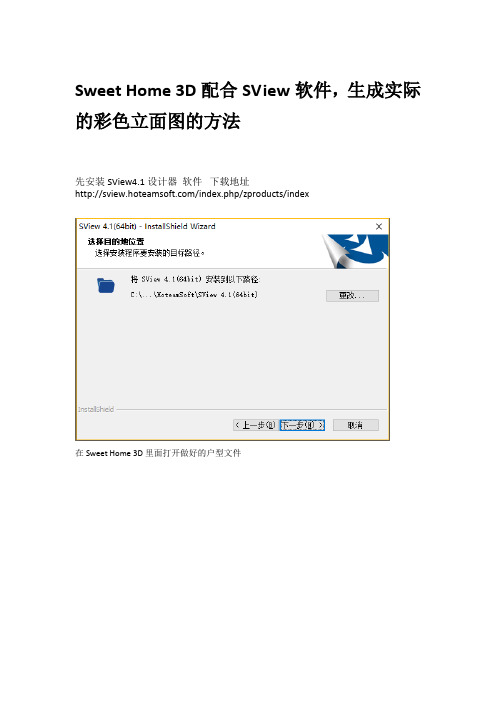
先安装SView4.1设计器软件下载地址
/index.php/zproducts/index
在Sweet Home 3D里面打开做好的户型文件
在Sweet Home 3D平面图删掉多余的墙体和家具,只留想在这次立面图中保留的东西删完了,3D图是这个样子的
视角放横,看看有没什么遗漏的
确定后,不选择任何物件,在3D视图菜单里选择导出为OBJ格式,来导出文件
点击SVIEW图标,进入SVIEW软件,选择免费的基础功能版在软件的文件菜单中打开刚才导出的OBJ文件
默认菜单按钮
要改成这样,半透明的样式,再按鼠标滚轮放大,就可以了,截图并保存这个图,后面要用SVIEW还有线条样式(可不做)
SVIEW默认的原始着色样式(可不做)
SVIEW你可以将局部放大看细节,用鼠标滚轮(可不做)
好了,把上保存的截图,导入到Sweet Home 3D新文件中,用鼠标右键菜单的导入背景图像命令
选择刚才的图片,拉动蓝色的比例线条的左右两个端点到图上房屋的左右两端。
在上面的线段实际长度处,输入我们的实际长度830厘米(去我们的户型文件中用绘制标注测量出来的房屋最左边到最右边的长度)
点继续,坐标原点随便点(蓝色点),建议房屋左上角,或者左下地平线位置。
点击完成
导入完成后,这样的。
点击放大镜,放大
就可以用Sweet Home 3D的绘制标注功能,愉快的标注了,如果你比例尺是设置正确的话,标注的尺寸就是完全正确的。
完成后截图,直接用或者在Sweet Home 3D打印出平面图。
或者菜单里导出SVG出去用PS2017再编辑加工都可以。
天工空三软件用户手册

5.5.2.9 全图显示(所有影像)............................................................ 24
5.5.2.10 多影像按比例显示................................................................. 24
5.2Pos 引导匹配 ............................................................................................... 20
5.3 精确匹配 .................................................................................................... 20
ห้องสมุดไป่ตู้
3.2 常规流程 .................................................................................................... 13
第四章
数据准备及工程创建 ................................................................................. 14
2.3 软件卸除 .................................................................................................... 10
2.4 加密狗安装................................................................................................. 12
仙妮蕾德v3说明书

仙妮蕾德v3说明书安装:GTA San Andreas User Files 、 gta_sa.exe 和说明没用扔掉它,GTA3所TXD和DFF文件导入GTA3怎么操纵自己慢慢琢磨、此版本最大的亮点是加入变身系统,也就是必须变成钢铁侠才能拥有技能。
普通的cj没有钢铁侠的技能,而且从高处掉下来会摔倒….变身介绍:小数点+1 MK42小数点+2 MK4小数点+3 战争机器小数点+4 MK2小数点+5 MK6小数点+6 MK17小数点+7 MK38小数点+8 MK25小数点+9 MK40小数点+* 变成CJ/加1 MK5/加2 MK3/加3 爱国者/加4 MK35/加5 MK37/加6 MK22/加7 MK39/加8 MK7/加9 MK3018套铠甲任你选。
每一个盔甲都有不同的能力,自己去体验吧。
注意:此版本已优化,切换技能时直接选择需要的技能。
Y是关闭键介绍主要功能手炮(单手):大键盘1开启,鼠标右键+w瞄准鼠标左键发射(MK42,MK4,MK6,MK17,MK40)手炮(双手):大键盘2开启,同上。
胸击炮(已优化):大键盘3开启(MK42,MK4,MK17)单手机枪:大键盘4开启导弹:输入MI开启,鼠标右键加w瞄准,鼠标中键发射(MK42,MK4,MK6)飞行按(;)奔跑按键加速,跳跃按键减速,空中F熄火自由落体落地冲击当钢铁侠落到地面时,会产生强大的冲击力,地面裂开,附近的人死亡,车子爆炸。
变成CJ会摔倒另外战争机器专用技能:1肩上加特林必须变成战争机器才可以使用。
大键盘5开启。
(操作同上)2双手机枪+肩上加特林大键盘6开启(操作同上)。
homer3使用手册

homer3使用手册Homer3 使用手册目录1. 引言2. 安装与配置2.1 系统需求2.2 安装2.3 配置3. 功能概述3.1 模块介绍3.2 功能特点4. 开始使用4.1 创建项目4.2 导入素材4.3 基本编辑功能4.4 添加特效与过渡4.5 音频处理4.6 视频导出5. 高级功能5.1 高级编码选项5.2 多轨道编辑5.3 高级特效与过渡5.4 图片与文字编辑6. 故障排除与技巧6.1 常见问题解答6.2 快捷键与技巧7. Homer3 社区与资源7.1 官方论坛7.2 帮助文档与教程7.3 优秀作品展示8. 结束语1. 引言Homer3 是一款功能强大的视频编辑软件,可以帮助用户轻松创建精美的视频作品。
本手册将为您介绍如何安装、配置和使用Homer3 的各项功能。
2. 安装与配置2.1 系统需求在安装之前,请确保您的计算机满足以下系统需求:- 操作系统:Windows 7/8/10,Mac OS X 10.10 或更新版本- 处理器:双核 2.0GHz 或更高- 内存:4GB 或更高- 存储空间:至少 1GB 可用空间- 显卡:支持 OpenGL 3.3 或更高版本2.2 安装以下是在不同操作系统上安装 Homer3 的步骤:Windows 用户:1. 下载安装程序(.exe 文件)。
2. 运行安装程序,并按照提示进行安装。
3. 安装完成后,您可以在开始菜单中找到 Homer3 图标。
Mac 用户:1. 下载安装程序(.dmg 文件)。
2. 双击打开安装程序,并将 Homer3 图标拖到应用程序文件夹中。
3. 在应用程序文件夹中找到 Homer3 图标,并双击运行。
2.3 配置在第一次运行 Homer3 之前,您需要进行一些简单的配置:1. 打开 Homer3 软件。
2. 在设置界面中,您可以选择默认的保存路径、语言等选项。
3. 根据个人需求进行配置,并保存设置。
3. 功能概述3.1 模块介绍Homer3 主要由以下几个模块组成:- 导入与编辑:用于导入视频、音频、图片等素材,并进行基本的编辑操作。
智能家居Android手机客户端使用说明书20111111(V1.1)

家居智能控制系统SmartHome 手机版使用说明书使用本产品前请仔细阅读本使用说明书V1.0声明 (3)第一章 功能特点 (4)1.1家居控制 (4)1.2场景控制 (4)1.3安防控制 (4)1.4家居视频 (4)第二章 使用说明 (5)2.1网络连接 (5)2.2登录 (5)2.3设置 (5)2.3.1设置服务器地址 (6)2.3.2安防密码设置 (6)2.3.3用户密码设置 (7)2.3.4切换智慧管家设备 (7)2.4主界面 (8)2.5家居控制 (8)2.5.1设备筛选 (9)2.5.2灯光控制 (11)2.5.2.1不可调光控制 (11)2.5.2.2可调光控制 (12)2.5.3窗帘控制 (13)2.5.4插座控制 (13)2.5.5投影仪控制 (13)2.5.6电视控制 (14)2.5.7音响控制 (14)2.5.8空调控制 (15)2.5.9IPTV控制 (16)2.5.10背景音乐控制 (16)2.5.11DVD控制 (16)2.6.场景控制 (17)2.7.安防控制 (18)2.7.1防区设置 (18)2.7.2安防组合 (19)2.7.3告警历史 (19)2.8.家居视频 (22)声明欢迎使用家居智能控制系统SmartHome使用说明书。
在第一次安装和使用本产品之前,请您务必仔细阅读随机配送的所有资料,这会有助于您更好地使用本产品。
如果您未按本使用说明书的说明及要求操作本产品,或因错误理解等原因误操作本产品,本公司将不对由此而导致的任何损失承担责任。
本公司已经对本使用说明书进行了严格仔细的校勘和核对,但我们不能保证本使用说明书完全没有任何错误和疏漏。
本使用说明书中的图片仅供参考,如果有个别图片与产品的实际显示不符,请以产品实际显示为准。
为更好地提供服务,本公司保留对本使用说明书中描述的产品和软件程序以及本使用说明书的内容随时进行改进和/或修改的权利,恕不另行通知。
本公司对于因软件、硬件的误操作、产品维修或者其他情况引起的数据资料丢失和损失不负任何责任,也不对由此造成的其他间接损失负责,请随时备份您的数据资料。
三维监控控制键盘使用说明书

三维监控控制键盘使用说明书三维监控控制键盘(KEYBOARD CONTROLLER)使用说明书Operation InstructionCopyright 2003-2007. All Rights Reserved.精心整理,用心做精品0温馨提示:感谢您使用本公司产品。
为了让您能够尽快熟练的操作本机,请您仔细阅读我们为您配备内容详细的使用说明书,从中您可以获取有关产品安全注意事项、产品介绍以及产品使用方法等方面的知识。
当您阅读完说明书后,请将它妥善保存好,以备日后参考。
如果您在产品的使用过程中发现什么问题,请拨打我们的服务热线。
谢谢您的合作!申明:在编写此说明书时我们非常小心谨慎,并认为此说明书中所提供的信息是正确可靠的,然而难免会有错误和疏漏之处,请您多加包涵并热切欢迎您的指正。
但是我们将不对本手册可能出现的问题和疏漏负责。
同时,由于我们无法控制用户对本手册可能造成的误解,因此,将不负责在使用本手册的过程中出现的事故或由此引起的损坏。
对于因使用本产品所造成的任何损坏第三方的索赔不负责任。
对于因软件的误操作、产品维修、或其它意外情况等引起资料的删改或丢失不负任何责任,也不对由此造成的其它间接损失负责。
本产品的发行和销售由原始购买者在许可协议条款下使用。
未经允许,任何单位和个人不得将本说明书全部或部分复制、再生或翻译成其它机器可读形式的电子媒介。
本说明书若有任何修改恕不另行通知。
因软件版本升级而造成的与本说明书不符,以软件为准。
注:本设备在出厂前已经过严格的质量测试,符合国家电磁辐射标准,对人体无电磁辐射伤害。
精心整理,用心做精品1目录设备概述 (4)第一部分控制摄像机 (6)1.1选择摄像机 (6)1.2控制摄像机方向 (6)1.3控制摄像机镜头 (6)1.4预置位操作 (7)1.4.1设置预置位 (7)1.4.2调用预置位 (7)1.4.3清除预置位 (7)1.5图像返回 (7)1.6自动巡视 (7)1.6.1设置巡视队列 (7)1.6.2调用巡视队列 (8)1.7轨迹扫描 (8)1.7.1设置轨迹扫描 (8)1.7.2调用轨迹扫描 (8)1.8区域扫描 (8)1.8.1设置区域扫描 (8)1.8.2调用区域扫描 (8)1.9云台自动扫描 (9)1.10操作辅助功能 (9)1.11智能摄像机菜单设置 (9)第二部分控制数字录像机 (9)2.1选择数字录像机 (9)2.2图像监控 (10)2.3多画面监控 (10)2.4图像浏览 (10)2.5图像播放、暂停 (10)2.6图像快退、快进 (10)2.7图像段首、段末 (10)精心整理,用心做精品22.8图像录制 (10)2.9图像停止 (10)2.10信息显示 (11)2.11录像机菜单设置 (11)2.12退出控制数字录像机 (11)第三部分监控键盘设置 (11)3.1通讯速率设置 (11)3.2控制协议设置 (12)3.2.1智能摄像机协议设置 (12)3.2.2数字录像机协议设置 (13)3.3操作员设置 (13)3.3.1设置键盘号 (13)3.3.2设置操作员密码 (13)3.4常规设置 (14)3.4.1按键声音 (14)3.4.2背光控制 (14)3.4.3恢复出厂设置 (14)3.5语言选择 (15)3.6软件版本 (15)3.7退出 (15)第四部分键盘连接 (16)4.1 键盘与智能摄像机、解码器连接示意图 (16)4.2键盘与数字录像机连接示意图 (17)安全事项 (18)精心整理,用心做精品3键盘控制器KEYBOARD CONTROLLER设备概述:监控控制键盘是以操作控制智能摄像机、数字录像机为特色的操作设备。
Sweet_Home_3D使用图解教程
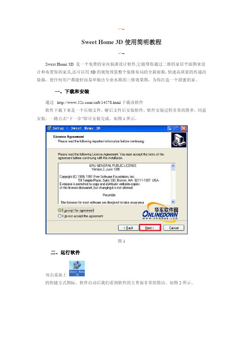
Sweet Home 3D使用简明教程Sweet Home 3D 是一个免费的室内装潢设计软件,它能帮你通过二维的家居平面图来设计和布置你的家具,还可以用3D的视角预览整个装修布局的全新面貌,快速高质量的传递渲染器,使任何用户都能轻而易举做出专业水准的三维效果图,为你打造一个甜蜜的家。
一、下载和安装通过/soft/14578.html下载该软件软件下载下来是一个压缩文件,解后文件后安装软件,软件安装过程非常的简单,同意安装,一路点击“下一步”即可安装完成。
如图1所示。
图1二、运行软件双击桌面上的快捷方式图标,软件启动后我们看到软件的主界面非常的简洁。
如图2所示。
图2软件的主界面分为四个窗口组成。
如图3所示。
图3家具显示窗口:这个目录是有组织的分类,并包含了所有家具和物品,你可以放入你的主设计,选中家具显示:此窗口显示你家中所有家具的名称、大小等方面的特点。
二维窗口:此窗口显示你设计效果图的二维平面效果图。
三维窗口:显示你设计的三维效果,各个角度显示,便于观察效果。
三、设计效果图1)创建墙壁首先保存文件工程,防止丢失文件。
然后点击“Plan/Create walls”工具或直接点击主办面上方的创建墙壁快捷图标,把鼠标移动到二维窗口,单击鼠标左键创建墙壁,绘制墙壁的同时我们看到三维显示窗口也显示绘制立体效果,不。
如图4所示。
图4绘制到最后终点时双击,封闭墙壁。
如图5所示。
图52)调整墙壁因为在绘制过程中有些地方不是很精确,所以要利用工具来调整。
选择“Plan/Select”或直接点击界面上方的“”选择工具快捷图标,选中墙壁把鼠标移动动关键点上此时鼠标将变成十字状态,然后开始调整墙壁的位置、长短。
如图6所示。
图6在调整的时候一定要注意每个墙角一定要封闭。
房间的形状根据自己的喜欢而定。
如图7所示。
图7外墙调整好以后,再来分割一下房间,房间的分割随用户自己定。
在这里分布的情况如下图。
如图8所示。
图83)添加门窗在家具显示窗口中点击“Doors and windows”在此选择喜欢的门窗,选中以后,拖到二维显示窗口,同时三维窗口也显示出来了。
V7 V3 用户手册说明书

V7 V3User Manual - EN Thank youWe would like to thank you cordially for choosing this sE microphone! This manual contains some important instructions for setting up and operating your new equipment. Please take a few minutes to read the instructions below carefully. We hope you will enjoy working with it as much as we enjoyed designing and building it for you.Most Sincerely,Your sE TeamBrief DescriptionThe V7 and V3 are dynamic hand-held microphones ideal for vocal applications on the stage. Thanks to their well-balanced, neutral sound, they also allow the capture of nearly any source from electric guitar cabinets to brass instruments, drums to choir, and more - both in the studio and on the stage. The robust all-metal construction, stainless spring steel mesh grille and gold-plated XLR contacts ensure durability and reliability with no corrosion for many years. Proven Neodymium magnets, tight production tolerances and high workmanship ensure excellent sensitivity, high-end sound quality and superb consistency.The red internal windscreen efficiently reduces unwanted wind noise and plosive pops. (And just in case you prefer a black windscreen, we have also included one as a standard accessory for you.) V7 only:Thanks to its innovative, specialized aluminum voice coil, the V7 delivers a crisp, open sound that perfectly captures your voice in the most natural way you’ve ever heard on stage - and makes your sound engineer’s job easier than ever.With its super-cardioid pattern, the sophisticated capsule design also helps isolate your voice or instrument from other sound sources on the stage - efficiently reducing stage bleed from other instruments and ensuring high gain before feedback. The capsule’s unique, patented suspension also helps eliminate handling noise, footfall noise and any rumble.What’s in the boxYour packaging should contain the follow items. If anything is missing, please contact your sE Electronics dealer and let them know.∙V7 / V3 microphone∙microphone stand clip∙thread adapter∙black internal windscreen∙pouchTips for practical usePoint the microphone directly towards the sound source as much as possible to get a dry, direct sound and high gain before feedback.The closer the distance from the microphone to the source, the more bass you’ll get (“proximity effect”). Use this to your advantage when you want it, and be aware of it when you don’t.The fewer microphones you are using on the stage the better. Use just one microphone per source to minimize to risk feedback.Make sure the microphone is positioned behind the PA speakers to reduce the risk of feedback.If several microphones are necessary (e.g. choir miking) apply the 3:1 rule: The distance between the microphones should be at least three times the distance of each microphone to its source. Safety and maintenanceRisk of damagePlease make sure that the piece of equipment to which yourmicrophone will be connected fulfils the safety regulations enforced inyour country and is fitted with a ground lead.Cleaning the microphoneAfter every use, clean the microphone with a dry, soft cloth tissue and store it in a solid case or a zipper pouch.Technical SpecificationsV7 V3Capsule dynamic dynamicVoice coil Aluminum CopperMagnet Neodymium NeodymiumPolar patterns Super cardioid Cardioid Frequency range 40 – 19,000 Hz 50 – 16,000 Hz Sensitivity 2.0 mV/Pa -54 dBV 2.5 mV/Pa -52 dBV Electrical Impedance 300 ohms 600 ohms Connectivity 3-pin male XLR connector 3-pin male XLR connectorDimensions Diameter: 54 mm (2.12 in.)Length 184 mm (7.24 in.)Diameter: 52 mm (2.05 in.)Length 181 mm (7.13 in.)Weight 305 g (10.8 oz) 295 g (10.4 oz.)Frequency response / Polar PatternV7V3SupportIn case you are experiencing any problems or have any questions regarding your sE product, please contact your dealer first for the fastest and more direct service. If an authorized service is required, it will be arranged by that dealer: /dealersIf you still have difficulties with support or assistance, please do not hesitate to contact us directly: /contact-usLastly, remember to register your new gear to extend your warranty to a full three years:/registrationContactFeel free to contact us:sE Electronics International, Inc. PO Box 1049 *************************6 Beach RoadTiburonCA 94920USAOur international distributors and sales representatives: /contact-usThis product conforms to the standards listed in the Declaration of Conformity. Please contact us if you want to order a free copy of the Declaration of ConformityTechnical data subject to change without notice.Bedienungsanleitung - DE DankeWir möchten uns bei Dir herzlich bedanken, dass Du Dich für ein Mikrofon von sE Electronics entschieden hast. Diese Bedienungsanleitung beinhaltet wichtige Hinweise zur Inbetriebnahme und zur Anwendung des Produkts. Bitte nimm Dir daher kurz Zeit, diese Anleitung durchzulesen. Wir hoffen, dass Du mit dem Produkt genauso viel Spaß haben wirst, wie wir bei der Entwicklung und der sorgfältigen, händischen Fertigung - mit viel Liebe zum Detail.Herzliche Grüße,Dein sE TeamKurzbeschreibungDie beiden dynamischen Gesangsmikrofone V7 und V3 eignen sich ideal für die Anwendung auf der Bühne. Dank ihrer sehr ausgewogenen, neutralen Abstimmung ermöglichen sie Dir jedoch auch die Mikrofonierung einer Vielzahl anderer Quellen, wie beispielsweise die Abnahme von Lautsprecherboxen von elektrischen Gitarren, Blechblasinstrumenten; Schlagzeug bis hin zu Chören - sowohl auf der Bühne als auch im Studio.Das äußerst robuste Metallgehäuse, der hochwertige Gitterkorb aus Federstahl und die vergoldeten XLR Kontakte sorgen für höchste Zuverlässigkeit und verhindern dauerhaft jede Art von Korrosion. Die bewährten Neodym-Magnete, die engen Fertigungstoleranzen und die hohe Verarbeitungsqualität ermöglichen herausragende Klangqualität, eine hohe Empfindlichkeit und hohe Konsistenz.Der rote innenliegende Windschutz reduziert effizient unerwünschte Wind- und Poppgeräusche (zB durch Konsonanten, Explosivlaute). Für den Fall, dass dir ein schwarzer Windschutz besser gefällt, haben wir Dir einen beigepackt.Nur V7:Dank der innovativen und einzigartigen Tauchspule aus Aluminium bietet das V7 einen sehr frischen, offenen Klang. Sie ermöglicht eine naturgetreue Aufnahme deiner Stimme und der ausgewogene Klang erleichtert auch die Arbeit des Tontechnikers.Die super-nierenförmige Richtcharakteristik und das ausgereifte Akustikdesign der Kapsel helfen Deiner Stimme sich gegenüber anderer Instrumenten auf der Bühne durchzusetzen und ermöglichen eine sehr hohe Rückkopplungsfestigkeit. Griffgeräusche, Trittschall und Rumpel-geräusche werden von der patentierten Kapsellagerung besonders wirkungsvoll unterdrückt. LieferumfangBitte kontrolliere gleich nach dem Öffnen den Inhalt der Verpackung. Falls sie nicht vollständig ist, kontaktiere bitte Deinen sE Electronics Händler. Die Verpackung sollte folgende Komponenten enthalten:∙V7 oder V3 Mikrofon∙Mikrofonhalterung∙Gewindeadapter∙schwarzer, integrierter Windschutz∙AufbewahrungstaschePraxistippsRichte das Mikrofon direkt und so nah wie möglich auf die Schallquelle, um einen trockenen, direkten Klang zu erhalten und das Auftreten von Rückkopplungen zu verringern.Je näher sich das Mikrofon an der Schallquelle befindet, desto stärker werden Bassfrequenzen betont, je weiter weg, desto schwächer (Nahbesprechungseffekt). Mache Dir diesen Effekt zu nutze. Je weniger Mikrofone auf der Bühne verwendet werden, desto besser. Verwende nur jeweils ein Mikrofon je Schallquelle um die Gefahr von Rückkopplungen zu vermeiden.Stelle das Mikrofon hinter den PA Lautsprechern auf - ebenfalls um Rückkopplungen zu vermeiden. Sind bei der Abnahme mehrere Mikrofone erforderlich (zB Chor) beachte die 3:1 Regel: Der Abstand zwischen den Mikrofonen sollte zumindest dreimal so groß sein, wie der Abstand zwischen dem jeweiligen Mikrofon und seiner Schallquelle.Sicherheit und PflegeBeschädigungsgefahrBitte stelle sicher, dass die an das Mikrofon angeschlossenen Gerätedie gültigen Sicherheitsbestimmungen erfüllen und mit einerSicherheitserdung verbunden sind.Reinigung des MikrofonsWir empfehlen das Mikrofon nach jedem Gebrauch mit einem trockenen, fusselfreien Tuch zu reinigen und es in einem soliden Koffer oder in der mitgelieferten Aufbewahrungstasche aufzuheben.Technische DatenV7 V3Kapsel dynamisch dynamisch Tauchspule Aluminium KupferMagnet Neodym Neodym Richtcharakteristik Superniere NiereÜbertragungsbereich 40 – 19.000 Hz 50 – 16.000 Hz Empfindlichkeit 2,0 mV/Pa -54 dBV 2,5 mV/Pa -52 dBV Ausgangsimpedanz 300 Ohm 600 Ohm Anschluss 3poliger XLR Anschluss männlich 3poliger XLR Anschluss männlichAbmessungen Durchmesser: 54 mm (2,12 in.)Länge 184 mm (7,24 in.)Durchmesser: 52 mm (2,05 in.)Länge 181 mm (7,13 in.)Gewicht 305 g (10,8 oz) 295 g (10,4 oz.)Frequenzgang / PolardiagrammV7V3KundenserviceFalls Du zu Deinem sE Mikrofon Fragen hast oder damit Probleme auftreten sollten, wende Dich für eine möglischst rasche Abwicklung bitte direkt an den Händler. Wenn eine technische Unterstützung erforderlich ist, wird diese durch den Händler angefordert./dealersSollten dennoch Probleme beim Kundenservice auftreten, wende Dich bitte direkt an uns: /contact-usAbschließend möchten wir Dich an die 3-Jahres-Garantie von sE Electronics erinnern. Bitte registriere Dich dazu hier: /registrationKontaktSo kannst Du mit uns direkten Kontakt aufnehmen:sE Electronics International, Inc. PO Box 1049 *************************6 Beach RoadTiburonCA 94920USAUnsere internationalen Distributoren und Handelsvertreter:/contact-usDieses Produkt entspricht den in der Konformitätserklärung angegebenen Normen. Du kannst die Konformitätserklärung gerne bei uns kostenlos anfordern. Technische Änderungen vorbehalten.使用手册 - CN 致谢非常感谢您购买我们sE的这款麦克风! 这本使用手册包含了一些如何安装和操作您的新麦克风的使用说明。
VIESMANN 无线远程控制系统操作手册说明书
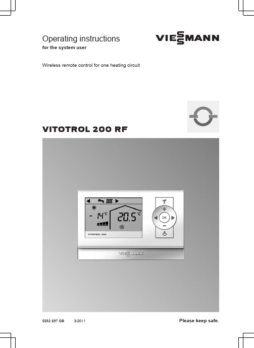
Operating instructionsfor the system userVIESMANNWireless remote control for one heating circuitVITOTROL 200 RF5592 697 GB 3/2011Please keep safe.2Please follow these safety instructions closely to prevent accidents and mate-rial losses.Safety instructions explainedDangerThis symbol warns against the risk of injury.!Please noteThis symbol warns against the risk of material losses and envi-ronmental pollution.NoteDetails identified by the word "Note" con-tain additional information.Target groupThese operating instructions are for the heating system user.This unit is not designed to be used by persons (including children) with limited bodily, sensory or mental capacities, or lacking experience and/or lacking knowl-edge, unless they are supervised by a person responsible for their safety, or have received instructions from such a person as to how to use the unit.!Please noteChildren should be supervised.Ensure that children do not play with the unit.DangerIncorrectly executed work on the heating system can lead to life-threatening accidents.■Work on gas appliances must only be carried out by a regis-tered gas fitter.■Work on electrical equipment must only be carried out by a qualified electrician.If you smell gasDangerEscaping gas can lead to explo-sions which may result in serious injury.■Do not smoke. Prevent naked flames and sparks. Neverswitch lights or electrical appli-ances ON or OFF.■Close the gas shut-off valve.■Open windows and doors.■Remove all people from the danger zone.■Notify your gas or electricity supplier and your heating con-tractor from outside the build-ing.■Shut off the electricity supply to the building from a safe place (outside the building).Safety instructions For your safety5592 697 G B3If you smell flue gasDangerFlue gas can lead to life-threat-ening poisoning.■Shut down the heating system.■Ventilate the boiler room.■Close all doors in the living space.In case of fireDangerFire creates the risk of burning and explosions.■Shut down the heating system.■Close the shut-off valves of the fuel lines.■Use a tested fire extinguisher,class ABC.Boiler room requirements!Please noteIncorrect ambient conditions can lead to damage to the heating system and put the safe opera-tion at risk.■Ensure ambient temperatures above 0 ºC and below 35 ºC.■Prevent air contamination by halogenated hydrocarbons (e.g. as contained in paints,solvents or cleaning fluids) and excessive dust (e.g. through grinding/polishing work).■Avoid continuously high humid-ity levels (e.g. through frequent drying of washing).■Never close existing ventilation apertures.Ancillary components, spare and wearing parts!Please noteComponents that are not tested with the heating system may lead to damage to the heating system,or may affect their various func-tions.Installation or replacement work must only be carried out by quali-fied personnel.Safety instructionsFor your safety (cont.)5592 697 G B4Introductory informationCommissioning.....................................................................................................5Terminology..........................................................................................................5Tips on saving energy (6)OperationOperating information...........................................................................................7Controls. (7)Central heatingRequired settings.................................................................................................9Setting the room temperature for standard heating mode.. (99)..............................................................1012121313" and "" are displayed. (131414)16 (18)Index Index5592 697 G B5Your remote control is connected to the Vitotronic control unit of the boiler by means of a wireless connection. The commissioning and adjusting of the Vitotronic control unit to local conditions and to the structural characteristics of the building, plus the instruction of the user in operating the system, must be carried out by your heating contractor.The settings made at the Vitotronic con-trol unit are transferred to the remote control during commissioning. The Vitotronic control unit is factory-set to "Heating and DHW".In other words, the rooms that you are controlling with your remote control are heated in accordance with the time pro-gram that has been set at the Vitotronic control unit, alternating between stand-ard and reduced room temperature.DHW heating will also take place in accordance with the settings from the Vitotronic control unit.Power failure■All data is saved if there is a power failure.TerminologyTo provide you with a better understand-ing of the functions of your remote con-trol unit, the appendix contains a chapter entitled "Terminology".Introductory informationCommissioning5592 697 G B6Use the setting options offered by the remote control:■Never overheat your rooms. Every degree by which the room temperature is reduced saves up to 6 % on heating costs.Never set your room temperature higher than 20 °C.■Select the heating program that meets your current requirements:–For short absences (e.g. shopping trips), select economy mode (see page 10).As long as economy mode is activa-ted, the room temperature is reduced.–In the summer, if you do not want to heat any rooms but require hot water, select the heating program–If you do not want to heat any rooms page 9).Further recommendations:■Correct ventilation.Briefly open windows fully and at the same time close the thermo-static valves.■Close roller shutters (if installed) at dusk.■Set thermostatic valves correctly.■Never cover radiators or thermo-static valves.■Controlled DHW consumption: A shower generally uses less energy than a full bath.Introductory information Tips on saving energy5592 697 G B7The Vitotrol 200 RF remote control unit enables the following adjustments to be made from the living space:■Standard room temperature ■Heating programAll other settings are transferred from the Vitotrol 200 RF to the Vitotronic control unit and vice-versa. The most recent adjustments always apply to your heat-ing circuit.Controls+Increases the standard room tem-perature.–Reduces the standard room tem-perature./You set the heating program.OK You confirm your selection or set-ting.You activate party mode.You activate economy mode.OperationOperating information5592 697 G B8A Header (heating program display)B Current outside temperatureC Current room temperature (actualroom temperature)Symbols on the display/DisplaysperatureHeating circuit pump runs Holiday program enabledIn conjunction with a solar thermal system:Solar circuit pump runs Operation Controls (cont.)5592 697 G B9If you want central heating, check the following points:■Have you set the required room tem-perature (set room temperature)?■Have you set the correct heating pro-gram?For settings, see the next chapter.Setting the room temperature for standard heating modeFactory setting: 20 °C Press the following keys:1.+/–for the required set room tem-perature.2.OK to confirm.The display shows the current room temperature (actual room temperature).Setting the heating programing (winter mode).Standby mode with frost protec-tion monitoringOnly DHW heating (summer mode)Central heating and DHW heating Press the following keys:1./the symbol for the current heat-ing program flashes.2./until the symbol for the required heating program flashes.3.OK to confirm.Central heatingRequired settings5592 697 G B10Selecting comfort modeWith this function, you can change the room temperature for several hours, e.g.if guests unexpectedly stay longer in the evening. With this function, DHW isboosted to the set temperature selected at the Vitotronic control unit.1. If you want to select a different room temperature during party mode:Set the required room temperature (see chapter "Setting the room tem-perature").NoteThis value is retained even after party mode is terminated.2. Press.Terminating the comfort function ■Press or■Automatically after 8 hours or■Automatically when the systemswitches to standard heating mode in accordance with the time program selected on the Vitotronic control unit.Selecting energy saving function "Economy mode"To save energy, you can reduce thebe shown on the display).For example, if you leave the house for a few hours.NoteEconomy mode cannot be selectedwhilst operating with reduced room tem-perature.Press.Comfort and energy saving functions Comfort and energy saving functions 5592 697 G BTerminating economy mode■Press or■Automatically when the systemswitches to reduced heating mode in accordance with the time program selected on the Vitotronic control unit.Comfort and energy saving functionsComfort and energy saving functions (cont.)5592 697 G BWhat to do if...Rooms are too cold5592 697 G BWhat to do if...There is no hot water5592 697 G BCauseRemedyThe batteries are spent.Change the batteries (see next chapter).The Vitotrol 200 RF has a power reserve.All set data is retained while the batteries are replaced.Changing the batteries■Use batteries of type Mignon LR6/AA,1.5 V.■Never use rechargeable batteries.Removing the VitotrolWhat to do if... is displayed5592 697 G BChanging the batteriesDisposalAlways dispose of spent batteries via an authorised collection site.What to do if...Changing the batteries (cont.)5592 697 G BSetback mode (reduced heating mode)See "Reduced heating mode".Heating programWith the heating program you determine whether you heat your rooms and DHW,or only heat DHW, or whether you shut down your heating system with frost pro-tection monitoring.You can select the following heating pro-grams:■The rooms are heated and DHW is■DHW is provided but there is no cen-tral heating (summer mode).■Frost protection is enabled; no central heating, no DHW heating.Operating statusing status changes from "Standard heat-ing mode" to the operating status"Reduced heating mode" and vice versa.The times for the operating statuschangeover are defined when the time program is set at the Vitotronic control unit.Heating circuitA heating circuit is a sealed circuit between the boiler and radiators, in which the heating water circulates.A heating system may comprise several heating circuits. For example, one heat-ing circuit for the rooms occupied by you and one heating circuit for the rooms of a separate apartment.Heating circuit pumpCirculation pump for the circulation of the heating water in the heating circuit.Actual temperatureCurrent temperature at the time of the scan; e.g. actual room temperature.MixerA mixer mixes the water heated in the boiler with the cooled water returning from the heating circuit. The water,heated to the right temperature in line with demand, is pumped to the heating circuit by the heating circuit pump. The Vitotronic control unit adjusts the heating circuit flow temperature via the mixer to suit the various conditions, e.g. different outside temperature.Night setbackSee "Reduced heating mode".Standard heating modeWhen you are in the house during the day, you can heat the rooms in standard heating mode. Set the periods with the time program for central heating at the Vitotronic control unit. During these peri-ods, the rooms are heated to the stand-ard room temperature.Appendix Terminology5592 697 G BStandard room temperatureWhen you are in the house during the day, set the standard room temperature (see page 9).Reduced heating modeWhen you are out or during the night, you can heat the rooms in reduced heating mode (setback mode). Set the periods with the time program for central heating at the Vitotronic control unit. Duringthese periods, the rooms are heated to a reduced room temperature.Reduced room temperatureWhen you are out or during the night,select the reduced room temperature on the Vitotronic control unit. See also "Reduced heating mode".Solar circuit pumpIn conjunction with solar thermal sys-tems.The solar circuit pump delivers the cooled heat transfer medium from the DHW cylinder indirect coil to the collec-tors.Set temperatureSpecified temperature that should be reached, e.g. set room temperature (see page 9).Summer modeHeating program "Only DHW".At warmer times of the year, i.e. when rooms do not have to be heated, you can disable heating mode. The boilerremains operational for DHW heating.Cylinder primary pumpCirculation pump for heating the DHW in the DHW cylinder.AppendixTerminology (cont.)5592 697 G BAActual temperature.............................16CCentral heating.....................................8Comfort function, party mode.............10Controls................................................7Cylinder primary pump.......................17DDay mode...........................................16Display elements..................................8EEconomy mode■Activating........................................10■Terminating.....................................11Energy saving function, economymode..................................................10FFactory pre-sets...................................5Factory setting.....................................5Fault message.....................................8Frost protection monitoring..................8GGlossary.............................................16HHeating and DHW................................5Heating circuit....................................16Heating circuit pump..........................16Heating mode■Reduced.........................................17■Standard.........................................16Heating program................................16MMixer (16)NNight mode.........................................16Night setback.....................................16OOperating information..........................7Operating procedure............................7Operating status.................................16PParty mode■Activating........................................10■Terminating.....................................10Power failure........................................5Programming unit.................................7Pump■Cylinder..........................................17■Heating circuit.................................16■Solar circuit.....................................17RReduced heating mode......................17Reduced room temperature...............17Rooms are too cold............................12Rooms are too hot.............................12Room temperature■Reduced.........................................17■Standard.........................................17SSaving energy■Economy mode...............................10■Tips...................................................6Setback mode..............................16, 17Set temperature.................................17Settings for central heating..................9Setting the heating program.................9Setting the room temperature..............9Solar circuit pump..............................17Standard heating mode......................16Standby mode (16)Keyword index Keyword index5592 697 G BStarting■Central heating.................................9■Comfort function.............................10■Energy saving function...................10Stopping■Comfort function.............................10■Economy mode...............................11Summer mode.........................9, 16, 17Symbols on the display........................8TTemperature■Actual temperature.........................16■Set temperature..............................17Terminology...................................5, 16WWater stays too cold..........................13Winter mode...................................9, 16Keyword indexKeyword index (cont.)5592 697 G BYour contactContact your local contractor if you have any questions regarding the maintenance and repair of your system. You may, for example, find local contractors on the internet under .Viessmann LimitedHortonwood 30, Telford Shropshire, TF1 7YP, GB Telephone: +44 1952 675000Fax: +44 1952 675040E-mail:*********************Viessmann Werke GmbH&Co KG D-35107 AllendorfTelephone: +49 6452 70-0Fax: +49 6452 5592 697 G B S u b j e c t t o t e c h n i c a l m o d i f i c a t i o n s.P r i n t e d o n e n v i r o n m e n t a l l y f r i e n d l y ,c h l o r i n e -f r e e b l e a c h ed p a pe r。
V3系列使用说明书20161220-1.1版

随附配件 ·············································································································3 安全须知 ·············································································································5
V3 系列视频多场景切换台
使用说明书 V1.1 △! 使用本 LED 视频处理器之前,请先仔细阅读此使用说明书并
将之妥善保存以备日后参考。 Before using this LED Video Seamless Switcher,please read this manual carefully and preserved for reference in the future.
MIG-V3 前后面板介绍························································································9
前面板介绍 ·········································································································9 后面板介绍 ·······································································································10 MIG-V3 主机板卡介绍 ······················································································11
爱德华消防主机EST3操作手册

E S T3火灾报警主机中文版操作手册第1章基本的系统操作概述本章叙述基本的系统操作指令。
内容面板控制显示信息处理显示开关的功能简介在本章所描述的操作系统中,必需确认每个事件。
每条信息可用“上一信息、下一信息”键查阅。
自动恢复(修复)的故障(Trouble)和状态(Monitor)等低优先权事件将被确认后自动地从信息队列中删去,而不必让操作员按复位(Reset)键,系统即可恢复正常工作。
注意:被清除后的报警(Alarm)和监视(Supvr)事件不能自动恢复,并将存于报警信息队列和监视信息队列中,直到人工按复位(Reset)键系统才能恢复正常工作。
面板控制面板控制开关的功能或者特点,其作用范围定义为,网络内当功能被激活时,火灾报警机箱受到影响的三种作用范围:·局部——其功能特性只影响安装了LCD显示屏的机箱·分组——其功能特性影响网络上预先定义好分组的机箱·全局——其功能特性影响网络上所有的机箱分组局部[3GROUP.CDR]└────────┬────────┘全局一个网络可以是一个或多个分组的一部分。
火灾报警系统配置的特性与功能因安装不同而异,可根据现场的特殊情况,来决定是否已经把用户需要的功能与特点设计进去。
LCD显示屏LCD显示屏是系统的主要的操作界面,它显示系统工作状态。
1.电源状态指示灯:当交流电源接通时绿灯亮。
(Power)2.测试状态指示灯:当系统的任何一部分处于测试状态时黄灯亮。
如果系统经过一段时间,没有(Test)动作,可编程的定时器会自动退出测试模式。
3.CPU故障指示灯:当中央处理器CPU的监视单元检测到处理器故障后,黄灯亮。
(CPU Fail)4.接地故障指示灯:当连接机箱的非接地线与地相连时黄灯亮。
(Ground Fault)5.屏蔽状态指示灯:当一些点或区域被人工屏蔽时黄灯亮。
(Disable)6.群呼开关/指示灯:按群呼键激活群呼功能。
3D3操作手册(精心整理)

3D3操作手册目录1.系统配置1.1 计算机配置1.2 相机配置1.3 投影仪配置2. 软件安装,注册激活及升级2.1 软件安装2.2 软件激活更新2.2.1 激活秘钥2.2.2 加密狗秘钥2.2.3 激活加密狗2.2.4 激活控软件狗3. 系统搭建3.1 3D扫描仪硬件搭建3.2 计算机设置4. 扫描仪标定4.1 创建/打开标定文件4.1.1 创建新的标定文件4.1.2 打开已有标定文件4.2 标定过程4.2.1 标定设置4.2.2 相机设置4.2.3 settings Calibration4.2.4 获取标定图像4.2.5 获得标定结果5. 获取扫描数据5.1 建立/打开新的工程5.2 转台设置5.3 数据扫描5.3.1 用转台扫描数据5.3.2 手动扫描6. 数据处理6.1 编辑网格6.2 网格操作6.3 数据拼接6.3.1 Alignment——对齐6.3.2 Combine——合并6.3.3 Uncombine——解除合并6.3.4 Finalizing Meshes6.4 数据的导入和导出6.4.1 数据导入6.4.2 数据导出第一章、系统配置3D3Solutions公司推出的FlexScan3D Scanner是一套集软硬件为一体的三维扫面仪,通过结构白光投影方式解析物体表面三维信息,Scanner由投影仪、相机、软件、以及一系列附件构成。
1.1计算机配置1.2相机配置(1)3D扫描仪入门级相机选型推荐方案(价格优先)·单相机扫描仪:PTGrey Chameleon CMLN-13S2M-CS·双相机扫描仪:IDS uEye UI-1545LE·镜头:Fujinon 12.5mm C-Mount Lens(2)3D扫描仪中级用户相机推荐方案(扫描速度优先,适用于扫描面部和人体特征)·130W双/多相机扫描仪:PTGrey FireWire Flea2 FL2G-13S2M or FL2-14S3M ·130W双/多相机扫描仪:IDS uEye GigE UI-5240CP·镜头:Fujinon 12.5mm C-Mount Lens(3)3D扫描仪逆向工程开发级相机推荐方案(精度、分辨率优先)·2M双相机扫描仪:PTGrey Grasshopper GRAS-20S4M-C·2M双相机扫描仪:Duo scanner setup: IDS uEye GigE UI-6250SE·镜头:5MP Fujinon 12.5mm C-Mount Lens1.3投影仪配置最低分辨率:800x600标准投影仪:1500+流明基于DLP(Digital Light Procession)技术LED投影仪:100+流明对比LED投影仪和普通正常投影仪:(1)LED投影仪优势:发热低;体积小巧;使用寿命长 (LED投影仪30,000小时,普通白光投影仪 3,000小时)(2)LED投影仪劣势分辨率、扫描精度、数据质量比较低;低光照,在复杂环境光影响下无法扫描;扫描黑色物体和高对比物体比较困难;选型局限性大。
SANTOS Santosafe N°37 厨房搅拌机 用户和维护手册说明书

SANTOS: User and maintenance manualUSER AND MAINTENANCE MANUALIMPORTANT: documents included in this manual to be kept:• "CE" COMPLIANCE DECLARATION • WARRANTY CERTIFICATETranslation of the original versionRead the instructions for use before unpacking the appliance.Coffee grinders - Fruit juicers - Mixers - Blenders - Drinks dispensers - Planetary mixers Cheese graters - Ice crushers - Mincers - Vegetable slicers – Dough mixerMoulins à café – Presse-fruits - Mixers – Blenders – Distributeurs de boissons –Batteurs mélangeurs - Pétrin – Râpes à fromage – Broyeurs à glaçons – Hache-viande – Coupe-légumesMODELES DEPOSES FRANCE ET INTERNATIONALINTERNATIONALLY PATENTED MODELSSANTOS SAS :140-150 AVENUE ROGER SALENGRO69120 VAULX-EN-VELIN (LYON) - FRANCEPHONE 33 (0) 472 37 35 29 - FAX 33 (0) 478 26 58 21 - E-Mail:****************www.santos.frKITCHEN BLENDER SANTOSAFE N°37CONTENTS“CE/EU” COMPLIANCE DECLARATION (3)SAFETY RULES (4)INSTALLATION AND HANDLING (4)DO NOT: (4)ELECTRICAL CONNECTION: (5)1st TIME USE (6)RECYCLING THE PRODUCT AT THE END OF ITS SERVICE LIFE (6)DESCRIPTION OF APPLIANCE (7)USING THE APPLIANCE (7)USING FOR THE 1st TIME: (7)Locking the jar clamping rod: (7)Operation: (8)Stopping the appliance: (8)Rotation speed: (8)Mixing solid foods: (8)Ice: (8)Making a mayonnaise: (8)RECOMMENDATIONS WHEN MAKING HOT PREPARATIONS: (9)CLEANING (9)MAINTENANCE (10)Changing the coupling system: (10)Spare parts: (11)Prolonged periods of non-use: (11)FAULT FINDING (12)The machine will not start: (12)The appliance stops following an overload: (12)The motor runs but the blades do not rotate: (12)APPLIANCE TECHNICAL SPECIFICATIONS (13)Electrical wiring diagram: (15)220-240V 50/60Hz wiring diagram (15)Figures (16)WARRANTY CERTIFICATE (17)APPLIANCE IDENTIFICATION PLATE (17)“E C/EU” COMPLIANCE DECLARATIONTHE MANUFACTURER:SANTOS SAS - 140-150, Av. Roger SALENGRO 69120 VAULX-EN-VELIN (LYON) FRANCEdeclares that the appliance intended for the professional market described below: Description: MIXERType number: 37complies with:•the statutory provisions defined in appendix 1 of the European "machines" directive n°2006/42/EC and the national legislation transposing it•the statutory provisions of the following European directives and regulations: o N° 2014/35/EU (low voltage directive)o N° 2014/30/EU (EMC directive)o N° 2011/65/EU (RoHS directive)o N° 2012/19/EU (WEEE directive)o N° 1935/2004/EC (regulation) relating to materials and articles intended to come into contact with foodstuffso N° 10/2011/EU (regulation) plastic materials and articles intended to come into contact with foodHarmonised European standards used to give presumption of conformity with the essential requirements of the above-mentioned directives:•NF EN 12852+A1: 2010, Food processing machinery –Food preparation equipment and blenders - Safety and hygiene requirements.This European standard is a type-C standard as defined in EN ISO 12100. When the provisions ofthis type-C standard differ from those stated in the type-A or B standards, the provisions of the type-C standard override the provisions of the other standards. This standard provides the means tocomply with the requirements of the "machines" directive n°2006/42/CE, (see appendix ZA) •NF EN ISO 12100: 2010: Safety of machinery - General principles for design•NF EN 60204-1: 2018: Safety of machinery - Electrical equipment of machines-General requirements•NF EN 1672-2: 2020, Food processing machinery – Basic concepts – Hygiene requirements•NF EN 60335-1: 2013 Safety of household and similar electrical appliances•EN 60335-2-64:2004 Part 2-64: Particular requirements for commercial electric kitchen machines.Drawn up in VAULX-EN-VELIN on: 01/02/2022Signatory’s position: CHIEF EXECUTIVE OFFICERSignatory’s name: Aurélien FOUQUETSignature:SAFETY RULESAt the time of use, maintenance or scrapping of the appliance, always ensure that the following elementary precautions are adhered to.Read the explanatory instructions in fullKeep this user manualINSTALLATION AND HANDLINGIt is prohibited to hold the appliance by the rod (1) or locking lever (2) The appliance can be installed by one person alone.For ease of use, you are advised to place the appliance on a table or work surface to easily add the ingredients or to monitor the progress(recommended height: 90 cm, to be adapted as required for the user).DO NOT:1. Plunge the base in water or any other liquid for reasons of protection against risks of electrocution.2. Use this applicable to blend, grind or emulsify anything other than foodstuffs3. Pass the pits through the appliance. Remove the pits from fruits before passing them in the appliance (e.g. mangos, apricots, peaches).4. The appliance is not designed for processing frozen foods.5. Do not insert solid ingredients into the mixer before switching it on.6. Do not operate the appliance with the jar empty.7. Do not remove the jar until the blades have stopped completely. 8. Never leave water permanently in the jar.9. Neither a water spray or a pressure spray should be used for cleaning 10. Never attempt to change the blades with the jar on the base.11. Be careful not to get burnt when preparing hot products. The surfaces of the jar and lid may be very hot12. Insert or store kitchen utensils in the jar.13. Operate the appliance if the jar or a blade is chipped, cracked or broken. Never use a jar if there is any play with respect to the blade.14. It is forbidden to operate the appliance on a surface with a slope in excess of 10° relative to the horizontal plane. All 5 feet of the appliance must always be resting on this surface.15. Use of spare parts other than certified original SANTOS parts is prohibited.!!Note: You will find it easier to understand the next few paragraphs if you refer to the diagrams at the end of this manual.16. use the unit with a damaged power cord. it must be replaced by anauthorized dealer or by SANTOS company, or by similarly qualified personsin order to avoid a hazard.17. The appliance must be unplugged before any intervention on it: cleaning,general care, maintenance.18. Connect several appliances to the same power socket.19. Use the appliance outdoors.20. Never place the appliance close to or on a source of heat.21. This appliance is a professional machine designed exclusively forprofessional use. It is not designed for household use.22. This appliance is not designed for use by people (including children) whosephysical, sensorial or mental capacities are impaired or by people with noexperience or knowledge, unless they have been supervised or given trainingin the use of the appliance beforehand by a person responsible for theirsafety.Supervise children to ensure they do not play with the appliance.23. This appliance is intended for use in communal areas, e.g. in the kitchens ofrestaurants, canteens, hospitals and artisan trades such as bakeries,butcher's shops, etc., but not for continuous mass production of food.ELECTRICAL CONNECTION:•The appliance's power supply is available in two single-phase voltages:-100-120 V 50/60 Hz:-220-240 V 50/60 Hz:Note: This appliance can operate at both 50Hz and 60Hz without any adjustments.Line protection: the appliance must be connected to a standard 2 pole + earth socket. The set-up must be fitted with a differential circuit breaker and a 16A fuse. Earthing of the appliance is compulsory.TAKE CARE:•Before connecting the appliance, check that the mains electrical voltage is the same as the voltage for your appliance. Its value is shown:!➢either on the identification plate under the appliance.➢or on the identification plate on the last page of this manual.•If the power cord is damaged, it must be replaced by an authorized dealer or by SANTOS company, or by similarly qualified persons in order to avoid a hazard.TAKE CARE: Check that the on / off switch (3) is in position “OFF” beforeplugging the power cord in to the mains power socket.1st TIME USE!Be careful not to get cut when handling the blades or cleaning insidethe jar.Thoroughly clean all parts in contact with the food.Wash the following with a standard dish washing product: jars (6), lids (7), caps (8).You are not advised to wash the lid seal (9) and the blade seal (16) in a dishwasher. RECYCLING THE PRODUCT AT THE END OF ITS SERVICE LIFEThis appliance is marked with the symbol of the selective waste sortingsystem relating to waste electrical and electronic equipment. This meansthat this product is covered by a selective sorting system in compliance withthe 2012/19/EU Directive (WEEE) - part relating to appliances forprofessional use - so as to be either recycled or dismantled with a view toreducing any impact on the environment.For further information, you can contact SANTOS or your local dealer.For the disposal or recycling of the appliance components, please refer to a specialist company or contact SANTOS.Electronic products not covered by a selective sorting system are potentially dangerous for the environment.The packaging material should be disposed of or recycled in accordance with regulations in force.DESCRIPTION OF APPLIANCEMixer N° 37 is an electrical appliance designed to blend, grind and mix different foodstuffs in the form of liquids, doughs/batters or solids. The most common applications relate to the following preparations:• COOKING : soups – cream soups - sauces - creams - mousses - purées - pâtés - soufflés...• DESSERTS : creams – stewed fruit - batters - milk-shakes - flans - mousses... • DRINKS : fruit, vegetable cocktails - punches - syrups - sangria.USING THE APPLIANCEDo not operate the appliance with the jar empty.USING FOR THE 1st TIME:Locking the jar clamping rod:For your safety, the appliance can only operate when the jar (6) is closed by its lid (7) and correctly positioned on the base (4).Push the handle (2) down to lock or then down again to unlock the jar clamping rod (1).When in the unlocked position (rod in top position), place the jar closed by its lid on the base (4).Push the handle (2) down to lock the jar (6) (rod in lower position). Turn the rotary switch (3) to start up the motor and set the desired speed.!17642315Handle in Locked positionHandle in Unlocked position2Operation:The mixer must always operate with a minimum of liquid in the jar in order to drive solid foods towards the blades.Maximum speed with rotary switch: 15,000 rpmSpeed with PULSE button: 18,000 rpmStopping the appliance:There are two ways to stop the appliance:1. Turn the rotary switch (3) to "OFF" to stop the motor completely, then operate thehandle (2) to release the jar. Wait until the blades have stopped completely beforeremoving the jar from the base.2. During operation at a set speed, push the handle (2) down to unlock the clamping rod(1). This operation will stop the appliance without altering the speed adjustment.Wait until the blades have stopped completely before removing the jar from the base.Rotation speed:The rotation speed of the blades must be adapted to the results desired and the type of foodstuffs to be processed.Mixing solid foods:Dice up dry ingredients and insert them through the opening in the lid (7) when the appliance is in operation.Increase the size of the cubes according to the quantity of food already mixed or "puréed" in the jar.Ice:Do not use the blades to crush blocks of ice.Small ice cubes like those produced by the majority of automatic ice makers can be crushed at low speed.Making a mayonnaise:Put all the ingredients in the jar except for the oil. During operation, remove the cap (8) from the lid and add the oil a little at a time pouring it in evenly.RECOMMENDATIONS WHEN MAKING HOT PREPARATIONS:In order to optimise the operation and safety of the appliance, you are advised to: •Fill the jar according to its functional capacity and not its total capacity•Do not use the pulse button at the start.•Gradually increase the mixing speed.•Replace the blade and lid seal every 6 months when making hot preparations.The seal may loosen when in contact with very hot food and lead to a leakageproblem over time.CLEANINGBe careful not to get cut when handling the blades or cleaning inside the jar.IMPORTANT:•Stop the appliance and unplug the power cord from theappliance.•The appliance should neither be cleaned in a water spray nor !with a pressure spray•The motor unit (4) must not be immersed in water.•Do not use an abrasive sponge to clean the plastic jar (6).•Do not hermetically close the jar when the appliance is stored away(remove the cap (8) from the lid).You are advised to clean the appliance as soonas you have finished using it.It will be easier to clean if you do not allow theremaining scraps of food to dry.For thorough cleaning, take apart the parts of the jar(unscrew the jar (6) from the handle base (5)) andwash them with hot soapy water, rinse and dry.The base can be cleaned using a soft, wet sponge.6Unscrewing75 9MAINTENANCEPrior to carrying out any intervention on the appliance, it must be disconnected from the mains without fail.Changing the coupling system:When changing the couplings, make sure you adhere to the position of each component:• flexible coupling (11) on the motor unit • rigid coupling (12) on the blade holder.IMPORTANT: Motor end:Turn the screw (13) counter clockwise to remove the flexible coupling (11). Blade end:Turn the screw (14) counter clockwise to remove the rigid coupling (12).REMARKS: for N°37 versions prior to 2012, screw (13) must be turned clockwise to remove the flexible coupling (11).!Loosening direction of fixing screw, motor end: counter clockwise Loosening direction of fixing screw, jar end: counterclockwise14 12 11 13Spare parts:IMPORTANT: use of spare parts other than certified original SANTOS parts !is prohibitedThis machine requires no specific maintenance. The bearings are lubricated for life.If any intervention is necessary to replace parts subject to wear, such as the couplings, blades, jar seals, electrical or other components, please refer to the parts lists (see the exploded view at the end of this manual).For all spare part orders (see references in the exploded view at the end of the manual), state:➢the type➢the appliance serial number and➢the electrical specificationsgiven under the appliance.Prolonged periods of non-use:There are no problems with this appliance in the event of prolonged periods of non-use. You are simply advised to clean it before use and check that the components of the appliance are in good condition (e.g. power cord, seals and other spare parts).FAULT FINDINGIdentifying the cause of appliance stoppage with precision.If the problem persists, switch off the power supply to the appliance (unplug the cord from the mains socket) and call in the maintenance service or contact a SANTOS approved dealer.The machine will not start:•Check : the mains supply, the condition of the power cord•To run the motor of the mixer the jar (6) with its lid (7) closed must be placed on the base(4) and locked using the clamping rod (1).•Check that there is no food that is too hard or big jamming the blades (10).The appliance stops following an overload:•If the motor stalls during operation, reduce the load, allow the appliance to cool down for several tens of minutes.•Check that there is no food that is too hard or big jamming the blades (10).The motor runs but the blades do not rotate:•Check the condition of the coupling system. If required, change the 2 parts at the same time.(see "maintenance” section)APPLIANCE TECHNICAL SPECIFICATIONSModel n° 37Power supply voltage (V) 220-240Frequency (Hz) 50/60Motor (1)Input power (W) 1550Max. current (A) 8Speed (rpm) 0 to 18000Operating cycle (3) Intermittent Cycle:10min ON/10min OFF2L jar capacity (L) 1.54L jar capacity (L) 3Dimensions: Height (mm) 566Width (mm) 220Depth (mm) 303Weight: Net weight (kg) 12Packaged weight (kg) 14Noise: (2) L pAaccuracy K pA = 2.5dB(dBA) 66(1) These ratings are given for your guidance. The exact electrical specifications of your appliancecan be found on the rating plate.(2) Noise level measured in acoustic pressure of appliance loaded as per the standard ISO11201:1995 and ISO 4871:1996.Appliance placed on a work surface at 75cm from the floor. Microphone turned towards the appliance at 1.6 m from the floor and 1 m from the appliance.(3) Operating cycleThe professional appliance is designed for intermittent use according to an intermittent cycle of10 minutes on, 10 minutes off.This cycle corresponds to the operating time to perform the function and the stopping time for the preparation and serving of the products processed, in compliance with the instructions of the standard: EN 60335-2-64+A1:2004 Part 2-64: Particular requirements for commercial electric kitchen machines.ITEM Description1 Clamping rod2 Locking handle3 Switch, speed adjustment4 Motor unit5 Jar handle6 Jar7 Lid8 Cap of lid9 Lid seal10 Blade assembly11 Flexible motor coupling12 Rigid jar coupling13 Motor coupling screw14 Blade coupling screw15 PULSE button16 Blade sealElectrical wiring diagram:220-240V 50/60Hz wiring diagramFGBDNEIJAUNE YELLOW GELB GEEL AMARILLO GIALLO BLANC WHITE WEISS WIT BLANCO BLANCO NOIR BLACK SCHWARZ ZWART NEGRO NERO BLEU BLUE BLAU BLAUW AZUL BLU ROUGE RED ROT ROOD ROJO ROSSO MARRON BROWN BRAUN BRUN MARRON MARRONE ORANGE ORANGE ORANGE ORANJE NARANA ARANCIONE VIOLET VIOLET VIOLETT VIOLET VIOLETA VIOLA GRISGREYGRAUGRIJSGRISGRIGIOVERT/JAUNEGREEN/YELLOWGRÜN/GELBGROEN / GEELVERDE/AMARILLOVERDE/GIALLOMOTEURVert Rouge BlancGris MarronBlancUNITE ELECTRONIQUE DECONTROLEPotentiomètre Réglage de vitesseFILTRE ANTI -PARASITES220-240 V ~MarronNoirBlancGrisViolet OrangeViolet OrangeGris Blanc PulseMarronNoir Interrupteur manetteNoir Marron NoirBlanc OrangeGris GrisVert/jauneVert/jauneBlanc12 JauneRougeFigures5213978 4 61015106579 87Loosening direction of fixing screw, motor end: counterclockwiseLoosening direction of fixing screw, jar end: counterclockwise1412 1113WARRANTY CERTIFICATEWARRANTYSince the 01.01.95, all our appliances comply with CE and possess the CE label. Our guarantee is of 24 months from the manufacturing date mentioned on the descriptive plate, except concerning the asynchronous motors (consisting of a rotor and a stator) which are warranted for 5 years from their manufacturing date. Warranty is strictly limited to the free replacement of any part of origin recognized by us as defective due to a defect or building default and identified as belonging to the concerned appliance. Warranty does not apply to damages resulting from installation or use non-complying with our appliance data sheet (user’s manual) or in case of an evident lack of maintenance or disrespect of elementary security electric rules. It does not apply in case of regular wear and tear.Any replacement of parts under warranty will be realized after return of the defective part in our workshops, postage paid, supported by a copy of a conformity statement on which appears the serial number of the appliance. Every appliance is equipped with a descriptive plate conforming to the EC recommendations and of which a duplicate exists in the conformity statement (serial number, manufacturing date, electrical characteristics …). In case of serious damage judged repairable only in our workshops, and after prior consent from our departments, any appliance under guarantee is sent by the Distributor, carriage paid. In case of repairs or reconditioning of appliances not under guarantee, the round trip transport is payable by the distributor. The parts and workforce are invoiced at the current rate. A preliminary estimate can be supplied.Coffee grinder not using SANTOS original burrs are not taken under guarantee. The warranty conditions, repairs, reconditioning, of the espresso coffee grinder are the object of a specific note. Our guarantee does not extend to the payment of penalties, the repair of direct or indirect damages and notably to any loss of income resulting from the nonconformity or the defectiveness of products, SANTOS's global responsibility being limited to the sale price of the delivered product and to the possible repair of the defective products.In case of revelation of an imperfection during the warranty period, the Distributor has to, unless a different written agreement of SANTOS, indicate to his customer to stop any use of the defective product. Such a use would release SANTOS of any responsibility.APPLIANCE IDENTIFICATION PLATESPECIMENFor all documents not supplied withappliance.Printed, Faxed, Downloaded。
igloohome 智能钥匙盒3用户手册说明书

1Welcome!This guide will get you up and running with your igloohome Keybox 3. In the meantime, you should follow igloohome on Facebook and Y outube!Like us on FacebookVisit our Y outubeTable of ContentsInc luded 4What’s5c ationsc ifiSpeFeatures 6QuiGuide 8 Startc kOnboarding 9 Appc essinApp 10 cManagingAc king 11Unloc king 12Loc kInstallation 13 LoBehaviour 15 c kLoJumpstart 16 USB-CAudio and LED Indications 1718 Troubleshoot4What’s IncludedKeybox 3Mounting Screws x2Screws Anchors x2Slim ShackleMounting Seal Rings x2Screwdriver5Model igloohome Smart Keybox 3Battery Type 4 x AAA Alkaline Batteries Battery Life Up to 12 months Emergency Power USB-C Jumpstart Operation Temp -20°C to 50°C IP Rating IP66 Body Material Zinc Alloy, Aluminium Alloy, Acrylic Shackle Material Hardened Steel, Rubber Weight Net: 1kg, Gross: 1.3kg Unlock Mechanism Bluetooth, PIN codeSpecificationsFront* DO NOT USE: Heavy Duty, Eveready, GP, or rechargeable batteries. Duracell & Energizer alkaline batteries recommended. Please note that using better batteries will improve the performance and lifespan of the lock.Storage Depth : 27 mmFront (Opened)114 mmThickness: 53mm30 mm6Low Battery IndicatorThe Status Indic ator shows red light when battery level is 20% and below, followed by a sound alert when the keypad is woken up. The battery level can also be monitored on the app and is updated during Bluetooth Unlock.Battery LifeThe Keybox 3 c an last up to 12 months with 4 AAA Alkaline battery.Emergency Jump StartIf battery power is drained, connect a USB-A to USB-C cable to a power bank then plug it onto the USB-C jumpstart port on the keybox toprovide emergency power.Bluetooth Master KeyThe igloohome Keybox 3 unlocks with Bluetooth via the app.Master PIN CodeThe igloohome Keybox 3 unlocks with a permanent Master PIN Code.User PIN CodeThe igloohome mobile app c an generate multiple types of User Pin c odes, e.g. One-Time, Permanent & Duration.Bluetooth Guest KeyThe igloohome mobile app c an generate and share Bluetooth keys based on duration with guests to unlock the Keybox 3.PIN / Bluetooth UnlockBattery7Masking Security CodeA total of 16 digits inc luding the masking digits c an be entered to prevent the PIN c ode from being exposed.Auto RelockThe Keybox 3 relocks automatically when product is closed. User can deactivate auto-relock function if they prefer manual relock.Keypad Security LockoutLoc k will disallow any PIN entries and sound an alarm when there is a number of incorrect PIN attempt. User c an c onfigure number of in c orre c t attempts to trigger timeout.SecurityWeather ResistantThe Keybox 3 is able to withstand weather conditions with protection against dust and water (IP66).8Loosen the 4 screws and remove battery coverInsert AAA BatteriesSecure battery cover tightly with 4 screwsBattery CoverPlease screw the battery cover tightly after inserting batteries to ensure optimal water resistance.9App OnboardingIn the factory mode (before pairing), the PIN to unlock the lock is 1 2 3 4 5 6 7 8 9 0Test Factory PIN Unlock2Register as a Lock Usera) Download igloohome from the App Store / Play Store b) Create an account and login3Pairinga) Select [Add new igloohome lock]Note: For existing users with other paired locks, go to [Configuration], select [Add Locks] and follow the instructions.Setting Master PIN Code4Before proceeding, turn on your Bluetooth and ensure that you are within Bluetooth range of the lock.Go to [Access] and customize your [Master PIN] by editing it.10Managing Access in AppPIN codes can be generated on the app under [Access], press [+Access] and choose either One-Time, Permanent or Duration PIN.Pin codes will expire if its not use within its activation period. Refer to the table below.Note: Duration PIN code end times can be customised within a 28-day timeframe. Past this timeframe, the end time will automatically be configured to the start time.Creating PIN codes2Bluetooth Guest KeyPIN Type Use PIN within*Permanent PIN 24 hrs of generation One-Time PIN 24hrs of generation Duration PIN24hrs from the start timeBluetooth Guest Key can be shared with other users for mobile access. It allows your guests to unlock the igloohome smart lock via Bluetooth. There are 3 steps to using a Shared Bluetooth Key1. Under [Access], press [+Access] and choose [Bluetooth Key] under [Access Type]. Proceed to share the key after it is created.2. Guest receives the Bluetooth Key by one of these methods: • Clicking the URL given and follow the instructions. • Claiming Bluetooth Key under [Configuration].3. Guest can now use the Bluetooth Key under the Guest Bluetooth Key Section whenever he/she is within range of the lock.Notes: • The owner can revoke the Bluetooth Key in App.•Bluetooth Key must be accepted within 1 hour generation before it expires.UnlockingBluetooth Unlock1. Open your igloohome app2. Tap on the “Bluetooth Unlock” button3. The status indicator will flash green twice with 4 short ascending tone once unlocked.PIN Code1. Press any button on the keypad to wake device up2. Key in a valid PIN code (with or without masking pins) followed by the “Unlock Icon”3. The status indicator will flash green twice with 4 shortascending tone once unlocked.Locking Auto RelockSimple close the keybox in place and Status Indicator will show green with a long beep. Manual Relock Press and hold the Unlock icon on the bottom right of the keypad for 2 seconds until the status indicator will show green with a long beep.Note: Used when Auto Relock is “Off”Secure Keybox on a handle or knob1. Unlock the keybox2. Push the shackle release to the right3. Pull out the shackle4. Secure on a handle or knob5. Insert back the shackleFor door knobs,use Slim Shackle For door handles,use Regular Shackle Lock InstallationMount on a surface1. Unlock the keybox2. Drill holes on a wall3. Hammer the screw anchors into the holes4. Mount the Keybox 3 on the wall with the mounting seal rings and 2 screwsNote: User is able to Enable and Disable Keypad Security Lockout via Bluetooth.Lock Behaviour1. Connect the USB-A to USB-C cable to a power bank then plug it2. While the USB-A to USB-C cable is connected to the power bank,USB-C Jumpstartonto the USB-C jumpstart port on the keybox.key in PIN code on the keypad followed by to unlock.USB-C Jumpstart FeaturePlease unlock by entering a valid PIN code or via the app within 20 seconds after the keybox is powered up.Audio and LED IndicationsTroubleshootI am unable to close the keybox. • Do an unlock via PIN code or Bluetooth and try to close the keybox again.• Note that you might accidentally lock the keybox manually by holding the UNLOCK button for 2 seconds when the keybox is open.• Do a Bluetooth Unlock or sync and try again.• Make sure that the generated PIN codes are activated within the activation period before it expired.I have generated my PINs from the app but it cannot work.• The Keybox is low in battery.• Use an USB-A to USB-C cable connected to a power bank to jumpstart the lock and unlock the Keybox to replace the batteries.• Refer to page 8 to know how to replace batteries.I tried to unlock the Keybox but the keypad went off and came back on with 2 slow and 2 quick beeps. • The Keybox’s battery is flat. • Use an USB-A to USB-C cable connected to a power bank to jumpstart the lock and unlock the keybox to replace the batteries.• Please unlock within 20 seconds. • Refer to page 8 to know how to replace batteries. The lock is not responding at all.• Use the spare QR sticker that is provided in the Keybox box.I can’t scan the QR sticker as it is worned out.• Make sure Auto Relock is ON via the igloohome mobile app.• If Auto Relock is ON and the keybox is still not working, try to lock the keybox manually by holding the UNLOCK button for 2 seconds.I closed the Keybox but it did not relock automatically.• Note that the screws are designed to be retained, therefore cannot be removed. • Please loosen the screws to remove the battery cover. I am unable to remove the battery cover screws.• Keypad Security Lockout is triggered on the Keybox. • Please refer to page 15.The keybox keypad flashes white and LED indicator flashes red when I activate the keypad.• Please ensure USB-C connector is connected to the USB-C slot securely while unlocking it with PIN code or Bluetooth.• Please unlock within 20 seconds.• Please ensure that the Power Bank has sufficient power. I tried to use USB-C to jumpstart the lock but unable to.。
英国森威尔集团(香港) 专业楼宇控制器 Step3 说明书
英国森威尔集团(香港)有限公司请您先简单浏览向导,很快就了解STEP3概要。
目录一、STEP3向导 (2)二、技术参数 (3)三、STEP3操作使用说明 (8)(一)设置模式 (8)1、密码输入 (8)1、密码修改 (9)2、地址码设置 (9)3、波特率设置 (10)4、测量范围设置 (10)5、模拟量输出(AO1-AO16)限幅设置 (11)6、死区设置 (11)7、AO输出组态 (11)8、DO输出组态 (12)9、时间设置 (15)10、测量补偿设置 (15)11、报警设置 (15)12、AO设定值设置 (16)13、DO设定值设置 (16)(二)工作模式 (16)(三)虚拟变量 (17)四、STEP3通讯协议 (18)(一)通讯口设置 (18)(二)通讯传送方式 (19)(三)上位机与STEP3通讯 (20)五、应用示例 (27)六、STEP3编程说明 (28)七、STEP3配套软件介绍 (31)八、常见问题诊断 (32)一、STEP3向导1. STEP3是一个面向中央空调和楼宇系统(BAS )的DDC 控制器,采用工业现场总线,高度可靠。
也可以用于工厂动力设备联网监控。
2. STEP3外观精致美观。
3. STEP3博采众长,通过CE 认证,至今已在200多个项目上稳定运行。
4. 豪华的二次开发编程软件完全免费。
也可以通过键盘组态,获得发明专利(专利号:200510035500.X )。
5. 比同类产品节省30%~50%的投资。
6. 可以通过串口下载程序,也可以通过现场总线远程下载。
7. 同样免费的STEP3-DEBUG 在线仿真软件,用于验证你任意编制的控制逻辑是否正确。
8. 通用端口技术,AI 与DI 、AO 与DO 口可以相互转换,AI 口还可以灵活选择PT1000、NTC 、或0-10VDC 、4~20mA 传感器,完全通过软件设置。
应用示例一:用于控制组合式空调机组,实现恒温恒湿。
爱立信智能家居单点安装操作指南说明书

Control your fans from anywhere with Eaton’s Wi-Fi Smart Fan Speed Control (EWFFSC15) which replaces standard switches and features ON/OFF and DIM/BRIGHT control. The Wi-Fi Smart Fan Speed Control (EWFFSC15) can be remotely controlled using the Brightlayer Home App.Eaton’s Wi-Fi Smart Fan Speed Control has additional features such as a selection of 3 fan speed controls (High, Medium, Low).Your Wi-Fi Smart Fan Speed ControlFeaturesQuick StartSingle location installation Operation instructionsTools neededAdditional system requirementsPhillips-head ScrewdriverWire cuttersPrior to installationRequires neutral for installationWARNINGS AND CAUTIONS:• T urn OFF circuit breaker or remove fuse(s) and test that power is OFF before installation process • N ever wire any electrical device with power turned ON Wiring fan speed control HOT may cause permanent damage to fan speed control and void warranty • I f you are not sure about any part of these instructions, please contact a licensed electricianCAUTION• Use only with 120V/AC 60Hz• Do not exceed maximum rating of fan speed control as indicated on the device • M ust be installed and used in accordance with all national and local electrical codes • I f a bare copper or green ground connection is not available in the wallbox, contact a licensed electrician for installation • U se only #14 or #12 copper wire rated for at least 75ºC with these devicesDO NOT USE WITH ALUMINUM WIREIMPORTANT: Wi-Fi Smart Fan speed control (EWFFSC15) will not work or will be damaged if wired incorrectly and warranty will be voided. Refer to wiring instructions provided.NOTE: The Wi-Fi Smart Fan speed control (EWFFSC15) is wired directly to the ceiling fan fixture.• Press ON button to turn fan ON at previously selected level • Press the OFF button to turn the fan OFF • The bottom LED indicates the fan speed controller is turned ON• When fan is OFF, press and hold the ON button for 2 seconds until LED blinks green for full fan speedFACTORY RESET: The fan speed controller can be reset which will exclude the device from its network and restore all factory defaults.• Turn ON the fan speed controller • Press and hold the ON button for 30 seconds until the LED indicator blinks red• Release the button • LED indicator will start flashing fast while it is being reset • The LED indicator will then start blinking magenta at a normal rate indicating the fan speed controller is not part of a Wi-Fi networkScan for more advanced featuresincluding adjusting the brightness level of the LED indicators and additional wiring configurationsFor color change kit installation instructions, see back pageTools required for installation (not included) for the Wi-Fi Smart Fan speed control (EWFFSC15):A 2.4GHz Wi-Fi network with high-speed internetIOS 12.0 or later or Android 8.0 or later mobile device. Note: Must be connected to Wi-Fi and Bluetooth A Brightlayer Home account set-up through the Brightlayer Home AppCan be wired with standard 3-way switch where traveler wire exists for 3-way.Voice control w ith Alexa and Hey Google installation requiredSet schedules, groups, and scenesFan Speed Controller Rating - EWFFSC15Load TypeSingle Gang EWFFSC15Ceiling fan1.5ANeutral is requiredSingle pole & 3-way3 Preset fan speeds High, Medium, LowPress to speed upPress to slow downWi-Fi Smart Devices offer reliability with unbeatable ease o f setup. /smarthomeEWFSW15EWFTRCR15EWACDEWFFSC15Amazon, Alexa and all related logos are trademarks of , Inc. or its affiliates. Google and Google Play are trademarks of Google LLC. Wi-Fi CERTIFIED logo is a trademark of the Wi-Fi Alliance.by following the instructions on the screen.Select the device type to addNote: Now the user can utilize many features that areFold in half vertically with page 1 on outside, then Z-fold in horizontal direction to final folded size of 3.4 in. W x 5.5 in. H with part number facing outward.。
SweetHome3D教程
Sweet Home 3D 是一款免费、开源的家
装辅助设计软件。
它能帮您通过二维的家居平
面图来设计和布置您的家具,还可以用三维的
视角浏览整个装修布局的全貌。
如果您的手头
有现成的房型平面图,您可以将其导入为该软
件中的平面图背景,设定好比例后便可直接根
据图纸上的现有内容绘制墙体。
您对平面图所
作的任何更改将会实时地显示在3D 视图
中,所以您随时都可以查看逼真的效果图。
按住Ctrl单击此处进入 Sweet Home 3D 在线用户
手册(英语)。
与此同时,Sweet Home 3D 还提供了一套完备的离线帮助,可使用帮助→Sweet Home 3D
帮助菜单项打开。
Sweet Home 3D 视频教程
您可以通过观看下面的视频教程探索 Sweet Home 3D 的功能和用法
视频教程(按住Ctrl再点击)。
THPFSM-3型实训指导书
目录第一章可编程控制器简介 (2)第二章可编程控制器的编程规则 (6)第三章S7-300的自动化通信网络 (7)第四章编程软件的介绍及使用 (9)第二章实训项目 (17)实训一PLC认知实训 (17)实训二数码显示控制 (20)实训三抢答器控制 (23)实训四音乐喷泉控制 (26)实训五装配流水线控制 (28)实训六十字路口交通灯控制 (31)实训七水塔水位控制 (33)实训八天塔之光控制 (35)实训九自动配料装车系统控制 (37)实训十四节传送带控制 (40)实训十一多种液体混合装置控制 (43)实训十二自动售货机控制 (46)实训十三自控轧钢机控制 (48)实训十四邮件分拣机控制 (51)实训十五自控成型机控制 (53)实训十六机械手控制 (55)实训十七加工中心控制 (57)实训十八三层电梯控制 (60)实训十九四层电梯控制 (63)实训二十自动洗衣机控制 (66)实训二十一电镀生产线控制 (68)实训二十二步进电机控制 (71)实训二十三直线运动位置检测、定位控制 (73)实训二十四直流电机控制 (75)实训二十五温度PID控制 (77)实训二十六五相步进电动机控制 (79)实训二十七电机控制 (81)实训二十八变频器功能参数设置与操作 (83)实训二十九变频器无级调速 (88)实训三十变频器报警与保护功能操作 (90)实训三十一外部端子点动控制 (92)实训三十二变频器控制电机正反转 (94)实训三十三多端速度选择变频器调速 (96)实训三十四外部模拟量方式的变频调速控制 (98)实训三十五瞬时停电启动控制 (100)实训三十六PID变频调速控制 (102)附录:THPFSM-3型网络型可编程控制器综合实训装置使用说明书 (104)第一章 可编程控制器简介随着微处理器,计算机的和数字通讯技术的飞速发展,计算机控制技术已经渗透到所有工业领域。
当前用于工业控制的计算机可分为:可编程控制器,基于PC 总线的工业控制计算机,基与单片机的测控装置,用于模拟量闭环控制的可编程调节器,集散控制系统(DCS)和现场总线控制系统(FCS)等。
三维沉浸式虚拟家装平台-需求规格说明书

实用标准装扮家-三维沉浸式虚拟家装平台需求规格说明书文档记录*变化状态:C――创建,A——增加,M——修改,D——删除目录目录 (4)1引言 (6)1.1背景 (6)1.1.1待开发产品名称 (6)1.2参考资料 (6)1.3术语、缩略语 (6)2概述 (7)2.1产品目标 (7)2.2整体结构 (7)3用户视图 (9)3.1总结构 (9)3.2产品需求列表 (9)3.3需求分析 (10)3.3.1一级子模块-选房型 (10)3.3.2一级子模块-选家具 (11)3.3.3一级子模块-选工长 (12)3.3.4一级子模块-3D装扮 (13)3.3.5一级子模块-购物车 (13)4厂商视图 (14)4.1总体结构 (15)4.2产品需求列表 (15)4.3需求分析 (15)4.3.1一级子模块-产品管理 (15)4.3.2一级子模块-案例管理 (16)4.3.3一级子模块-联系客户/处理订单 .................... 错误!未定义书签。
5工长视图 .. (17)5.1总体结构 (17)5.2产品需求列表 (17)5.3需求分析 (18)5.3.1一级子模块-装修案例展示 (18)5.3.2一级子模块-联系客户/处理订单 (18)6非功能性需求分析 (20)6.1数据缓存 (20)6.2请求数据的时机 (20)6.3数据同步机制 (21)6.4程序性能 (21)1引言1.1背景装扮家-三维沉浸式虚拟家装平台旨在打造一个家装行业平台,为家具厂商,家装用户,室设计师,施工人员等行业相关人员建设一个信息交流平台,让家具厂商更便捷的推广主打产品,让室设计师更真实的设计家装,让用户减少装修视觉误差,提高装修效率,改善家装体验。
装扮家-三维沉浸式虚拟家装平台计划分为三个阶段开发,第一阶段计划开发web端产品,实现3D家具选配和沉浸式体验等核心功能;第二阶段计划开发安卓端和IOS端程序,改善web端用户体验和视觉体验;第三阶段计划开发在线支付全流程,建立完整用户,厂商,工长的角色行为闭环。
- 1、下载文档前请自行甄别文档内容的完整性,平台不提供额外的编辑、内容补充、找答案等附加服务。
- 2、"仅部分预览"的文档,不可在线预览部分如存在完整性等问题,可反馈申请退款(可完整预览的文档不适用该条件!)。
- 3、如文档侵犯您的权益,请联系客服反馈,我们会尽快为您处理(人工客服工作时间:9:00-18:30)。
...
3D
eTeks
Sweet Home 3D
3D
3D
Sweet Home 3D
/ ,
Sweet Home 3D version 3.7
/examples/userGuideExample.sh3d (3.2 MB).
Sweet Home 3D Windows, Mac OS X 10.4 / 10.8 Linux Solaris 23
Sweet Home 3D Sweet Home 3D
1. Sweet Home 3D
.
Sweet Home 3D:
Sweet Home 3D
2 Sweet Home 3D
2. Sweet Home 3D
Windows: /projects/sweethome3d/files/SweetHome3D/SweetHome3D-3.7/SweetHome3D-3.7-windows-oc.exe/download (32.7 MB)
Mac OS X: /projects/sweethome3d/files/SweetHome3D/SweetHome3D-3.7/SweetHome3D-3.7-macosx.dmg/download (16.2 MB)
Sweet Home 3D Sweet Home 3D
Linux: /projects/sweethome3d/files/SweetHome3D/SweetHome3D-3.7/SweetHome3D-3.7-linux-x86.tgz/download (52.8 MB)
SweetHome3D
1
3
2
4
2 Tab Shift + Tab
3 Mac OS X Sweet Home 3D > ...
> ...
3
Sweet Home 3D
1. 2.
3. 4.
5. 3D ,
6.
7.
8.
3D
Sweet Home 3D
.
Sweet Home 3D
3D
3D PNG OBJ+MTL
4 > ...
5
> ...
5.
ESC ,
Sweet Home 3D 6
3D 3D
4.
1 Sweet Home 3D BMP, JPEG, GIF PNG
/examples/userGuideBluePrint.jpg
2 .
3
.
4 (0, 0)
.
6.
>
> (7)
15° Shift
Shift
7.
8.
8
3D
9
9.
> (10)
10.
3D
1 Shift
15° 3
2 4
3D
Sweet Home 3D 3D
500 /zh-cn/importModels.jsp Blender Art of Illusion Sweet Home
3D 3D OBJ DAE 3DS LWS ZIP
3D
z
ESC z 12
3D 11 Windows Mac
OS X Sweet Home 3D window 3D
11.
1 3D 3D
.
2 .
3
. 4
.
3D SH3F
SweetHome3D-model /sweethome3d/. SH3F
>
12.
> ...
13
13.
> +
14.
14 ,
/
>
...
15.
15
3D
3D 3D
> 3D >
16 17
3D 18
18.
3D > 3D ...
19
16.
17.
1
2 3D
3
4
19. 3D
20 3D
:
z
z
20.
.
21.
22.
> ... > PDF...
> ... Sweet Home 3D
3D > ...
23
23.
3D
24 3D
... 3D PNG
24.
3D
(25)
25.
3D
Sweet Home 3D
... VLC 26 27 25 MPEG-4 flowplayer
OBJ
3D Blender Art of Illusion 3D >
OBJ ... OBJ 3D
OBJ MTL
28 Blender
28.
Blender
Sweet Home 3D Java
Sweet Home 3D SH3P plug-ins Windows Mac OS X
SH3P Linux SH3P
.eteks/sweethome3d/plugins
Sweet Home 3D
Home rotator
plug-ins SH3P
z
Windows Vista / 7 C:\Users\user \AppData\Roaming\eTeks\Sweet Home 3D\plugins SH3P z
Windows XP Windows C:\Documents and Settings\user \Application Data\eTeks\Sweet Home 3D\plugins SH3P z
Mac OS X Library/Application Support/eTeks/Sweet Home 3D/plugins SH3P z Linux .eteks/sweethome3d/plugins SH3P
: 2012 4 29
26. 3D 等质量的视频图27. 最佳质量的视频
3D
© 2006-2013 eTeks -。