HF35B1_HF35B1S Datasheet 瀚飞单片机
杆塔作业指导书 (1)

目录第一章工程概况 (4)第二章铁塔组装 (6)第三章铁塔组立 (8)第四章安全技术措施 (15)第五章质量要求 (25)第六章文明施工及环境保护 (28)第七章组塔施工进度及劳动组织安排 (31)第八章主要工具器 (31)第一章、工程概况西昌木里白碉35千伏输变电工程,线路起于110KV锄头湾变电站35KV侧龙门架,止于35KV白碉变电站35KV侧龙门架。
线路全长26.9㎞,单回路架设,本工程10mm、20mm冰区A、C相导线推荐用LGJ-120/20钢芯铝绞线,B相导线采用16芯OPPC光纤架空相线,全线架设一根LBGJ-50-20AC铝包钢绞线地线。
塔型ZB121 ZB221 1ZB323 JG121 JG221 35B1-Z135B1-Z235B1-Z335B1-J1数量9 1 1 6 1 3 10 4 4塔型35B1-J235B1-J335B1-J435B5-J1JG311 JG111 JG211 总计数量22 10 3 6 1 3 10 86大号侧小号侧(N2号)注:(1)各种塔型具体安装见铁塔施工图纸;(2)单回路转角塔中导线安装在转角内侧(0°按右转)。
(3)接地:接地引下线沿四腿侧面引下,接地与塔身连接螺栓采用可卸式防盗螺栓(已列入接地鼻孔中);(4)铁塔与基础连接方式:本工程铁塔与基础连接均采用地脚螺栓连接。
第二章铁塔组装一、铁塔构件运输1、铁塔构件运输包括由铁塔厂运往工地的材料站,工地材料站再运往桩位附近的公路边,由公路边再运往桩位。
本工程大运输均采用汽车运输,小运输采用人力运输。
2、运输前检查:铁塔构件从仓库或材料站发往现场塔位之前,必须进行质量检查及配基;小运前根据杆塔明细表检查大运输运到桩位附近的铁塔型号是否与设计相符,确定无误后方准组织小运;小运时必须对运到施工现场的塔材及时进行清料,对构件的数量、规格对照图纸认真检查,发现有缺料,构件变形和镀锌质量等缺陷时,及时汇报,及时处理。
NCStudio 操作手册
维宏®数控系统NCSTUDIO V5.4软件使用手册目录升级纪录............................................................................................................................ I I 目录.. (I)1概述 (1)1.1软件特性 (1)2系统安装与连接 (3)2.1N CSTUDIO™的系统基本配置 (3)操作系统 (3)2.2N CSTUDIO™系统的安装 (4)安装Ncstudio™软件 (5)安装Ncstudio™运动控制卡 (8)重新启动计算机 (8)2.3其他安装问题 (8)2.4卸载N CSTUDIO™系统 (9)2.5N CSTUDIO™控制卡与驱动系统的连接 (10)3NCSTUDIO™基本概念 (11)3.1操作模式与状态 (11)操作模式 (11)操作状态 (12)3.2机床坐标系 (13)机械坐标系 (13)工件坐标系 (13)4NCSTUDIO™操作界面 (15)4.1标题栏 (16)4.2菜单栏 (17)4.3工具栏 (18)4.4数控信息栏 (19)4.5状态栏 (19)4.6数控状态窗口 (19)加工状态和时间信息 (20)进给速度 (21)机床控制 (22)4.7自动操作窗口 (23)4.8手动操作窗口 (25)4.9加工轨迹窗口 (28)三维视图模式 (28)上下文菜单 (31)设置个性化参数 (31)4.10系统日志窗口 (32)4.11程序管理窗口 (33)4.12系统参数窗口 (34)加工参数 (35)厂商参数 (38)4.13程序编辑窗口 (41)4.14输入输出状态(I/O状态)窗口 (42)5NCSTUDIO™菜单系统 (44)5.1“文件”菜单 (44)打开并装载 (44)卸载 (45)新建加工程序 (46)打开并编辑 (46)编辑当前加工程序 (46)保存 (46)另存为 (46)保存并装载 (47)关闭 (47)最近装载的加工程序 (47)最近编辑的加工程序 (47)退出 (47)5.2“编辑”菜单 (48)5.3“查看”菜单 (49)工具栏 (50)状态栏 (50)全屏 (50)显示加工程序行号 (51)跟踪加工程序当前行 (51)加工程序信息 (52)5.4“操作”菜单 (52)单步执行 (53)设置当前点为工件原点 (53)设置当前点工件坐标 (54)回工件原点 (54)开始 (55)暂停 (56)停止 (56)进入仿真模式并开始仿真 (56)高级开始 (57)断点继续 (57)执行加工指令 (58)微调 (61)对刀 (62)回机械原点 (62)复位 (63)限位释放 (64)5.5“机床”菜单 (64)5.7“帮助”菜单 (65)6操作步骤 (66)6.1开机 (66)6.2机械复位(可选) (66)6.3载入加工程序 (66)6.4手动操作 (67)6.5确定工件原点 (67)6.6执行自动加工 (68)6.7直接定位功能 (69)7操作时的注意事项 (70)7.1多任务执行注意事项 (70)7.2回机械原点注意事项 (70)8最终用户软件许可协议....................................................... 错误!未定义书签。
SONIX 8位单片机 SN8P2711A 用户说明书
2.1.1.1 复位向量(0000H)........................................................................................................................................... 10
2.1.3 数据存储器(RAM) ................................................................................................................................................... 16
1.1
功能特性............................................................................................................................................................................. 6
目 录................................................................................................................................................................................................ 3
2.1.1.2 中断向量(0008H)........................................................................................................................................... 11
Addressing method and name and address server in a
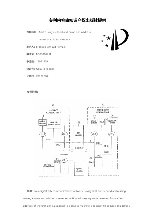
专利名称:Addressing method and name and addressserver in a digital network发明人:François-Arnaud Remael申请号:US09868731申请日:19991224公开号:US07181535B1公开日:20070220专利内容由知识产权出版社提供专利附图:摘要:In a digital telecommunications network having first and second addressing zones, a name and address server in the first addressing zone receiving from a firstaddress of the first zone, assigned to a source machine, a request to provide an addressin relation to the name of a destination machine situated in the second addressing zone, sends to a second address of the first zone a first packet containing at least the said name of destination machine, said second address of the first zone being associated in a static manner to a first address of the second zone, assigned to a management unit. The management unit sends to an interface a second packet destined for the name and address server comprising as origin address, a second address of the second zone assigned to the destination machine. The interface transmits the second packet to the name and address server while replacing the origin address by a third address of the first zone, forming part of a list of addresses of the first zone, forming part of a list of addresses of the first zone allotted to the second addressing zone and associated in a dynamic manner with the second address of the second zone. The name and address server includes this third address in a response to the address provision request returned to the first address of the first zone.申请人:François-Arnaud Remael地址:Pleumeur Bodou FR国籍:FR代理机构:Drinker Biddle & Reath LLP更多信息请下载全文后查看。
埃迪恒睿通型号35SST流量纤维轨道终端机器人说明书

F A N P O W E R E D T E R M I N A L U N I T SC72FAN POWERED TERMINAL UNITS • 35SST SERIESPerformance Data • NC Level Application GuideModel Series 35SST Stealth ™ • Series Flow Fiberglass Liner2. Dash (-) in space indicates a NC less than 20.1-17-22FAN POWERED TERMINAL UNITSCFAN POWERED TERMINAL UNITS • 35SST SERIESPerformance Data • Discharge Sound Power LevelsModel Series 35SST Stealth ™ • Series Flow Fiberglass LinerFAN POWERED TERMINAL UNITSCC75FAN POWERED TERMINAL UNITS • 35SST SERIES∑Motor = ECM.* Primary air valve is closed and therefore primary cfm is zero.Performance Data • AHRI Certification and Performance NotesModel Series 35SST Stealth ™ • Series Flow • AHRI Certification Rating PointsFiberglass LinerRatings are certified in accordance with AHRI Standards.Performance Notes for Sound Power Levels:1. Discharge (external) static pressure is 0.25" w.g. (63 Pa) in all cases, which is the difference (∆Ps) in static pressure from terminal discharge to the room.Discharge Sound Power Levels (SWL) now include duct end reflection energy as part of the standard rating. Including the duct end correction provides sound power levels that would normally be transmitted into an acoustically, non-reflective duct. The effect of including the energy correction to the discharge SWL, is higher sound power levels when compared to previous AHRI certified data. For more information on duct end reflection calculations see AHRI Standard 880.2. Radiated sound power is the breakout noise transmitted through the unit casing walls.3. Sound power levels are in decibels, dB re 10-12 watts.4. All sound data listed by octave bands is raw data without any corrections for room absorption or duct attenuation. Dash (-) in space indicates sound power level is less than 20 dB or equal to background.5. Min. inlet ∆Ps is the minimum operating pressure of the primary air valve section.6. Asterisk (*) in space indicates that the minimum inlet static pressure requirement is greater than 0.5" w.g. (125 Pa) at rated airflow.7. Data derived from independent tests conducted in accordance with ANSI / ASHRAE Standard 130 and AHRIStandard 880.F A N P O W E R E D T E R M I N A L U N I T SFAN POWERED TERMINAL UNITS • 35SST SERIESPerformance Data • Radiated Sound Power LevelsModel Series 35SST Stealth ™ • Series Flow Fiberglass LinerFAN POWERED TERMINAL UNITSCC75FAN POWERED TERMINAL UNITS • 35SST SERIES∑Motor = ECM.* Primary air valve is closed and therefore primary cfm is zero.Performance Data • AHRI Certification and Performance NotesModel Series 35SST Stealth ™ • Series Flow • AHRI Certification Rating PointsFiberglass LinerRatings are certified in accordance with AHRI Standards.Performance Notes for Sound Power Levels:1. Discharge (external) static pressure is 0.25" w.g. (63 Pa) in all cases, which is the difference (∆Ps) in static pressure from terminal discharge to the room.Discharge Sound Power Levels (SWL) now include duct end reflection energy as part of the standard rating. Including the duct end correction provides sound power levels that would normally be transmitted into an acoustically, non-reflective duct. The effect of including the energy correction to the discharge SWL, is higher sound power levels when compared to previous AHRI certified data. For more information on duct end reflection calculations see AHRI Standard 880.2. Radiated sound power is the breakout noise transmitted through the unit casing walls.3. Sound power levels are in decibels, dB re 10-12 watts.4. All sound data listed by octave bands is raw data without any corrections for room absorption or duct attenuation. Dash (-) in space indicates sound power level is less than 20 dB or equal to background.5. Min. inlet ∆Ps is the minimum operating pressure of the primary air valve section.6. Asterisk (*) in space indicates that the minimum inlet static pressure requirement is greater than 0.5" w.g. (125 Pa) at rated airflow.7. Data derived from independent tests conducted in accordance with ANSI / ASHRAE Standard 130 and AHRIStandard 880.FAN POWERED TERMINAL UNITSCC75FAN POWERED TERMINAL UNITS • 35SST SERIES∑Motor = ECM.* Primary air valve is closed and therefore primary cfm is zero.Performance Data • AHRI Certification and Performance NotesModel Series 35SST Stealth ™ • Series Flow • AHRI Certification Rating PointsFiberglass LinerRatings are certified in accordance with AHRI Standards.Performance Notes for Sound Power Levels:1. Discharge (external) static pressure is 0.25" w.g. (63 Pa) in all cases, which is the difference (∆Ps) in static pressure from terminal discharge to the room.Discharge Sound Power Levels (SWL) now include duct end reflection energy as part of the standard rating. Including the duct end correction provides sound power levels that would normally be transmitted into an acoustically, non-reflective duct. The effect of including the energy correction to the discharge SWL, is higher sound power levels when compared to previous AHRI certified data. For more information on duct end reflection calculations see AHRI Standard 880.2. Radiated sound power is the breakout noise transmitted through the unit casing walls.3. Sound power levels are in decibels, dB re 10-12 watts.4. All sound data listed by octave bands is raw data without any corrections for room absorption or duct attenuation. Dash (-) in space indicates sound power level is less than 20 dB or equal to background.5. Min. inlet ∆Ps is the minimum operating pressure of the primary air valve section.6. Asterisk (*) in space indicates that the minimum inlet static pressure requirement is greater than 0.5" w.g. (125 Pa) at rated airflow.7. Data derived from independent tests conducted in accordance with ANSI / ASHRAE Standard 130 and AHRIStandard 880.。
machineLanguage
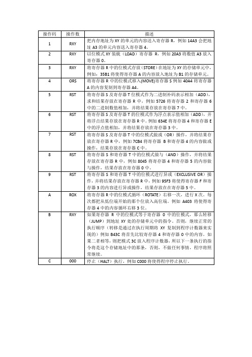
RST
将寄存器S和寄存器T中的位模式进行异或(EXCLUSIVE OR)操作,并将结果存放在寄存器R中,例如95F3将使得寄存器F和寄存器3的内容进行异或操作,结果存放在在寄存器5中。
A
ROX
将寄存器R中的位模式循环(ROTATE)右移一次,进行X次。每次都把从低位端开始的那个位放入高位端。例如A403将使得寄存器4中的内容循环右移3位。
4
ORS
将寄存器R中的位模式移入(MOVE)寄存器S例如40A4将寄存器A的内容复制到寄存器A4。
5
RST
将寄存器S及寄存器T位模式作为二进制补码表示相加(ADD),求和结果存放在寄存器R中,例如5726将寄存器2和寄存器6中的二进制数值相加,并将结果存放在寄存器7中。
6
RST
将寄存器S及寄存器T的位模式作为浮点表示值相加(ADD),并将浮点结果存放在寄存器R中。例如634E将寄存器4和寄存器E中的浮点值相加,并将结果存放在寄存器3中。
操作码
操作数
பைடு நூலகம்描述
1
RXY
把内存地址为XY的单元的内容送入寄存器R,例如14A3会把地址A3的单元内容送入寄存器4。
2
RXY
以位模式XY装载(LOAD)寄存器R,例如20A3将数值A3放入寄存器0。
3
RXY
将寄存器R中的位模式存放(STORE)在地址为XY的存储单元中,例如:35B1将使得寄存器A的内容放入地址为B1的存储单元。
7
RST
将寄存器S及寄存器T中的位模式做或(OR)操作,并将结果存放在寄存器R中,例如7CB4将寄存器B和寄存器4的内容做或操作,结果存放在寄存器C中。
8
RST
将寄存器S和寄存器T中的位模式做与(AND)操作,并将结果存放在寄存器R中,例如8045将寄存器4和寄存器5的内容做与操作,结果存放在寄存器0中。
纯化水微生物限度检查法验证方案
纯化水微生物限度检查法验证方案1. 验证目的:纯化水微生物限度试验采用薄膜过滤法检查。
确认该方法适合于纯化水细菌、霉菌及酵母菌数测定。
2.职责2.1验证委员会:负责验证方案及报告的批准并组织协调验证工作并签发验证证书。
2.2.验证组长2.2.1.负责验证方案的起草2.2.2.负责验证的协调工作,以保证本验证方案的顺利实施。
2.2.3.负责验证报告的审批。
2.2.4.负责发放验证证书。
2.2.5.负责再验证周期的确认。
2.3. 质保部2.3.1.负责验证方案审核2.3.2.负责取样及对样品的检验2.3.3.负责收集验证记录,并加以分析后,起草验证报告。
2.3.4.负责验证数据及结果的审核3. 参照标准:2005版中国药典二部附录XI J微生物限度检查法。
4. 验证项目:细菌、霉菌及酵母菌计数方法的验证。
5. 合格标准:试验组的菌回收率和稀释剂对照组的菌回收率均不得低于70%。
6. 试验材料:6.1. 被验证产品:品名纯化水取样点总出水口洗瓶用水洗涤消毒检验量 5ml6.2. 仪器设备:6.2.1. SYQ/ZDX-35B1型自动座式压力蒸汽灭菌器6.2.2. YOKO-ZX紫外分析暗箱6.2.3. SW-EJ-2FB双人净化工作台6.2.4. 101-2A电热鼓风干燥箱6.2.5.SPX-250B型生化培养箱 (23~28℃)6.2.6.PHW-200S恒温培养箱(35~37℃)6.2.7.CR-50×50×65数显隔水式恒温培养箱(30~35℃) 6.3. 稀释剂: 0.9%无菌氯化钠溶液6.4. 验证用培养基6.5. 验证用菌株:(第3代)7. 菌液制备7.1. 取经35~36℃培养18~24小时的大肠埃希菌、金黄色葡萄球菌、与枯草芽孢杆菌营养肉汤新鲜培养物1ml加入到9ml0.9%无菌氯化钠溶液中,10倍稀释至10-6~10-7约为50~100cfu∕ml的菌悬液备用。
7.2.取经24~25℃培养24~48小时的白色念珠菌改良马丁液体培养物1ml加入到9ml0.9%无菌氯化钠溶液中,10倍稀释至10-5约为50~100cfu∕ml的菌悬液备用。
NXP mcu

TinyM0核心板电路为LPC111x芯片的最小系统,硬件支持2.54mm间距的 标准排针。用户可以将TinyM0核心板配套自行设计的底板进行产品开发。 ● 支持多款芯片
和16位竞争产品的2至4倍。
Cortex-M0内核
● 32位ARM RISC处理器,16位Thumb指令集; ● 功耗与面积高度优化,设计专用于低成本、低功耗场合; ● 24位SysTick定时器; ● 32位硬件乘法器; ● 中断现场自动保存,有处理决定性、固定延迟的中断能力; ● 系统接口支持小端或字节不变的大端数据访问; ● SWD串行线调试。
LPC1300选型表:
器件型号 LPC1343 LPC1342 LPC1313 LPC1311
Flash (KB) 32 16 32 8
SRAM(KB) 8 4 8 2
USB 2.0 Device Device
-
I2C(Fast+) 1 1 1 1
ADC 8ch/10bit 8ch/10bit 8ch/10bit 8ch/10bit
置的新型开漏工作模式
LPC1100
◎ 四个通用计数器/计数器 ◎ 可编程的看门狗定时器(WDT),带锁死功能 ◎ 系统计时器 ◎ 各外设自带时钟分频器,有利于降低功耗
芯片特色:
Cortex-M0处理器性能 ● Cortex-M0微控制器可以轻松超越高端8位和16位器件的
性能水平; ● 内核额定性能为0.9DMIPS/MHz,相当于与其最接近的8位
FREDFET Power MOS 7 低损耗高电压N型增强模电源MOSFET数据手册说明书

050-7040 R e v D 4-2006MAXIMUM RATINGSAll Ratings: TC = 25°C unless otherwise specified.APT10078BFLL APT10078SFLL1000V14A0.780ΩPower MOS 7®is a new generation of low loss, high voltage, N-Channel enhancement mode power MOSFETS. Both conduction and switchinglosses are addressed with Power MOS 7®by significantly lowering R DS(ON)and Qg . Power MOS 7®combines lower conduction and switching losses along with exceptionally fast switching speeds inherent with APT's patented metal gate structure.Characteristic / Test ConditionsDrain-Source Breakdown Voltage (V GS = 0V, I D = 250µA)Drain-Source On-State Resistance 2 (V GS = 10V, I D = 7A)Zero Gate Voltage Drain Current (V DS = 1000V, V GS = 0V)Zero Gate Voltage Drain Current (V DS = 800V, V GS = 0V, T C = 125°C)Gate-Source Leakage Current (V GS = ±30V, V DS = 0V)Gate Threshold Voltage (V DS = V GS , I D = 1mA)Symbol V DSS I D I DM V GS V GSM P D T J ,T STG T L I AR E AR E ASParameterDrain-Source VoltageContinuous Drain Current @ T C= 25°C Pulsed Drain Current1Gate-Source Voltage Continuous Gate-Source Voltage Transient Total Power Dissipation @ T C = 25°C Linear Derating FactorOperating and Storage Junction Temperature Range Lead Temperature: 0.063" from Case for 10 Sec.Avalanche Current 1 (Repetitive and Non-Repetitive)Repetitive Avalanche Energy 1Single Pulse Avalanche Energy4UNIT Volts AmpsVolts Watts W/°C °C Amps mJSTATIC ELECTRICAL CHARACTERISTICSSymbol BV DSS R DS(on)I DSS I GSS V GS(th)UNIT VoltsOhms µA nA VoltsMINTYPMAX10000.7802501000±10035APT10078BFLL_SFLL10001456±30±404033.23-55 to 15030014301300CAUTION: These Devices are Sensitive to Electrostatic Discharge. Proper Handling Procedures Should Be Followed.APT Website - •Lower Input Capacitance •Increased Power Dissipation •Lower Miller Capacitance •Easier To Drive•Lower Gate Charge, Qg3050-7040 R e v D 4-2006DYNAMIC CHARACTERISTICSAPT10078BFLL_SFLLSOURCE-DRAIN DIODE RATINGS AND CHARACTERISTICSTHERMAL CHARACTERISTICSCharacteristic / Test Conditions Continuous Source Current (Body Diode)Pulsed Source Current 1 (Body Diode)Diode Forward Voltage 2 (V GS = 0V, I S = I D -14A)Peak Diode Recovery dv /dt 5Reverse Recovery Time (I S = I D -14A, di /dt = 100A/µs)Reverse Recovery Charge (I S = I D -14A, di /dt = 100A/µs)Peak Recovery Current (I S = I D -14A, di /dt = 100A/µs)Symbol I S I SM V SDdv /dtt rr Q rr I RRMUNIT Amps Volts V/ns ns µC AmpsMINTYPMAX14561.318T j = 25°C 210T j = 125°C 710T j = 25°C 1.0T j = 125°C 3.6T j = 25°C 9.8T j = 125°C14Symbol R θJC R θJAMINTYPMAX0.3140UNIT °C/WCharacteristic Junction to Case Junction to AmbientSymbol C iss C oss C rss Q g Q gs Q gd t d(on)t r td(off)t f E on E off E on E off Characteristic Input Capacitance Output CapacitanceReverse Transfer Capacitance Total Gate Charge 3Gate-Source Charge Gate-Drain ("Miller") Charge Turn-on Delay Time Rise TimeTurn-off Delay Time Fall TimeTurn-on Switching Energy 6Turn-off Switching Energy Turn-on Switching Energy 6Turn-off Switching Energy Test ConditionsV GS = 0VV DS = 25V f = 1 MHz V GS = 10VV DD = 500VI D = 14A @ 25°C RESISTIVE SWITCHINGV GS = 15VV DD = 500V I D = 14A @ 25°CR G = 1.6ΩINDUCTIVE SWITCHING @ 25°CV DD = 667V V GS = 15V I D = 14A, R G = 3ΩINDUCTIVE SWITCHING @ 125°CV DD = 667V V GS = 15V I D = 14A, R G = 3ΩMIN TYP MAX 252543075951260983093557574095UNIT pFnCnsµJ1Repetitive Rating: Pulse width limited by maximum junction temperature2Pulse Test: Pulse width < 380 µs, Duty Cycle < 2%3See MIL-STD-750 Method 34714Starting T j = +25°C, L = 13.27mH, R G = 25Ω, Peak I L = 14A5dv /dt numbers reflect the limitations of the test circuit rather than the device itself. I S ≤ I D -14A di /dt ≤ 700A/µsV R ≤ 1000T J ≤ 150°C 6 Eon includes diode reverse recovery. See figures 18, 20.APT Reserves the right to change, without notice, the specifications and inforation contained herein.Z θJ C , T H E R M A L I M P E D A N C E (°C /W )RECTANGULAR PULSE DURATION (SECONDS)FIGURE 1, MAXIMUM EFFECTIVE TRANSIENT THERMAL IMPEDANCE, JUNCTION-TO-CASE vs PULSE DURATION0.350.300.250.200.150.100.050050-7040 R e v D 4-2006APT10078BFLL_SFLLTypical Performance CurvesR D S (O N ), D R A I N -T O -S O U R C E O N R E S I S T A N C E I D , D R A I N C U R R E N T (A M P E R E S )I D , D R A I N C U R R E N T (A M P E R E S )(N O R M A L I Z E D )V G S (T H ), T H R E S H O L D V O L T A G E B V D S S , D R A I N -T O -S O U R C E B R E A K D O W N R D S (O N ), D R A I N -T O -S O U R C E O N R E S I S T A N C EI D , D R A I N C U R R E N T (A M P E R E S )(N O R M A L I Z E D )V O L T A G E (N O R M A L I Z E D )V DS , DRAIN-TO-SOURCE VOLTAGE (VOLTS)FIGURE 2, TRANSIENT THERMAL IMPEDANCE MODELFIGURE 3, LOW VOLTAGE OUTPUT CHARACTERISTICS V GS , GATE-TO-SOURCE VOLTAGE (VOLTS)I D , DRAIN CURRENT (AMPERES)FIGURE 4, TRANSFER CHARACTERISTICSFIGURE 5, R DS (ON) vs DRAIN CURRENTT C , CASE TEMPERATURE (°C)T J , JUNCTION TEMPERATURE (°C)FIGURE 6, MAXIMUM DRAIN CURRENT vs CASE TEMPERATURE FIGURE 7, BREAKDOWN VOLTAGE vs TEMPERATURE T J , JUNCTION TEMPERATURE (°C)T C , CASE TEMPERATURE (°C)FIGURE 8, ON-RESISTANCE vs. TEMPERATURE FIGURE 9, THRESHOLD VOLTAGE vs TEMPERATURE0.00295F0.0114F0.174FJunction temp. (°C)RC MODELCase temperature. (°050-7040 R e v D 4-2006V DS , DRAIN-TO-SOURCE VOLTAGE (VOLTS)V DS , DRAIN-TO-SOURCE VOLTAGE (VOLTS)FIGURE 10, MAXIMUM SAFE OPERATING AREAFIGURE 11, CAPACITANCE vs DRAIN-TO-SOURCE VOLTAGEQ g , TOTAL GATE CHARGE (nC)V SD , SOURCE-TO-DRAIN VOLTAGE (VOLTS)FIGURE 12, GATE CHARGES vs GATE-TO-SOURCE VOLTAGEFIGURE 13, SOURCE-DRAIN DIODE FORWARD VOLTAGEV G S , G A T E-T O -S O U R C E V O L T A G E (V O L T S )I D, D R A I N C U R R E N T (A M P E R E S )I D R , R E V E R S E D R A I N C U R R E N T(A M P E R E S )C , C A P A C I T A N C E (p F )I D (A)I D (A)FIGURE 14, DELAY TIMES vs CURRENTFIGURE 15, RISE AND FALL TIMES vs CURRENT I D (A)R G , GATE RESISTANCE (Ohms)FIGURE 16, SWITCHING ENERGY vs CURRENTFIGURE 17, SWITCHING ENERGY VS. GATE RESISTANCES W I T C H I N G E N E R G Y (µJ )t d (o n ) a n d t d (o f f ) (n s )S W I T C H I N G E N E R G Y (µJ )t r a n d t f (n s )050-7040 R e v D 4-2006APT10078BFLL_SFLLAPT’s products are covered by one or more of U.S.patents 4,895,810 5,045,903 5,089,434 5,182,234 5,019,5225,262,336 6,503,786 5,256,583 4,748,103 5,283,202 5,231,474 5,434,095 5,528,058 and foreign patents. US and Foreign patents pending. All Rights Reserved.Dimensions in Millimeters and (Inches)TO -247 Package OutlineDimensions in Millimeters (Inches)and Leads are PlatedD 3PAK Package OutlineFigure 18, Turn-on Switching Waveforms and Definitions Figure 19, Turn-off Switching Waveforms and DefinitionsI C APT15DF100V CEV DD GSwitching EnergyDrain CurrentDrain VoltageGate VoltageT J125°C 10%0t d(off)90%t f90%Drain CurrentDrain VoltageGate VoltageT J 125°CSwitching Energy10%t d(on)90%5%t r5%10%。
广工计算机科学概论试卷B
二、 判断题(每题 2 分,共 10 分)
1、在计算机内部保存浮点数时,尾数部分采用定点整数形式 2、指令寄存器(IR)用于存储 CPU 下一条待执行指令的地址 3、文件系统中的源程序文件是有结构的记录式文件 4、在分时系统中,时间片一定,用户数越少,响应时间越长 5、计算机网络是计算机技术与通信技术紧密结合的产物
广东工业大学考试试卷 ( B )
座位号:
课程名称: 考试时间:
题 号 一
计算机系统导论 年
二 三
试卷满分 100 分 日 (第
六
月
四
周 星期
七 八
ห้องสมุดไป่ตู้
)
九 十 总分
五
评卷得分 评卷签名 复核得分 复核签名
线
考试地点:
一、 单项选择题(每题 2 分,共 20 分)
1、十进制 0.25 对应的二进制是( A、.001 B、.010 ) D、.011
B
RXY
C
000
主存储器的内容如下图所示:
(1)请将地址为 A0-A9 单元中的指令翻译成自然语言。 (2)如果机器在程序计数器的值为 00 时启动,那么机器停止时主存储器单元 A、B、C 的值各 为多少? 五、论述题(10 分) 结合自身体会,阐述学习《计算机系统导论》对自己有何帮助以及在大学四年的学习规划。
4、下列关于 CISC 的叙述,错误的是: ( A、CISC 指复杂指令集的计算机 C、ARM 处理器是 CISC 处理器
装
B、CISC 计算机支持数量众多的复杂指令 D、Intel x86 处理器属于 CISC 处理器 ) 。
5、进程和程序的本质区别是( A.前者为动态的,后者为静态的
B.前者存储在内存,后者存储在外存 C.前者在一个文件中,后者在多个文件中
罗弗公司2010年版低功耗高电压负压电子传输器2SB1182和2SB1240产品说明书
Medium power transistor (-32V, -2A)2SB1182 / 2SB1240●Features1) Low V CE(sat).V CE(sat) = -0.5V (Typ.) (I C /I B = -2A / -0.2A)2) Complements 2SD1758 / 2SD1862.●StructureEpitaxial planar type PNP silicon transistor●Absolute maximum ratings (Ta=25︒C)∗1 Single pulse, Pw =100ms∗2 Printed circuit board, 1.7mm thick, collector copper plating 100mm 2or larger.ParameterV CBO V CEO V EBO P C Tj Tstg−40V V V A(DC)W (Tc =25°C )W°C °C−32−5−2I CA (Pulse)−3101∗1∗22SB11822SB1240150−55 to 150Symbol Limits Unit Collector-base voltage Collector-emitter voltage Emitter-base voltage Collector currentCollector power dissipationJunction temperature Storage temperature●Electrical characteristics (Ta=25︒C)∗ Measured using pulse current.ParameterSymbol BV CBO BV CEO BV EBO I CBO I EBO h FE V CE(sat)f T CobMin.−40−32−5−−120−−−−−−−−10050−−−−1−1390−0.8∗∗−−V I C = −50μA I C = −1mA I E = −50μA V CB = −20V V EB = −4V I C /I B = −2A/ −0.2A V CE = −5V, I E =0.5A, f =100MHz V CB = −10V, I E =0A, f =1MHzV VμA μA −−V CE = −3V, I C = −0.5AV MHz pFTyp.Max.Unit Conditions−0.5Collector-base breakdown voltage Collector-emitter breakdown voltage Emitter-base breakdown voltage Collector cutoff current Emitter cutoff currentCollector-emitter saturation voltage DC current transfer ratio Transition frequency Output capacitance●Packaging specifications and h FEPackage CodeBasic ordering unit (pieces)TapingTL 2500h FE QR 2SB1182−TV22500−QR2SB1240Typeh FE values are classified as follows :Item h FEQ 120 to 270R 180 to 390●Electrical characteristic curvesFig.1 Grounded emitter propagationcharacteristicsBASE TO EMITTER VOLTAGE : V BE (V)C O L L E C T O R C U R R E N T : I C (m A )−−−−−−−−−−Fig.2 Grounded emitter outputcharacteristics−−−−−C O L LE C T O R C U R R E N T : I C (A )COLLECTOR TO EMITTER VOLTAGE : V CE (V)Fig.3 DC current gain vs.collector curren ( )D C C U R RE N T G A I N : hF ECOLLECTOR CURRENT : I C (mA)Fig.4 DC current gain vs.collector current ( )D C C U R RE N T G A I N : hF ECOLLECTOR CURRENT : I C (mA)Fig.5 Collector-emitter saturationvoltage vs. collector current ( )C O L L E C T O R S A T U R A T I O N V O L T A G E : V C E (s a t ) (m V )−−−−Fig.6 Collector-emitter saturationvoltage vs. collector current ( )−−−−−C O L L E C T O R S A T U R A T I O N V O L T A G E : V C E (s a t ) (m V )COLLECTOR CURRENT : I C (mA)Fig.7 Base-emitter saturation voltagevs. collector currentCOLLETOR CURRENT : I C (mA)B A S E S A T U R A T I O N V O L T A G E : V B E (s a t )(V )−−−−−Fig.8 Gain bandwidth product vs.emitter currentEMITTER CURRENT : I E (mA)T R A N S I T I O N F R E Q U E N C Y : f T (M H z )Fig.9 Collector output capacitance vs.collector-base voltageEmitter input capacitance vs. emitter-base voltageCOLLECTOR TO BASE VOLTAGE : V CB (V)EMITTER TO BASE VOLTAGE : V EB (V)C O L L E C T O R O U T P U T C A P AC I T A N C E : C o b (p F )E M I T T E R I N P U T C A P A C I T A N C E : C i b (p F )Fig.10 Safe operation area(2SB1182)−−−−−−−−−−C O L L E C T O R C U R R E N T : I C (A )COLLECTOR TO EMITTER VOLTAGE : V CE (V)NoticeN o t e sNo copying or reprod uction of this d ocument, in part or in whole, is permitted without theconsent of ROHM Co.,Ltd.The content specified herein is subject to change for improvement without notice.The content specified herein is for the purpose of introd ucing ROHM's prod ucts (hereinafter"Products"). If you wish to use any such Product, please be sure to refer to the specifications,which can be obtained from ROHM upon request.Examples of application circuits, circuit constants and any other information contained hereinillustrate the standard usage and operations of the Products. The peripheral conditions mustbe taken into account when designing circuits for mass production.Great care was taken in ensuring the accuracy of the information specified in this document.However, should you incur any d amage arising from any inaccuracy or misprint of suchinformation, ROHM shall bear no responsibility for such damage.The technical information specified herein is intended only to show the typical functions of andexamples of application circuits for the Prod ucts. ROHM d oes not grant you, explicitly orimplicitly, any license to use or exercise intellectual property or other rights held by ROHM andother parties. ROHM shall bear no responsibility whatsoever for any dispute arising from theuse of such technical information.The Products specified in this document are intended to be used with general-use electronicequipment or devices (such as audio visual equipment, office-automation equipment, commu-nication devices, electronic appliances and amusement devices).The Products specified in this document are not designed to be radiation tolerant.While ROHM always makes efforts to enhance the quality and reliability of its Prod ucts, aProduct may fail or malfunction for a variety of reasons.Please be sure to implement in your equipment using the Products safety measures to guardagainst the possibility of physical injury, fire or any other damage caused in the event of thefailure of any Product, such as derating, redundancy, fire control and fail-safe designs. ROHMshall bear no responsibility whatsoever for your use of any Product outside of the prescribedscope or not in accordance with the instruction manual.The Prod ucts are not d esigned or manufactured to be used with any equipment, d evice orsystem which requires an extremely high level of reliability the failure or malfunction of whichmay result in a direct threat to human life or create a risk of human injury (such as a medicalinstrument, transportation equipment, aerospace machinery, nuclear-reactor controller, fuel-controller or other safety device). ROHM shall bear no responsibility in any way for use of anyof the Prod ucts for the above special purposes. If a Prod uct is intend ed to be used for anysuch special purpose, please contact a ROHM sales representative before purchasing.If you intend to export or ship overseas any Product or technology specified herein that maybe controlled under the Foreign Exchange and the Foreign Trade Law, you will be required toobtain a license or permit under the Law.Thank you for your accessing to ROHM product informations.More detail product informations and catalogs are available, please contact us.ROHM Customer Support System/contact/。
XB6 系列_ EtherNet IP_插片式 I O 用户手册说明书
2.1
命名规则 .......................................................................................................................................................... 3
EtherNet/IP XB6 系列插片式 I/O 用户手册
南京实点电子科技有限公司
版权所有 © 南京实点电子科技有限公司 2023。保留一切权利。 非经本公司书面许可,任何单位和个人不得擅自摘抄、复制本文档内容的部分或全部,并不得以任何形式传播。 商标声明
和其它实点商标均为南京实点电子科技有限公司的商标。 本文档提及的其它所有商标或注册商标,由各自的所有人拥有。 注意 您购买的产品、服务或特性等应受实点公司商业合同和条款的约束,本文档中描述的全部或部分产品、服务或特性可 能不在您的购买或使用范围之内。除非合同另有约定,实点公司对本文档内容不做任何明示或默示的声明或保证。 由于产品版本升级或其他原因,本文档内容会不定期进行更新。除非另有约定,本文档仅作为使用指导,本文档中的 所有陈述、信息和建议不构成任何明示或暗示的担保。
3.3
接口参数 .......................................................................................................................................................... 8
5.2
安装拆卸步骤 .............................................................................................................................................. 19
魏德米勒电源产品选型
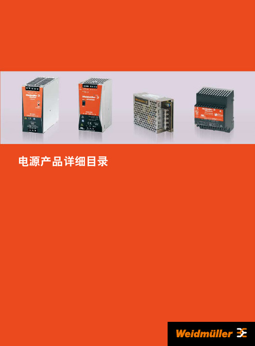
符合EN60204 符合EN61558-2-17 符合EN50178/ VDE0160 SELV符合EN60950, PLEV符合EN60204 VDE0100-410/ 符合DIN57100-410 符合VDE0106-101
技术数据总览
型号
额定输入电压 输入电压范围 输入电流(最大/最小) 建议后备熔丝
IE-LINE 以太网联接组件
JACKPAC® IP68
有源SAI分配器
电子外壳
模拟信号隔离器 光电耦合器
继电器
接线端子
接口产品
测量控制设备 电涌保护
Fieldbus总线接口
无源SAI分配器及电缆
信号
电缆接头
接线盒及附件
螺柱接线端子
能源
电气柜
电源分配器 FieldPower®
重载接插件
Modicon Quantum 32 O 型号 140DDO35300 产品数据表说明书

D i s c l a im er : T h i s d o c u m e n t a t i o n i s n o t i n t e n d e d a s a s u b s t i t u t e f o r a n d i s n o t t o b e u s e d f o r d e t e r m i n i n g s u i t a b i l i t y o r r e l i a b i l i t y o f t h e s e p r o d u c t s f o r s p e c i f i c u s e r a p p l i c a t i o n sProduct data sheetCharacteristics140DDO35300discrete output module Modicon Quantum - 32 O solid stateMainRange of productModicon Quantum automation platform Product or component type Dc discrete output module Discrete output number32ComplementaryGroup of channels 4 groups of 8Discrete output logic Positive logic (source)Addressing requirement 2 output words Discrete output voltage 24 V DC Output voltage limits 19.2...30 VAbsolute maximum output 56 V for 1.3 s decaying pulse Voltage drop0.4 V 0.5 A Maximum load current16 A per module 16 A per module 4 A per group 4 A per group Surge current <= 5 A for 0.0005 s Response time <= 1 ms at state 0 to state 1<= 1 ms at state 1 to state 0Leakage current 0.4 mA 30 VLoad inductance Inductance(H) = 0.5/((current(A))² x (switching frequency(Hz))) 50 Hz Fault indication Blown fuseLoss of field power Associated fuse rating3 A each point 3 A each point 5 A per group 5 A per groupIsolation between channels and bus 1780 Vrms DC for 1 minute Isolation between group 500 Vrms DC for 1 minuteProtection typeInternal output protection by 5 A fuse per groupPower dissipation 1.75 W + (0.4 V x total module load current)Marking CELocal signalling1 LED green bus communication is present (Active)1 LED red external fault detected (F)32 LEDs green input status Bus current requirement 330 mA 330 mA Module format Standard Product weight0.45 kgEnvironmentProduct certificationsABS BV C-Tick DNVFM Class 1 Division 2GL GOST RINA RMRSSafety certification non interfering StandardsCSA C22.2 No 142UL 508Resistance to electrostatic discharge 4 kV contact conforming to IEC 801-28 kV on air conforming to IEC 801-2Resistance to electromagnetic fields 10 V/m 80...2000 MHz conforming to IEC 801-3Ambient air temperature for operation 0...60 °C Ambient air temperature for storage -40...85 °CRelative humidity 95 % without condensation Operating altitude<= 5000 mOffer SustainabilitySustainable offer status Green Premium productRoHS (date code: YYWW)Compliant - since 0848 - Schneider Electric declaration of conformity Schneider Electric declaration of conformity REAChReference not containing SVHC above the threshold Reference not containing SVHC above the threshold Product environmental profileAvailableProduct environmental Product end of life instructionsAvailableEnd of life manualContractual warrantyWarranty period18 monthsDimensions DrawingsRacks for Modules MountingDimensions of Modules and Racks(1) 2 slots (2) 3 slots (3) 4 slots (4) 6 slots (5)10 slots (6)16 slotsConnections and Schema24 Vdc Discrete Output Source Module Wiring Diagram。
华邦(winbond)产品手册
PRODUCT GUIDE ==Winbond、ISSI 授权香港及中国代理== 8 位单片宽工作电压系列
型号 ROM 型式 ROM RAM I/O 脚 外扩存储 器空间 64K 工作电压 定时器/ 计数器 3 封装 Int 特殊功能 PDIP 6 CMOS 通用功能 特殊 I/O 口 /INT2, /INT3,WDT 特殊 I/O 口 /INT2, /INT3,WDT 16 KB 掩膜 ROM W78L54 掩膜 16K 256 32/36 64K 5.5V - 1.8V 3 8 特殊 I/O 口 /INT2,/INT3,WDT W78L801 掩膜 4K 256 36 64K 5.5V - 1.8V 2 12 特殊 I/O 口,P1 口 退出省电方式 WDT 可多次编程,特殊 I/O 口 / INT2, /INT3, WDT 可多次编程特殊 I/O 口 / INT2, /INT3, WDT 可多次编程特殊 I/O 口 / INT2, /INT3, WDT 可多次编程,可在线编程 特殊 I/O 口/ INT2, /INT3 可多次编程,可在线编程 W78LE516 Flash EPROM 64K 512 32/36 64K 5.5V - 2.4V 3 8 特殊 I/O 口,/ INT2, /INT3, 可多次编程,可在线编程 W78LE365 Flash EPROM 64K 1280 32/36 64 K 5.5V - 2.4V 3 8 特殊 I/O 口/ INT2, /INT3,WTD,PWM 特殊 I/O 口 W78LE812 Flash EPROM 8K 256 36 64K 5.5V - 2.4V 3 14 P1 口退出省电方式 WDT,UART 40 44 44 40 44 44 40 44 44 40 44 44 40 44 44 40 PLCC 44 PQFP 44
F-35 Lightning Flight Controller User Manual
F-35 LIGHTNINGFLIGHT CONTROLLERUSER MANUAL VERSION 1.5ContentsManual user log (3)Introduction (4)Features (4)Pinouts (5)Dimensions (5)Connections (6)Connection with ESCs and Servos: (6)1.Flying Wing: (6)2.Airplane: (6)Connection With Receivers: (9)I.TBS Receiver (9)1. TBS Crossfire Micro Rx V2 (Plug and play with Micro Rx Cable) (9)2. TBS Crossfire Micro Rx V2 (Plug and Play with Micro Rx and TBS-Ext Cable forWireless Connection) (9)3. TBS Crossfire Diversity Rx Only Use CRSF Protocol (10)4. TBS Crossfire Diversity Rx Use PPM + Serial TX-RX (11)II.FrSky Receiver (12)1.XSR (Plug and Play with F-RX Cable) (12)2.R-XSR (12)3.R9 (13)4.R9 Slim (13)5.L9R (14)6.SPD15 (14)7.XM+ (15)III.Futaba Receiver (15)IV.DJI Ocussync Air Unit (16)V.Spektrum Receiver (16)VI.Dragon Link Micro UHF Receiver (17)Connection with VTX: (19)1. Using with Stealth Long Range VTX (Plug and Play with VTX Cable) (19)ing with Tramp HV (20)ing with TBS Unify Pro 5G8 HV: (20)ing with TBS Unify 2G4: (21)Connection with Furious AirSpeed Sensor (21)Connection with Furious FPV GPS Module (Plug and Play with GPS Cable) (22)Connection with RadioLink M8N GPS (23)Connection with Camera (Plug and Play with CAM Cable) (24)1. RunCam Eagle 2 (24)2. RunCam Swift 2 (24)3. RunCam Split 2 (25)4. Foxeer Arrow Mini (25)How To Set Up Wing With INAV Configurator (26)How To Calibrate Sensor (27)How To Connect INAV Wireless To F-35 Via TBS Crossfire TX (29)How To Connect Smartphone To F-35 Lightning FC Via FuriousFPV Bluetooth Module (31)How To Setup Failsafe (33)How To Use NAV LAUNCH (Auto Take Off) Function (34)INAV MODE (35)How to assembly silicone for airspeed sensor (36)Video Guide (36)Frequently Asked Questions (37)Manual user logV1.5:Update configure with DJI OcuSync Air Unit*Please note: In this manual, BLUE Texts have hyperlinks to check out guideline.IntroductionFurious FPV F-35 Lightning FC - Elevate Your Horizons.Step into the all new F-35 Lightning FC - Furious FPV's 1st dedicated wing flight controller, ready and waiting to open all new worlds to winged FPV.Encompassed by a robust aluminum case for maximum levels of protection and strength, the F-35 FC offers the ultimate levels of FPV capability that is dedicated & purpose built for the demands and capabilities of FPV winged flight.Ultra easy to install with a massively powerful MCU STM F4 micro controller, the F-35 Lightning FC supports a full (6) UART's for GPS, VTX Control, S.PORT Telemetry, Crossfire RX, RX, Bluetooth functionality. With these systems in play, the F-35 offers worlds of capability & performance for maximum levels of FPV flight.Integrating a built in 5V@3A BEC, buzzer port, anti-vibration silicone dampeners and battery monitor with current sensor, the F-35 Lightning FC packs a massive punch in an ultra-compact form. Pair this with a built in Barometer & OSD system, the F-35 FC is the game changing flight controller that is ready for anything and everything a pilot could possibly desire.Take your winged FPV flight to new worlds and beyond with the Furious FPV F-35 Lightning FC - the ultimate winged FPV flight control system.Features∙Flight Controller 6DOF + 3DOF MAG∙MCU STM F4 high performance∙Built-in OSD∙Support up to 6 UARTs (GPS, VTX Control, S.PORT Telemetry,Crossfire RX, RX, Bluetooth)∙Built-in Driver Inverter for SBUS and S.PORT connections∙Built-in Battery Voltage and Current monitor∙Camera and VTX port built-in Peripheral pass∙Built-in 5V@3A BEC for small Digital servos, can be easily changed to External BEC for bigger Servos∙Built-in Buzzer port∙High quality silicone wires with optimized lengths are included∙Support INAV firmware∙Vertical USB and ports => easy to install∙Pro version has GPS module, AirSpeed Sensor, Buzzer and Bluetooth Module∙Weight: 34g∙Voltage Range: 2S-6S LiPoPinoutsDimensionsConnectionsConnection with ESCs and Servos: 1.Flying Wing:-Location ESC: 1, 2-Location Servos: 3, 4Ex: Reptile S800 Sky Shadow Flying Wing2.Airplane:-Location ESC: 1, 2-Location Servos: 3, 4, 5, 6Ex1: Volantex RangerEx2: Twin DreamOpen INAV Configurator Go to CLI tab and paste this strings as the picture above. Then, hit Enter:# mixermixer CUSTOMAIRPLANEmmix resetmmix 0 1.000 0.000 0.000 0.300 #Left motormmix 1 1.000 0.000 0.000 -0.300 #Right motor# servo mixsmix resetsmix 0 3 0 100 0 #servo 3 takes Stabilised ROLL (PWM 4)smix 1 4 0 100 0 #servo 4 takes Stabilised ROLL (PWM 5)smix 2 5 2 100 0 #servo 5 takes Stabilised YAW (PWM 6)smix 3 2 1 100 0 #servo 2 takes Stabilised PITCH (PWM 3)saveEx 3: V-TailOpen INAV Configurator Go to CLI tab and paste this strings. Then, hit Ente r: # mixermixer CUSTOMAIRPLANEmmix resetmmix 0 1.0 0.0 0.0 0.0 # motorsmix resetsmix 0 2 0 -100 0 # servo 2 takes Stabilised ROLLsmix 1 3 0 -100 0 # servo 3 takes Stabilised ROLLsmix 2 4 1 100 0 # servo 4 takes Stabilised PITCHsmix 3 5 1 -100 0 # servo 5 takes Stabilised -PITCHsmix 4 4 2 -100 0 # servo 4 takes Stabilised YAWsmix 5 5 2 -100 0 # servo 5 takes Stabilised YAWsmix 6 6 8 -100 0 # servo 6 takes RC AUX 1 (camera yaw)smix 7 7 9 -100 0 # servo 7 takes RC AUX 2 (drop bomb)saveConnection With Receivers:*Warning: Only support power is 5V for receiverI.TBS Receiver1.TBS Crossfire Micro Rx V2 (Plug and play with Micro Rx Cable)2.TBS Crossfire Micro Rx V2 (Plug and Play with Micro Rx and TBS-Ext Cablefor Wireless Connection)Video: Wireless connection to INAV via TBS Crossfire Tx + TBS Micro Rx V23.TBS Crossfire Diversity Rx Only Use CRSF Protocol4.TBS Crossfire Diversity Rx Use PPM + Serial TX-RX*Note:To using PPM, you need to open INAV Configurator Go to Configuration tab and drag to Receiver Mode. Then, select PPM RX input as the picture belowII.FrSky Receiver1.XSR (Plug and Play with F-RX Cable)2.R-XSR4.R9 Slim6.SPD15III.Futaba ReceiverIV.DJI Ocussync Air UnitV.Spektrum ReceiverVI.Dragon Link Micro UHF ReceiverOpen INAV Configurator Go to Configuration tab and drag to Receiver Mode. Then, select like as the picture below*Note:With Dragon Link V2 Rx, please use the Dragon Link GUI software to configure CH7 port from PPM (default) to SBUSDownload software:DragonLink GUIConnection with VTX:ing with Stealth Long Range VTX (Plug and Play with VTX Cable)ing with Tramp HV*Note: If using our VTX Cable, please swap wires the same as pin outs of this VTX ing with TBS Unify Pro 5G8 HV:ing with TBS Unify 2G4:Connection with Furious AirSpeed Sensor Check out How to assembly silicone tube for Airspeed sensorConnection with Furious FPV GPS Module (Plug and Play with GPS Cable)*Warning:For the first time set up and whenever you change your location. You need to leave the Wing or Airplane on the field for approximately 5 minutes so that the GPS is updatedOpen INAV Configurator →Click Configuration tab → Drag to GPS and configure as the picture below:Connection with RadioLink M8N GPSOpen INAV Configurator →Click Configuration tab → Drag to GPS and configure as the picture below:Connection with Camera (Plug and Play with CAM Cable)1.RunCam Eagle 22.RunCam Swift 23.RunCam Split 24.Foxeer Arrow MiniHow To Set Up Wing With INAV ConfiguratorStep1:Calibrate Sensor(Click double to go to How to calibrate Sensor page)INAV requires you to follow the accelerometer calibration steps. These steps are different to Cleanflight & Betaflight. So don't skip reading this section, it's vitally important. But we have wireless so you should do this in the final step.Step2:Set up “Ports” tabIf use TBS Crossfire Micro receiver, you don’t need to change anything. Because we have ready configuredIf use XSR receiver, Please turn on Serial Rx of UART3 to use Receiver Mode Step3:Set up “Configuratios” tabIf use TBS Crossfire Micro receiver,you don’t need to change anything. Because we have ready configuredIf use XSR receiver, drag to Receiver Mode and select SBUS in the Serial Receiver ProviderChange model: There are two models that you can choose: Airplane and Flying WingStep4:Configure “Receiver” tabCheck range and value: Your transmitter should use NO mixing at all (so separate channels for Thr, Ail, Rud, Ele).Check that when moving the sticks, the rightchannels moves in the receiver window. Also, everything should be centered at 1500us, and full stick movement should be 1000-2000us. Use sub trim and travel range on your TX to set this up.Check Channel Map: Please set correctly channel map with the channel on your transmitterStep5:Set up “Servos” tab-If reverse Servo, change "Direction and rate" from +100 to -100-If Servo exceed maximum wanted deflection reduce min/max-If control surfaces are not perfectly centered adjust servo midpoint. (This is after setting them up as close as possible mechanically)*Note:In the Servos tab servos are counted from 0-7 while in the Motors tab they run from 1-8.Step6: Set up Mode(click MODE to check mode’s description table)1.Select Mode tab2.Drag to mode that you want to use. Then, click Add Range and select CHchannel for switch that you want to use this modeStep7:Set FailsafeHow To Calibrate SensorAfter building new an Airplane, you must calibrate Magnetometer and Accelerometer sensor. With F-35 Lightning FC, we don't need to plug USB cable that can use wireless connection with FuriousFPV Bluetooth Module or TBS Crossfire TX. Step 1: Connect F-35 Lightning FC with INAV configuratorStep 2: At Setup tab1.Calibrate Accelerometer: Please click Calibrate Accelerometer to calibrate 6points Accelerometer sensor like the below pictures:pass Calibrate:Please click Calibrate Magnetometer then You have 30seconds to hold the copter in the air and rotate it so that each side (front, back, left, right, top and bottom) points down towards the earth.3.Board Orientation: If you have your board rotated in any way, change boardalignment to match- please check the below pictures:(1) (2)(3) (4)How To Connect INAV Wireless To F-35 Via TBS Crossfire TXThe Device:-TBS Micro RX V2 + TBS Crossfire TX-Micro RX cable for F-35 + TBS-External Cable for F-35 (Include in the package)-App: INAV Configurator on PC, EZ-Gui on Android.-Video: Wireless connection to INAV via TBS Crossfire Tx + TBS Micro Rx V2Step 1: Using TBS-Ext cable plug to Micro RX cable like bellow picture:Step 2: Mapping Output channels for TBS Micro RX.-Output 1: CRSF TX-Output 2: CRSF RX-Output 3: Serial RX-Output 4: Serial TXStep 3: Configure your TBS Crossfire Module.Please select Bluetooth protocol of TBS TX module is BRIDGE.*Note: Verify that you turn on Telemetry on ReceiverStep 4: Connect your device to use Configurator app.Option1: Connect with PC:e Bluetooth on PC search and add your TBS Module Bluetooth. NormallyTBS have name is Crossfire#### (# is number).2.Open INAV Configurator on PC, then check new number using toconnect TBS Crossfire TX and select it. (You can check it in Device Manager).And select Baud rate is 57600.3.Turn on WIRELESS mode of INAV at the Right-Top interface of app. Then, clickConnect button to connect.Now you can do anything with a wireless connection same when you connect with USB cable.Option2: Connect with EZ-Gui on Android app:1.Download and install app at here: DOWNLOAD2.Turn On Bluetooth on your mobile3.Open EZ Gui:Click icon 3 Vertical dots the Top-Right screen and click Settings to go to page setting and configure for Connections. At here, we will selectconnection is Bluetooth then click SELECT BT DEVICE to search you TBSCrossfire module and select it when detected your module.-Click next icon and select Firmware is Cleanflight/Betaflight/INAV.-Click next and select option same as units or another options. After app will come back home screen.4.At Home Screen, please click CONNECTS to connect your app to FC.How To Connect Smartphone To F-35 Lightning FC Via FuriousFPV Bluetooth ModuleThe Device:-FuriousFPV Bluetooth Module-App: INAV Configurator on PC, EZ-Gui on Android.-Video: Calibrate sensor with wireless connection Via Bluetooth moduleStep 1: Plug FuriousFPV module into F-35 Lightning FC. Then, go into Ports tab on the INAV Configurator and configure as the pictures below:Step 2: Connect with EZ-Gui on Android app1.Download and install app at here: DOWNLOAD2.Turn On Bluetooth on your mobile3.Open EZ Gui:Click icon 3 Vertical dots the Top-Right screen and click Settings to go to page setting and configure for Connections. At here, we will selectconnection is Bluetooth then click SELECT BT DEVICE to search you TBS Crossfire module and select it when detected your module.-Click next icon and select Firmware is Cleanflight/Betaflight/INAV.-Click next and select option same as units or another options. After app will come back home screen.4.At Home Screen, please click CONNECT to connect your app to FC. How To Setup FailsafeSetting up Return Home for Failsafe to purpose: when Wing lost signal with Transmitter, Wing will auto return home afterwardStep 1: Configure ReceiverThere are two options to configure:Option 1: Cut off the channelOption 2: Set Position1.Go into Modes tab and select a switch for Failsafe2.Set Switches and Sticks on your transmitter to the following below-Throttle: 0% (No throttle)-Aileron: 50% (No input, Stick center)-Rudder: 50% (No input, Stick center)-Elevator: 50% (No input, Stick center)-Failsafe mode: activated-Arm switch: Disarmed (If you use stick arming you can skip this)Step 2: Configure INAV Configurator1.Open INAV Configurator and go into Failsafe tab2.Enable RTH on the setting stageHow To Use NAV LAUNCH (Auto Take Off) Function Video: How to use NAV LAUNCH (Auto Take off) with F-35 Lightning FCStep1: Open “INAV Configurator”→Select “Mode” tab → drag to NAV LAUNCH function, click Add Range and select CH channel for switch that you want to use this modeStep2: Set switch to NAV LAUNCH mode prior to arming (note that it won't actually enable until arming)Step3: ARM the plane. Motor should start spinning at min_throttle (if MOTOR_STOP is active, motor won't spin)*Note:-NAV LAUNCH is automatically aborted after 5 seconds or by any pilot touch on PITCH/ROLL stick-Verify that motor don't respond to throttle stick motionStep4: Put throttle stick to desired throttle value to be set after launch is finished. Step5: Throw the airplane.*Note:It must be thrown leveled or thrown by slinging it by wingtipStep6: Launch sequence will finish when pilot switch off the NAV LAUNCH mode or move the sticksHow to assembly silicone for airspeed sensorVideo GuideVideo 1: Wireless connection to INAV via TBS Crossfire Tx + TBS Micro Rx V2 Video 2: Calibrate sensor with wireless connection Via Bluetooth module Video 3: How to use NAV LAUNCH (Auto Take off) with F-35 Lightning FC Video 4: How to flash firmware and calibrate AcceloremeterVideo 5: Calibrations sensor and active Compass Calibrate button on INAV 1.9 Video 6: Setup TBS Nano RX and set RSSI to F-35 LightningFrequently Asked QuestionsQ: Why don’t the Hardware Health work?A: In the (P1) picture, the Hardware Health is not working. The reason is that you don’t plug GPS module or don’t power on the FC. To solve this issue, you need to plug GPS module and verify that plugged battery for FC. Then, this function will work afterward as the (P2) picture.(P1)(P2)Q: Cannot Calibrate Acceloremeter or the Pitch and Roll values are not correctA: Please flash latest firmware and setup as the manualQ: How can I switch from External BEC to Internal BEC?A: Open your plastic case and refer the picture below Array Q: Is there a way to directly connect and configure LED Strips on the F-35 Lightning?A: F-35 Lightning don’t support LED StripsThanks for using our product。
- 1、下载文档前请自行甄别文档内容的完整性,平台不提供额外的编辑、内容补充、找答案等附加服务。
- 2、"仅部分预览"的文档,不可在线预览部分如存在完整性等问题,可反馈申请退款(可完整预览的文档不适用该条件!)。
- 3、如文档侵犯您的权益,请联系客服反馈,我们会尽快为您处理(人工客服工作时间:9:00-18:30)。
深圳瀚飞科技开发有限公司 电话:0755-26068590 传真:0755-26068590
网址:
邮箱:hxf7908@
HF35B1/HF35B1S 系列IO类型单片机
4.2. 绝对最大值
电源电压 ………………………………...... 2.2V ~ 5.5V 输入电压 ………………………………….. -0.3V ~ VDD + 0.3V 工作温度 ………………..………………… -40°C ~ 85°C (HF35B1) 工作温度 ………………..………………… -20°C ~ 70°C (HF35B1S) 储藏温度 ……………………………..…… -50°C ~ 125°C 节点温度 ……………………………..…… 150°C
mA
VDD+0.3 V
1
mA
KΩ
4.44
3.85
3.26
3.00 2.73
V
2.35
2.14
1.93
VDD=5.0V, VOL=0.5V VDD=5.0V, VOH=4.5V
VDD+0.3≧VIN≧ -0.3 VDD=5.0V VDD=3.3V VDD=2.2V
深圳瀚飞科技开发有限公司 电话:0755-26068590 传真:0755-26068590
1.1. 系列特点
HF35B1 系列: 高抗干扰(High EFT)系列 工作温度范围:-40°C ~ 85°C
HF35B1S 系列: 通用系列 请勿使用于 AC 阻容降压供电,强电源纹波,或高 EFT 要求之应用 工作温度范围:-20°C ~ 70°C
1.2. 系统功能
30 1.5
tSBP 系统开机时间(从开启电源算起)
系统唤醒时间 : STOPEXE 省电模式下,切换 IO 引 脚的快速唤醒
tWUP STOPSYS 掉电模式下,切换 IO 引脚 的快速唤醒; IHRC 是系统时钟
STOPEXE 省电模式和 STOPSYS 掉电
模式下,切换 IO 引脚的普通唤醒
tRST 外部复位脉冲宽度
ms
@VDD=5V, ILRC~35kHz @VDD=3.3V, ILRC~21kHz
TSYS TSYS 是系统时钟周期
TSIHRC 是 IHRC 从上电后的稳 定时间
TILRC TSYS 是 ILRC 时钟周期 us @VDD=5V
** Under_20ms_Vdd_Ok 为对 Vdd 能否于 20ms 内从 0V 上升到指定电压的一个检查条件。
1KW OTP &
任务 控制
CPU
中断控制
内
部
总
16 位计数器
线
IO 端口
64字节 数据存储器
上电复位 & LVR
看门狗 计数器
电源管理
深圳瀚飞科技开发有限公司 电话:0755-26068590 传真:0755-26068590
网址:
邮箱:hxf7908@
3. 引脚功能说明
HF35B1/HF35B1S 系列IO类型单片机
PB5 1 PB6 2 PB7 3 VDD 4 PA7 5 PA6 6 PA5/PRST# 7
14 PB2 13 PB1 12 PB0/INT1 11 GND 10 PA0/INT0 9 PA4 8 PA3
HF35B1/HF35B1S (SOP14 - 150mil) HF35B1/HF35B1S (DIP14 - 300mil)
12 个 IO 引脚具有 10mA 电流驱动能力 (除 PA5 外,都有可选的上拉电阻)
2 个外部中断输入引脚
每个引脚都可设定唤醒功能
工作频率
0 ~ 8MHz@VDD≧3.3V; 0 ~ 4MHz@VDD≧2.5V; 0 ~ 2MHz@VDD≧2.2V;
工作电压:2.2V ~ 5.5V
120
*这些参数是设计参考值,并不是每个芯片测试。
35* 47.3* 35* 45.5* 17* 19.8* 17* 23.6* 17* 22.1*
2048 4096 16384 256
28 48
128 128 TSYS
+
TSIHRC 1024
VDD=5.0V, -40oC <Ta<85oC* kHz VDD=5.0V, -20oC <Ta<70oC*
符号
特性
最小值 典型值 最大值 单位
条件
VDD 工作电压 系统时钟*=
IHRC/2
fSYS
IHRC/4
IHRC/8
ILRC
IOP 工作电流 掉电模式消耗电流
IPD (用 stopsys 命令)
省电模式消耗电流 IPS (用 stopexe 命令)
2.2
5
5.5
V
Under_20ms_Vdd_ok**= Y/N
深圳瀚飞科技开发有限公司 电话:0755-26068590 传真:0755-26068590
网址:
邮箱:hxf7908@
HF35B1/HF35B1S 系列IO类型单片机
4. 器件电气特性
4.1. 直流交流电气特性
下列所有数据除特别列明外,皆于 Ta = -40 oC ~ 85 oC, VDD=5.0V, fSYS=2MHz 之条件下获得。
HF35B1/HF35B1S系列 数据手册
第 0.03版
2014年 8月 17日
深圳瀚飞科技开发有限公司 电话:0755-26068590 传真:0755-26068590
网址:
邮箱:hxf7908@
HF35B1/HF35B1S 系列IO类型单片机
1. 单片机特点
15.24* 16* 16.72
-20oC <Ta<70oC*
29.7* 35* 39.6*
VDD=5.0V, Ta=25oC
fILRC ILRC 输出频率 *
tINT 中断脉冲宽度 VDR 数据存储器数据保存电压* tWDT 看门狗超时溢出时间
22.7* 23.5*
14.8*
11.3* 11.5*
时钟模式:内部高频振荡器、内部低频振荡器
内置高频 RC 振荡器(IHRC)
内置 Band-gap 硬件模块输出 1.20V 参考电压
硬件 16 位定时器
快速唤醒功能
8 段 LVR 复位设定~ 4.1V, 3.6V, 3.1V, 2.8V, 2.5V, 2.2V, 2.0V, 1.8V
深圳瀚飞科技开发有限公司 电话:0755-26068590 传真:0755-26068590
网址:
邮箱:hxf7908@
HF35B1/HF35B1S 系列IO类型单片机
2. 系统概述和方框图
HF35B1/HF35B1S 是一个 IO 类型,以OTP 为程序存储基础的单片机。它运用RISC 的架构基础使大部分 的指令执行时间都是一个指令周期,只有少部分指令是需要两个指令周期。HF35B1/HF35B1S 内置 1KW OTP 程序存储器以及 64 字节数据存储器 ; 另外,HF35B1/HF35B1S 还提供一个 16 位的硬件计数器。
深圳瀚飞科技开发有限公司 电话:0755-26068590 传真:0755-26068590
网址:
邮箱:hxf7908@
功耗特性:
Ioperating ~ 1.7mA@1MIPS, VDD=5.0V; Ipowerdown ~ 1uA@VDD=5.0V; 购买信息: SOP14 / DIP14 封装
Ioperating ~ 8uA@12kHz, VDD=3.3V Ipowerdown ~ 0.5uA@VDD=3.3V
uA fSYS= 0Hz,VDD=3.3V
VDD=5.0V;
0.4
mA Band-gap, LVR, IHRC, ILRC,
Timer16 硬件模块开启.
VIL 输入低电压
VIH 输入高电压
IOL IO 引脚输出灌电流
IOH VIN IINJ (PIN)
IO 引脚输出驱动电流 输入电压 脚位的引入电流
网址:
邮箱:hxf7908@
HF35B1/HF35B1S 系列IO类型单片机
符号
特性
最小值 典型值 最大值 单位
条件
fIHRC IHRC 输出频率(校准后) *
VDD=2.2V~5.5V,
15.20* 16* 16.80* MHz -40oC <Ta<85oC*
1.3. CPU 特点
工作模式:单一处理单元的工作模式 1KW OTP 程序存储器 64 字节数据存储器 提供 79 条指令 绝大部分指令都是单周期(1T)指令 可程序设定的堆栈深度 所有的数据存储器都可当数据指针(index pointer) 独立的 IO 地址以及存储地址方便程序开发
RPH 上拉电阻
VLVR 低电压侦测电压 *
0 0.7 VDD
7 -5 -0.3
3.86 3.35 2.84 2.61 2.37 2.04 1.86 1.67
1 -7
62 100 210 4.15 3.60 3.05 2.80 2.55 2.20 2.00 1.80
0.3VDD V
VDD
V
13
mA
-9
VDD=3.3V, Ta=25oC
VDD=3.3V, -40oC <Ta<85oC* VDD=3.3V, -20oC <Ta<70oC* ns VDD=5V
V 掉电模式下
ILRC 时钟 周期
misc[1:0]=00 (默认) misc[1:0]=01 misc[1:0]=10 misc[1:0]=11
