PAM8610规格书
PAM8610TR中文资料
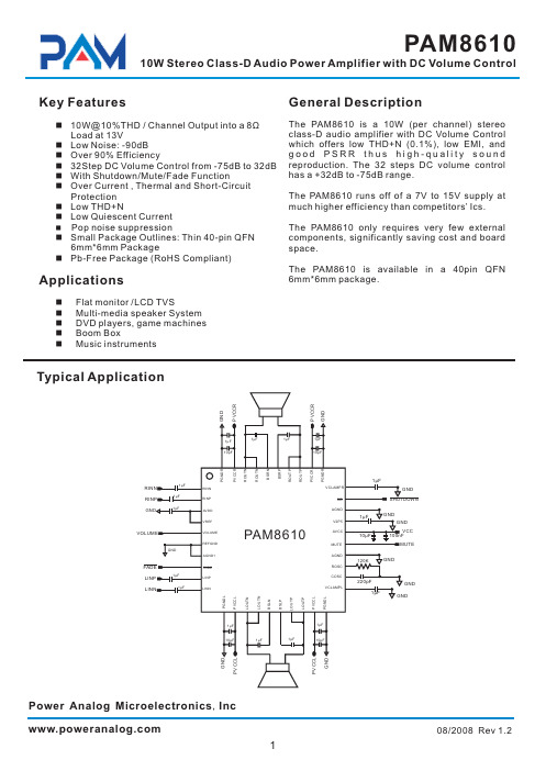
PAM8610
10W Stereo Class-D Audio Power Amplifier with DC Volume Control
Key Features
General Description
n 10W@10%THD / Channel Output into a 8Ω Load at 13V
Protection n Low THD+N n Low Quiescent Current n Pop noise suppression n Small Package Outlines: Thin 40-pin QFN
6mm*6mm Package n Pb-Free Package (RoHS Compliant)
31,40
PGNDR Power ground for right channel H-bridge
32,39
PVCCR Power supply for right channel H-bridge, not connected to PVCCL or AVCC.
33,34
ROUTP Class-D 1/2-H-bridge positive output for right channel
15
BSLN Bootstrap I/O for left channel, negative high-side FET
16
BSLP Bootstrap I/O for left channel, positive high-side FET
17,18
LOUTP Class-D 1/2-H-bridge positive output for left channel
Class-D功放详解全文

20KHz,小於開關頻率。
图2 原始信号和PWM输出信号以及经过低通滤
波器以后的信号频谱
6
第六页,共54页。
雖然Class-D Amplifier 的工作原理都 是依靠PWM調製技術,但在具體採樣方式
和時序上,各個廠商之間卻各不相同,以TI
& PAM為例:
右圖為TI廠商型號:TPA3110D2全橋 輸出的波形。黃色曲綫和藍色曲綫 分別為負載兩端對地的波形,紅色 曲綫為黃色曲綫與藍色曲綫做減法 運算得到的波形即負載的輸出波形。
則效率為:
•
E=RL/(2Ron + RL)
• 除外,偏置电流、输入电容充电、 和切换电流都会降低效率,右图为D
类放大器和AB类放大器在不同的输出 功率时的效率 。
NOTE:图上为效率是在输入为正弦波的情况下测
出的,而在实际的音乐条件下,效率就没有那么高
(75%左右),但依然要远高于AB类amplifier(是 Class-AB類的2.5~4倍)。
图7. 全橋式桥式输出的D类放大器
112 2 第十二页,共54页。
• 图8.半桥式和全桥式结构比较
113 3
第十三页,共54页。
Compare Class-D Amplifier With Class AB
114 4
第十四页,共54页。
Audio amplifier basic configuration
Nonlinear LC
PWM
Gate Driver
Modulation error
Quantization error
Dead time
Delay time
英国深海控制器 DSE8610调试人员专用说明
DSE8610 操作说明书
(内部资料)
深圳海汇科技有限公司
深圳市南山区南山大道2002号光彩新天地大厦8B1-8B2 电话:0755 2646 6606 传真:0755 2646 6609
深圳海汇科技有限公司
目录
章节
页数
1 控制器界面........................................................................................................3 2 按键...................................................................................................................3 3 LED 指示灯 .......................................................................................................4 4 选择模式 ...........................................................................................................5 5 操作模式 ...........................................................................................................5 6 浏览/查看控制器测量的各种参数.......................................................................6 7 排除故障 ...........................................................................................................8 8 控制器参数设置方法 .........................................................................................9
联想手机销售手册
联想手机销售手册Pam168销售手册一、产品理念和定位1、产品理念开放、时尚、个性化〔时尚的外观,目前世界上最轻、最薄的简体中文palmO掌上电脑,引导PDA的时尚潮流;开放式的操作系统提供成千上万的开放式应用软件;不同的用户,不同的应用和设置,造就更趋个性化、得心应手的产品〕轻松工作:超轻、超薄的外观设计,和开放式的PALMO及其应用作为内涵定义,对商务人士演奏出轻松便捷的工作旋律;多彩娱乐型PDA。
MP3和PDA的结合,表达PDA产品的休闲/娱乐应用方向,使更多的用户在更多的时间使用PDA产品。
生活:彩色TFT大屏幕,MP3、录音、电子书、红外短信、PC同步等功能的实现,为消费者引入多彩的视听生活享受;2、产品定位联想Pam168是国内中高端PDA市场中第一款真彩PalmO简体中文手写掌上电脑。
3.目标客户群用户群综合描述:Palm发烧友、外企员工、IT人士、送礼人士;年龄特征:22-45岁;用户核心需求:开放性应用+休闲娱乐+个人助理;典型目标用户:1〕刘先生,24岁,Palm发烧友,对Palm类产品有强烈的偏好;2〕John,某IT职员,熟悉计算机与网络,经常接触其他外企商业人士,对Palm类设备有了解;3〕王小姐,工作繁忙,需要PIM等功能来安排日程、管理时间,喜欢游戏、MP3、电子书等开放式数码应用以求工作之余的放松;4〕小方,需要一个PDA来送礼,但希望自己的PDA有独特之处,媒体和大家的评价是时尚产品;二、产品主要诉求①开放式操作系统②音乐游戏任我行③独有可隐藏“虚拟手写区”④真彩六万五千色TFT显示屏三.销售话术1、销售话述:根据对PALM类产品的认知度,我们把顾客分为两类:一类是普通顾客,一类是PALM发烧友。
针对不同类型顾客,我们介绍产品的话述不同。
〔1〕对普通顾客联想Pam168是国内第一款以PalmO为操作系统的掌上电脑,也是国内第一次引入国际最流行的PDA操作软件的新产品。
MX8610说明书

警告 (3)播放器外形和控制键 (5)附件 (8)安装电池 (9)液晶显示屏 (10)欣赏音乐 (11)语音录音 (13)模式按钮 (14)使用均衡器 (15)重放文件 (17)将软件安装到计算机 (19)MX 8610 Manager安装步骤 (20)将MP3播放器连接到计算机 (23)格式化内置内存 (24)将附加字体下载到MP3播放器中 (26)删除MP3播放器中的字体 (28)将文件传送到MP3播放器 (30)删除文件(在MP3播放器上) (33)删除文件(在计算机上) (34)设置重放顺序 (36)插入MMC和SD卡 (39)退出MMC和SD卡 (40)安全指南 (41)故障诊断 (42)产品技术规格 (43)- 1 -- 2 -为了避免失火与触电危险,请不要将播放器暴露在雨中或湿气中。
注意:为了避免触电危险,不要打开盖(或背面)。
机器内部无用户自己可以修理的零件。
如需修理,应由专业服务人员进行。
机器底板或背面的图形标记的含意如下。
等边三角形内的带箭头的闪电符号是用于提醒用户,产品外壳内有未绝缘的电压。
这个电压的幅度足以使人员触电。
等边三角形内的惊叹号用于提醒用户,部件上的文字说明是用于操作和维护(维修)的重要规则。
为了避免触电不要打开机匣。
仅专业人员可以维修。
注意如超出本手册的规定,对产品进行控制、调整或使用会导致有害的无线电辐射。
注意 有触电的危险不要打开耳机插孔锁定键音量调整麦克风录音(录语音)模式(快进/ 快退)(均衡器:X-LIVE/JAZZ/ROAK/FLA T/RETURN)(重复:简介/重复当前曲目/重复全部曲目/随机播放曲目/正常播放/返回)(删除:删除文件/返回)(存储器信息)(背光)开机/播放/暂停/关机液晶显示屏- 3 -电池盖和SD卡插槽插槽- 4 -- 5 -开机 - 按功能键(如果选择了“Hold (锁定)”键,按下“Fun ”键将没有作用!)播放-按一次功能键 暂停-按一次功能键 快进-按两次功能键 快倒-按三次功能键停止-按一次“Stop ”键 开机关机-按停止键,直到屏幕没有显示。
纽盾NDA 8610

一款电子产品
目录
01 主要参数
02 详细参数
纽盾NDA-8610是一款电子产品,端口类型是2*10/100/1000TX。
主要参数
端口类型:2*10/100/1000TX 吞吐量:6Gbps 用户数限制:1024 控制端口:Console接口 管理:Web管理,Telnet管理 电源电压:100VAC to 240VAC 50~60HZ 电源功率:200W 重量:10Kg 外观尺寸:440×286×44mm 工作温度:0℃-45℃工作湿度:0%~60% 存储温度:-40-80℃存储湿度:0%~95%Fra bibliotek详细参数
其他规格
主要规格
环境条件
端口类型 2*10/100/1000 TX 吞吐量:6Gbps 用户数限制:1024 控制端口:Console接口 冗余特性:不支持 管理:Web管理,Telnet管理 功能模块:流量分析及异常行为响应,用户通讯记录及事件报表,网络设备管理,MAC/IP配对管理,安全事件管 理,联合防御
电源电压:100VAC to 240VAC 50~60HZ 电源功率:200W 重量:10Kg 外观尺寸:440×286×44mm
环境条件工作温度:0℃-60℃ 工作湿度:0%~60% 存储温度:-40-80℃ 存储湿度:0%~95%
谢谢观看
PAM8610中文资料
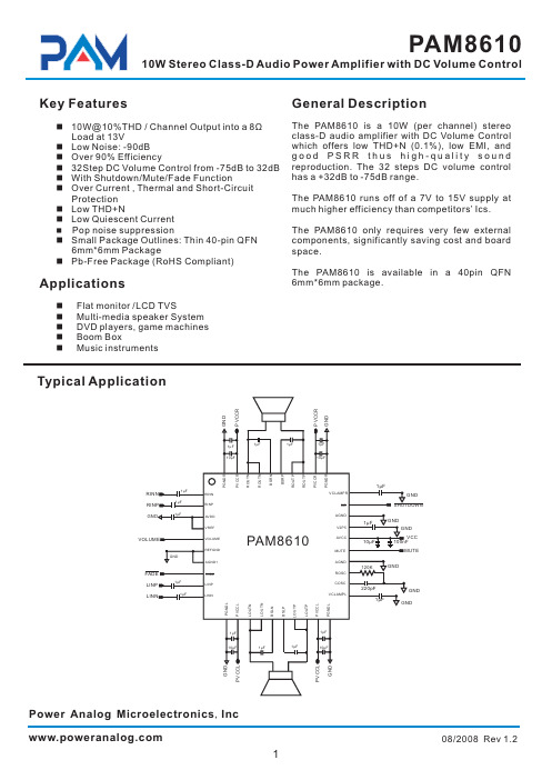
The PAM8610 is a 10W (per channel) stereo class-D audio amplifier with DC Volume Control which offers low THD+N (0.1%), low EMI, and good PSRR thus high-quality sound reproduction. The 32 steps DC volume control has a +32dB to -75dB range.
26
AVCC High-voltage analog power supply (7V to 15V)
2.5V Reference for analog cells, as well as reference for unused audio input
27
V2P5
when using single-ended inputs.
3
08/2008 Rev 1.2
元器件交易网
PAM8610
10W Stereo Class-D Audio Power Amplifier with DC Volume Control
Pin Descriptions
Pin Number Name
The PAM8610 is available in a 40pin QFN 6mm*6mm package.
n Flat monitor /LCD TVS n Multi-media speaker System n DVD players, game machines n Boom Box n Music instruments
5
DIY使用51单片机控制的PAM861010W10W数字功放我爱单片机

DIY使⽤51单⽚机控制的PAM861010W10W数字功放我爱单⽚机今天天⽓不错,⼜刮风⼜下⾬的。
据说适合发帖。
楼主是⼀个⾳响“爱好者”,从2822开始,2025,2003,2030陆续都做了⼀遍。
但是⼀直没有玩过传说中的数字功放。
⾃从论坛上推出PAM8610的数字功放板后,⼼就痒痒了。
⼀直想弄⼀⽚玩玩,坛⼦⼜正好举办单⽚机⽐赛,就想着做⼀个数字⾳量控制的数字功放参个赛。
数字功放嘛,⾳量还⽤电位器调节就有点OUT了。
攒够MM,去淘园兑换的时候却发现⽊有货了,只有那种集成了MP3解码的功放板,但这不是我想要的。
不能就这么放弃了吧,怎么办?幸好我们有万能的X宝,很容易就找到了这货,28元⼀⽚。
顺便买了⼀些乱七⼋遭的东东平衡⼀下运费。
本次DIY前后⼤概⽤了有⼀个⽉,过程是有点漫长的。
但是作为⼀名⾮专业的中年男⼈,有太多做不完的正经事情。
折腾这货只能利⽤晚上的空闲时间,熬夜是很正常滴,但是DIY的过程还是挺享受的。
先贴上⼀段视频,感兴趣的再往下看⼀、⼯欲善其事,必先美其壳⼀件DIY“作品”,电路做的再优秀,但是如果没有⼀个合适的外壳的话,效果也会⼤打折扣的。
外壳本来也是想买成品的,发现价格动辄上百,不符合DIY的精神。
于是找到⼀个有些年头的⼩壳⼦,⽐划⼀下发现⼤⼩也很合适。
就是太破旧了,不过这点⼩问题难不倒本“DIY达⼈”。
先⽤砂纸磨啊磨⽼产品就是厚道,这么厚的壳⼦现在还有吗?但是对于只有⼀只⼿电钻作为开孔设备的楼主来说,这绝对不是⼀件幸福的事。
我钻,我钻,我再钻……(其中断掉钻头N⽀)开孔后打磨好的样⼦⾃喷漆上阵,我喷……为了节约时间,“烤漆”中……喷好漆后的样⼦,⼀共喷了4~6遍,看起来挺光亮的。
最后涂了⼀遍清漆保护⼀下⽂件夹做的⾯板外壳基本完成⼆、热转印⼤*法+洞洞板混⾎PCB⾯板由于需要准确定位数码管与编码开关的位置,热转印怕搞不定。
⽼办法,OO板上场显⽰部分调试通过电路图腐蚀好的板⼦。
Class-D功放详解
• 图8.半桥式和全桥式结构比较
Compare Class-D Amplifier With Class AB
Audio amplifier basic configuration
Class-AB vs. Class-D
Class-AB amplifiers use the same push-pull architecture as class-B, but active devices are biased on with a small quiescent current when Vin = 0.
• NOTE:为了不失真地放大最高频率分量为 20KHz的音频信号,三角波的重复频率最好在十倍 音频的最高频率分量,也就是200KHz以上
右圖表明了一个1KHz的正 弦波音频信号,经过三角波 采样后的输出频谱,其中包 含有很多高频分量。在 PWM的输出后面加上一个 低通滤波器,就可以滤去矩 形波的高频分量。
advantage: excellent linearity
disadvantage: poor efficiency
Q4
Q3
Q5 Vin
PVDD
Q1
C1 Q2
Rload
Class-D amplifiers modulates the audio signal in to a high frequency PWM signal that drives the speaker(s).
fT=R8/4R6R7C4, VTP=V1R7/R8
图6. 三角波发生器
NOTE:积分电路的输出电压与输入 电压的积分成反比关系,所以阶跃信 号输入积分电路后会输出一个比例函 数的波形。
Class-D功放详解

Class D Vin
AP
LPF
AP
圖12 Test of Class-D and ClassAB
D类放大器的失真
Major Cause of Imperfection
Feedback Integrator
Switch nonidealities
Finite Ron Body diode Recovery (EMI)
最简单的PWM就是一个比较器,它的一端输入原始要放大的信号,另一端 就输入一个高频三角波。在这个比较器的输出就是一个脉宽被调制的矩形 波。这个矩形波就直接加到一对互补晶体管进行放大 。
NOTE:采用负反馈回路可降低失真,最简单的方式:直接从输出端经过RF反馈到输入端。
三角波可以采用如右图的方
式来产生。比较器输出的电 压为+V1和-V1。当输出电 压为-V1时,三角波以 m=V1/R6C4的斜率增长。假 定三角波的峰值幅度为从+ VTP到-VTP。再假定三角波 的周期为T=1/fT。那么2VTP =mT/2=V1/2fTR6C4。比较 器在其非倒相输入端的电压 达到0时,切换其状态。这发 生于V1/R8=VTP/R7。所以, 三角波的频率就等于
NOTE:死区时间会严重影响失真,时长 几十纳秒就可能导致THD达到1%以上。
图13 THD and Dead time
Power Supply Pumping
另一个导致THD增大的原因是总 线充电,可以在半桥拓扑向负载提 供低频的输出信号时观察到如右。 这主要是由于D类Amplifier的增益 与Vbus直接成比例关系,Vbus波 动造成输出失真。由于D类 Amplifier的开关时双向的,当大 量LPF电感储存的能量回流至电源 时,电源无法吸收从而导致Vbus 上升产生波动。
AuteX8610 说明书

手册约定
手册中有关图标的约定如下:
图标
警告
说明
这个图标主要是提醒用户,如果采用不正确的方式操作设备,可能会对人体或设备造成伤 害,或造成业务中断、数据丢失等。如安装过程、配置业务中等。
这个图标表示提醒用户注意事项。
注意
这个图标主要给出一些与正文相关的信息,同时给用户一些指引,协助用户更好的理解正
2 产品硬件结构 ...................................................................................................................................................................... 1 2.1 机箱结构 .................................................................................................................................................................. 1 2.1.1 前面板........................................................................................................................................................... 1 2.1.2 指示灯说明.................................................................................................................................................... 3 2.2 插槽结构 .................................................................................................................................................................. 3 2.2.1 AuteX8610 插槽描述..................................................................................................................................... 3 2.3 机架式模块............................................................................................................................................................... 4 2.3.1 AuteX8610 主控交换模块 ............................................................................................................................. 4 2.3.1.1 AX81-SMU模块概述 .......................................................................................................................... 4 2.3.1.2 AX81-SMU模块接口属性 ................................................................................................................... 4 2.3.1.3 AX81-SMU模块LED指示灯说明 ........................................................................................................ 4 2.3.2 12 端口 10/100/1000BASE-T和 12 端口 1000BASE-X业务板(AX-AC-12C)............................................. 5 2.3.2.1 AX-AC-12C模块概述 ......................................................................................................................... 5 2.3.2.2 AX-AC-12C模块接口属性 .................................................................................................................. 5 2.3.2.3 AX-AC-12C模块LED指示灯说明........................................................................................................ 6 2.3.3 8 端口 10/100/1000BASE-T和 8 端口 1000BASE-X业务板(AX-AC-8C)................................................... 6 2.3.3.1 AX-AC-8C模块概述 ........................................................................................................................... 6 2.3.3.2 AX-AC-8C模块的接口属性 ................................................................................................................ 7 2.3.3.3 AX-AC-8C模块LED指示灯说明.......................................................................................................... 7 2.3.4 2 端口 10GBASE-R、12 端口 10/100/1000BASE-T和 12 端口 1000BASE-X业务板(AX81-2X12G12S) ...... 8 2.3.4.1 AX81-2X12G12S模块概述 ................................................................................................................ 8 2.3.4.2 AX81-2X2G12S模块的接口属性........................................................................................................ 8 2.3.4.3 AX81-2X12G12S模块LED指示灯说明............................................................................................... 8
ClassD功放详解
Others:
THD+N (ex.0.01%, 80dBFs, A weighting Filter) Cross-Talk For Stereo
NOTE:死区时间会严重影响失真,时长 几十纳秒就可能导致THD达到1%以上。
图13 THD and Dead time
Power Supply Pumping
另一个导致THD增大的原因是总 线充电,可以在半桥拓扑向负载提 供低频的输出信号时观察到如右。 这主要是由于D类Amplifier的增益 与Vbus直接成比例关系,Vbus波 动造成输出失真。由于D类 Amplifier的开关时双向的,当大 量LPF电感储存的能量回流至电源 时,电源无法吸收从而导致Vbus 上升产生波动。
图7. 全橋式桥式输出的D类放大器
• 图8.半桥式和全桥式结构比较
Compare Class-D Amplifier With Class AB
Audio amplifier basic configuration
Class-AB vs. Class-D
Class-AB amplifiers use the same push-pull architecture as class-B, but active devices are biased on with a small quiescent current when Vin = 0.
完全工作于开关状态,損耗很小
只要考虑在导通时的损耗。假定
负载电阻为RL,晶体管导通时的 内阻为Ron,則效率為:
•
E=RL/(2Ron + RL)
• 除外,偏置电流、输入电容充 电、和切换电流都会降低效率,
右图为D类放大器和AB类放大器 在不同的输出功率时的效率 。
网络设备产品参数

安全产品技术规范杭州华三通信技术有限公司目录1.防火墙系列.......................................................................................................................................................1.1.M9000防火墙核心引导指标说明:...............................................................................................1.2.M9006..................................................................................................................................................1.3.M9010..................................................................................................................................................1.4.M9014..................................................................................................................................................1.5.新一代防火墙F50X0核心引导指标说明:..................................................................................1.6.F5040防火墙招标参数 .....................................................................................................................1.7.F5020防火墙招标参数 .....................................................................................................................1.8.F5000-S防火墙招标参数 .................................................................................................................1.9.F5000-C防火墙招标参数.................................................................................................................1.10.新一代F10X0防火墙核心引导指标说明:...............................................................................1.11.H3C SecPath F1020防火墙招标参数..............................................................................................1.12.H3C SecPath F1030防火墙招标参数..........................................................................................1.13.H3C SecPath F1050防火墙招标参数..........................................................................................1.14.H3C SecPath F1060防火墙招标参数..........................................................................................1.15.H3C SecPath F1070防火墙招标参数..........................................................................................1.16.H3C SecPath F1080防火墙招标参数..........................................................................................1.17.三款新千兆防火墙核心引导指标说明:...................................................................................1.18.F1000-E ...........................................................................................................................................1.19.F1000-E-SI ......................................................................................................................................1.20.F1000-A-EI .....................................................................................................................................1.21.F1000-S-AI......................................................................................................................................1.22.SecBlade FW Enhanced招标参数................................................................................................1.23.SecBlade FW招标参数 .................................................................................................................1.24.SecBlade FW Lite防火墙招标参数.............................................................................................1.25.新一代F1000-C-SI、F100-A/M-SI防火墙核心引导指标说明: ..........................................1.26.F1000-C-SI防火墙招标参数........................................................................................................1.27.F100-A-SI防火墙招标参数 .........................................................................................................1.28.F100-M-SI防火墙招标参数.........................................................................................................2.VPN系列.........................................................................................................................................................2.1.3.3.3.L1000-A...............................................................................................................................................4.流量分析NetStream (S75E、S95E、S105、S125配套)..........................................................................5.应用控制与审计网关ACG ...........................................................................................................................5.1.ACG 1000E(1G) .................................................................................................................................5.2.ACG 1000A(500M) ......................................................................................................................5.3.ACG 1000M(200M)......................................................................................................................5.4.ACG 1000S(30M) .........................................................................................................................5.5.ACG 1000C(10M).........................................................................................................................5.6.ACG 2000............................................................................................................................................5.7.ACG 8800............................................................................................................................................5.8.ACG 插卡(S75E、S95E、S105、S125配套) .........................................................................6.入侵防御IPS系列 .........................................................................................................................................6.1.IPS核心引导指标说明......................................................................................................................6.2.IPS T5000-S3 ......................................................................................................................................6.3.IPS T1000-A........................................................................................................................................6.4.IPS T1000-S ........................................................................................................................................6.5.IPS T1000-C........................................................................................................................................6.6.IPS T200-A..........................................................................................................................................6.7.IPS T200-M.........................................................................................................................................6.8.IPS T200-S ..........................................................................................................................................6.9.IPS 插卡(S125、S95E、S75E、S58、SR88、SR66配套) ...................................................7.UTM .................................................................................................................................................................7.1.UTM核心引导指标说明 ..................................................................................................................7.2.U200-A ................................................................................................................................................7.3.U200-M................................................................................................................................................7.4.U200-S.................................................................................................................................................7.5.UTM200-CA .......................................................................................................................................7.6.UTM200-CM.......................................................................................................................................7.7.UTM200-CS........................................................................................................................................1.防火墙系列防火墙整体引导策略:1、要求采用指定架构(M9000的分布式架构、中低端的多核非X86架构等),屏蔽和抬高友商。
深海控制器DSE8610功能介绍
深海控制器 DSE8610模块功能介绍DSE POWER® 优控系列 DSE8610 自启动负载分配模块一、DSE8610功能介绍 二、DSE8610监控方式一、DSE8610功能介绍1、 多端口可同时使用- RS232、 RS485、USB和网络端口 2、 具有数据采集和分析功能(data logging ) 3、 超强的PLC逻辑功能 4、 DSE8610模块的兼容性 5、 模块与调速器、调压板直接相连 6、 负载分配特性 7、 其他功能1、 多端口可同时使用- RS232、 RS485、网络端口、USB和程序设定端口2、 具有数据采集和分析功能(data logging )3、 超强的PLC逻辑功能举例:①当发动机的水温大于100°C,机组以额定功率的60%输出②当发动机的水温小于95°C,机组以额定功率的90%输出4、 DSE8610模块的兼容性5、 模块与调速器、调压板直接相连5.1 模块与调速器、调压板直接相连5.2 模块与数字调速器、数字调压板直接相连6、 负载分配特性6.1 自动模式下三种启动方式 ① 远程启动信号设置为Remote start on load ,无论哪台机组如果远程信号有效,都会自启动,然后并联。
接线如下图:② 远程启动信号设置为Remote start on load demand,根据负载 的大小,自动调用或停止除主机之外其它机组 。
接线如下图:软件设置如下图:③ 远程启动信号设置为Remote start on load demand,刚开始启动时,启动 所有的机组,然后根据负载的大小,自动调用或停止除主机之外其它机 组 。
接线如下图:软件设置如下图:6.2 削峰调节白天傍晚/黄昏晚上/夜间白天傍晚/黄昏晚上/夜间DSE8610负载分配百分比DSE8610负载分配百分比7、 其他功能7.1 可设4套工作模式和保护参数可预设4种工作模式和保护参数。
晶源集成电路 CSC8610

3
4 5 6 7 8 9 10 11、20 12、19 13、14 15 16 17、18 21 22 23 24、24 25 26 27
29
30 31、40 32、39 33、34
35 36 37、38
符号 RINN RINP
AVDD
VREF VOLUME REFGND AGND1
FADE LINP LINN PGNDL PVCCL LOUTN BSLN BSLP LOUTP VCLAMPL COSC ROSC AGND MUTE AVCC V2P5
SHUTDOWN,MUTE, FADE
最小值 最大值 单位
7
15
V
2
--
V
0
5
V
0
0.3
V
−25
85
℃
散热信息
热阻
Rth ( j-a) QFN40 Rth ( j-c) QFN40
18.1
℃/ W
7.6
℃/ W
电气参数(如无其它说明,TA = 25℃ ,VCC = 12V ,RL = 8Ω )
参数
符号
在7~15V的电源电压下具有很高的工作效 率。
无滤波设计使得CSC8610在应用仅需要很 少外围器件。
输出短路保护以防止同GND和VCC短路, 以及输出对输出短路,热保护保证器件不会超过 最大结温。
主要特点
z 在 13V 工作电压、8Ω 负载时输出功
典型应用
浪潮交换机硬件产品手册 SC6630EL-32C V1.0说明书

浪潮交换机硬件产品手册SC6630EL-32CV1.0尊敬的浪潮交换机用户:衷心感谢您选用浪潮交换机!本手册介绍了此款交换机的技术特性与系统的设置、安装,有助于您更详细地了解和便捷地使用此款交换机。
请将我方产品的包装物交废品收购站回收利用,以利于污染预防,造福人类。
浪潮拥有本手册的版权。
未经浪潮许可,任何单位和个人不得以任何形式复制本用户手册。
浪潮保留随时修改本手册的权利。
本手册中的内容如有变动恕不另行通知。
如果您对本手册有疑问或建议,请向浪潮垂询。
浪潮2021年8月是浪潮集团有限公司的注册商标。
本手册中提及的其他所有商标或注册商标,由各自的所有人拥有。
版本说明文档版本:V1.0日期:2021年8月文档说明:第1次正式发行。
摘要手册介绍本交换机的规格信息、硬件操作、服务条款、故障诊断等与维护工作密切相关的内容。
本指南认定读者对交换机产品有足够的认识,获得了足够的培训,在操作、维护过程中不会造成个人伤害或产品损坏。
目标受众本手册主要适用于以下人员:●技术支持工程师●产品维护工程师建议由具备交换机知识的专业工程师参考本手册进行交换机运维操作。
目录版本说明 (3)摘要 (4)目标受众 (4)1 安全说明 (7)2 产品规格介绍 (10)2.1 简介 (10)2.2特性和规格 (11)3 组件识别 (12)3.1前面板 (12)3.1.1组件 (12)3.1.2指示灯说明 (12)3.2后面板 (14)3.2.1组件 (14)3.2.2指示灯说明 (15)3.2.3 管理用户接口描述 (15)3.3电源模块 (16)3.3.1外观 (16)3.3.2功能 (16)3.3.3面板说明 (17)3.4风扇模块 (18)3.4.1外观 (18)3.4.2功能 (19)3.4.3面板说明 (19)4 安装前准备 (20)4.1环境要求 (20)4.1.1空间要求与通风要求 (20)4.1.2温度要求 (21)4.1.3电源要求 (21)4.1.4电气接地要求 (22)4.2机架警告 (22)4.3检查包装箱中的物品 (23)4.4准备工具 (24)5安装交换机 (24)5.1 安装前说明 (24)5.2工具和附件 (24)5.3安装接地线 (25)5.4安装交换机 (25)5.5连接接地线到机柜 (29)6 连接交换机 (29)6.1 操作和安全注意事项 (29)6.2 连接电源线 (30)6.3 连接高速线缆 (30)6.4 连接串口线缆 (30)7更换部件 (31)7.1更换电源模块 (31)7.2更换风扇模块 (31)8常见故障及诊断排除 (32)8.1常见硬件问题 (32)8.2诊断排除说明 (33)9 管制标准通告 (34)9.1中国通告 (34)10 静电放电 (34)10.1防止静电放电 (34)10.2防止静电释放的接地方法 (35)11服务条款 (35)1 安全说明警告:以下警告表示存在可能导致财产损失、人身伤害或死亡的潜在危险。
PAM8406规格书
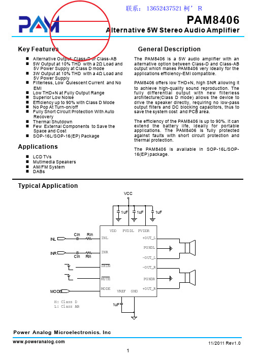
Thermal Information
Par ameter Thermal Resistance (Junction to AmbPackage S OP- 1 6
Maximum 110
Unit °C/W
T hermal Resis tance (Junction to Case)
VREF
OSC
CURRENT PROTECTION
M O D U L AT O R
-
DRIVER
+
+OUT_L -OUT_L
GND
Pin Configuration & Marking Information
PVDDL PGNDL
Top View SOP-16/SOP-16(EP)
+OUT_L 1
16 +OUT_R
Recovery n Thermal Shutdown n Few External Components to Save the
Space and Cost n SOP-16L/SOP-16(EP) Package
Applications
n LCD TVs n Mutimedia Speakers n AM/FM System n DABs
(Class D) VDD=3.6V,Po=0.05W~1W,RL=2 Ω
(Class D)
PSRR Power Supply R ipple Rejection VDD=5.0V, Inputs ac- grounded with
Cs SNR
Crosstalk Signal- to-noise ratio
PGNDL 2
15 PGNDR
AW8610LGR_产品手册
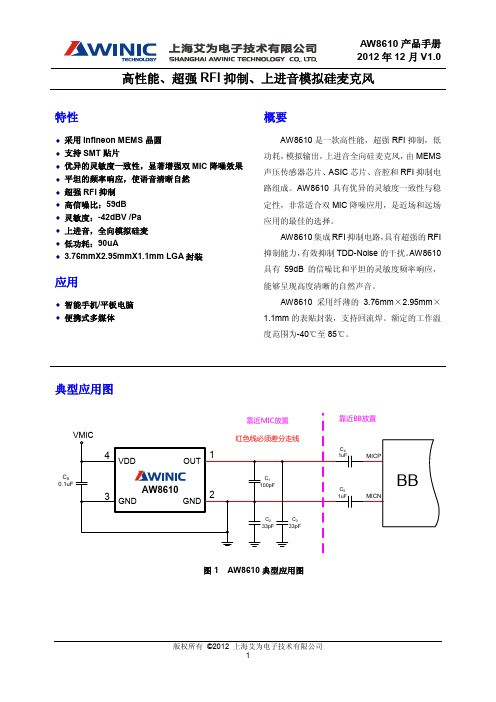
版权所有 ©2012 上海艾为电子技术有限公司 2
AW8610 产品手册 2012 年 12 月 V1.0
高性能、超强 RFI 抑制、上进音模拟硅麦克风
8.3 MEMS 麦克风线控耳机应用 .................................................................................................................. 16 8.4 MEMS 麦克风 RFI 抑制 ......................................................................................................................... 17 8.5 PCB 焊盘尺寸 ........................................................................................................................................ 18 8.6 钢网尺寸 ................................................................................................................................................ 19 9 MEMS 麦克风结构设计建议 ......................................................................................................................... 19 9.1 声学结构设计建议 ................................................................................................................................. 19 9.2 防尘结构设计建议 ................................................................................................................................. 20 10 使用说明 ..................................................................................................................................................... 21 11 封装描述 ..................................................................................................................................................... 23 11.1 卷带描述 .............................................................................................................................................. 23 11.2 封装描述 .............................................................................................................................................. 24 11.3 回流焊曲线 .......................................................................................................................................... 25 12 可靠性规格 ................................................................................................................................................. 26 13 版本修订记录.............................................................................................................................................. 27
- 1、下载文档前请自行甄别文档内容的完整性,平台不提供额外的编辑、内容补充、找答案等附加服务。
- 2、"仅部分预览"的文档,不可在线预览部分如存在完整性等问题,可反馈申请退款(可完整预览的文档不适用该条件!)。
- 3、如文档侵犯您的权益,请联系客服反馈,我们会尽快为您处理(人工客服工作时间:9:00-18:30)。
A Product Line ofDiodes Incorporated10W STEREO CLASS-D AUDIO POWER AMPLIFIER WITH DC VOLUME CONTROLDescriptionThe PAM8610 is a 10W (per channel) stereo Class-D audio amplifier with DC Volume Control which offers low THD+N (0.1%), low EMI, and good PSRR thus high-quality sound reproduction. The 32 steps DC volume control has a +32dB to -75dB range.The PAM8610 runs off of a 7V to 15V supply at much higher efficiency than competitors’ ICs.The PAM8610 only requires very few external components, significantly saving cost and board space.The PAM8610 is available in a 40pin QFN 6mm*6mm package.Features∙ 10W @ 10%THD/Channel Output into a 8Ω Load at 13V ∙ Low Noise: -90dB ∙ Over 90% Efficiency∙ 32 Step DC Volume Control from -75dB to +32dB ∙ With Shutdown/Mute/Fade Function ∙ Over Current , Thermal and Short-Circuit Protection ∙ Low THD+N∙ Low Quiescent Current ∙ Pop Noise Suppression∙ Small Package Outlines: Thin 40-pin QFN 6mm*6mm Package ∙Pb-Free Package (RoHS Complaint)Pin AssignmentsApplications∙ Flat Monitor /LCD TVS ∙ Multi-Media Speaker System ∙DVD Players, Game Machines∙ Boom Box ∙ Music InstrumentsTypical Applications CircuitEdited by Foxit ReaderCopyright(C) by Foxit Software Company,2005-2008For Evaluation Only.Pin DescriptionsFunctional Block DiagramAbsolute Maximum Ratings (@T A = +25°C, unless otherwise specified.)These are stress ratings only and functional operation is not implied. Exposure to absolute maximum ratings for prolonged time periods may affect device reliability. All voltages are with respect to ground.Recommended Operating Conditions(@T A = +25°C, unless otherwise specified.)Thermal InformationParameter PackageSymbolMaxUnitThermal Resistance (Junction to Ambient) QFN6mm*6mm θJA18.1°C/WThermal Resistance (Junction to Case) QFN6mm*6mm θJC7.6The Exposed PAD must be soldered to a thermal land on the PCB.Electrical Characteristics (@T A = +25°C, V DD = 12V, R L = 8Ω, unless otherwise specified.)Parameter Symbol TestConditions MinTypMaxUnits Supply Voltage V DD7.0 12 15 VContinuous Output Power P O THD+N = 0.1%, f = 1kHz, R L = 8Ω 5W THD+N = 1.0%, f = 1kHz, R L = 8Ω 8 THD+N = 10%, f = 1kHz, R L = 8Ω,V DD = 13V10 THD+N = 0.1%, f = 1kHz, R L = 4Ω (Note 3) 15Total Harmonic Distortion plus Noise THD+N P O = 5W, f = 1kHz, R L = 8Ω 0.1 % Quiescent Current I DD No Load 20 30 mA Supply Quiescent Current inShutdown Mode I SDShutdown = 0V 4 10 µADrain-Source On-State Resistance R DS(ON)V CC = 12VI O = 1AT J = +25°CHigh Side 200mΩLow Side 200Total 400Power Supply Ripple Rejection PSRR 1V PP Ripple, f = 1kHz,Inputs AC-Coupled to Ground-60 dBOscillator Frequency f OSC R OSC = 120kΩ, C OSC = 220pF 250 kHz Output Integrated Noise Floor VN 20Hz to 22kHz, A-Weighting -90 dB Crosstalk CS P O = 3W, R L = 8Ω, f = 1kHz -80 dBSignal to Noise Ratio SNR Maximum output at THD+N < 0.5%,f = 1kHz80 dBOutput Offset Voltage(measured differentially)|V OS| INN and INP connected together 30 mV 2.5V Bias Voltage V2P5 No Load 2.5 V Internal Analog Supply Voltage AV DD V DD = 7V to 15V 5.0 5.5 V Over Temperature Shutdown OTS 150 °C Thermal Hysteresis OTH 40 °CTypical Performance Characteristics (@T A = +25°C, V DD = 12V, R L = 8Ω, G V = 24dB, unless otherwise specified.)Typical Performance Characteristics (cont.) (@T A = +25°C, V DD = 12V, R L = 4Ω, G V = 24dB, unless otherwise specified.)Typical Performance Characteristics (cont.) (@T A = +25°C, V DD = 12V, R L = 8Ω, G V = 24dB, unless otherwise specified.)Typical Performance Characteristics (cont.) (@T A = +25°C, V DD = 12V, R L = 8Ω, G V = 24dB, unless otherwise specified.)Notes: PCB information for power dissipation measurement.1. The PCB size is 74mm 68mm with 1.2mm thickness, two layers and Fr4.2. 16 vias at the thermal land on the PCB with 0.5mm diameter.3. The size of exposed copper is 10mm*10mm with 3oz thickness.Application InformationTest Setup for Performance TestingNotes: 4. The AP AUX-0025 low pass filter is necessary for class-D amplifier measurement with AP analyzer.5. Two 22μH inductors are used in series with load resistor to emulate the small speaker for efficiency measurement.Power and Heat DissipationChoose speakers that are able to stand large output power from the PAM8610. Otherwise, speaker may suffer damage.Heat dissipation is very important when the device works in full power operation. Two factors affect the heat dissipation, the efficiency of the device that determines the dissipation power, and the thermal resistance of the package that determines the heat dissipation capability.In operation, some of power is dissipated to the resistors.Power Dissipation: P LOSS = (P O*(1-η/η)*2The PAM8610’s efficiency is 90% with 10W ouput and 8Ω load. The dissipation power is 2.22W.Thermal resistance of junction to ambient of the QFN package is 18.1°C/W and the junction temperature T J = P LOSS * θJA+T A, where T A is ambient temperature. If the ambient temperature is +85°C, the QFN’s junction temperatureT J = 2.22*18.1 + 85 = +125°Cwhich is lower than +150°C rated junction temperature.If the rated workable junction temperature is 150°C, the relat ionship between ambient temperature and permitted P LOSS is shown in below diagram.From the diagram, it can be found that when the device works at 10W/8Ω load the dissipation power is 1.1W per channel, 2.2W total, the permitted ambient temperature is over 100°C. This is proven by actual test. The PAM8610 can work in full output power under +85°C ambient temperature.Application Information (cont.)Heat Dissipation in PCB DesignGenerally, class-D amplifiers are high efficiency and need no heat sink. For high power ones that has high dissipation power, the heat sink may also not necessary if the PCB is carefully designed to achieve good heat by the PCB itself.Dual-Side PCBTo achieve good heat, the PCB’s copper plate should be thicker than 0.035mm and both sides of the PCB should be utilized for heat sink.The thermal pad on the bottom of the device should be soldered to the plate of the PCB, and via holes, usually 9 to 16, should be drilled in the PCB area under the device and deposited copper on the vias should be thick enough so that the heat can be dissipated to the other side of the plate. There should be no insulation mask on the other side of the copper plate. It is better to drill more vias around the device if possible.4-Layer PCBIf it is 4-layer PCB, the two middle layers of grounding and power can be employed for heat dissipation, isolating them into serval islands to avoid short between ground and power.Consideration for EMIFilters are not required if the traces from the amplifier to the speakers are short (<20cm). But most applications require a ferrite bead filter as shown in below figure. The ferrite bead filter reduces EMI of around 1MHz and higher to meet the FCC and CE's requirements. It is recommended to use a ferrite bead with very low impedances at low f requenc ies and high impedance at high frequencies (above 1MHz).The EMI characteristics are as follows after employing the ferrite bead.Application Information (cont.)Volume ControlA DC volume control section is integrated in PAM8610, controlling via V REF, VOLUME and V REFGND terminals. The voltage on VOLUME pin, without exceeding V REF, determines internal amplifier gain as listed in Table 1.If a resistor divider is used to fix gain of the amplifier, the V REF terminal can be directly connected to AV DD and the resistor divider connected across V REF and REFGND. For fixed gain, the resistor divider values are to center the voltage given in the Table 1.FADE OperationThe FADE terminal is a logic input that controls the operation of the volume control circuitry during transitions to and from the shutdown state and during power-up.A logic low on this terminal will set the amplifier in fade mode. During power-up or recovery from the shutdown state (a logic high is applied to the SD terminal), the volume is smoothly ramped up from the mute state, -75dB, to the desired volume set by the voltage on the volume control terminal. Conversely, the volume is smoothly ramped down from the current state to the mute state when a logic low is applied to the SD terminal. A logic high on this pin disables the volume fade effect during transitions to and from the shutdown state and during power-up. During power-up or recovery from the shutdown state (a logic high is applied to the SD terminal), the transition from the mute state, -75dB, to the desired volume setting is less than 1ms. Conversely, the volume ramps down from current state to the mute state within 1ms when a logic low is applied to the SD terminal.MUTE OperationThe MUTE pin is an input for controlling the output state of the PAM8610. A logic high on this pin disables the outputs and low enables the outputs. This pin may be used as a quick disable or enable of the outputs without a volume fade.For power saving, the SD pin should be used to reduce the quiescent current to the absolute minimum level. The volume will fade, increasing or decreasing slowly, when leaving or entering the shutdown state if the FADE terminal is held low. If the FADE terminal is held high, the outputs will transit very quickly. Refer to the FADE operation section.Shutdown OperationThe PAM8610 employs a shutdown operation mode to reduce supply current to the absolute minimum level during periods of non-use to save power. The SD input terminal should be held high during normal operation when the amplifier is in use. Pulling SD low causes the outputs to mute and the amplifier to enter a low-current state. SD should never be left unconnected to prevent the amplifier from unpredictable operation.For the best power-off pop performance, the amplifier should be set in shutdown mode prior to removing the power supply voltage.Internal 2.5V Bias Generator Capacitor SelectionThe internal 2.5V bias generator (V2P5) provides the internal bias for the preamplifier stage. The external input capacitors and this internal reference allow the inputs to be biased within the optimal common-mode range of the input preamplifiers.The selection of the capacitor value on the V2P5 terminal is critical for achieving the best device performance. During startup or recovery from shutdown state, the V2P5 capacitor determines the rate at which the amplifier starts up. When the voltage on the V2P5 capacitor equals 0.75 x V2P5, or 75% of its final value, the device turns on and the Class-D outputs start switching. The startup time is not critical for the best de-pop performance since any heard pop sound is the result of the Class-D output switching-on other than that of the startup time. However, at least a 0.47μF capacitor is recommended for the V2P5 capacitor.Another function of the V2P5 capacitor is to filter high frequency noise on the internal 2.5V bias generator.Power Supply Decoupling, C SThe PAM8610 is a high-performance CMOS audio amplifier that requires adequate power supply decoupling to ensure the output total harmonic distortion (THD) as low as possible. Power supply decoupling also prevents oscillations caused by long lead between the amplifier and the speaker. The optimum decoupling is achieved by using two capacitors of different types that target different types of noise on the power supply leads. For higher frequency transients, spikes, or digital hash on the line, a good low equivalent-seriesresistance(ESR) ceramic capacitor, typically 1μF, is recommended, placing as close as possible to the device’s V CC lead. To filter lower-frequency noises, a large aluminum electrolytic capacitor of 10μF or greater is recommended, placing near the audio power amplifier. The 10μF capacitor also serves as a local storage capacitor for supplying current during large signal transients on the amplifier outputs.Application Information (cont.)Selection of COSC and ROSCThe switching frequency is determined by the values of components connected to R OSC (pin 23) and C OSC (pin 22) and calculated as follows:f OSC = 2π/ (R OSC * C OSC)The frequency may varies from 225kHz to 275kHz by adjusting the values of R OSC and C OSC. The recommended values are C OSC = 220pF, R OSC = 120kΩ for a switching frequency of 250kHz.BSN and BSP CapacitorsThe full H-bridge output stages use NMOS transistors only. They therefore require bootstrap capacitors for the high side of each output to turn on correctly. At least 220nF ceramic capacitor, rated for at least 25V, must be connected from each output to its corresponding bootstrap input. Specifically, one 220nF capacitor must be connected from xOUTP to xBSP, and another 220nF capacitor from xOUTN to xBSN. It is recommended to use 1µF BST capacitor to replace 220nF (pin15, pin 16, pin 35 and pin 36) for lower than 100Hz applications.VCLAMP CapacitorsTo ensure that the maximum gate-to-source voltage for the NMOS output transistors not exceeded, two internal regulators are used to clamp the gate voltage. Two 1μF capacitors must be connected from VCLAMPL and VCLAMPR to ground and must be rated for at least 25V. The voltagesat the VCLAMP terminals vary with V CC and may not be used to power any other circuitry.Internal Regulated 5-V Supply (AVDD)The AVDD terminal is the output of an internally generated 5V supply, used for the oscillator, preamplifier, and volume control circuitry. It requires a 0.1μF to 1μF capacitor, placed very close to the pin to ground to keep the regulator stable. The regulator may not be used to power any external circuitry.Differential InputThe differential input stage of the amplifier eliminates noises that appear on the two input lines of the channel. To use the PAM8610 with a differential source, connect the positive lead of the audio source to the INP input and the negative lead from the audio source to the INN input. To use the PAM8610 with a single-ended source, acground the INP input through a capacitor equal in value to the input capacitor on INN and apply the audio source to the INN input. In a single-ended input application, the INP input should be acgrounded at the audio source other than at the device input for best noise performance.Using Low-ESR CapacitorsLow- ESR capacitors are recommended throughout this application section. A real (with respect to ideal) capacitor can be modeled simply as a resistor in series with an ideal capacitor. The voltage drop across this resistor minimizes the beneficial effects of the capacitor in the circuit. The lower the equivalent value of this resistance the more the real capacitor behaves as an ideal capacitor.Short-Circuit ProtectionThe PAM8610 has short circuit protection circuitry on the outputs to prevent damage to the device when output-to-output shorts, output-to-GND shorts, or output-to-V CC shorts occur. Once a short-circuit is detected on the outputs, the output drive is immediately disabled. This is a latched fault and must be reset by cycling the voltage on SD the pin to a logic low and back to the logic high state for normal operation. This will clear the short-circuit flag and allow for normal operation if the short was removed. If the short was not removed, the protection circuitry will again activate.Thermal ProtectionThermal protection on the PAM8610 prevents damage to the device when the internal die temperature exceeds +150°C. There is a ±15 degree tolerance on this trip point from device to device. Once the die temperature exceeds the set thermal point, the device enters into the shutdown state and the outputs are disabled. This is not a latched fault. The thermal fault is cleared once the temperature of the die is reduced by 40°C. The device begins normal operation at this point without external system intervention.Ordering InformationPart Number Part Marking Package TypeStandard PackagePAM8610TRPAM8610XATYWWLLQFN6x6-40 2500 Units/Tape&ReelMarking InformationPackage Outline Dimensions (All dimensions in mm.) QFN6x6-40IMPORTANT NOTICEDIODES INCORPORATED MAKES NO WARRANTY OF ANY KIND, EXPRESS OR IMPLIED, WITH REGARDS TO THIS DOCUMENT, INCLUDING, BUT NOT LIMITED TO, THE IMPLIED WARRANTIES OF MERCHANTABILITY AND FITNESS FOR A PARTICULAR PURPOSE (AND THEIR EQUIVALENTS UNDER THE LAWS OF ANY JURISDICTION).Diodes Incorporated and its subsidiaries reserve the right to make modifications, enhancements, improvements, corrections or other changes without further notice to this document and any product described herein. Diodes Incorporated does not assume any liability arising out of the application or use of this document or any product described herein; neither does Diodes Incorporated convey any license under its patent or trademark rights, nor the rights of others. Any Customer or user of this document or products described herein in such applications shall assume all risks of such use and will agree to hold Diodes Incorporated and all the companies whose products are represented on Diodes Incorporated website, harmless against all damages.Diodes Incorporated does not warrant or accept any liability whatsoever in respect of any products purchased through unauthorized sales channel. Should Customers purchase or use Diodes Incorporated products for any unintended or unauthorized application, Customers shall indemnify and hold Diodes Incorporated and its representatives harmless against all claims, damages, expenses, and attorney fees arising out of, directly or indirectly, any claim of personal injury or death associated with such unintended or unauthorized application.Products described herein may be covered by one or more United States, international or foreign patents pending. Product names and markings noted herein may also be covered by one or more United States, international or foreign trademarks.This document is written in English but may be translated into multiple languages for reference. Only the English version of this document is the final and determinative format released by Diodes Incorporated.LIFE SUPPORTDiodes Incorporated products are specifically not authorized for use as critical components in life support devices or systems without the express written approval of the Chief Executive Officer of Diodes Incorporated. As used herein:A. Life support devices or systems are devices or systems which:1. are intended to implant into the body, or2. support or sustain life and whose failure to perform when properly used in accordance with instructions for use provided in thelabeling can be reasonably expected to result in significant injury to the user.B. A critical component is any component in a life support device or system whose failure to perform can be reasonably expected to cause thefailure of the life support device or to affect its safety or effectiveness.Customers represent that they have all necessary expertise in the safety and regulatory ramifications of their life support devices or systems, and acknowledge and agree that they are solely responsible for all legal, regulatory and safety-related requirements concerning their products and any use of Diodes Incorporated products in such safety-critical, life support devices or systems, notwithstanding any devices- or systems-related information or support that may be provided by Diodes Incorporated. Further, Customers must fully indemnify Diodes Incorporated and its representatives against any damages arising out of the use of Diodes Incorporated products in such safety-critical, life support devices or systems.Copyright © 2012, Diodes Incorporated。
