LT1E77A中文资料
数据手册_HR7P187_Datasheet_C V2.1

加强描述:3.2.3,5.1.4,6.1.3,6.5.1,6.5.2, 附录 1.1,附录 2.1,附录 2.2
错误修正:2.1,2.2,4.3,5.1.1.1,5.1.1.2,5.1.2.1, 5.1.2.2,5.4.3,附录 1.3,附录 1.4
V2.1 版权所有©上海海尔集成电路有限公司
4/85
V2.1 版权所有©上海海尔集成电路有限公司
3/85
上海海尔集成电路有限公司
HR7P187 数据手册
版本 V1.0 V2.0
V2.1
修改日期 2010-08-02 2011-03-11
2011-04-26
修订历史
预发行版
更改概要
添加内部时钟电气特性及部分补充说明
2/85
上海海尔集成电路有限公司
HR7P187 数据手册
产品订购信息
型号
程序存储器
HR7P187F4R HR7P187F4R-B
HR7P187F4D HR7P187F4D-B FLASH:2K×15 位
HR7P187F4S HR7P187F4S-B
数据存储器
版权所有©
上海海尔集成电路有限公司
本数据手册的信息在发行时是经过核实并且尽最大努力使之精确的。上海海尔集成电路有限公司不为由于使用本数 据手册而可能带来的风险或后果负责。手册中的实例仅作为说明用途,上海海尔集成电路有限公司不担保或确认这 些实例是合适的、不需进一步修改的、或推荐使用的。上海海尔集成电路有限公司保留不需要通知本数据手册读者 而修改自己产品的权利。如需得到最新的产品信息,请随时用上述联系方式与上海海尔集成电路有限公司联系。
上海海尔集成电路有限公司
HR7P187 数据手册
CT117E使用说明书
PB10 PB11
SD1
SPI 功能连接到 SD 卡座;
SD2
断开:用作外部扩展
PB12
SD3
PB15
SD_CMD
PB13
SD_CLK
5
I2C
PB6
SCL
短接:处理器第一 I2C 功能连接到板上 I2C 器件;
PB7
SDA
断开:用作外部扩展
6 LED 锁存
PD2
573 锁存脚 短接:连接到板上 LED 锁存器的锁存脚,把 PC8~PC15 的数
... // 蜂鸣器响 GPIO_SetBits(GPIOB,GPIO_Pin_4);
... // while(1);
6
(2)单击 Settings 选项,在 Debug 的 Adapter 下拉菜单中选择 Colink;
(3)单击 Settings 选项在 Flash Download 选项中单击 ADD;选择 STM32 中密度产品;
5
(4)在 “Options for Target”的 Utilities 选项中选择 CooCox Debugger;
(5)完成以上配置后,即可使用板载调试功能。
6
3. 程序调试说明
CT117E 设计中,使用了 JTAG-RST 引脚(PB4)连接蜂鸣器,引脚上电默认配置为 JTAG 引脚,调试程序时,需要将蜂鸣器跳线(红色跳线帽)取下。STM32 的 JTAG 引脚可重映 射为 GPIO 使用,使用方法如下:
// 固件库 V3.50 // 时钟使能 RCC_APB2PeriphClockCmd(RCC_APB2Periph_AFIO,ENABLE); RCC_APB2PeriphClockCmd(RCC_APB2Periph_GPIOB,ENABLE); // GPIO_PinRemapConfig(GPIO_Remap_SWJ_NoJTRST,ENABLE); // GPIO 引脚配置 GPIO_Configuration ();
pl6517a技术规格书

pl6517a技术规格书全文共四篇示例,供您参考第一篇示例:技术规格书是一份非常重要的文件,它详细描述了特定产品或设备的技术参数、性能特点和规格要求,对于产品的设计、制造和应用都有着重要的指导和规范作用。
PL6517A技术规格书就是描述了PL6517A产品的技术参数、性能特点和规格要求的文件。
本文将对PL6517A技术规格书进行详细的介绍和解析。
一、产品概述PL6517A是一款高性能的数字信号处理器,主要用于音频处理和音频信号解码。
它采用了先进的数字信号处理技术,能够实现高效、精确的信号处理和解码,广泛应用于音响设备、汽车音响、智能家居等领域。
产品具有体积小、功耗低、性能稳定等特点,是当前市场上颇受欢迎的音频处理芯片之一。
二、技术参数1. 工作电压:3.3V2. 工作温度:-40℃~85℃3. 输入端口:双通道模拟输入、SPDIF数字输入4. 输出端口:双通道模拟输出、I2S数字输出5. 稳定性:±0.1dB6. 信噪比:120dB7. 总谐波失真:-110dB以上是PL6517A的主要技术参数,从这些参数可以看出,PL6517A具有工作电压低、工作温度范围广、输出稳定性高、信噪比高等优秀的特点,非常适合于高要求的音频处理场景。
三、性能特点1. 高精度信号处理能力:PL6517A内置了先进的数字信号处理算法,能够对音频信号进行高精度的处理和解码,保证了音质的优异性能。
2. 低功耗设计:PL6517A采用了先进的低功耗设计,使得产品在高性能的能够保持较低的功耗水平,有利于节能环保。
3. 稳定可靠:PL6517A使用稳定可靠的硬件和软件设计,经过严格的测试和验证,可以确保产品在各种复杂环境下稳定运行。
四、应用领域PL6517A数字信号处理器适用于多种领域,主要包括但不限于以下几个方面:1. 高端音响设备:PL6517A能够提供高品质的音频处理和解码功能,适用于高端家庭音响、专业音响设备等领域。
BAV70LT1中文资料
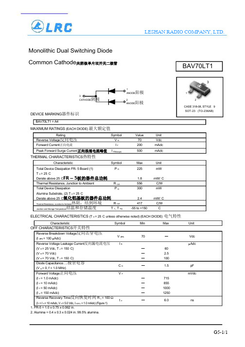
LESHAN RADIO COMPANY, LTD. Monolithic Dual Switching DiodeCommon Cathode共阴极单片双开关二极管3CATHODE阴极DEVICE MARKING器件标识BAV70LT131ANODE阳极 12 2ANODE阳极CASE 318-08, STYLE 9SOT-23 (TO-236AB)BAV70LT1 = A4MAXIMUM RATINGS (EACH DIODE) 最大额定值Rating Symbol Value Unit Reverse Voltage反向电压V R 70 VdcForward Current正向电流I F 200 mAdcPeak Forward Surge Current正向浪涌电流峰值I FM(surge) 500 mAdcTHERMAL CHARACTERISTICS热特性Characteristic Symbol Max Unit Total Device Dissipation FR- 5 Board (1) P D 225 mWT A = 25°CDerate above 25°C FR – 5板的器件总功耗 1.8 mW/°CThermal Resistance, Junction to Ambient R θJA 556 °C/WTotal Device Dissipation P D 300 mWAlumina Substrate, (2) T A = 25°CDerate above 25°C氧化铝基板的器件总功耗 2.4 mW/°CThermal Resistance, Junction to Ambient热阻,结到环境R θJA 417 °C/WJunction and Storage Temperature结温和存储温度T J , T stg -55 to +150 °CELECTRICAL CHARACTERISTICS (T A = 25°C unless otherwise noted) (EACH DIODE)电气特性Characteristic Symbol Min Max Unit OFF CHARACTERISTICS开关特性Reverse Breakdown Voltage反向击穿电压(I (BR) = 100 µAdc)Reverse Voltage Leakage Current反向漏电流电压(V R = 25 Vdc, T J = 150°C)(V R = 70 Vdc)(V R = 70 Vdc, T J = 150°C)Diode Capacitance二极管电容(V R = 0, f = 1.0 MHz) V (BR) 70 —VdcI R µAdc—60— 2.5—100C D — 1.5 pFForward Voltage正向电压(I F = 1.0 mAdc)(I F = 10 mAdc)(I F = 50 mAdc)(I F = 150 mAdc)Reverse Recovery Time反向恢复时间 R L = 100 Ω(I F = I R = 10 mAdc, V R = 5.0 Vdc, I R(REC) = 1.0 mAdc) (Figure 1) V F mVdc—715—855—1000—1250t rr — 6.0 ns1. FR-5 = 1.0 x 0.75 x 0.062 in.2. Alumina = 0.4 x 0.3 x 0.024 in. 99.5% alumina.G5-1/1。
TH2817A 说明书

第一章概述感谢您购买和使用我公司产品,在您使用本仪器前首先请根据说明书最后一章“成套和保修”的事项进行确认,若有不符请尽快与我公司联系,以维护您的权益。
1.1 引言TH2817A型精密LCR数字电桥是一种高精度、高稳定性、宽测试范围的由十六位微处理器控制的阻抗测量仪器。
可以选择50Hz~100kHz之间的十六个典型测试频率,并可选择0.01V~2.00V之间以0.01V步进的测试信号电平,可以测量电感L、电容C、电阻R等多种参数。
本仪器功能强大、性能优越,并且采用液晶屏显示,显示明了,操作菜单化,快捷方便,能很好的适应生产现场快速检验的需要以及实验室高精确度高稳定度的测量需要,同时仪器所提供的HANDLER接口、IEEE488(选件)接口及RS232C接口为仪器使用于自动分选系统和计算机远程操作提供了条件。
仪器提供了多种可变的测试条件,典型的有:z测试频率: 纯正弦波50Hz、60Hz、100Hz、120Hz、200Hz、400Hz、500Hz、1kHz、2kHz、4kHz、5kHz、10kHz、20kHz、40kHz、50kHz、100kHz十六个典型频率;z测试信号电平: 从0.01V~2.00V以0.01V步进;z测试速度: 可以选择快速、中速、慢速三种速度,同时可进行1~255次可编程的平均次数来提高读数稳定性;z偏置电流: 可控制外部偏置电流源(如TH1773)进行偏流扫描叠加测试;z清“0”: 仪器可对测试端进行开路或短路的点频或扫频清“0”,将存在于仪器测试端的杂散电容和引线电阻消除以进一步提高测量精度;z测试信号监视: 实际施加于被测件上的测试信号也许由于被测阻抗与源阻抗之间的失配而与编程设置不一致,仪器可将施加于被测件上的电压与实际流过被测件上的电流在显示器上显示出来;z列表扫描: 可最多对4点频率或4点电压进行列表扫描,当与外部偏置电流源(如TH1773)连接并启动后,可进行4点偏流下的参数扫描测试。
3717A芯片参数

April 1993
1/11
PBL3717A
PIN FUNCTIONS
N°
Name
Function
1
UTPUT B
Output Connection (with pin 15). The output stage is a ”H” bridge formed by four
transistors and four diodes suitable for switching applications.
printed circuit copper.
5
GROUND
See pin 4.
6
LOGIC SUPPLY Supply Voltage Input for Logic Circuitry
7
INPUT 1
This pin and pin 9 (INPUT 0) are logic inputs which select the outputs of the
THERMAL DATA
Symbol
Parameter
Rth j-case Thermal Resistance Junction-pins
Rth j-amb Thermal Resistance Junction-ambient*
* Soldered on a 35µ thick 20 cm2 P.C. board copper area.
. FULL STEP - HALF STEP - QUARTER STEP OPERATING MODE
. BIPOLAR OUTPUT CURRENT UP TO 1 A . FROM 10 V UP TO 46 V MOTOR SUPPLY
IL711-1E中文资料

IsoLoop is a registered trademark of NVE Corporation. *U.S. Patent numbers 5,831,426; 6,300,617 and others.REV. QHigh Speed/High Temperature Dual Digital IsolatorsFunctional DiagramsIL711IL712IN 1IN 2OUT 1OUT2OUT 1IN 2OUT 2IN 1Features• +5 V/+3.3 V CMOS / TTL Compatible• High Speed: 150 Mbps Typical (IL711S/IL712S)• High Temperature: −40°C to +125°C (IL711T/IL712T) • 2500 V RMS Isolation (1 min.)• 300 ps Typical Pulse Width Distortion (IL711S/IL712S) • 4 ns Typical Propagation Delay Skew • 10 ns Typical Propagation Delay• 30 kV/μs Typical Common Mode Transient Immunity • 2 ns Channel-to-Channel Skew• 8-pin MSOP, SOIC, and PDIP Packages • UL1577 and IEC 61010-2001 ApprovalApplications• ADCs and DACs • Digital Fieldbus • RS-485 and RS-422• Multiplexed Data Transmission • Data Interfaces• Board-to-Board Communication • Digital Noise Reduction • Operator Interface• Ground Loop Elimination • Peripheral Interfaces •Serial Communication • Logic Level ShiftingDescriptionNVE’s IL700 family of high-speed digital isolators are CMOS devices manufactured with NVE’s patented* IsoLoop ® spintronic GiantMagnetoresistive (GMR) technology. The IL711S and IL712S are theworld’s fastest two-channel isolators, with a 150 Mbps typical data rate for both channels.The symmetric magnetic coupling barrier provides a typical propagation delay of only 10 ns and a pulse width distortion as low as 300 ps (0.3 ns), achieving the best specifications of any isolator. Typical transient immunity of 30 kV/µs is unsurpassed. The IL711 has two transmit channels; the IL712 has one transmit and one receive channel. The IL712 operates full duplex, making it ideal for many fieldbus applications, including PROFIBUS. The IL711 and IL712 are available in 8-pin MSOP, SOIC, and PDIPpackages. Standard and S-Grade parts are specified over a temperature range of −40°C to +100°C; T-Grade parts are specified over a temperature range of −40°C to +125°C.Absolute Maximum RatingsParameters Symbol Min. Typ. Max. Units Test Conditions Storage Temperature T S −55 150 °CAmbient Operating Temperature (1)IL711T/IL712T T A −55 125135 °CSupply Voltage V DD 1, V DD 2 −0.5 7 V Input Voltage V I −0.5 V DD + 0.5 V Output Voltage V O −0.5 V DD + 0.5 V Output Current Drive I O 10 mA Lead Solder Temperature 260 °C 10 sec. ESD 2 kV HBMRecommended Operating ConditionsParametersSymbol Min. Typ. Max. Units Test ConditionsAmbient Operating Temperature IL711/IL712 and IL711S/IL712S IL711T/IL712T T A −40 −40 100 125°C °CSupply VoltageV DD 1, V DD 2 3.0 5.5 V Logic High Input Voltage V IH 2.4 V DD V Logic Low Input VoltageV IL 0 0.8 V Input Signal Rise and Fall Timest IR , t IF 1 μsInsulation SpecificationsParametersSymbol Min. Typ. Max. Units Test ConditionsCreepage Distance MSOP 3.01 mm SOIC 4.03 mm PDIP 7.04mmLeakage Current 0.2 μA 240 V RMS , 60 Hz Barrier Impedance>1014||3Ω || pFPackage CharacteristicsParametersSymbol Min. Typ. Max. Units Test Conditions Capacitance (Input–Output)(5) C I –O 2 pF f = 1 MHz Thermal ResistanceMSOP θJC 168 °C/WSOIC θJC 144 °C/WPDIPθJC 54 °C/WThermocouple at centerunderside of packagePackage Power DissipationP PD150 mW f = 1 MHz, V DD = 5 VSafety and ApprovalsIEC61010-1TUV Certificate Numbers: N1502812, N1502812-101Classification as Reinforced InsulationModel PackagePollution Degree Material Group Max. WorkingVoltage IL711-1; IL712-1 MSOP Pending Approval IL711-2; IL712-2 PDIP II III 300 V RMS IL711-3; IL712-3 SOIC II III 150 V RMSUL 1577Component Recognition Program File Number: E207481 Rated 2500V RMS for 1 minuteSoldering ProfilePer JEDEC J-STD-020C, MSL=2IL711 Pin Connections1 V DD1 Supply voltage2 IN 1 Data in, channel 13 IN 2 Data in, channel 24 GND 1 Ground return for V DD15 GND 2 Ground return for V DD26 OUT 2 Data out, channel 27 OUT 1 Data out, channel 18 V DD2 Supply voltageIN 1IN 2V DD1GND 1OUT 2OUT 1V DD2GND 2IL711IL712 Pin Connections1 V DD1 Supply voltage2 IN 1 Data in, channel 13 OUT 2Data out, channel 2 4 GND 1 Ground return for V DD1 5 GND 2 Ground return for V DD2 6 IN 2 Data in, channel 2 7 OUT 1 Data out, channel 1 8 V DD2 Supply voltageIN 1IN 2V DD1GND 1OUT 2OUT 1V DD2GND 2Timing DiagramLegendt PLH Propagation Delay, Low to High t PHL Propagation Delay, High to Low t PW Minimum Pulse Width t R Rise Time t F Fall Time3.3 Volt Electrical SpecificationsElectrical specifications are T min to T max unless otherwise stated. Parameters Symbol Min. Typ. Max. Units Test ConditionsDC SpecificationsInput Quiescent Supply Current IL711 8 10 μA IL712 I DD11.5 2 mAOutput Quiescent Supply Current IL711 3.3 4 mA IL712 I DD21.5 2 mA Logic Input Current I I −10 10 μAV DD – 0.1 V DD I O = −20 μA, V I = V IH Logic High Output Voltage V OH0.8 x V DD0.9 x V DD V I O = −4 mA, V I = V IH 0 0.1 I O = 20 μA, V I = V IL Logic Low Output Voltage V OL0.5 0.8 V I O = 4 mA, V I = V ILSwitching SpecificationsMaximum Data Rate IL711/IL712 and IL711T/IL712T IL711S and IL712S 100 130 110 140 Mbps MbpsC L = 15 pFC L = 15 pF Pulse Width (7)PW 10 7.5 ns 50% Points, V O Propagation Delay Input to Output (High to Low)t PHL 12 18 ns C L = 15 pF Propagation Delay Input to Output (Low to High)t PLH 12 18 ns C L = 15 pF Pulse Width Distortion (2) IL711/IL712 and IL711T/IL712T IL711S and IL712SPWD2 13 3 ns C L = 15 pF Propagation Delay Skew (3)t PSK 4 6 ns C L = 15 pF Output Rise Time (10%–90%) t R 2 4 ns C L = 15 pF Output Fall Time (10%–90%) t F 2 4 ns C L = 15 pF Common Mode Transient Immunity (Output Logic High or Logic Low) (4) |CM H |,|CM L | 20 30 kV/μs V CM = 300 V Channel-to-Channel Skew t CSK 2 3 ns C L = 15 pFDynamic Power Consumption (6)140 240 μA/MHz per channel Magnetic Field Immunity (8)(V DD2= 3V, 3V<V DD1<5.5V)Power Frequency Magnetic Immunity H PF 1000 1500 A/m 50Hz/60Hz Pulse Magnetic Field Immunity H PM 1800 2000 A/m t p = 8µs Damped Oscillatory Magnetic Field H OSC 1800 2000 A/m 0.1Hz – 1MHzCross-axis Immunity Multiplier (9)K X 2.55 Volt Electrical SpecificationsElectrical specifications are T min to T max unless otherwise stated. Parameters Symbol Min. Typ. Max. Units Test ConditionsDC SpecificationsInput Quiescent Supply Current IL711 10 15 μA IL712 I DD12.5 3 mA Output Quiescent Supply Current IL711 5 6 mA IL712 I DD22.5 3 mA Logic Input Current I I −10 10 μAV DD − 0.1 V DD I O = −20 μA, V I = V IH Logic High Output Voltage V OH0.8 x V DD0.9 x V DD V I O = −4 mA, V I = V IH 0 0.1 I O = 20 μA, V I = V IL Logic Low Output Voltage V OL0.5 0.8 V I O = 4 mA, V I = V ILSwitching SpecificationsMaximum Data Rate IL711/IL712 and IL711T/IL712T IL711S and IL712S 100 130 110 150 Mbps MbpsC L = 15 pFC L = 15 pF Pulse Width (7)PW 10 7.5 ns 50% Points, V O Propagation Delay Input to Output (High to Low)t PHL 10 15 ns C L = 15 pF Propagation Delay Input to Output (Low to High)t PLH 10 15 ns C L = 15 pF Pulse Width Distortion (2) IL711/IL712 and IL711T/IL712T IL711S and IL712SPWD2 0.3 3 3 ns C L = 15 pF Propagation Delay Skew (3) t PSK4 6 ns C L = 15 pF Output Rise Time (10%–90%) t R 1 3 ns C L = 15 pF Output Fall Time (10%–90%) t F 1 3 ns C L = 15 pF Common Mode Transient Immunity (Output Logic High or Logic Low)(4) |CM H |,|CM L | 20 30 kV/μs V cm = 300 V Channel to Channel Skew t CSK 2 3 ns C L = 15 pFDynamic Power Consumption (6)200 340 μA/MHz per channel Magnetic Field Immunity (8)(V DD2= 5V, 3V<V DD1<5.5V)Power Frequency Magnetic Immunity H PF 2800 3500 A/m 50Hz/60Hz Pulse Magnetic Field Immunity H PM 4000 4500 A/m t p = 8µs Damped Oscillatory Magnetic Field H OSC 4000 4500 A/m 0.1Hz – 1MHzCross-axis Immunity Multiplier (9)K X 2.5Notes (apply to both 3.3 V and 5 V specifications):1. Absolute maximum ambient operating temperature means the device will not be damaged if operated under these conditions. It does notguarantee performance.2. PWD is defined as |t PHL − t PLH |. %PWD is equal to PWD divided by pulse width.3. t PSK is the magnitude of the worst-case difference in t PHL and/or t PLH between devices at 25°C.4. CM H is the maximum common mode voltage slew rate that can be sustained while maintaining V O > 0.8 V DD 2. CM L is the maximumcommon mode input voltage that can be sustained while maintaining V O < 0.8 V. The common mode voltage slew rates apply to both rising and falling common mode voltage edges.5. Device is considered a two terminal device: pins 1–4 shorted and pins 5–8 shorted.6. Dynamic power consumption is calculated per channel and is supplied by the channel’s input side power supply.7. Minimum pulse width is the minimum value at which specified PWD is guaranteed.8. The relevant test and measurement methods are given in the Electromagnetic Compatibility section on p. 6.9. External magnetic field immunity is improved by this factor if the field direction is “end-to-end” rather than to “pin-to-pin” (see diagram on p. 6).80 ns Application InformationElectrostatic Discharge SensitivityThis product has been tested for electrostatic sensitivity to thelimits stated in the specifications. However, NVE recommends that all integrated circuits be handled with appropriate care to avoid damage. Damage caused by inappropriate handling or storage could range from performance degradation to complete failure.Electromagnetic CompatibilityIL700-Series Isolators are fully compliant with generic EMC standards EN50081, EN50082-1 and the umbrella line-voltage standard for Information Technology Equipment (ITE) EN61000. The IsoLoop Isolator’s Wheatstone bridge configuration and differential magnetic field signaling ensure excellent EMC performance against all relevant standards. NVE conducted compliance tests in the categories below:EN50081-1Residential, Commercial & Light Industrial Methods EN55022, EN55014 EN50082-2: Industrial EnvironmentMethods EN61000-4-2 (ESD), EN61000-4-3 (Electromagnetic Field Immunity), EN61000-4-4 (Electrical Transient Immunity), EN61000-4-6 (RFI Immunity), EN61000-4-8 (Power Frequency Magnetic Field Immunity), EN61000-4-9 (Pulsed Magnetic Field), EN61000-4-10 (Damped Oscillatory Magnetic Field) ENV50204Radiated Field from Digital Telephones (Immunity Test)Immunity to external magnetic fields is even higher if the fielddirection is “end-to-end” rather than to “pin-to-pin” as shown in the diagram below:Cross-axis Field DirectionDynamic Power ConsumptionIsoLoop Isolators achieve their low power consumption from the way they transmit data across the isolation barrier. By detecting the edge transitions of the input logic signal and converting these to narrow current pulses, a magnetic field is created around the GMR Wheatstone bridge. Depending on the direction of the magnetic field, the bridge causes the output comparator to switch following the input logic signal. Since the current pulses are narrow, about 2.5 ns, the power consumption is independent of mark-to-space ratio and solely dependent on frequency. This has obvious advantages over optocouplers, which have power consumption heavily dependent on mark-to-space ratio.Power Supply DecouplingBoth power supplies to these devices should be decoupled with low-ESR 47 nF ceramic capacitors. Ground planes for both GND 1 and GND 2 are highly recommended for data rates above 10 Mbps. Capacitors must be located as close as possible to the V DD pins.Signal Status on Start-up and Shut DownTo minimize power dissipation, input signals are differentiated and then latched on the output side of the isolation barrier to reconstruct the signal. This could result in an ambiguous output statedepending on power up, shutdown and power loss sequencing. Therefore, the designer should consider including an initialization signal in the start-up circuit. Initialization consists of toggling the input either high then low, or low then high.Data Transmission RatesThe reliability of a transmission system is directly related to the accuracy and quality of the transmitted digital information. For a digital system, those parameters which determine the limits of the data transmission are pulse width distortion and propagation delay skew.Propagation delay is the time taken for the signal to travel through the device. This is usually different when sending a low-to-high than when sending a high-to-low signal. This difference, or error, is called pulse width distortion (PWD) and is usually in nanoseconds. It may also be expressed as a percentage:PWD% = Maximum Pulse Width Distortion (ns) x 100% Signal Pulse Width (ns)For example, with data rates of 12.5 Mbps:PWD% = 3 ns x 100% = 3.75%This figure is almost three times better than any availableoptocoupler with the same temperature range, and two times better than any optocoupler regardless of published temperature range. IsoLoop isolators exceed the 10% maximum PWD recommended by PROFIBUS, and will run to nearly 35 Mb within the 10% limit.Propagation delay skew is the signal propagation differencebetween two or more channels. This becomes significant in clocked systems because it is undesirable for the clock pulse to arrive before the data has settled. Short propagation delay skew is therefore especially critical in high data rate parallel systems for establishing and maintaining accuracy and repeatability. Worst-case channel-to-channel skew in an IL700 Isolator is only 3 ns, which is ten times better than any optocoupler. IL700 Isolators have a maximum propagation delay skew of 6 ns, which is five times better than any optocoupler.Application DiagramsIsolated PROFIBUS / RS-485NVE offers a unique line of PROFIBUS / RS-485 transceivers, but IL700 high-speed digital signal isolators can also be used as part of multi-chip designs with non-isolated PROFIBUS transceivers.Package Drawings, Dimensions and Specifications8-pin MSOPPin spacing is a BASICdimension; tolerances do not accumulateNOTE:8-pin SOIC PackageDimensions in inches (mm)0.060 (1.5)Pin spacing is a BASICdimension; tolerances do not accumulateNOTE:8-pin PDIPOrdering Information and Valid Part Numberslank = Tube= 7'' Tape and Reel= 13'' Tape and Reel= 80/20 Tin/Lead PlatingE = RoHS Compliant-1 = MSOP-2 = PDIP-3 = 0.15'' 8-pin SOIClank = StandardT = High TemperatureS = High Speed711 = 2 Drive Channels712 = 1 Drive Channel1 Receive ChannelIL = Isolators Valid Part NumbersIL711-1IL711-1EIL711S-1IL711S-1EIL711T-1IL711T-1EIL711-2IL711-2EIL711T-2IL711T-2EIL711-3IL711S-3IL711T-3IL711-3EIL711S-3EIL711T-3EAll MSOP and SOIC partsare available on tape and reel.IL712-1IL712-1EIL712S-1IL712S-1EIL712T-1IL712T-1EIL712-2IL712-2EIL712T-2IL712T-2EIL712-3IL712S-3IL712T-3IL712-3EIL712S-3EIL712T-3ERoHSCOMPLIANTISB-DS-001-IL711/12-Q March 2008 Changes• Added magnetic field immunity and electromagnetic compatibility specifications.ISB-DS-001-IL711/12-P Changes• Correct SOIC package drawing.ISB-DS-001-IL711/12-O Changes• Note on all package drawings that pin-spacing tolerances are non-accumulating;change MSOP pin-spacing dimensions and tolerance accordingly.ISB-DS-001-IL711/12-N Changes• Changed lower limit of length on PDIP package drawing.• Tightened pin-spacing tolerance on MSOP package drawing.ISB-DS-001-IL711/12-M Changes• Changed ordering information to reflect that devices are now fully RoHScompliant with no exemptions.ISB-DS-001-IL711/12-L Changes• Eliminated soldering profile chartISB-DS-001-IL711/12-K Changes• Added RS-485 application circuitISB-DS-001-IL711/12-J Changes• MSOP packages, S- and T-Grades added• Order information updatedISB-DS-001-IL711/12-I ChangesAdded MSOP SpecificationsUpdated IEC and UL Approval NumbersIL711/IL71211About NVEAn ISO 9001 Certified CompanyNVE Corporation manufactures innovative products based on unique spintronic Giant Magnetoresistive (GMR) technology. Products include Magnetic Field Sensors, Magnetic Field Gradient Sensors (Gradiometers), Digital Magnetic Field Sensors, Digital Signal Isolators, and Isolated Bus Transceivers.NVE pioneered spintronics and in 1994 introduced the world’s first products using GMR material, a line of ultra-precise magnetic sensors for position, magnetic media, gear speed and current sensing.NVE Corporation11409 Valley View RoadEden Prairie, MN 55344-3617 USATelephone: (952) 829-9217Fax: (952) 829-9189 Internet: e-mail: isoinfo@The information provided by NVE Corporation is believed to be accurate. However, no responsibility is assumed by NVECorporation for its use, nor for any infringement of patents, nor rights or licenses granted to third parties, which may result from its use. No license is granted by implication, or otherwise, under any patent or patent rights of NVE Corporation. NVECorporation does not authorize, nor warrant, any NVE Corporation product for use in life support devices or systems or other critical applications, without the express written approval of the President of NVE Corporation.Specifications shown are subject to change without notice.ISB-DS-001-IL711/12-QMarch 2008元器件交易网。
IL715-3E中文资料
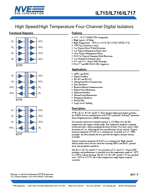
Package 0.3" SOIC 0.15" SOIC
UL 1577
Component Recognition Program File Number: E207481 Rated 2500VRMS for 1 minute
Soldering Profile
Per JEDEC J-STD-020C, MSL=2
TA TA VDD1, VDD2 VIH VIL tIR, tIF
Insulation Specifications
Parameters Creepage Distance
0.15" SOIC 0.3" SOIC Leakage Current Barrier Impedance
Symbol
Min. −55 −55 −0.5 −0.5 −0.5
Parameters Capacitance (Input–Output)(5) Thermal Resistance
0.15" SOIC 0.3" SOIC Package Power Dissipation
Symbol CI–O
θJC θJC
PPD
Min.
Typ.
4
41 28
Safety and Approvals
Typical transient immunity of 30 kV/µs is unsurpassed. High channel density makes these devices ideal for isolating ADCs and DACs, parallel buses and peripheral interfaces.
IsoLoop is a registered trademark of NVE Corporation. *U.S. Patent numbers 5,831,426; 6,300,617 and others.
TEA5767HN_中文数据手册

责任声明:1.该文章为在校研究生借助于谷歌翻译等工具自行翻译为中文资料,不代表官方意愿。
2.该文章只能用于学习交流之用,不可用于一切商业用途,否则后果自负,本作者不承担任何责任。
3.由于作者水平有限,难免有错误之处,此文章只做参考,以英文官方文献为准。
由于参考本文内容所造成的损失,后果自行承担。
4.如有侵权,请及时联系我删除。
QQ:782020255TEA5767HN一、一般说明TEA5767HN是一款单芯片电子调谐FM立体声收音机,适用于低压应用,具有完全集成的IF选择性和解调功能。
收音机完全无需调整,只需要最少的小型和低成本外部组件。
收音机可以调谐到欧洲,美国和日本FM频段。
二、特征1.集成低噪声RF输入放大器,灵敏度高2.用于转换为美国/欧洲(87.5MHz至108MHz)和日本(76MHz至91MHz)FM频段的IF的FM调音台3.预设调谐以接收高达108MHz的日本电视音频4.RF自动增益控制(AGC)电路5.LC调谐器振荡器采用低成本固定芯片电感器工作6.内部执行FM IF选择性7.由于完全集成的FM解调器,无需外部鉴别器8.晶体参考频率振荡器;振荡器以32.768kHz时钟工作9.晶体或13MHz晶体,外部施加6.5MHz参考频率10.PLL合成器调谐系统11.I2C总线和3线总线,可通过引脚BUSMODE选择12.通过总线输出7位IF计数器13.通过总线输出4位信息14.柔软的静音15.信号相关的单声道到立体声混合[立体声降噪(SNC)16.信号相关高切控制(HCC)17.可以通过总线关闭软静音,SNC和HCC18.免调整立体声解码器19.自主搜索调整功能20.待机模式21.两个软件可编程端口22.总线使能线将总线输入和输出线路切换为3态模式三、快速参考数据表1.快速参考数据V CCA=V CC(VCO)=V CCD;AC值以RMS给出;对于V RF,给出了EMF值;除非另有规定。
1SMA4749A中文资料
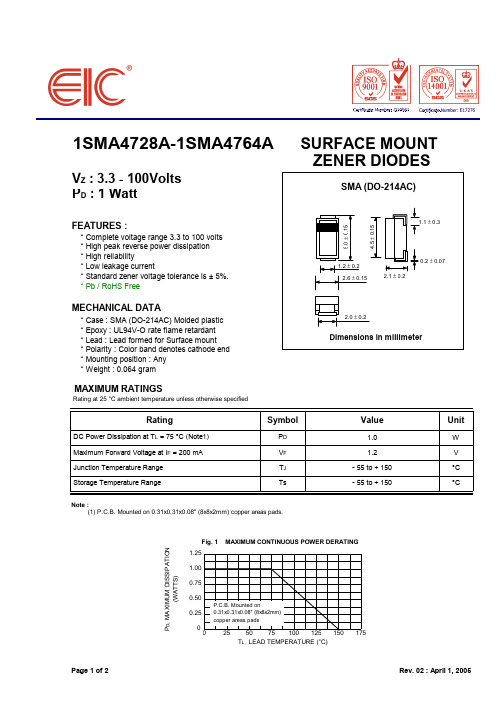
Rating at 25 °C ambient temperature unless otherwise specifiimum Zener Impedance IZK (mA) 1.0 1.0 1.0 1.0 1.0 1.0 1.0 1.0 1.0 0.5 0.5 0.5 0.25 0.25 0.25 0.25 0.25 0.25 0.25 0.25 0.25 0.25 0.25 0.25 0.25 0.25 0.25 0.25 0.25 0.25 0.25 0.25 0.25 0.25 0.25 0.25 0.25
元器件交易网
1SMA4728A-1SMA4764A
VZ : 3.3 - 100Volts PD : 1 Watt
FEATURES :
* Complete voltage range 3.3 to 100 volts * High peak reverse power dissipation * High reliability * Low leakage current * Standard zener voltage tolerance is ± 5%. * Pb / RoHS Free
SURFACE MOUNT ZENER DIODES
SMA (DO-214AC)
5.0 ± 0.15
4.5 ± 0.15
1.1 ± 0.3
1.2 ± 0.2 2.6 ± 0.15 2.1 ± 0.2
0.2 ± 0.07
MECHANICAL DATA
* Case : SMA (DO-214AC) Molded plastic * Epoxy : UL94V-O rate flame retardant * Lead : Lead formed for Surface mount * Polarity : Color band denotes cathode end * Mounting position : Any * Weight : 0.064 gram
AO4407A中文资料
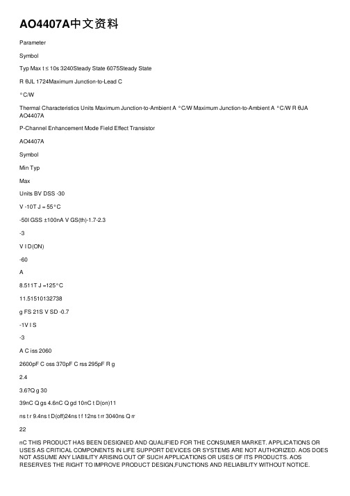
AO4407A中⽂资料ParameterSymbolTyp Max t ≤ 10s 3240Steady State 6075Steady StateR θJL 1724Maximum Junction-to-Lead C°C/WThermal Characteristics Units Maximum Junction-to-Ambient A °C/W Maximum Junction-to-Ambient A °C/W R θJAAO4407AP-Channel Enhancement Mode Field Effect TransistorAO4407ASymbolMin TypMaxUnits BV DSS -30V -10T J = 55°C-50I GSS ±100nA V GS(th)-1.7-2.3-3V I D(ON)-60A8.511T J =125°C11.51510132738g FS 21S V SD -0.7-1V I S-3A C iss 20602600pF C oss 370pF C rss 295pF R g2.43.6?Q g 3039nC Q gs 4.6nC Q gd 10nC t D(on)11ns t r 9.4ns t D(off)24ns t f 12ns t rr 3040ns Q rr22nC THIS PRODUCT HAS BEEN DESIGNED AND QUALIFIED FOR THE CONSUMER MARKET. APPLICATIONS OR USES AS CRITICAL COMPONENTS IN LIFE SUPPORT DEVICES OR SYSTEMS ARE NOT AUTHORIZED. AOS DOES NOT ASSUME ANY LIABILITY ARISING OUT OF SUCH APPLICATIONS OR USES OF ITS PRODUCTS. AOS RESERVES THE RIGHT TO IMPROVE PRODUCT DESIGN,FUNCTIONS AND RELIABILITY WITHOUT NOTICE.V GS =0V, V DS =-15V, f=1MHz Input Capacitance Output Capacitance Turn-On Rise Time Turn-Off DelayTime V GS =-10V, V DS =-15V, R L =1.25?, R GEN =3?Turn-Off Fall TimeTurn-On DelayTime m ?SWITCHING PARAMETERS Gate Source Charge Gate Drain Charge Total Gate Charge V GS =-10V, V DS =-15V, I D =-12ADYNAMIC PARAMETERS Maximum Body-Diode Continuous CurrentGate resistanceV GS =0V, V DS =0V, f=1MHzV GS = -5V, I D = -10AI S = -1A,V GS = 0V V DS = -5V, I D = -10AV GS = -10V, I D = -12A R DS(ON)Static Drain-Source On-ResistanceForward TransconductanceDiode Forward VoltageI DSS µA Gate Threshold Voltage V DS = V GS I D = -250µA V DS = -30V, V GS = 0VV DS = 0V, V GS = ±25V Zero Gate Voltage Drain Current Gate-Body leakage current Electrical Characteristics (T J =25°C unless otherwise noted)STATIC PARAMETERS Parameter ConditionsBody Diode Reverse Recovery TimeBody Diode Reverse Recovery Charge I F =-12A, dI/dt=100A/µsDrain-Source Breakdown Voltage On state drain currentI D = -250µA, V GS = 0V V GS = -10V, V DS = -5V V GS = -20V, I D = -12AReverse Transfer Capacitance I F =-12A, dI/dt=100A/µsA: The value of R θJA is measured with the device mounted on 1 in 2 FR-4 board with 2oz. Copper, in a still air environment with T A = 25°C. The value in any given application depends on the user's specific board design. The current rating is based on the t ≤ 10s thermal resistance rating.B: Repetitive rating, pulse width limited by junction temperature.C. The R θJA is the sum of the thermal impedence from junction to lead R θJL and lead to ambient.D. The static characteristics in Figures 1 to 6 are obtained using < 300µs pulses, duty cycle 0.5% max.E. These tests are performed with the device mounted on 1 in 2 FR-4 board with 2oz. Copper, in a still air environment with T A =25°C. The SOA curve provides a single pulse rating.F. The current rating is based on the t ≤ 10s thermal resistance rating.G. E AR and I AR ratings are based on low frequency and duty cycles to keep T j =25C.Rev3: Jan 2008AO4407AAO4407A。
1PH7电机参数
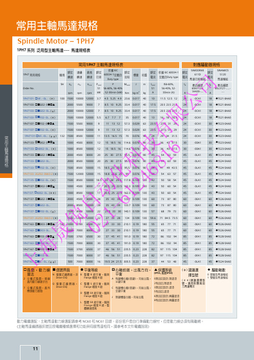
1PH7133- £ND02- 0L.. (*)
1000 8500 10000 12 15 18.5 16 114.6 0.076 90 30 36 43 37.5 30
技 6 1PH7133- £¢G02- 0ò§p
2000 4500 8000 20 25 30 27.5 95.5 0.076 90 45 54 63 59
60
自 - 1PH7137- £¢F02- 0L.. (*)
1500 8500 10000 22 27.5 33 30 140.1 0.109 130 57 68 79 73
60
1PH7137- 2GZ02- 0MJ3-Z (*)
1500 12000 12000 22 27 33 28 134 0.109 130 59.6 71 84.5 73.5 60
ø 驅動軸數
0 單軸型馬達模組 1 雙軸型馬達模組
動力電纜選配:主軸馬達動力線選配請參考 NC60 和 NC61 目錄。部份客戶是自行準備動力線材,但是動力線必須有隔離網。 (主軸馬達編碼器訊號回授電纜種類選擇和功能與伺服馬達相同,請參考本文件電纜說明)
11
常用伺服馬達規格
Servo Motor –1FK7 Compact
1 1PH7163- £¢D03- 0ò§p 160 1000 3700 6500 22 27 33 30 210.1 0.19 180 55 65 77 71
60
锐 2 1PH7163- £¢D03- 0L..
1000 7000 8000 22 27 33 30 210.1 0.19 180 55 65 77 71
電流 定義的Duty type
SIMODRIVE
額定
LT3757

LT3757 / LT3757A特征·输入电压范围宽:2.9 v至40 v·正面或负面输出电压编程用一个反馈销·提供了出色的瞬态电流模式控制响应可编程操作频率(100 khz与一个外部电阻1 mhz) ·Synchronizable外部时钟当前< 1µa·低关闭·内部7.2 v回动电压调整器·可编程软启动·小10-Lead DFN(3毫米×3毫米)和热增强10-Pin MSOP包描应用·汽车和工业,回程,SEPIC和反相转换器·电信电力供应·便携式电子设备描述LT®3757 / LT3757A宽输入范围内,电流模式DC / DC控制器,能够产生正相或负相的输出电压。
他们既可以配置为提振,回程,SEPIC或反相转换器。
LT3757 / LT3757A驱动外部权力N-chanel MOSFET低端从内部监管7.2 v供应。
固定频率,电流型架构使其能稳定运行在大频带供应和输出电压。
LT3757 / LT3757A的工作频率可以设置与外部电阻器在100千赫至1 MHz范围,并且可以使用接口与外部时钟同步。
较低的最小操作电源电压为2.9 v,关闭和低静态电流小于1µa,使LT3757 / LT3757A适合电池供电的系统。
LT3757 / LT3757A软启动和频率特性在启动监听功能限制电感电流和输出短路。
LT3757A改善了负载瞬态性能可与LT3757相比。
典型应用高效升压斩波器效能绝对最大额定参数(Note 1)工作温度范围储存温度范围焊接温度范围引脚结构指令信息咨询LTC营销部分指定的工作温度范围较宽。
*温度等级确定集装箱上的一个标签。
在无铅标识部分的更多信息,去:/leadfree/在磁带和卷轴规范的更多信息,去:/tapeandreel/电气特性l表示规格适用于完整的操作温度范围,否则规范TA = 25°C。
LT1117 中文资料
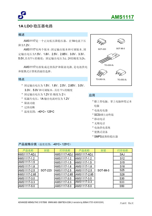
0.5
%
Tamb=125°C, 1000Hrs
0. 3
%
% of VOUT, 10Hz≤f≤10kHz
0.003
%
SOT-223-3
120
TO-252-2
100
θJA TO-263-3
60
°C/W
SOT-89-3
165
TO-220-3
60
ADVANCED MONOLITHIC SYSTEMS (translate by BONA 0755-82800289)
IOUT=10mA, VIN=3.8V, TJ=25°C , 1.782 1.800 1.818 V
0≤IOUT≤1A, 3.2V≤VIN≤10V
1.764 1.800 1.836
AMS1117-2.5,
IOUT=10mA, VIN=4.5V,TJ=25°C , 2.475 2.500 2.525 V
VREF IOUT=10mA, VIN-VOUT=2V, TJ=25°C 1.238 1.250 1.262 V 10mA≤IOUT≤1A, 1.4V≤VIN-VOUT≤10V 1.225 1.250 1.270
AMS1117-1.2,
IOUT=10mΑ, VIN=3.2V ,TJ=25°C 10mA≤IOUT≤1A, 3.0V≤VIN≤10V
0≤ IOUT≤1A, 6.5V≤VIN≤12V
4.900 5.000 5.10
TSOUT
Rline
VINMIN ≤VIN≤ 12V, VOUT=Fixed/Adj,
IOUT=10mA
0.3
%
3
7 mV
Rload Vdrop
Iq
10mA≤IOUT≤ 1A,VOUT=Fixed/Adj IOUT=100mA IOUT=500mA IOUT=1A 4.25V≤VIN≤ 6.5V
A1117A

THERMAL PROTECTION AND 1.2A CURRENT LIMIT DESCRIPTION FEATURESThe A1117A is a series of low dropout three-terminal regulators with a dropout of 1.26V at 1A load current.The A1117A series of positive fixed voltage (V OUT = 1.2V, 1.8V, 2.5V, 2.8V, 3.3V, 5V) and adjustable version, which can provide an output voltage from 1.25V to 13.8V with only two external resistors.The A1117A offers current limiting and thermal protection to assure the stability of chip and power system.The A1117A is available in SOT-223, SOT-89-3 and TO-252 Package. ●Output Current of 1A Maximum●Three-Terminal Adjustable or Fixed Outputs●Maximum Input Voltage: 15V●Fast Transient Response●Current Limit, Safe Operating and ThermalShutdown Protection●Line Regulation: 0.2%●Load Regulation: 0.4%●Environment Temperature: -40o C~+85o C●Available in SOT-223, SOT-89-3, TO-252PackageAPPLICATION●High Efficiency Linear Regulators●Post Regulator for Switching DC/DC Converter ●Power Management for M/B and Graphic Card● 2.85V Model for SCSI-2 Active Termination●Battery Charger●LCD Monitor and LCD TV●DVD Decode Board●ADSL ModemTYPICAL APPLICATION (Schematic 1)Adjustable Output VersionV OUT=V REF(1+R2/R1)+I ADJ*R2The output of A1117A-ADJ provides any output voltage between1.25V~13.8V can be available by choosing two external resistors.Fixed Output VersionORDERING INFORMATIONTHERMAL PROTECTION AND 1.2A CURRENT LIMITPIN DESCIPTIONABSOLUTE MAXIMUM RATINGS Stresses above may cause permanent damage to the device. These are stress ratings only, and functional operation of the device at these or any other conditions beyond those indicated in the Electrical Characteristics is not implied. Exposure to absolute maximum rating conditions for extended periods may affect device reliability.RECOMMENDED WORKING CONDITIONSTHERMAL PROTECTION AND 1.2A CURRENT LIMIT ELECTRICAL CHARACTERISTICSTest Condition: V IN = V OUT +2V, I O =10mA, and T J = 25o C, unless otherwise specified.THERMAL PROTECTION AND 1.2A CURRENT LIMIT Conti…Note 1:The Parameters of Line Regulation and Load Regulation are tested under constant junction temperature. The Curve of Load Regulation vs. Temperature is shown in typical parameter curve that follows.Note 2:When I OUT varies between 0~1A,V IN-V OUT varies between 1.5V~12V under constant junction temperature,the parameter is satisfied the criterion as above mentioned. If temperature varies between -50°C≦T A≦140°C,it needs output current to be larger than 10mA to satisfy the criterion.Note 3:Dropout Voltage is specified over the full output current range of the device, and it is tested under following testing conditions: First step is to find out the V OUT value (V OUT1) when V IN1=V OUT+1.5V,Second step is to decrease V IN (V IN2) until V OUT value is equal to 98.5%*V OUT1(V OUT2). V DROPOUT=V IN2-V OUT2.Note 4:Minimum Load Current is defined as the minimum output current required to maintain regulation.When 1.5V≦V IN-V OUT≦12V,the device is guaranteed to regulate if the output current is greater than 10mA.THERMAL PROTECTION AND 1.2A CURRENT LIMIT TYPICAL PERFORMANCE CHARACTERISTICS1.Load Regulation (V OUT=3.3V)2.Load Regulation vs. Temperature(I OUT form 10mA to 1A)3.Line Regulation(V OUT=3.3V, I OUT=10mA) 4.Dropout Voltage (T A=25o C, 90o C)5.Output Voltage vs. TemperatureV OUT=3.3V6.Output Voltage vs. TemperatureTHERMAL PROTECTION AND 1.2A CURRENT LIMIT 7.Adjustable Pin Current vs. Temperature 8.Load Transient Response(Load Current Change from 2mA to 500mA)THERMAL PROTECTION AND 1.2A CURRENT LIMIT BLOCK DIAGRAMTHERMAL PROTECTION AND 1.2A CURRENT LIMIT DETAILED INFORMATIONThe A1117A is a series of low dropout voltage, three terminal regulators. The A1117A’s application circuit is very simple: the fixed version only needs two capacitors and the adjustable version only needs two resistors and two capacitors to work. The A1117A is composed of some modules including start-up circuit, bias circuit, band-gap, thermal shutdown, current limit, power transistors and A1117A’s driver circuit etc.Thermal ShutdownThe thermal shutdown and current limit modules can assure chip and its application system working safety when the junction temperature is larger than 140o C or output current is larger than 1.2A.Band-gap ModuleThe band-gap module provides stable reference voltage, whose temperature coefficient is compensated by careful design considerations. The temperature coefficient is under 100ppm/o C. And the accuracy of output voltage is guaranteed by trimming technique.Application Hints:1. Recommend using 10uF tan capacitor (C IN) as bypass capacitor for all application circuit.2. Recommend using 22uF tan capacitor (C OUT) to assure circuit stability.3. Using a bypass capacitor (C ADJ) between the adjust terminal and ground can improve ripple rejection. This bypass capacitor prevents ripple from being amplified as the output voltage is increased. The impedance of C ADJ should be less than the resistor’s (R1) which is between output and adjust pins to prevent ripple from being amplified at any ripple frequ ency. As R1 is normally in the range of 200Ω~350Ω,the value of C ADJ should satisfy this equation: 2*Fripple* C ADJ<R1. Recommend using 10uF tan capacitor.Adjustable Output VersionA1117A has adjustable & fixed output version, Fig 1. is typical adjustable output version application. The A1117A adjustable version provides 1.25V reference voltage. Any output voltage between 1.25V~13.8V can be available by choosing two external resistors (R1 & R2, connection method is showed in Fig 1.)THERMAL PROTECTION AND 1.2A CURRENT LIMITFig1. Adjustable Output VersionThe output voltage of adjustable version satisfies this followed equation:V OUT=V REF*(1+R2/R1) + I ADJ*R2.We can ignore I ADJ because I ADJ (about 50uA) is much less than the current of R1 (about 4mA).The value of R1 should be in the range of 200Ω~350Ω to assure chip working normally without any load. To assure the electrical performance, the output current should be larger than 5mA. If R1 is too large, the minimum output current should be larger than 4mA. The best working condition is to assure that the output current exceeds 10mA.Fixed Output VersionThe A1117A typical circuit of fixed output version showed in Fig 2.Fig 2. Fixed Output Voltage VersionThermal ConsiderationHeat dissipation should be considered when output current or differential voltage of input and output voltage is large. In such case, the power dissipation consumed by A1117A is very large. The A1117A series uses SOT-223 package type and its thermal resistance is about 20o C/W. And the copper area of application board can affect the total thermal resistance. If copper area is 5cm & 5cm (two sides), the resistance is about 30o C/W. So total thermal resistance is about 20o C/W + 30o C/W. It can be decreased total thermal resistance by increasing copper area in application board.THERMAL PROTECTION AND 1.2A CURRENT LIMITPACKAGE INFORMATIONDimension in SOT-223 (Unit: mm)Tape DimensionReel DimensionTHERMAL PROTECTION AND 1.2A CURRENT LIMITDimension in SOT-89-3 (Unit: mm)Tape Dimension Reel DimensionTHERMAL PROTECTION AND 1.2A CURRENT LIMITDimension in TO-252 (Unit: mm)Tape Dimension Reel DimensionTHERMAL PROTECTION AND 1.2A CURRENT LIMIT IMPORTANT NOTICEAiT Semiconductor Inc. (AiT) reserves the right to make changes to any its product, specifications, to discontinue any integrated circuit product or service without notice, and advises its customers to obtain the latest version of relevant information to verify, before placing orders, that the information being relied on is current.AiT Semiconductor Inc.'s integrated circuit products are not designed, intended, authorized, or warranted to be suitable for use in life support applications, devices or systems or other critical applications. Use of AiT products in such applications is understood to be fully at the risk of the customer. As used herein may involve potential risks of death, personal injury, or servere property, or environmental damage. In order to minimize risks associated with the customer's applications, the customer should provide adequate design and operating safeguards.AiT Semiconductor Inc. assumes to no liability to customer product design or application support. AiT warrants the performance of its products of the specifications applicable at the time of sale.。
LT70-868终端用户指南说明书

1VV0301096 Rev.0 – 24/10/2013
This document is related to the following product: PRODUCT LT70-868 Terminal
LT70-868 Terminal User Guide 1VV0301096 Rev.0 – 24/10/2013
Telit disclaims any and all responsibility for the application of the devices characterized in this document, and notes that the application of the device must comply with the safety standards of the applicable country, and where applicable, with the relevant wiring rules.
Copyright: Transmittal, reproduction, dissemination and/or editing of this document as well as utilization of its contents and communication thereof to others without express authorization are prohibited. Offenders will be held liable for payment of damages. All rights are reserved.
The information contained in this document is the proprietary information of Telit Communications S.p.A. and its affiliates (“TELIT”). The contents are confidential and any disclosure to persons other than the officers, employees, agents or subcontractors of the owner or licensee of this document, without the prior written consent of Telit, is strictly prohibited.
Agilent HLMP-CW70、HLMP-CW72 T-1 3 4精密光学性能白LED数据手册说
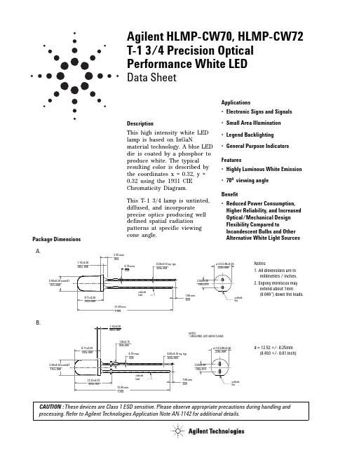
CAUTION : These devices are Class 1 ESD sensitive. Please observe appropriate precautions during handling and processing. Refer to Agilent Technologies Application Note AN-1142 for additional details.Agilent HLMP-CW70, HLMP-CW72T-1 3/4 Precision Optical Performance White LEDData SheetDescriptionThis high intensity white LED lam p is based on InGaNmaterial technology. A blue LED die is coated by a phosphor to produce white. The typical resulting color is described by the coordinates x = 0.32, y = 0.32 using the 1931 CIE Chrom aticity Diagram.This T-1 3/4 lam p is untinted, diffused, and incorporate precise optics producing well defined spatial radiation patterns at specific viewing cone angle.Applications•Electronic Signs and Signals•Small Area Illumination •Legend Backlighting •General Purpose Indicators Features•Highly Luminous White Emission •70o viewing angle Benefit•Reduced Power Consumption, Higher Reliability, and Increased Optical/Mechanical Design Flexibility Compared toIncandescent Bulbs and Other Alternative White Light SourcesPackage Dimensions A.Notes:1. All dimensions are in millimeters / inches.2. Expoxy meniscus may extend about 1mm(0.040”) down the leads.B.d = 12.52 +/- 0.25mm (0.493 +/- 0.01 inch)2Device Selection Guide Absolute Maximum Ratings (T A = 25°C)Electrical Characteristics (T A = 25°C)Optical Characteristics (T A = 25°C)Notes:1.The chromaticity coordinates are derived from the CIE 1931 Chromaticity Diagram and represent the perceived color of the device.2.θ1/2 is the off-axis angle where the luminous intensity is ½ the peak intensity.Part Number Min Luminous Intensity Iv (mcd) @ 20mA Max Luminous IntensityIv (mcd) @ 20mA Standoff OptionPackage Dimension HLMP-CW70-K00xx 310-No A HLMP-CW70-LP0xx 4001150No A HLMP-CW72-LP0xx4001150YesBTolerance for intensity limit is +/- 15%ParameterValue Units DC Forward Current [1]30mA Peak Forward Current [2]100mA Power Dissipation 120mW Reverse Voltage (I R = 10µA)5V LED Junction Temperature 110°C Operating Temperature Range -40 to +85°C Storage Temperature Range -40 to +100°C Dip-Drag Solder Temperature [3]260 for 5 secs °C Wave Solder Temperature [3]245 for 3 secs°CNotes:1.Derate linearly as shown in Figure 5.2.Duty factor 10%, 1 KHz.3. 1.59mm (0.062 inch) below seating plane.Forward Voltage,V F (V) @ I F = 20 mA Reverse Breakdown, V R (V) @ I R = 10µA Capacitance, C (pF), V F = 0,f = 1 MHz Thermal Resistance R θJ-PIN (°C/W)Typ.Max.Min.Typ.Typ.3.64.0570240Typical Chromaticity Coordinates[1]Viewing Angle 2θ1/2Degrees[2] Typ.X y 0.320.32703Figure 1. Relative Intensity vs WavelengthFigure 2. Forward Current vs Forward VoltageFigure 3. Relative Iv vs. Forward CurrentFigure 4. X,Y Coordinates vs Forward CurrentFigure 5. Maximum Fwd. Current vs TemperatureFigure 6. Spatial Radiation Pattern/semiconductorsFor product information and a complete list of distributors, please go to our web site.Data subject to change.Copyright 2003 Agilent Technologies, Inc.January 19, 20045989-0457ENIntensity Bin Limits (mcd at 20 mA)Color Bin Limit Tables。
Panasonic FP7 AFP7CPS41E CPU 单元说明书
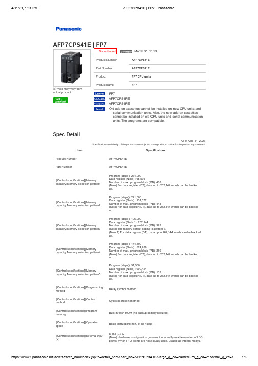
※Photo may vary fromactual product.Product Number AFP7CPS41EPart Number AFP7CPS41EProduct FP7 CPU unitsProduct nameFP7Spec DetailAs of April 11, 2023Specifications and design of the products are subject to change without notice for the product improvement.Item SpecificationsProduct Number AFP7CPS41EPart Number AFP7CPS41E[[Control specifications]]Memory capacity:Memory selection pattern1Program (steps): 234,000Data register (Note) : 65,536Number of max. program block (PB): 468(Note) For data register (DT), data up to 262,144 words can be backedup.[[Control specifications]]Memory capacity:Memory selection pattern2Program (steps): 221,500Data register (Note) : 131,072Number of max. program block (PB): 443(Note) For data register (DT), data up to 262,144 words can be backedup.[[Control specifications]]Memory capacity:Memory selection pattern3Program (steps): 196,000Data register (Note 1): 262,144Number of max. program block (PB): 392(Note) The factory default setting is pattern 3.(Note 1) For data register (DT), data up to 262,144 words can be backedup.[[Control specifications]]Memory capacity:Memory selection pattern4Program (steps): 144,500Data register (Note) : 524,288Number of max. program block (PB): 289(Note) For data register (DT), data up to 262,144 words can be backedup.[[Control specifications]]Memory capacity:Memory selection pattern5Program (steps): 51,500Data register (Note) : 999,424Number of max. program block (PB): 103(Note) For data register (DT), data up to 262,144 words can be backedup.[[Control specifications]]Programmingmethod Relay symbol method[[Control specifications]]Controlmethod Cyclic operation method[[Control specifications]]Programmemory Built-in flash ROM (no backup battery required)[[Control specifications]]Operationspeed Basic instruction: min. 11 ns / step[[Control specifications]]External input (X)8,192 points(Note) Hardware configuration governs the actually usable number of I / Opoints. When I / O points are not actually used, usable as internal relays.March 31, 2023FP7AFP7CPS4REAFP7CPS4REOld add-on cassettes cannot be installed on new CPU units andserial communication units. Also, the new add-on cassettescannot be installed on old CPU units and serial communicationunits. The programs are compatible.[[Control specifications]]External output (Y)8,192 points(Note) Hardware configuration governs the actually usable number of I / O points. When I / O points are not actually used, usable as internal relays.[[Control specifications]]Internal relay(R)32,768 points[[Control specifications]]System relay(SR)Indicate operation status of various relays is shown. [[Control specifications]]Link relay (L)16,384 points[[Control specifications]]Timer (T)4,096 points: Timer capable of counting (units: 10 micro s, 1 ms, 10 ms, 100 ms or 1 sec.) x 4,294,967,295[[Control specifications]]Counter (C)1,024 points, Counter capable of counting 1 to 4,294,967,295 [[Control specifications]]Link dataregister (LD)16,384 words[[Control specifications]]System dataregister (SD)Internal operation status of various registers is shown.[[Control specifications]]Index register(I0 to IE)15 long words / With switching function[[Control specifications]]Mastercontrol relay (MCR)Unlimited[[Control specifications]]Number oflabels (LOOP)Max. 65,535 points for each program block (PB)[[Control specifications]]DifferentialpointsUnlimited[[Control specifications]]Number ofstep laddersUnlimited[[Control specifications]]Number ofsubroutinesMax. 65,535 points for each program block (PB)[[Control specifications]]Number ofinterrupt program1 periodical interrupt program[[Control specifications]]SD memorycard functionSDHC memory cards of up to 32 GB are usable.[[Control specifications]]ConstantscanAvailable (0 to 125 ms)[[Control specifications]]Clock / calendar Year (last two digits), month, day, hours (24-hour display) minutes, seconds, day of week(Note)Precision of calendar; At 0 ℃+32 ℉, 95 sec. or less error per month, at +25 ℃+77 ℉, 15 sec. or less error per month, at +55 ℃+131℉, 130 sec. or less error per month[[Control specifications]]Battery life (Value applies when no power is supplied at all.)3.3 years or more (when no power is supplied) actual usage value: 20 years approx. (at 25 degrees 77 degrees Fahrenheit )[[Control specifications]]SafetyfunctionPassword / Restricted distribution / Read disable setting / Encryption[[Control specifications]]PLC link function(Serial communication / MEWNET-W0)Max. 16 units, link relays: 1,024 points, link registers: 128 words. (Data transfer and remote programming are not supported) (Link area allocation is switchable between the first and the second half)[[Communication specifications for COM port]]Interface RS-232C, three-wire system, 1 channel(Note) SD, RD and SG terminals are isolated from internal circuits.[[Communication specifications forCOM port]]Transmission distance15 m 49.213 ft[[Communication specifications for COM port]]Transmission speed 300, 600, 1200, 2400, 4800, 9600, 19200, 38400, 57600, 115200, 230400 bits / sec,[[Communication specifications forCOM port]]Communication methodHalf-duplex system[[Communication specifications forCOM port]]Synchronous methodStart-stop synchronization system[[Communication specifications for COM port]]Transmission format Stop bit: 1 bit / 2 bits Parity: none / odd / even Data length: 7 bits / 8 bitsStart code: with STX / without STXEnd code: CR / CR + LF / none / ETX[[Communication specifications forCOM port]]Data transmission orderTransmit from bit 0 in character units.[[Communication specifications forCOM port]]ConnectionGeneral-purpose communication, Computer link and MODBUS-RTU[[Dedicated power supply output port specifications for GT series programmable display]]Terminal:5V For 5 V DC type GT series Programmable Display(Note) 5 V and 24 V DC types are not usable at the same time.[[Dedicated power supply output port specifications for GT series programmable display]]Terminal:24V For 24 V DC type GT series Programmable Display(Note 1) 5 V and 24 V DC types are not usable at the same time. (Note 2) Use 21.6 to 26.4 V DC to power the CPU unit. Please check the “GT Series Hardware Manual” for grounding of the GT series programmable display.[[LAN communication portspecifications]]CommunicationinterfaceEthernet 100BASE-TX / 10BASE-TX[[LAN communication portspecifications]]Communication speed100 Mbps, 10 Mbps auto negotiation function[[LAN communication portspecifications]]Total cable length100 m 328 ft (500 m 1,640 ft when a repeater is used)[[LAN communication portspecifications]]Number of nodesMax. 254 units[[LAN communication portspecifications]]Number ofsimultaneous connectionsMax. 220 connections (user connection: 216, system connection: 4)[[LAN communication portspecifications]]Communicationprotocol (Communication layer)TCP / IP, UDP[[LAN communication portspecifications]]DNSSupports name servers[[LAN communication portspecifications]]DHCP / DHCPV6Automatic IP address acquisition[[LAN communication port specifications]]FTP server / Client (SSL compatible)Server function, file transfer, number of user: 3 Client function, data and file transfer[[LAN communication port specifications]]HTTP server / Client (SSL compatible)Server function, system web, Customer web (8 MB), number of concurrent session: 16Client function, data transfer[[LAN communication portspecifications]]SMTP client (SSLcompatible)Client function, mail transfer[[LAN communication portspecifications]]SNTPTime adjustment function[[LAN communication portspecifications]]General-purposecommunication16 kB / 1 connection (user connection: 1 to 16)[[LAN communication port specifications]]Dedicated communication Slave communication (MEWTOCOL-COM, MEWTOCOL7-COM, MEWTOCOL-DAT, MODBUS-TCP, MC protocol (Note))Master communication (MEWTOCOL-COM, MEWTOCOL-DAT, MODBUS-TCP, MC protocol (Note))(Note): MC protocol is a short form denoting MELSEC communication protocol; MELSEC is a registered trademark of Mitsubishi Electric Corporation. QnA compatible 3E frame, only binary (bulk writing and bulk reading) use is available.[[Common generalspecifications]]Ambient temperature0 to +55 ℃+32 to +131 ℉, Storage: -40 to +70 ℃-40 to +158 ℉[[Common general specifications]]Ambient humidity 10 to 95 % RH (at +25 ℃+77 ℉, no condensation), Storage: 10 to 95 % RH (at +25 ℃+77 ℉, no condensation)[[Common general specifications]]Vibration resistance 5 to 8.4 Hz, single amplitude of 3.5 mm 0.138 in, 1 sweep/min. (IEC 61131-2) ; 8.4 to 150 Hz, constant acceleration of 9.8 m/s2, 1 sweep/min. (IEC 61131-2), 10 times each in X, Y, and Z directions[[Common generalspecifications]]Shock resistance147 m/s2 or more ,3 times each in X, Y, and Z directions (IEC61131-2) [[Common general1,000 V [p-p] with pulse width 50 ns and 1 micro s (using a noiseProduct Number Part NumberProduct Details Product nameProduct Number Part NumberProduct Details Product name Product Number Part Number ProductProduct Number Part Number Product Product Number Part NumberProductProduct namespecifications]]Noise immunity simulator)[[Common generalspecifications]]Operating conditionFree from corrosive gasses and excessive dust[[Individual generalspecifications]]Rated voltage range20.4 to 28.8 V DC[[Individual generalspecifications]]Current consumption200 mA or less[[Individual general specifications]]Netweight220 g approx. (with terminal block and end unit) AccessoriesProduct Number Part Number Product Product name Product Number Part Number Product Details Product name ProductNumber Part Number Product Details Product name ProductNumber Part Number Product Details Product name ProductNumber Part Number Product Product name ProductNumber Part Number Product Product name ProductNumber Part Number Product Product name ProductNumber Part Number Product Product name ProductNumber Part Number Product Product name ProductNumber Part Number Product Product name ProductNumber Part Number Product Details Product name ProductNumber Part Number Product Product nameProduct Number Part Number Product Product name Product Number Part Number Product Product name ProductNumber Part Number Product Product nameProductNumberAFP7PSA1 Part Number AFP7PSA1Product FP7 Power supply unitsProduct name FP7 Power supplyunitsProductNumberAFP7PSA2Part Number AFP7PSA2ProductFP7 Power supplyunitsProductnameFP7 Power supplyunitsProductNumberAFP7RTD8Part Number AFP7RTD8ProductFP7 Temperatureinput unitsProductnameFP7 Temperatureinput unitsProduct Number Part NumberProductProduct name ProductNumberPart NumberProductDetailsProductnameProductNumberPart NumberProductDetailsProductnameProduct Number Part NumberProductDetails Product name ProductNumberPart NumberProductDetailsProductnameProductNumberPart NumberProductDetailsProductnameProduct Number Part NumberProductDetails Product name ProductNumberPart NumberProductDetailsProductnameProductNumberPart NumberProductDetailsProductnameProduct Number Part NumberProductDetails Product name ProductNumberPart NumberProductDetailsProductnameProductNumberPart NumberProductDetailsProductnameDiscontinued Discontinued DiscontinuedProductNumberAFP8503 Part Number AFP8503Product name Motor Driver I/FTerminal IIProductNumberAFP8504Part Number AFP8504ProductnameMotor Driver I/FTerminal IIProductNumberAFP85100Part Number AFP85100ProductnameConnection cablefor PosiotioningunitProduct Number Part NumberProductDetails Product name ProductNumberPart NumberProductDetailsProductnameProductNumberPart NumberProductDetailsProductnameProduct Number Part NumberProductDetails Product name ProductNumberPart NumberProductDetailsProductnameProductNumberPart NumberProductDetailsProductnameProduct Number Part NumberProductDetails Product nameDiscontinuedProductNumberPart NumberProductDetailsProductnameProductNumberPart NumberProductDetailsProductnameProduct Number Part Number ProductNumberPart NumberProductNumberPart NumberProduct name Control FPWINGR7ProductnameControl FPWINGR7ProductnameControl FPWINGR7Product Number Part NumberProductProduct name Product Number Part NumberProductProduct nameProduct Number Part NumberProduct Details Product name Product Number Part NumberProduct name© Panasonic Industry Co., Ltd.。
- 1、下载文档前请自行甄别文档内容的完整性,平台不提供额外的编辑、内容补充、找答案等附加服务。
- 2、"仅部分预览"的文档,不可在线预览部分如存在完整性等问题,可反馈申请退款(可完整预览的文档不适用该条件!)。
- 3、如文档侵犯您的权益,请联系客服反馈,我们会尽快为您处理(人工客服工作时间:9:00-18:30)。
(Internet)
As of January 1997 Tec.L970102-A
LT1E77A
High-luminosity, Super Compact Chip LED Device
General Description Sharp's LT1E77A(high-luminosity, yellow-green) is thin type super compact size chip LED device.(1.6 x 0.8 x 0.5mm) It is suitable for backlight of portable equipment such as cellular phone and pager etc. Features (1) Thin type( Thickness: 0.5mm) (2) Super compact size(1.6 x 0.8 x 0.5mm) (3) Realizes high-luminosity due to originally developed PWB with reflector (4) Tape packaged product( 5 000pcs./reel) Applications (1) Cellular phones (2) Pagers (3) Other portable equipment (4) Various compact equipment that requires high-density mouting
(Ta=25˚C) Unit mW mA mA mA/˚C V ˚C ˚C (Ta=25˚C) Unit V mcd nm nm µA pF
*1 Duty ratio=1/10 Pulse width=0.1ms
Reverse voltage Operating temperature Storage temperature Parameter Forward voltage *2 Luminous intensity Peak emission wavelength Spectrum radiation bandwidth Reverse current Terminal capacitance Symbol VF IV λP ∆λ IR Ct
Electro-optical Characteristics
Condition
IF=20mA
VR=4V V=0V, f=1MHz
*2 Measured by Sharp by EG & G MODEL550 (RADIOMETER/PHOTOMETER SYSTEM)
(Notice)
• In the absence of device specification sheets, SHARP takes no responsibility for any defects that may occur in equipment using any SHARP devices shown in catalogs, data books, etc. Contact SHARP in order to obtain the latest device specification sheets before using any SHARP device. • Specifications are subject to change without notice for improvement. • Data for Sharp's optoelectronic/power devices is provided for internet. ( Address http://www.sharp.co.jp/ecg/)
0.21 0.8
Chiions
1.6 (0.2)
(Unit:mm)
0.5
1 1.2 1.0
2 Emitter center
* Plating area * Terminal connection
1 Cathode 2 Anode
1
2
Absolute Maximum Ratings
