CJ6B电动机构使用说明书
CJ6型系列电动机操动机构说明书

CJ6型系列电动机操动机构产品安装使用说明书上海输配电气有限公司CJ6型系列电动机操动机构产品安装使用说明书一、概述CJ6型电动机构系AC380V、AC220V、DC110V异步电动机驱动,通过齿轮及涡轮减速的操动机构。
它主要用来操作500千伏及以下湖外高压隔离开关。
CJ6型电动机构配有手柄,可以在现场进行手动操作。
本产品使用条件:(1)环境温度不高于+40℃,不低于-30℃。
(2)相对湿度不大于90%(+25℃时)。
(3)地震烈度不大于8度(4)不能使用在有严重化学腐蚀、盐雾、可燃性气体及强烈震动等地区。
(5)不能用于非水平安装场所。
表1 CJ6型电动机机构技术数据二、结构及工作原理CJ6型电动机机构系电动机驱动,通过一套机械减速装置将力矩传递给机构主轴,安装时借助于钢管连接使隔离开关主闸刀或接地刀分合闸。
电动机机构由电动机、机械减速传动系统、电气控制系统及箱壳组成。
电动机为三相交流异步电动机,机械减速传动系统包括齿轮、蜗杆、蜗轮及输出转轴。
蜗杆端部为方轴、可装手动摇柄进行手动操作。
电气控制部分包括电源转换开关、控制按钮(分、合、停各一个)、交流接触器、行程开关、热继电器及辅助开关等。
箱壳由钢板制成,起支撑及保护作用,为便于安装及检修,在正面和侧面各有一门。
通过电气控制系统控制电动机,电动机通过两对齿轮传递给蜗杆-蜗轮,带动输出主轴。
减速系统为三次减速,地一二次为齿轮减速,第三次是蜗杆蜗轮减速。
齿轮减速使用规格不同的齿轮可组成两种传动比,故使总的传动比也有两种,第一种使电动机机构分闸或合闸一次动作时间为7.5秒。
第二中使电动机机构分闸或合闸一次动作时间为3秒。
电气控制原理见图3,机构分、合闸按钮(或远方控制)控制接触器,接触器控制电动机,终止位置靠行程开关切断控制电路。
“停”按钮供异常情况时紧急停止使用。
电动机机构动作程序如下:先关合电源转换开关接通电源,分闸时手按分闸按钮(或远距离按钮)将分闸用交流接触器的控制线圈接通,接触器常开触头闭合,使三相交流电接通,电动机向分闸方向旋转,通过二级齿轮减速,再经蜗杆、蜗轮减速后将力矩传送给机构主轴,使主轴旋转180度。
[整理]ZGKC-6B高压开关动特性测试仪说明书.
![[整理]ZGKC-6B高压开关动特性测试仪说明书.](https://img.taocdn.com/s3/m/092a74a89ec3d5bbfd0a749b.png)
ZGKC-6B高压开关动特性测试仪使用手册武汉智能星电气有限公司2012-2-20目录一、概述 (3)二、特点及主要功能 (3)三、技术指标 (5)1.主要技术参数 (5)2.常规试验测试 (6)3.重合闸试验测试 (7)4.低电压试验测试 (8)五、接线方式介绍 (10)1.断口接线说明 (10)2.速度传感器安装说明 (11)3.控制线接线说明 (12)六、速度定义说明 (15)1.几种基本的速度定义方式 (15)2.几种常用开关的速度定义 (15)七、仪器软件操作说明 (19)1.主界面介绍 (19)2.常规试验操作 (19)3.重合闸试验操作 (24)4.低电压试验操作 (26)5.历史数据管理 (29)6.系统参数设置 (31)八、上位机软件操作说明 (33)1. 软件安装 (33)2. 打开软件 (34)3. 联机操作 (34)4. 导入数据 (37)5. 分析数据 (37)6. 发布数据 (39)九、测试过程中常见问题 (40)八、注意事项 (43)九、运输、贮存 (43)十、售后服务 (44)ZGKC-6B 高压开关动特性测试仪一、概述高压断路器是电力系统中最重要的控制设备之一。
电网中高压断路器的运行数量最多,运行条件和技术要求比较复杂,其运行可靠性不仅关系到高压断路器本身,而且影响到其它设备乃至整个电网。
因此,对高压断路器的动特性进行测试是一项很重要的工作,但采用传统的方法对高压断路器进行动特性测试时存在操作复杂、测试精度低等缺点,为了解决这些问题,我们开发了ZGKC-6B高压开关动特性测试仪。
二、特点及主要功能1. 10寸平板电脑远程同步界面控制配置10寸1024×768平板电脑(可选配其它笔记本),Windows XP/Windows 7操作系统,通过USB转RS232接口同步仪器界面,远程进行操作控制仪器、可导出试验数据;2. 超大水晶触摸彩屏、高速热敏打印机5.7寸640×480彩色触摸屏,人性化交互式水晶界面,图文显示,界面直观,便于现场人员操作和使用;高速热敏打印机,方便现场打印试验数据和曲线;3. 集成超强性能直流电源集成操作电源,无须现场二次电源,现场使用更加方便快捷;电源电压30V~300V可调,电流20A,连续工作时间3s;4.三种试验完美实现(1)常规试验,测出开关的合分闸时间、弹跳时间、同期时间;测出开关的刚合分速度、最大速度、平均速度、开距、超程等速度数据;(2)重合闸试验,测出开关重合闸的分合、合分、分合分的时间数据;(3)低电压试验,测出合分线圈的电压动作值,电源电压可连续调节;5.三种合分闸控制方式(1)支持内同步方式控制,内部电源输出直流电压给合、分闸线圈;(2)支持外同步方式控制,外部电源提供电压给合、分闸线圈;(3)支持空节点同步方式控制,开关自身电源提供电压给合、分闸线圈,内部提供两路无源空接点;6.具有录波功能可对应时间坐标显示断口状态—时间曲线、行程—时间(S-t)曲线、线圈电流—时间(I-t)曲线,有利于对开关机构故障的准确判断。
CJB隔离开关操作机构说明书

CJ6B电动机操动机构安装使用说明书西安整高电器开关制造有限公司X i’an ZhengGao electric switch manufacturing Co.,LTD一、概述CJ6B电动机操动机构是我公司继CJ6A电动机操动机构之后又一系列隔离开关用电动机操动机构。
本产品具有结构简单、功能可靠、体积小、重量轻、噪音低等优点。
本产品符合GB1985-89《交流高压隔离开关和接地开关》。
产品可10年免维修。
本产品适合126Kv高压隔离开关、接地开关电动操作使用。
二、技术参数1.适用于高压隔离开关及接地开关的参数详见表1表12.电动机操动机构的额定参数见表2表23.适用环境:海拔高度:一般≤1000m;特殊情况≤2500m;环境温度:上限+400C 下限-250C,极限最低温度-400C;相对湿度:95%RH;地震烈度:能满足8度的要求;覆冰厚度:不大于20mm;污秽等级:III级;不适用于有易燃物质、爆炸危险、化学腐蚀及剧烈振动场所。
三、操动机构特点1.实用性强机构接通电源就能在‘就地’或‘远方’进行操作,一台电机通过两级蜗轮减速器输出转矩,就可驱动隔离开关或接地开关准确、可靠地实现合闸、分闸动作。
利用行程(微动)开关控制操动机构输出转角或它运行的最终位置。
利用蜗杆蜗轮传动保证需要的输出转矩和速度,本机构操作平稳、冲击力小,噪音低,并具有可靠的自锁性。
本机构可分别实现电动和手动操作,电动和手动能互锁。
箱体为冷轧钢板喷塑处理(或根据用户要求采用不锈钢板)铆接结构。
其外形美观、结构合理,具有可靠的防水、防尘、防腐及防锈蚀性。
对各种地域均能适应,与传统的焊接和螺栓连接结构相比,更为轻巧和美观。
2.经济性只需电源电压就能操作,不需其它附属设备;机构零部件标准化程度高,便于加工制造;产品价格合理。
3.维护、检查简单本操动机构结构简单,维护简单方便易行,零部件具有互换性;机构内的轴承及两级蜗轮减速器都是密封式结构,采用油脂润滑,可不加油,免维护;打开正门或侧门,可方便实施维护和检查。
柴犬电动货梯说明书
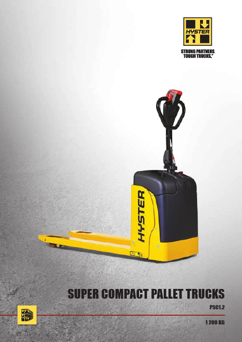
1 200 KGPSC1.2SUPER COMPACT PALLET TRUCKSHYSTERSpecification data is based on VDI 2198DISTINGUISHING MARKPSC1.2 Electric (battery)Pedestrian1.2 600 886 11192.1 Service weightkg 2.2 Axle loading, laden front/rear kg 2.3 Axle loading, unladen front/rearkgW E I G H TWEIGHT153 - 155438 910 114 313.1 Tyres: solid rubber, superelastic, pneumatic, polyurethane front/rear 3.2 Tyre size, front ø (mm x mm)3.3 Tyre size, rearø (mm x mm)3.4 Additional wheels (dimensions)ø (mm x mm)3.5 Wheels, number front/rear (x = driven wheels) 3.6 Tread, front b 10 (mm)3.7Tread, rearb 11 (mm)T Y R E S , C H A S S I STYRES, CHASSISSolid rubber / Polyurethane 186 x 50 82 x 60 75 x 251x + 2 / 2369 3715.1 Travel speed, laden/unladenkm/h 5.1.1 Travel speed, laden/unladen, backwards km/h 5.2 Lift speed, laden/unladen m/s 5.3 Lowering speed, laden/unladen m/s 5.8 Max. gradeability, laden/unladen %5.10 Service brakeP E R F O R M A N C E D A T APERFORMANCE DATA4.3 4.8 4.3 4.8 0.03 0.04 0.05 0.02 10 25Electric6.1 Drive motor S2 60 minute rating kW 6.2 Lift motor, S3 15% ratingkW6.3 Battery according to DIN 43531/35/36 A,B,C, no 6.4 Battery voltage/nominal capacity K 5 (V)/(Ah) 6.5 Battery weightkg6.6 Energy consumption according to VDI cyclekWh/h at number of cyclesE L E C T R I C - E N G I N EELECTRIC - ENGINE0.35 0.4 No24 / 50 28 0.288.1 Type of drive unit D R I V E /L I F T M E C H A N I S MDRIVE/LIFTMECHANISMMOSFET 10.7 Sound pressure level at the driver’s seat dB (A)A D D I T I O N A L D A T AADDITIONAL DATA674.4 Lift h 3 (mm)4.9 Height of tiller arm in driving position min./max. h 14 (mm)4.15 Height, loweredh 13 (mm)4.19 Overall length (pedestrian) l 1 (mm)4.20 Length to face of forks (pedestrian) l 2 (mm)4.21 Overall widthb 1 / b 2 (mm)4.22 Fork dimensions DIN ISO 2331 s / e / l (mm)4.25 Outside Fork Widthb 5 (mm)4.32 Ground clearance, centre of wheelbase m 2 (mm)4.33Load dimension b 12 × l 6 crosswaysb 12 × l 6 (mm)4.34.1 Aisle width for pallets 1000mm x 1200mm crossways (pedestrian) Ast (mm)4.34.2 Aisle width for pallets 800mm x 1200mm lengthwise (pedestrian) Ast (mm)4.35 Turning radius (pedestrian) Wa (mm)1.1 1.2 1.3 1.4 1.51.61.81.92.12.22.33.1 3.23.33.43.5 3.63.75.15.1.15.25.35.85.106.16.26.3 6.46.56.68.110.7D I ME N S I O N SDIMENSIONS200885 1345 85 1510 360 520 551501150520 301000 x 12002079 1977 1268 4.44.94.154.194.204.214.224.254.324.334.34.14.34.24.35l2lsm2h14h13cy138l1h3QW aetraction and hydraulic controls.n Battery discharge indicator.n Welded fork construction makes them highly resistant to torsion and heavy loads.n In case of collision components and batteries are protected with special designed cover.PRODUCTIVITYn Compact chassis design to improve accessibility.n Operator-friendly tillerhead controls for productive load handling.n Standard anti-roll back system.n Stabilizing wheels to maximize stability when turning.ERGONOMICSn Ergonomically tiller head designed for maximum operator comfort.n Low effort controls ergonomically placed to reduce operator fatigue.n Adjustable performance setting to suit specific operation conditions.n Responsive butterfly switches control travel direction, speed and braking allow a smooth start, controlled braking and acceleration. n Creep-speed function for manoeuvring in dense areason-site recharge.n Optimized battery packs to ensure maximum time of operation.n Easy access to motor and key components to reduce downtime.SERVICEABILITYn Quick accessibility for exchange of batteries.n Maintenance free sealed batteries.@fwww.hyster.eu*********************/HysterEurope @HysterEurope/HysterEuropeSTRONG PARTNERS. TOUGH TRUCKS.TMFOR DEMANDING OPERATIONS, EVERYWHERE.Hyster supplies a complete range of warehouse equipment, IC and electric counterbalanced trucks, container handlers and reach stackers. Hyster is committed to being much more than a lift truck supplier.Our aim is to offer a complete partnership capable ofresponding to the full spectrum of material handling issues: Whether you need professional consultancy on your fleet management, fully qualified service support, or reliable parts supply, you can depend on Hyster.Our network of highly trained dealers provides expert,responsive local support. They can offer cost-effective finance packages and introduce effectively managed maintenance programmes to ensure that you get the best possible value. Our business is dealing with your material handling needs so you can focus on the success of your business today and in the future.HYSTER-YALE UK LIMITED trading as Hyster Europe. Registered Address: Centennial House, Building 4.5, Frimley Business Park, Frimley, Surrey, GU16 7SG, United Kingdom.Registered in England and Wales. Company Registration Number: 02636775.HYSTER,and FORTENS are registered trademarks in the European Union and certain other jurisdictions.MONOTROL® is a registered trademark, and DURAMATCH andare trademarks in the United States and in certain other jurisdictions.Printed in Netherlands. Part number: 3990113 Rev00-12/14-TLCHYSTER EUROPECentennial House, Frimley Business Park, Frimley, Surrey, GU16 7SG, England.Tel: +44 (0) 1276 538500。
110KV所内各设备铭牌
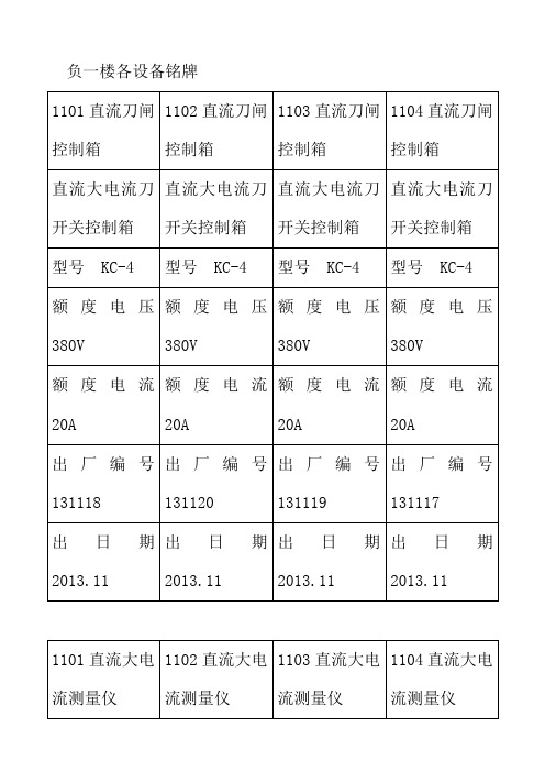
负一楼各设备铭牌
机房纯水冷却器
整流变压器铭牌
有载调压整流变压器(整流变压器部分)
有载调压整流变压器(调压变压部分)
电动机构
有载分接开关在线净油装置
CJ6B电动操动机构
冷却器总控柜
油风冷却器
1105有载调压电力变压器
电流互感器参数
1105电动机构
露天变
1105电动操动机构
主控楼低压室
低压抽出式开关柜
冷却塔
1100母联高压六氟化硫断路器
卧式离心泵
整流循环水泵电机
纯水冷却泵电机
管道式潜油离心泵
整流消防泵电机
整流消防泵电机
生活水泵电机
空压循环水泵电机。
隔离开关技术规范书

隔离开关技术规范书内蒙古华电街基风电项目一期工程220kV升压站220kV隔离开关技术条件买方:内蒙古华电街基风电有限公司设计:张家口先行电力设计有限公司2009年06月28日目录1供货范围 (1)2项目概况 (1)3总的要求 (2)4项目环境 (3)5通用要求 (4)6技术要求 (7)7图纸及资料 (10)8技术服务、设计联络、工厂检验和监造 (12)9试验 (13)10质量保证和管理 (13)11附录 (16)1供货范围2项目概况2.1 项目名称:华电新能源开鲁小街基49.5MW风电项目2.2 项目单位:华电新能源发展有限公司2.3 工程规模:本期220kV电气终期主接线单母线接线,220kV出线( 1 )回。
变压器 1 ×50 MV A。
2.5 交通、运输:铁路,公路。
2.4 工程地址:内蒙通辽开鲁小街基风电场区220kV升压站。
35kV终期主接线为单母线分段,最终出线(6回),本期主接线单母线分段接线,出线( 3 )回。
3总的要求3.1投标须知3.1.1投标人或供货厂必须有权威机构颁发的ISO-9000系列的认证证书或等同的质量保证体系认证证书。
投标人或供货厂(包括分包厂)应设计、制造和提供过同类设备,且使用条件应与本工程相类似,或较规定的条件更严格,至少有 3 台套 2 年以上的商业运行经验。
3.1.2投标人应仔细阅读招标文件。
投标人提供的设备的技术规范应与本规范书中提出的要求相一致,投标人也可以推荐满足本规范书要求的类似定型产品,但必须提出详细的技术偏差。
3.1.3本规范书提出了对户外交流高压隔离开关和接地开关本体及其附属设备的技术要求。
主要包括设备的使用条件、主要技术参数、结构、性能、试验及所需技术资料等方面的内容。
3.1.4本招标书提出的是最低限度的技术要求,并未对一切技术细节做出规定,也未充分引述有关标准的条文,投标方应按有关标准提供符合IEC标准、国标、行标和本规范书的优质产品。
SMC LEC#6系列电动执行器控制器简易操作手册

Parameter(参数)命令 退出本软件 ②View:下设命令包括
LEC 系列电缸简易操作手册
LEC 系列控制器为 SMC 开发的新型电缸控制器。
适用范围:LE 全系列电缸
LES 系列电动滑台
LEY 系列出杆式电缸
LEF 系列无杆式电缸
LEH 系列电动夹爪
LER 系列电动摆缸
1、产品特点:
①内部可存储 64 步程序 ②可实现精确定位、力矩输出
2、系统构成(以 LES 系列电动滑台+LEC 系列控制器为例)
A5
IN2
步选择信号
A6 IN3
A7 IN4
A8 IN5
描述 DC24V 正 DC24V 负 2 进制组合选定要执行的程序步号,OFF 表示 0,ON 表示 1。
IN5 IN4 IN3 IN2 IN1 IN0 步号 000000 0 000001 1 000010 2 。。。。。。
1 1 1 1 1 1 63
配线图(以 NPN 型为例)
输入信号: 线号 线色 A1 茶/黑 1 A2 茶/红 1 A3 黄/黑 1 A4 黄/红 1 A5 浅绿/黑 1 A6 浅绿/红 1 A7 灰/黑 1 A8 灰/红 1 A9 白/黑 1 A10 白/红 1 A11 茶/黑 2 A12 茶/红 2 A13 黄/黑 2 输出信号: 线号 线色 B1 黄/红 2 B2 浅绿/黑 2 B3 浅绿/红 2 B4 灰/黑 2 B5 灰/红 2 B6 白/黑 2 B7 白/红 2 B8 茶/黑 3 B9 茶/红 3 B10 黄/黑 3 B11 黄/红 3 B12 浅绿/黑 3 B13 浅绿/红 3
CJ6G电动操作机构使用说明书
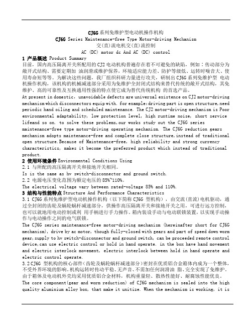
CJ6G系列免维护型电动机操作机构CJ6G Series Maintenance-free Type Motor-driving Mechanism交(直)流电机交(直)流控制AC (DC) motor dc And AC (DC) control1 产品概述Product Summary目前,国内高压隔离开关所配用的CJ2电动机构普遍存在着不可避免的缺陷,例如∶传动部分为敞开式结构、需要定期加油润滑或维护保养,环境适应能力差、防护等级低、运转时噪音大、使用寿命短等等。
为解决这些问题,我厂组织科研力量进行攻关,研制出CJ6G系列免维护型电动机操作机构,该机构的机械减速部分采用为免维护全封闭式结构来替代传统的敞开式结构,其免维护、高的可靠性及互换通用性强的特点使它成为替代传统机构的首选产品。
At present in domestic,unavoidable defects are universal existence on CJ2 motor-driving mechanism which disconnectors equip with. for example:driving part is open structure,need periodic hand oiling and scheduled maintenance. The CJ2 motor-driving mechanism is Poor environmental adaptability, low protection level, high runtime noise, short service lifeand so on. to solve these problems,our works study out the CJ6G series maintenance-free type motor-driving operating mechanism. The CJ6G reduction gears mechanism adopts maintenance-free and complete close structure,instead of traditional open structure.Because of Maintenance-free, high reliability and strong currency characteristics, makes it become the preferred product which instead of traditional product.2 使用环境条件Environmental Conditions Using2.1 与所配的高压隔离开关和接地开关相同。
CJ6B电操机构
CJ6B电动机操动机构安装使用说明书西安世科电器产品有限责任公司XIANSHIKEDIANQICHANPINYOUXIANGONGSI一、概述CJ6B电动机操动机构是我公司继CJ6A电动机操动机构之后又一系列隔离开关用电动机操动机构。
本产品具有结构简单、功能可靠、体积小、重量轻、噪音低等优点。
本产品符合GB1985-89《交流高压隔离开关和接地开关》。
产品可10年免维修。
本产品适合126Kv高压隔离开关、接地开关电动操作使用。
二、技术参数1.适用于高压隔离开关及接地开关的参数详见表1表12.电动机操动机构的额定参数见表2表23.适用环境:3.1 海拔高度:一般≤1000m;特殊情况≤2500m;3.2 环境温度:上限+400C 下限-250C,极限最低温度-400C;3.3 相对湿度:95%RH;3.4 地震烈度:能满足8度的要求;3.5 覆冰厚度:不大于20mm;3.6 污秽等级:III级;3.7 不适用于有易燃物质、爆炸危险、化学腐蚀及剧烈振动场所。
三、操动机构特点1.实用性强1.1 机构接通电源就能在‘就地’或‘远方’进行操作,一台电机通过两级蜗轮减速器输出转矩,就可驱动隔离开关或接地开关准确、可靠地实现合闸、分闸动作。
1.2 利用行程(微动)开关控制操动机构输出转角或它运行的最终位置。
利用蜗杆蜗轮传动保证需要的输出转矩和速度,本机构操作平稳、冲击力小,噪音低,并具有可靠的自锁性。
1.3 本机构可分别实现电动和手动操作,电动和手动能互锁。
1.4 箱体为冷轧钢板喷塑处理(或根据用户要求采用不锈钢板)铆接结构。
其外形美观、结构合理,具有可靠的防水、防尘、防腐及防锈蚀性。
对各种地域均能适应,与传统的焊接和螺栓连接结构相比,更为轻巧和美观。
2.经济性2.1 只需电源电压就能操作,不需其它附属设备;2.2 机构零部件标准化程度高,便于加工制造;2.3 产品价格合理。
3.维护、检查简单3.1 本操动机构结构简单,维护简单方便易行,零部件具有互换性;3.2 机构内的轴承及两级蜗轮减速器都是密封式结构,采用油脂润滑,可不加油,免维护;3.3 打开正门或侧门,可方便实施维护和检查。
CJ6电动机构

CJ6 电动机构使用说明书浙江中意电气有限公司一、概述CJ6型电动机构系AC380V、AC220V、DC110V异步电动机驱动,通过齿轮及涡轮减速的操动机构。
它主要用来操作500千伏及以下湖外高压隔离开关。
CJ6型电动机构配有手柄,可以在现场进行手动操作。
本产品使用条件:(1)环境温度不高于+40℃,不低于-30℃。
(2)相对湿度不大于90%(+25℃时)。
(3)地震烈度不大于8度(4)不能使用在有严重化学腐蚀、盐雾、可燃性气体及强烈震动等地区。
(5)不能用于非水平安装场所。
二、结构及工作原理CJ6型电动机机构系电动机驱动,通过一套机械减速装置将力矩传递给机构主轴,安装时借助于钢管连接使隔离开关主闸刀或接地刀分合闸。
电动机机构由电动机、机械减速传动系统、电气控制系统及箱壳组成。
电动机为三相交流异步电动机,机械减速传动系统包括齿轮、蜗杆、蜗轮及输出转轴。
蜗杆端部为方轴、可装手动摇柄进行手动操作。
电气控制部分包括电源转换开关、控制按钮(分、合、停各一个)、交流接触器、行程开关、热继电器及辅助开关等。
箱壳由钢板制成,起支撑及保护作用,为便于安装及检修,在正面和侧面各有一门。
通过电气控制系统控制电动机,电动机通过两对齿轮传递给蜗杆-蜗轮,带动输出主轴。
减速系统为三次减速,地一二次为齿轮减速,第三次是蜗杆蜗轮减速。
齿轮减速使用规格不同的齿轮可组成两种传动比,故使总的传动比也有两种,第一种使电动机机构分闸或合闸一次动作时间为7.5秒。
第二中使电动机机构分闸或合闸一次动作时间为3秒。
电气控制原理见图3,机构分、合闸按钮(或远方控制)控制接触器,接触器控制电动机,终止位置靠行程开关切断控制电路。
“停”按钮供异常情况时紧急停止使用。
电动机机构动作程序如下:先关合电源转换开关接通电源,分闸时手按分闸按钮(或远距离按钮)将分闸用交流接触器的控制线圈接通,接触器常开触头闭合,使三相交流电接通,电动机向分闸方向旋转,通过二级齿轮减速,再经蜗杆、蜗轮减速后将力矩传送给机构主轴,使主轴旋转180度。
LEC#6系列电动执行器控制器简易操作手册.
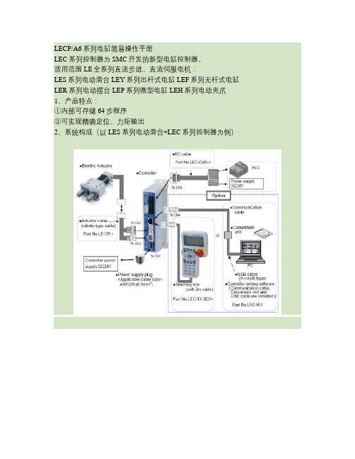
LECP/A6系列电缸简易操作手册LEC系列控制器为SMC开发的新型电缸控制器。
适用范围LE全系列直流步进、直流伺服电机:LES系列电动滑台 LEY系列出杆式电缸 LEF系列无杆式电缸LER系列电动摆台 LEP系列微型电缸LEH系列电动夹爪1、产品特点:①内部可存储64步程序②可实现精确定位、力矩输出2、系统构成(以LES系列电动滑台+LEC系列控制器为例)3、产品结构4、各端口配线及功能详解4-1 CN1端口-DC24V电源接口4-1-1急停信号配线:(注意:常闭信号,闭合时正常使用,断开时急停)4-1-2解锁信号配线:(注意:闭合时解锁,断开时锁紧,适用于带锁型电缸手动解锁用,运动时无需解锁)4-2 CN2端口-电机电源接口/CN3端口-电机编码器接口/CN4端口-通信线缆接口以上3个端口均为标准插头,直接插入端口即可。
4-3 CN5端口-控制I/O接口CN5端口用标准线缆示意图:配线图(以NPN型为例)输出信号:注意:上表中粗体红字部分的线为必接线,否则电缸无法正常使用。
其余线缆可根据实际需要选接。
5、编程软件的安装、使用5-1 编程软件的安装①将软件安装盘放入电脑光驱,然后用通信线缆将电脑与控制器联接。
②系统出现入如图所示提示,按照图中红圈指示操作。
③点击“NEXT”后将出现如下界面,按照图中红圈指示操作。
④点击“NEXT”后将出现如下界面,按照图中红圈指示操作。
⑤点击“FINISH”,完成软件安装。
⑥安装完成后,桌面上将出现如下图标。
双击即可进入编程软件。
5-2 通信端口匹配①在桌面的“我的电脑”图表上点击鼠标右键,选择“属性”,出现如下界面,按红圈指示操作。
②点击“设备管理器”查看系统分配给LEC系列控制器的端口编号(例:COM4),记录下来。
注意:如果在“设备管理器”下面的“端口(COM&LPT)”一栏下没有发现SMC产品项及端口号,请检查“设备管理器”界面下的“端口(COM&LPT)”及“通用总线串行控制器”两项中有无黄色问号项,如果有,则驱动未能完全安装。
CJ6A、CJ6B讲课资料2

CJ6A/CJ6B 电动操作机构讲义一、CJ6A电动操作机构及标识:1、 A 进型序号动机构R:电阻;电路中两点间在一定电压下决定电流强度的一个物理量。
V:电压;静电场或电路中两点间的“电位差”。
A:电流;电荷的流动,例如:金属中自由电子的流动。
电机;根据电磁感应定律和电磁力定律,使电能和机械能相互变换的旋转机械,主要由定子和转子组成。
常开触点常闭触点分合闸按钮。
灯停止按钮行程开关HS 加热器。
整流二极管地线。
电源(火线)RV40/90低温油脂润滑油(寒冷地区使用);GH:表示B相操作用机构(主刀闸使用);G;表示边相导电用操作机构(A、C相使用);DH:表示B相接地刀用操作机构;D:表示边相接地刀用操作机构。
二、CJ6A电动操动机构的特点:制作工艺和设计均采用国内先进技术,其结构方面消化,吸收了当今国外同类产品的先进技术,使该产品与日俱增具有先进性和新颖性。
结构简单、可靠、实用、体积小、重量轻,嗓音小的特点由一台交流电动机、两极蜗轮减速器和电器控制原件组成分闸或合闸时间误差±1秒。
三、适用于高压隔离开关及接地开关的参数。
四、电动机操动机构的额定参数五、适用环境海拔高度不太于3000m;环境湿度上限+40℃下限-25℃;极限最低湿度-40℃(需要特殊订货)。
相对湿度:85%RH。
地震烈度:能满足8级的要求;覆冰厚度不大于20mm;污秽等级3级。
不适用于有易燃物质,爆炸危险,化学腐蚀及剧烈震动场所。
六、手动操作1、手动操作时把正面箱门打开,向上拉手动闭锁把手3-5mm。
此时受力触点,SP7接通电磁铁通电动作,闭锁板的限位被打开,闭锁板可继续向上移动,至露出手柄入孔,把手柄插入,通过手摇可操动机构分合闸,当闭锁板开启至可插入手柄位置的同时,压下了闭锁微动开关。
使就地和远方的电动操作控制回路都被切断,实施了手动和电动连锁。
抽出手柄,闭锁板可自动复位盖住手柄插入孔,此时不能进行手动操作,同时,就地远方的电源接通,可以进行电动操作,仍然保持手动和电动联锁。
操动机构原理介绍及检修
一、隔离/接地开关用操动机构
1.电动操动机构
示例
CJG1
CJG2
CJG6
CJA6
CJG3~5 CJ6系列
CJG1电动操动机构
技术参数
额定输出力矩:
200N·m
输出拐臂转角:
130º
电动机额定电压: DC220,AC220
控制回路额定电压: DC220,DC110
电动机额定功率: 100W
电动合闸/分闸时间: <9s
电动机额定功率: 180W
电动合闸/分闸时间: ≤4s
广泛用于国内各电站,并出口到香港、
新加坡、马来西亚等国家和地区。
CJG3电动操动机构结构紧凑、合理、性能稳定、工作可 靠,属国内领先、世界先进水平。
技术参数
输出转角:
90º
电动机额定电压: DC220,AC220
控制回路额定电压: DC220,DC110
分、合闸 辅助开关切换 位置指示器切换 缓冲器吸收余能
输出轴正、反转
减速装置
齿轮或蜗轮蜗杆
3.电动弹簧操动机构
示例
CTG1 CTA3
CTG2
CTG3
CJG7
图 3 传动原理示意图(分闸位置)
206a.合闸缓冲器 206b.分闸缓冲器 301.电机
302. 蜗杆 303.
蜗轮 304. 弹簧拉杆 305.挂簧拐臂 306.传动销 307.输出凸轮
用于兰州东、大唐彬长、甘肃永登 变等多个工程。
CJA2电动操动机构结构紧凑,操作方便,性能可靠, 属国内领先、世界先进水平。
CJ6A电动机操动机构
技术参数
额定扭矩:
300~1200N·m
控制回路电压: AC220/DC220
The Crosby Group LLC 国家六杆筋筒机和钢丝筒警告、使用、维护和应用信息说明书

NATIONAL SWAGING MACHINEAND DIE WARNING, USE, MAINTENANCE AND APPLICATIONINFORMATION National Four Post Swaging MachineOperation Safety• NEVER use dies that are cracked, worn or abraded (galled).• NEVER use dies that have an oversized cavity.• ALWAYS use a matched set of dies.• When swaging steel fittings,DO NOT SHIM DIES. Dies for steel fittings must be free to float and align one to the other.• When swaging aluminum fittings, THE STEEL DIES MUST BE SHIMMED. Shim the side of the die to ensure the proper cavity alignment for flash removal.• NEVER shim between the dies.• When Swaging Crosby National fittings, use only the proper capacity swaging machine for the size of fitting used (See Swaging Capacity Chart). If the swaging machine capacity exceeds the die block Working Load Limit rating, adjust the swagingmachine tonnage to the Working Load Limit shown on the die block being used. See Table 1 for die block Working Load Limit.• Always use the correct size and type of die for the size wire rope fitting used.• Make sure that the manufacturer’s die retentionlocking pin, bolt, or other device is engaged and has secured the die before swaging. Make sure that the dies are straight, parallel, and perpendicular to each other before and during the swaging procedure.• Always lubricate die faces and cavities with light weight oil.• Progressive swaging of fittings must be done in accordance with procedure shown in “Wire Rope End T erminations User’s Manual”. Only open channel dies are to be used.• Stop swaging when the cavity side of both dies touch. Observe the die closure from above and slightly to the side. The best position is to stand 45 degrees to either side of the front.• Make sure part is swaged to the recommended after swage dimensions (See Crosby General Catalog or “Wire Rope End Terminations User’s Manual”, Die Guide, or Die Chart).• If a swage fitting other than a Crosby National is used, determine adequacy of the termination by a destructive pull test.• All swage sockets must be swaged with socket head adjacent to the socket relief (largest radius) on the die.• For special applications or conditions, contact Crosby National (501)962-3112.* Note: These Working Load Limits are for Crosby ® National Die Blocks only. The Working Load Limits of die blocks from other manufacturers may vary.• Make sure the swager is in good operating condition and that all gauges, indicators and controls are working properly.• Make sure all bolts and nuts are in place andtightened to recommended torque as shown in Table A, on page 13 for new style swaging machines, and T able B on page 14 for current swaging machines.• Load block or die base plate surfaces must be to manufacturers specifications for thickness and flatness to provide complete support of the die during swaging.• Make sure die holder side rails are not bent, loose or damaged.• Clean dies and die holder surfaces. Keep free of metal shavings, slag, grit, sand, floor dry, etc.• Lubricate the four guide bushings daily with light oil.Die Working Load Limit Pressure Adjustment on Lower Cylinder National 500 Ton through1500 Ton Swaging MachinesFollow this procedure to adjust swaging tonnage (pressure) on your swaging machine.1. Install the die holder(s) or die adapter with the dies to be used.2. Bring the dies together (without a part in the dies) until they just touch.3. T urn the tonnage control valve, which is located on the control panel left of the tonnage gauge, counter-clockwise about (6) six turns or until knob no longer turns.4. Now (without a part in the dies) apply pressure to the dies by pressing the foot pedal marked “up”.A. If the tonnage is lower than desired Working Load Limit, turn the valve clockwise while continuing to press the foot pedal marked “up” until desired Working Load Limit is reached.B. If tonnage is higher than desired Working Load Limit, release pressure by pressing the pedal marked “down”. Then repeat steps 2 through 4.Swaging Machine Capacity Chart for Swage Sleeves, Ferrules and ButtonsSwaging Machine Capacity Chart forS-501 and S-502 Swage Socket• Inspect the rods for corrosion. Use #000 emery cloth or steel wool to maintain a high polish surface.• Do not increase the hydraulic system pressure above the factory preset pressure of: 6500 psi for 500 ton, 1000 ton and 1500 ton swaging machines – 5000 psi for 3000 ton swaging machine.• Under ordinary operating conditions, drain and clean reservoir every two (2) years.• Make certain that the hydraulic reservoir is full when the swager is in the full open position.• Filters inside of the reservoir should be cleanedevery time the reservoir is drained and cleaned. The Racine “tell-tale” suction filter should be cleaned every six (6) months.Inspection Maintenance Safety“NEW STYLE” NATIONAL HYDRAULIC SWAGING MACHINEBolt SizeThreadFormTorqueinft./ lbs. DieHolderBoltTorque1/4 20 UNC135/16 18 UNC155/8 11 UNC2117/8 9 UNC583NATIONAL HYDRAULIC SWAGING MACHINE TORQUE MAINTENANCE INFORMATIONItemNo. Req’d.Description11Cylinder21Housing Cap 31Piston 44Tie Rod 58Nut 61Platen 72Guide 81Gland 94Bushing 101Packing Set1112Packing Gland Nut 124Packing Gland Spacer 1312Stud144Cap Screw 154Cap Screw 162Lower Bracket171Upper Bronze Ring 182Upper Bracket 198Machine Screw 202Side Cylinder211Lower Bronze Ring A 1Block B 4Stud C 4NutD 1Copper “O” RingE 4Lock NutX 1Top of CylinderY1Bottom of Packing CavityBolt Size Thread FormTorque in ft./ lbs.Die Holder Bolt T orque1/4 20 UNC 135/16 18 UNC 155/8 11 UNC 2117/8 9 UNC583National dies and die holders are made solely for swaging properly designed fittings on wire rope, and any other uses are prohibited.The swaging operation results in a high degree of cold metal flow. The movement that occurs between the fitting and the dies will cause wear of the dies. Therefore,to prolong the life of the dies, it is important to always lubricate die faces and cavities between each pass with a light weight oil or high pressure grease.When scores appear in the die cavities, the dies should be removed from service.NEVER EXCEED THE WORKING LOAD LIMIT OF DIES OR DIE HOLDERS.All National Standard dies 1/4” through 1” include an open channel die cavity and a tapered die cavity in the same die block.Dies for S-505 Standard Steel Sleeves(Flemish Eyes)Die sizes for 1/4” through 1”Swaging 1/4” through 1” Standard Steel S-505 sleeves on Flemish Eye terminations requires the use of the taper cavity only. Refer to page 24 of the Wire Rope End T ermination User’s Manual for proper die selection.Die sizes for 1-1/8” and aboveSwaging 1-1/8” and larger Standard Steel S-505 sleeves on Flemish Eye terminations requires using 2 sets of open channel dies (1st stage and 2nd stage) for each size. Beginning with the 1st stage die and finishingwith the 2nd stage die will achieve proper after swage dimensions. Dies for S-505 Sleeves 1-1/8” and larger are single cavity with open channel. Refer to page 24 of the Wire Rope End T ermination User’s Manual for proper die selection.Using S-505 Sleeves with Metric RopesAlthough Crosby National S-505 Standard Steel sleeves are designed to be used with most metric ropes, there are selected “intermediate” sizes of metric ropes that when swaged in standard National dies utilizing Crosby National S-505 sleeves do not achieve required after swage dimensions and efficiencies. T o ensure all 505 sleeves achieve the required efficiency when used with metric ropes, Crosby provides special National swaging dies to be used in conjunction with selected sizemetric ropes. These new dies will produce the required efficiencies and after swage dimensions.The table found on Page 25 of the Wire Rope EndT ermination User’s Manual identifies the new dies that are required to properly swage the selected intermediate size wire ropes not covered in the standard product offering found on Page 24 of the manual.Dies for 6mm through 26mm (except 12mm, 20mm and 24mm)Swaging on 6mm through 26mm metric ropes for Flemish Eye slings requires the selection of the proper S-505 Standard Steel sleeve and the use of the tapered cavity only. Refer to page 24 of the Wire Rope EndT ermination User’s Manual for proper sleeve anddie selection.Dies for 12mm, 20mm and 24mmSwaging on 12mm, 20mm and 24mm metric ropes for Flemish Eye slings requires the selection of the proper S-505 Standard Steel sleeve and the use of both the open cavity and tapered cavity in special dies. Referto page 25 of the Wire Rope End T ermination User’s Manual for proper sleeve and die selection.Dies for 28mm and largerSwaging on 28mm and larger metric ropes for Flemish Eye slings requires the selection of the proper S-505 Standard Steel sleeve and the use of 2 sets of open channel dies (1st stage and 2nd stage) for each size. Beginning with the 1st stage die and finishing withthe 2nd stage die will achieve proper after swage dimensions. Dies for S-505 sleeves 28mm and larger are single cavity with open channel. Refer to page 24 of the Wire Rope End T ermination User’s Manual for proper sleeve and die selection.Important: If the specific size metric rope required isnot listed on page 24 of the Wire Rope End T ermination User’s Manual refer to Intermediate Metric Die Chart on page 25 of the manual for proper sleeve anddie selection.Dies for QUIC-PASS® Swaging System – 1/4”through 1-1/2”The QUIC-PASS® swaging system allows “Flemish style” wire rope terminations to be swaged in only two passes. This is accomplished while maintaining currently published efficiency ratings and utilizing National Swage S-505 Standard “COLD TUFF”® Steel Sleeves.The special design of the QUIC-PASS® dies allows the swaging process to be completed in just two passes, resulting in a 50-75% reduction in the number of passes required with conventional swaging systems. Unlike standard round dies, the QUIC-PASS® dies close completely with each pass, resulting in an increase in overall swaging process efficiencies (the job can be performed quicker), a reduction in the complexity of swaging (the concern for excess flashing between dies has been eliminated) and a reduction in training time needed for operators (more user friendly).The finished sleeve has a “Hex” appearance that provides a QUIC-CHECK® look to determine if the termination has been swaged and provides a flat surface that allows for ease of I.D. stamping on the finished sleeve. Refer to page 24 of the Wire Rope End T ermination User’s Manual for proper die selection.Die InformationSingle Cavity DieTwo Cavity DieDies for S-501 & S-502 Swage SocketsSwaging all S-501 & S-502 Swage Sockets requires the use of single cavity die. This is a special die designed with a relief for swage sockets and extra length to swage the full length of the shank. Refer to pages 36 and 37 of the Wire Rope End T ermination User’s Manual for proper die selection.Swage Sockets for Spiral Strand RopeOur tests indicate that if the spiral strand is 1 x 19 or greater, and the ultimate strength does not exceedT able 4 of ASTM A586, you can use dies for size swage sockets up to the 1-1/4”. For sizes greater than 1-1/4” the following table will apply:If the strand is of greater strength than T able 4 or has less metallic area, we must recalculate the design and test for adequacy.Dies for S-506 Turnback SleevesT urnback eye terminations using 5/16” through 1” S-506 Sleeves utilize the S-505 Standard Steel Sleeve die (1st Stage open channel die only). The 1-1/4” S-506 Sleeve utilizes the 1-3/8” socket (S-501 and S-502) die. Refer to page 46 of the Wire Rope End T ermination User’s Manual for proper die selection.Dies for S-409 ButtonsButtons are swaged in open channel dies. Refer to page 42 of the Wire Rope End T ermination User’s Manual for proper die selection.Specific recommended swaging practices can be found in each product section of this brochure. The proper die selection and the recommended maximum after swage dimensions are referenced in the section of this brochure that contains the product you are swaging. This information can also be found in The Crosby General Catalog (See Section “Wire Rope End T erminations”), the National Swage Die Guide, or by referring to the National Swage Die Chart.Dies and die adapters to fit other type swaging machinesare available upon request (Refer to page 19).Never use dies that are cracked, worn or abraded (galled).Checking Swaging DimensionsOne of the important considerations in producing a quality termination is the overall diameter of the fitting after the swaging process is complete. Since all dies wear, andthe swaged fitting used in terminations have spring back,the results of swaging should be checked periodically to determine the wear condition of the die as well as to ensure the fitting is swaged to proper dimensions.Key Facts About After Swage Dimensions:1. In addition to worn dies, not achieving the proper afterswage dimension can also be due to the die not beingfully closed during swaging. Dies showing excessive wear should be replaced.2. The effective swaging that dies can accomplish stopswhen the die lands touch each other. Any continuedswaging adds needless wear and strain on the dies and swaging machine.3. By placing a light oil on the die faces and in the cavity, thedies will be lubricated as well as protected.4. The oozing of the oil from the faces of the dies as theytouch will indicate when the dies have closed. At thispoint, stop the swaging cycle.5. Additional swaging adds needless wear and strain to thedies and swaging machine.6. Never use dies that are cracked, worn or abraded(galled).7. The Crosby Group does not recommend the checking ofdie dimensions as an acceptable method of determining the quality of a swage sleeve, button, ferrule, or socket. 8. It is our recommendation that the checking of the afterswage dimension of the swaged fitting is the mostaccurate indicator of a properly swaged termination.Measuring the die cavity only is not an acceptableprocess control check.9. If the die cavity wears, the dies are not closed completelyduring swaging. If an inadequate number of presses are used, it could be quickly identified by checking the afterswage dimension of the part.10. Swaging Machine not producing sufficient tonnage willaffect after swage dimensions.Table 1Fitting and Size Part No.505 Sleeve 1/4 - 7/81095512505 Sleeve 1 - 1-1/21095521505 Sleeve 1-3/41095530505 Sleeve 21095549505 Sleeve 2-1/41095558505 Sleeve 2-1/21095587505 Sleeve 2-3/41095576505 Sleeve 31095565505 Sleeve 3-1/21095594505 Sleeve 3-3/41095601505 Sleeve 41095610501/502 Socket 1/4 - 11095647501/502 Socket 1-1/8 - 1-3/41095656501/502 Socket 21095665No-Go Gauge InformationTo assist in checking the after swage dimensions of the fitting, the Crosby Group provides the National No-Go Gauges. When used correctly the National No-Go Gauges can determine if the fittings were swaged to the proper diameter. We would recommend that all Crosby products or product swaged in Crosby dies be checked with the proper gauge to determine the acceptability of the swaging process.• Gauges are made of hardened alloy steel and machined to strict tolerances.• Gauge can be used to verify that all fittings have been swaged properly.• After swage dimensions not within the maximum limits may result from worn dies or improper swagingtechniques.• Other type gauges are available upon request.• National No-Go Gauges are available for a variety of products (See Table 1).• No-Go Gauges and QUIC-PASS® No-Go Gauges are not interchangeable.Figure 1Figure 2After Swage Inspection ProceduresUsing No-Go GaugesWhen swaged properly, the gauge will go up and down (seeFigure 1) and around the full length of the fitting (see Figure 2).For the proper after swage dimensions, see the section in thispublication for the specific product you are swaging.QUIC-PASS ® No-Go GaugesAs a further aid, QUIC-P ASS ® No-Go gauges are available for checking the sleeve’s dimensions after swaging is complete.• Gauges are made of hardened alloy steel and machined to strict tolerances.• Gauge can be used to verify that all sleeves have been swaged properly.• “After Swage” dimensions not within the maximum limitsmay result from worn dies or improper swaging techniques.Stock No.1923705Stock No.1923714Stock No.1923712113223Use a National QUIC-P ASS ®No-Go Gauge to check the after swage dimensions to ensure that it has been swaged to the proper dimension. When swaged properly, the gauge will slide up and down the full length of the sleeve on all three sets of opposing flats.Important Safety Information• Crosby does not recommend a “T exas T uck” styletermination with Crosby National S-505 “COLD TUFF ®” Standard Steel Sleeves.• Only Crosby National S-505 “COLD TUFF ®” Standard Steel Sleeves are recommended when using the QUIC-P ASS ® Swaging System.• National S-505 Standard Steel Sleeves, when used with the QUIC-P ASS ® Swaging System, are only recommended for use with one (1) part 6 X 19 or 6 X 37, IPS or XIP (EIP), XXIP (EEIP), RRL, IWRC rope.• The condition of the swaging machine can cause sleeve “After Swage” size not to be within the proper dimensions. Example: worn bushings, loose tie rods, loose dieholders, misaligned platens, worn pins, worn linkage, etc.• Swaging dies being worn, damaged, misused, orundersized can cause sleeve “After Swage” size not to be within the proper dimension.• Swaging die holders excessively worn, damaged, misused or loose can cause sleeve “After Swage” size not to be within the proper dimension. Only use QUIC-P ASS ® dies and die holders inspected and properly secured in National swaging machines.• Always refer to Warning and Application informationfound in the Crosby General Catalog and Wire Rope End Terminations User’s Manual.QUIC-PASS ®Maximum After Swage Dimensions。
电动机构说明书(中文)

CJTK〔改良型〕电动操作机构安装使用说明书0TK.466.5017泰开集团XX泰开隔离开关XX二〇一〇年三月目录一、机构的主要特点:3二、储存:3三、CJTK电动机构技术参数表:3四、使用环境条件:4五、构造和工作原理41.构造42、机构安装尺寸53、工作原理5六、安装和调试61、安装前检查62、调试步骤:63、角度调节:6七、常见故障处理:71、电动操作不动作72、接触器不动作或有异常声音7八、考前须知7九、随机文件8十、订货须知8二次原理图错误!未定义书签。
二次接线图错误!未定义书签。
直流电机原理图错误!未定义书签。
直流电机接线图错误!未定义书签。
正常配报警接点原理图错误!未定义书签。
正常配报警接点接线图错误!未定义书签。
直流电机配报警接点原理图错误!未定义书签。
直流电机配报警接点接线图错误!未定义书签。
附录:电动机构投运的条件错误!未定义书签。
CJTK电动机操动机构是交流380V〔或直流220V〕电动机驱动,通过蜗轮、蜗杆两级减速的操动机构,可以用来驱动330kV及以下电压等级的户外隔离开关和接地开关。
CJTK电动操动机构分为CJTKA电动机构和CJTKB电动机构两种。
一、机构的主要特点:1、适用性强:CJTKA电动机构可配用252kV和363kV户外隔离开关和接地开关;CJTKB 电动机构可配用145kV、126kV、72.5kV和40.5kV户外隔离开关和接地开关。
2、CJTK电动机构可靠性高:①、传动系统操作平稳,冲击力小、自锁可靠、噪音低;②、机构的限位装置可有效防止分、合到位后输出轴可能发生的继续转动,保证隔离开关〔接地开关〕不受损伤;③、机构的联锁装置可以满足多种联锁及五防闭锁功能,能有效防止误操作;3、机构采用不锈钢板焊接而成,机构合理、外形美观,并具有可靠的仿佛功能。
4、箱盖采用凸台式机构,能有效的加固箱体;箱体与输出轴的密封采用油封及气体的双层密封,箱门的密封采用的时气囊密封构造,能起到很好的防水、防尘效果,满足防护等级IP54的要求;5、机构整体机构简单,布局合理,零部件具有互换性。
CJW型电动机构安装使用说明书
CJW型系列电动操动机构安装使用说明书天津长澳电器有限公司前言欢迎选购本公司产品。
CJW型电动操动机构是为适配户外直流隔离开关和GW4系列隔离开关而研制的新型电机构。
该产品是本公司积累了国内外几种电动隔离开关操动机构的经验,以优越的技术、可靠的元器件,在严格的质量管理下制成,具有优异的性能,较高的可靠性。
CJW型电动操动机构在分析比较目前国内的电动机构后确定了本公司带电磁离合器等保护的电机操动原理,同时本公司注意到各元器件的质量好坏也是影响产品可靠性的一个重要因素,因此我公司选用了目前最先进的自动开关、接触器等,特制了双铜滑环的电磁离合器及具有三防要求的电动机,在反复比较及寿命试验后确定了现用的辅助开关,这些都确保了产品的可靠性。
本产品结构合理,便于使用和维护。
正确的安装和使用,才能发挥本产品的功能,请您在安装、调试和使用本产品前,详尽阅读本使用说明书。
如果有什么疑问,请与本公司联系,我们将迅速、竭诚为您服务。
谢谢合作!目录1.型号说明2.概述3.使用环境条件4.技术数据5.工作原理与结构6.安装调试7.使用和检修8.包装运输和保存9.成套供应10.订货须知1. 型号说明:C J W —□□2. 概述:CJW型系列电动操动机构是由交流或直流电动机驱动,通过摆线针轮及蜗轮蜗杆减速的操动机构,主要用于操动27.5kV单相及两相电气化铁道专用隔离负荷开关和电动隔离开关。
此型电动机构配有手柄,可以在现场进行手动操作。
3. 使用环境条件:3.1 环境温度不高于+40℃,不低于-40℃。
3.2 海拔高度不超过3000m。
3.3 没有易燃、爆炸危险、严重污染、化学腐蚀及剧烈震动的场所。
4. 技术数据电动机电压(交直流两用)(伏)220/110 电流(安) 2.73/5.46 功率(瓦)360转速(最终输出)r/min 80户外电动操动机构C:DC110VB:DC220VA:AC220VⅠ:上输出1200(GW-1.5用)Ⅱ:上输出900(GW4-27.5用)Ⅲ:上输出1800(GW4-110用)Ⅳ:侧右输出Ⅴ:侧左输出续上表分、合闸线圈(控制)电压(伏)220/110操作时间(分闸或合闸一次)(秒)<4输出转矩(kg.m)50重量(kg)755. 工作原理与结构:5.1 CJW型电动操动机构采用交直流两用电动机驱动,通过一套机械减速装置将力矩传递给机构主轴,安装时借助于钢管连接隔离负荷开关或电动隔离开关进行分、合闸。
110kV主变技术规格书

华陆工程科技有限责任公司工程规范110kV电力变压器技术规格书文件编号: 07001-301- N- 02工程代号:07001项目名称:延长醋酸及其配套工程目录1概述 (1)1.1范围 (1)1.2标准及规范 (1)1.3安装地点 (1)2环境条件 (1)2.1环境温度 (1)2.2相对湿度 (1)2.3海拔高度 (1)2.4年平均风速 (1)2.5最大积雪厚度 (1)3基本技术要求 (2)4供货范围 (2)5试验和检验 (3)6随机技术文件 (3)7涂漆 (4)8铭牌 (4)9产品包装及运输准备 (4)1 概述1.1 范围本规格书用于华陆工程科技有限责任公司设计的延长醋酸及其配套工程中110kV电力变压器设计、制造及安装的基本要求。
1.2 标准及规范变压器的设计、制造和试验应遵循:★ GB1094-1996 电力变压器★ GB/T6451-1996 三相油浸式电力变压器技术参数及要求★ GB4942.2-93 外壳防护等级的分类★ IEC76 电力变压器若采用其他本规格书中未列明的标准规范,则必须征得业主同意。
若文件之间出现冲突,优先遵守的顺序为:·中国国家标准或IEC标准·本技术规格书·工程图纸和其他文件1.3 安装地点:户外2 环境条件2.1环境温度:极端最高温度38.4︒C极端最低温度-29︒C最热月平均温度23.2︒C年平均温度8.6︒C2.2相对湿度:62%2.3海拔高度:1100米2.4年平均风速: 2.2米/秒瞬时最大风速(地上10米):23米/秒最大风压:40kg/m2全年沙暴日数:13.8天2.5最大积雪厚度:15厘米3 基本技术要求本规格书所涉及的电力变压器应为油浸风冷却型铜芯低损耗型有载调压电力变压器,其铁芯应为冷轧晶粒取向优质进口硅钢片,采用波纹膨胀储油柜。
变压器的一次侧进线采用钢芯铝绞线连接,二次侧引出线采用铜母线连接(详见数据表)。
配套变压器中性点接地保护装置。
- 1、下载文档前请自行甄别文档内容的完整性,平台不提供额外的编辑、内容补充、找答案等附加服务。
- 2、"仅部分预览"的文档,不可在线预览部分如存在完整性等问题,可反馈申请退款(可完整预览的文档不适用该条件!)。
- 3、如文档侵犯您的权益,请联系客服反馈,我们会尽快为您处理(人工客服工作时间:9:00-18:30)。
CJ6B电动机构
1 主要用途与适用范围:
CJ系列电动机操动机构,属户外产品,供操作高压隔离开关之用.可进行远方控制,也可就地用电动控制或用摇把进行人力操作。
2 产品的工作条件和工作环境:
2.1 环境温度: -50℃~+50℃;
2.2 海拔:不超过2000m;
2.3 风速:不超过34m/s;
2.4 覆冰厚度:不超过10mm;
2.5 地震烈度:不超过8度;
2.6 空气污秽程度:适用于Ⅳ、Ⅲ级及以下污秽地区;
2.7 无频繁激烈震动,无易燃易爆和化学腐蚀物;
2.8 阳光辐射强度:1000W/㎡(晴天中午);
2.9 不适用于具有大量导电气体、尘埃或足以绛低其电气性能及有爆炸危险的场所;
2.10 不适用于非水平安装的场所;
2.11 电源电压变化范围:额定电压85%~110%。
4.1 CJ系列机构采用电动机驱动涡轮蜗杆减速装置,带动输出轴工作,输出轴采用垂直安装,具有噪音小的特点。
4.2 CJ系列机构中采用电气分、合闸终点限位开关与机械限位装置相配合的方式,使机构主轴限制在准确的位置。
4.3 CJ系列机构箱内设有远、近控开关,可实现就地电动分、合闸操作和远方遥控操作;并可用摇把进行人力分、合闸操作。
通过摇把的插入与拔出,自动实现手动与电动相互闭锁。
4.4 CJ系列机构采用了先进、可靠、免维护的电子式电动机保护器,该保护器是根据隔离开关电动机构的运行特点设计的,采用电流检测技术,无需外电源,对电动机运行中的对称性故障(如过载、堵转等)及非对称性故障(如断相、电流不平衡等)有可靠保护功能。
4.5 CJ系列电动机构内正常装有8常开、8常闭的辅助开关,由转轴带动辅助开关切换,在隔离开关在合闸或分闸位置时发出相应的信号。
4.6 CJ系列电动机构的电气原理及内部结构相同,只有安装背板有所区别,通过变换安装背板,可实现CJ系列机构箱之间的互换和对老型号CJ2、CJ5、CJ6、CJ9操动机构的升级改造。
5 产品系统说明:
5.1 现场就地操作电动机操动机构时,转换开关(QC)打在近控位置。
5.1.1 电动分闸
按下分闸按钮(SB3),分闸接触器(KM2)线圈接通,接触器常开触点闭合并自锁,使电动机启动,电动机驱动涡轮蜗杆减速装置,主轴逆时针方向运动,带动与主轴相连的隔离开关分闸。
当主轴接近分闸终点位置时,装在主轴上的定位件使终点限位开关(SL2)分开,切断分闸接触器的控制线圈电源,接触器常开触点打开,切断电动机电源,机械限位装置使机构限制在分闸位置。
5.1.2电动合闸
按下合闸按钮(SB1),合闸接触器(KM1)线圈接通,接触器常开触点闭合并自锁,使电动机启动,电动机驱动涡轮蜗杆减速装置,主轴顺时针方向运动,带动与主轴相连的隔离开关合闸。
当主轴接近合闸终点位置时,装在主轴上的定位件使终点限位开关(SL1)分开,切断合闸接触器的控制线圈电源,接触器常开触点打开,切断电动机电源,机械限位装置使机构限制在合闸位置。
5.1.3 电动停止
在分、合闸过程中,需要中途停止时,可按下停止按钮(SB2),切断控制电源。
5.2 现场人力操作分、合闸
用摇把直接操作蜗杆轴,进行分、合闸操作。
摇把插入电动机构蜗杆时,摇把使得微动开关SL3打开,控制回路失电,此时能手动操作,不能电动;将摇把拔出时,SL3合上,控制回路得电,即可进行电动操作。
从而实现手动、电动相互闭锁。
5.3 电磁锁
本产品可配电磁锁(DS)以实现机械及电气连锁。
将电磁锁串接在电气回路的常开接点上,当接点接通后,电磁锁得电,按下并旋转电磁锁旋钮至自保持位置,即实现解锁。
操作完成后按下旋钮,电磁锁便自动复位至锁定位置。
在锁定位置无法实现手动操作,解锁后方可实现。
在无电状态下若需解锁,可借助钥匙。
6 安装与调试:
6.1 CJ系列操动机构外形与安装尺寸见图1。
6.2 CJ系列操动机构电气原理接线图见图2。
6.3 安装前应先检查操动机构有无损坏;转动是否灵活;紧固件是否松动;各电气元件是否完好。
确认无损后方可进行安装。
6.4 将机构固定在支架上,支架在承受2000N·m弯矩作用时,应不能产生变形及明显晃动。
此时调整固定基座的4个M16的螺栓,使机构的转轴与隔离开关在同一垂直线上。
将机构箱内配供的接头套在机构输出轴上,使机构和开关同处在合闸位置,再用焊接钢管将隔离开关和机构上的转轴连接起来。
并手动操作数次,确认准确无误后,再按图2进行控制回路接线,同时接上地线。
最后用电动形式操作数次,无误后即可投入运行。
6.5 在额定操作电压85%~110%的范围内,应能保证隔离开关可靠的分闸或合闸。
注意: 1.转换开关QC所处的位置。
2.在通电操作前,使机构处于分合闸中间位置,然后接上电源,按分闸或合闸按钮。
3.观察交流电动机构主轴转动方向是否符合要求。
若相反,立即切断电源,改换电源线的相序。
4.操动机构的分合闸位置不能以辅助开关切换位置确定,必须以机构的机械定位位置确定。
5.由于电动机保护器的输出接口采用无触点的固态式电子开关,故检查开关的通断特性不能简单的用万用表电阻档来测量。
检测其它电路时可以将该接点K1、K2短接。
7 使用与维护:
产品投入运行后,每年定期检查一次,检查下列部分是否正常。
7.1 用摇把操动机构运转,检查各转动部分是否灵活,辅助开关能否正常切换。
7.2 所有紧固件应无松动。
7.3 涡轮蜗杆减速装置、定位件、二次元件等零件应无损坏。
检查完毕后,当确信机构各部件正常,先用手动操作3~5次,后电动3~5次。
只有在隔离开关和操动机构动作正常、二次回路触点正确切换、联锁可靠的情况下,方可投入运行。
注意:在检查或用摇把操动时,必须先切断电源;电动操作时,务必先取下摇把,以免发生意外。
8 验收和储藏:
8.1 用户收到产品后应在15天内按验收项目进行验收,若发现问题须立即告知我公司,以便共同协商处理。
8.2 验收项目如下:
检查包装箱有无破损,检查产品合格证、安装使用说明书、装箱单等文件是否齐全。
8.3 产品拆箱后若不立即安装,应恢复原包装,存放于通风干燥的仓库中,并定期检查(间隔不得超过6个月),若发现受潮或生锈,应除去生锈层,必要时还须进行干燥处理。
9 成套性:
9.1 产品成套供应
a.电动机操动机构1台
b.手柄1只
c.夹件1套
9.2 随机文件
a.安装使用说明书
b.产品合格证
c. 装箱单
10 定货须知:
订货时应说明:机构型号、电机电压、控制电压、机构输出转角、辅助开关节点数等。
11 其它:
产品出厂18个月内,确因制造质量问题发生损坏或不能正常工作时,本公司负责修理或更换零件。
12 附图:
图1:CJ系列操动机构外形与安装尺寸;
图2:CJ系列操动机构电气原理接线图。
附图2:
CJ系列操动机构电气原理接线图附图2:。
