USBLMC_CUH_IPG_V1(3)_USB_IPGYLP卡使用说明
USBLMC_CUH_IPG_V1(3)_USB_IPGYLP卡使用说明

2.4 电源的连接...................................................................................................................... 12 2.5 典型连接.......................................................................................................................... 13
2.1.1 电源................................................................................................................................................ 3 2.1.2 CON1 :DB15 振镜控制.............................................................................................................4 2.1.3 CON2 :DB25 激光控制........................................................................................................... 5 2.1.4 CON3 :DB9 飞标接口................................................................................................................6 2.1.5 CON4:DB15 电源/IO 插座......................................................................................................7 2.1.6 CON5:IDC10 IO 插座................................................................................................................ 8
JCZ-IPGYLP卡使用说明

USBLMC_CUH_IPG_V1(4)USBLMC 用户使用手册IPG YLP系列激光器专用版本记录版本号更新日期更新人更新说明V1.0 2007-1V1.1 2007-6V1.2 2008-5V1.3 2008-5-12 吕文杰同时兼容B型/D型接口的YLP 系列激光器;电源连接方案改变程鹏修改IN0和IN4V1.4 2009-12-12目录安全须知 (1)一、概述 (2)1.1 如何辨识IPG YLP 激光器专用控制卡 (2)1.2 主要特点 (3)1.1 版本说明 (3)二、电气连接 (3)2.1接口说明 (3)2.1.1电源 (3)2.1.2 CON1 :DB15 振镜控制 (4)2.1.3 CON2 :DB25 激光控制 (5)2.1.4 CON3 :DB9飞标接口 (6)2.1.5 CON4:DB15 电源/IO 插座 (7)2.1.6 CON5:IDC10 IO 插座 (8)2.2 跳线说明 (9)2.3 数字输入输出信号的连接 (10)2.3.1输入信号 In4,In8, Start,EMSTOP (10)2.3.1输入信号 In5,In9 (11)2.4 电源的连接 (12)2.5 典型连接 (13)安全须知在安装、使用USBLMC控制卡之前,请仔细阅读本节内容。
若有任何关于本文档的疑问,请联系BJJCZ。
1.安全操作步骤z请遵守所有的关于激光的安全说明(包括但不仅限于描述于激光器、振镜以及本文档中的相关章节)z无论任何时候,请在开启了电脑电源、USBLMC电源及振镜电源之后再打开激光器电源。
否则,可能会因不可控的激光光束而造成伤害。
我们建议您使用光闸来避免不可控的激光造成的伤害。
2.客户负责的安全部分z USBLMC被设计用来控制一个激光扫描系统。
因此,所有有关激光系统的安全指示都应该被客户了解并施行。
客户必须严格遵守相关的安全操作指示并独立地负责所用的激光系统的安全。
z安全规则可能因国家不同而有所差异。
韩国天娱瑞酷飞图至尊IP摄像头用户指南说明书
Perfect picture qualityWhen monitoring colorful scenes with a high amount of activity, seeing all the details is critical for safety and security. Part of the Bosch high definition (HD) portfolio, the Dinion and FlexiDome HD 1080p Day/ Night IP cameras deliver uncompromising vision even in the busiest scenes. Combining very high resolution images with excellent low light operation and color reproduction, these high quality systems deliverbest-in-class performance.A specially selected image sensor delivers superior detection and analysis even in low light conditions. Images are clearer and have less motion blur, making it easier to identify items. They also require less bandwidth to transmit due to reduced image noise. Even in low light conditions, first-class color reproduction delivers a clear differentiation between color tonesSmart Backlight Compensation (BLC) automatically compensates the image by optimizing light levels for objects of interest without compromising the Dynamic Range. Additionally, the sharpness slider applies detail enhancement to the whole scene, while sharpness automatically enhances every pixel. Reduced storage, automatic scene analysisand alarm functionalityH.264 video compression ensures the best image quality, while minimizing storage and bandwidth requirements. Bosch IVA can analyze a scene and alert your security personnel to any suspicious activity. Alarm functionality enables you to trigger alarm systems or start the camera recording when an event is detected. And, audio lets you hear as well as see what is going on. The camera sends an alarm for sudden or loud noises, alerting your security team to a potential problem.Local Storage & Automatic Network Replenishment (ANR)Dinion HD & FlexiDome HD cameras support local storage with a microSD card. The cameras support SXHC microSD cards and can use microSD cards with up to 2 TB. Local storage can be used for alarm recording or for ANR.Easy installationBosch IP cameras are easy to set up. Just mount, plugin, and they operate immediately on the IP network.Software detects and configures the camerasautomatically while allowing quick changes to bemade to the settings. It’s easy to get the sharpestimage the first-time thanks to our best-in-classmotorized auto-back-focus.To make installation and configuration easy, theDinion HD and FlexiDome HD are shipped with BoschVideo Client (BVC) and configuration client. Thecameras comply with PoE (Power over Ethernet) andare ONVIF conformant.Dinion HD allows for customization with specificlenses and housings while the FlexiDome HD comeswith lens, housed in a convenient, rugged dome.EquipmentHere is the equipment you need for the demos.FlexiDome HD 1080p system④Camera④PSU (Optional)④PoE compliant Ethernet Switch④BVC & Configuration Manager version BVC 1.1.500 orlater④PC with Internet Explorer 6 or later1④Monitor2Fixed body Dinion HD 1080p system④Camera④PSU (Optional)④PoE compliant Ethernet Switch④BVC & Configuration Manager④HD Lens④Desk tripod④IR Illuminator④PC with Internet Explorer 6 or later1④Monitor2Demonstration materials (from Dinion 2X demo kit)④Colorful toy (little demo duck)④VRM with iSCSI (only for ANR demo)Audio demonstration material④Mobile audio device (or Mp3 Player)④Connecting cable with 3.5 mm jackNotes1 See user manual for current system requirements.2We recommend you use a Bosch HD Monitor 16:9format.Demo 1: Installation and configurationKey message: ease of installation / set-upEase of installation is shown more clearly by demonstratingthe fixed-body IP camera, so we recommend you use theDinion HD unless your customer expressly asks for theFlexiDomeHD IP.In both cases the features demonstrated are the same.The steps below guide you through the installation demo forboth Dinion IP and FlexiDome IP cameras. The configurationmanager and all other software are on the disk and shouldbe installed prior to giving the demo.Key message: Automatic image compensation in backlit scenesDemo 4 (optional): Smart BLCDemo 3: IP functionalityKey message: see more clearly in harsh lighting conditions and reveal more detailDemonstrate in BVC that the customer can see HD & SD camera simultaneously, so we have one solution for the entire family.Demo 2: HD image processingKey message: delivering high quality, real-time H.264 video over IPThe superior performance of Bosch cameras due to advanced image processing is shown in the Competition benchmarking slides of the introduction presentation.Follow the instructions below to demonstrate IPfunctionality of both Dinion HD and FlexiDome HD e the demo duck toy to demonstrate the benefits of Smart BLC. You can also find video snapshots illustrating this feature on the introduction presentation.Key message: Intelligence at the edge – processing done in the camera, not in a central video management or PC stationDemo 6: Intelligent Video Analysis (IVA)Key message: Up to four easily configurable privacy zonesDemo 5 (optional): Privacy zonesDemo 7: Local StorageKey message: Dinion HD & FlexiDome HD can store video locally on a microSD cardThis demo is easy to show the customer with the camera on a table. Follow the steps below to guide you through the Privacy zones demo.Demonstrate local recording in microSD card and optionally demonstrate Dual recording and ANR (if VRM is also available). For ANR ensure that duration of gap is more than 1 minute.。
USB_IPGYLP_Laser

USBLMC_CUH_IPG_V1(4)USBLMC 用户使用手册IPG YLP系列激光器专用版本记录版本号更新日期更新人更新说明V1.0 2007-1V1.1 2007-6V1.2 2008-5V1.3 2008-5-12 吕文杰同时兼容B型/D型接口的YLP 系列激光器;电源连接方案改变程鹏修改IN0和IN4V1.4 2009-12-12目录安全须知 (1)一、概述 (2)1.1 如何辨识IPG YLP 激光器专用控制卡 (2)1.2 主要特点 (3)1.1 版本说明 (3)二、电气连接 (3)2.1接口说明 (3)2.1.1电源 (3)2.1.2 CON1 :DB15 振镜控制 (4)2.1.3 CON2 :DB25 激光控制 (5)2.1.4 CON3 :DB9飞标接口 (6)2.1.5 CON4:DB15 电源/IO 插座 (7)2.1.6 CON5:IDC10 IO 插座 (8)2.2 跳线说明 (9)2.3 数字输入输出信号的连接 (10)2.3.1输入信号 In4,In8, Start,EMSTOP (10)2.3.1输入信号 In5,In9 (11)2.4 电源的连接 (12)2.5 典型连接 (13)安全须知在安装、使用USBLMC控制卡之前,请仔细阅读本节内容。
若有任何关于本文档的疑问,请联系BJJCZ。
1.安全操作步骤z请遵守所有的关于激光的安全说明(包括但不仅限于描述于激光器、振镜以及本文档中的相关章节)z无论任何时候,请在开启了电脑电源、USBLMC电源及振镜电源之后再打开激光器电源。
否则,可能会因不可控的激光光束而造成伤害。
我们建议您使用光闸来避免不可控的激光造成的伤害。
2.客户负责的安全部分z USBLMC被设计用来控制一个激光扫描系统。
因此,所有有关激光系统的安全指示都应该被客户了解并施行。
客户必须严格遵守相关的安全操作指示并独立地负责所用的激光系统的安全。
z安全规则可能因国家不同而有所差异。
IPG激光器控制卡使用说明书

USBLMC_CUH_IPG_V1(4)USBLMC Client Use HandbookIPG BoardCatalogSafety During Installation And Operation (1)Summarize (2)Ways to differentiate modules (3)I.Functions of Fiber Module(IPG)and Definitions of Pins (3)1.Features (4)2.Output Socket Definitions (4)3.Definition of Output Socket Pin (5)a.CON1:DB15Galvo Output (5)b.CON2:DB25Fibre socket (6)c.CON3:DB9Marking-on-fly Encoder (7)d.CON4:DB15Power (8)e.CON5:IDC10Socket (10)4.Jumper Illustration (11)5.Hardware Connection (13)a.Input signal IN0,IN8,Start,EMSTOP (13)b.Input signal IN5,IN9 (13)b.Power Connection (14)c.Typical Connection of Fiber Laser Module (16)II.The common connection ways (16)1.The connection between User-defined digital Galvo conversion board&USBLMC control card (16)2.The encoder,photoelectric switch during marking-on-fly (18)Safety During Installation And OperationPlease read these operating instruction completely before you proceed with installing and operating this product.If there are any questions regarding the contents of this manual,please contact BJJCZ.1.Steps For Safe Operation�Carefully check your application program before running it.Programming errors can cause a break down of the system.In this case neither the laser nor the scan head can becontrolled.�Protect the board from humidity,dust,corrosive vapors and mechanical stress.�For storage and operation,avoid electromagnetic fields and static electricity.These can damage the electronics on the product.For storage,always use the antistatic bag.�The allowed operating temperature range is25℃±10℃.�The storage temperature should be between–20℃and+60℃.ser Safety�This product is intended for controlling a laser scan system.Therefore all relevant laser safety directives must be known and applied before installation and operation.Thecustomer is solely responsible for ensuring the laser safety of the entire system.�All applicable laser safety directives must be adhered to.Safety regulation may differ from country to country.It is the responsibility of the customer to comply with all localregulations.�Please observe all laser safety instructions as described in you scan head or scan module manual,and this manual.�Always turn on the power of this product and the power supply for the scan head first before turning on the laser.Otherwise there is the danger of uncontrolleddeflection of the laser beam.We recommend the use of a shutter to prevent uncontrolled emission of laserradiation.SummarizeUSBLMC marking control card is developed specially for marking machine,it adopt USB interface BLMC marking control card is made up of two PCB board:Main-board and IO board.Main board and IO board are connected by two sockets which with50pins.The main-boards are the same,the IO board is divided into three different kinds by application:Optic fiber module(IPG),common digital module,and common analog module.Among them,common digital module is with a conversion board.Features of USBLMC�PowerUSBLMC marking control card uses5V power.We suggest adopt the power of5V/3Ato achieve power mon digital module,common analog interface’s powerinput signal is on CON2socket of module;and the power input signal of the optic fibermodule is on CON4socket of module.Please check the corresponding instruction ofPINS.�The laser Control1)Offer3routes TTL signal:Laser Gate,PWM,FPK for laser ser Gatesignal used for controlling switch of laser;PWM signal can be regarded as PWMsignal in CO2laser machine or the repeated pulse frequency in Nd:Yag lasermachine;FPK is for the first pulse inhibits signal in YAG laser machine.2)Offer2routes that are used for controlling the power of the laser power supply andrepeated pulse frequency of Q switch.3)As to the YLP series of pulse optic fiber laser machine of IPG,which is supplyspecial control signal.4)Laser Gate,PWM signal can be set up into high level available or low levelavailable.5)Common digital module,common analog module can be used for pre-setting theoutput power of the laser power supply.�Common digital input/output signal(TTL signal)There are10routes input and7routes output mon digital signal is dividedinto two kinds,switch form of input signal(no need external power)and non-switchform of input signal(external component entities supply the electric current drive).Common output signal is belong to TTL output(Without optical-isolation),the maxoutput electric current is15mA.Note:"The inputs/outputs signal"of this manual are all for USBLMC control card.The signals receiving by the USBLMC and driving by external component is inputsignals;signals driving by USBLMC control and receiving by external component isoutput signals.�Support multi-card working pattern.One computer can control8sets of USBLMC at a time,makes and marks the control board to run side by side and operate.Differentcontents can be processed by8sets of control cards.�Marking-on-flyFlying encoder can be connected to do real-time liner speed checking for good result ofhigh speed marking.�Extend axis(step motor/servo electrical motor)outputCan output two directions/pulse signals of channels to control step motor(or servoelectrical motor),applicable to pivot or join.�Start signalUsed when marking contents are the same and high speed is required.The Floor pushcan connect to Start signal,or to the common input signal as well.If there are variablesin marking content,they have to be connected to the common input signal.�Compatible with USB2.0/USB1.0Ways to differentiate modulesThere are some texts at the right-bottom corner of the er can differentiate them by them.The contents are:I.Functions of Fiber Module(IPG)and Definitions of PinsEach module is developed according the different applications.Therefore,its serial number,pin definition,jumper setting,and functional settings can vary.When in use please make sure to refer to the instructions of each particular type of module.For example,5V power input signal of USBLMC,on the common digital module and common analog module,should be inserted from12/13/24/25of the feet on CON2socket;while on the optic fiber module,the power input signal is connected from4/5/12/13of the feet on CON4 socket.1.Featuresa).Specially set for the YLP pulse laser by IPG Company.CON2-DB25pin is directlyconnected with the laser cube’s25-stitch pin.b).Digital IO signal,with1-way common output and3-way common input signals.IN0/IN1are fixed as the input at fiber laser status;IN6as the emergency-stop signal input for fiber laser.IN7is to check whether the power of laser marking machine is turned on or off;IN2/3/5are not applicable.IN4/8/9are comment input signals.For specific connections and the suggested connections,please see the section“Digital IO Connection Instructions”.OUT0is the common output;OUT2s fixed as the red light of fiber laser;OUT3is fixed as laser enabled.OUT1,and OUT4~6are not used.c).Output X-axis step motor to control signals.Y/Z axis cannot be output.d).Connect rotary encoder for high speed marking.e).Galvo output signals are digital outputs and can be set as non-encoded digital signal outputs,or set as digital signal outputs with extend codes.2.Output Socket DefinitionsFig.1-1Fiber Module–Socket Illustration3.Definition of Output Socket Pina.CON1:DB15Galvo OutputGalvo signals are digital signals which can be directly connected to digital Galvo.Digital galvo’s signals transfer protocols are not exactly the same,therefore,it should be confirmed which type of transfer protocols is used by the digital galvo.The company also provides transfer boards,which are analog boards transferred from digital.It can also be transferred analog signal outputs and connected to analog galvo.Fig.1-2CON1of Fiber IO boardPin No.Signal name Illustrations1,9CLK-/CLK+Clock signal.Difference output2,10SYNC-/SYNC+Synchronized signal.Difference output3,11XChannel-/XChannel+Digital signal of X axis galvo.Difference output4,12YChannel-/YChannel+Digital signal of Y axis galvo.Difference output5,13ZChannel-/ZChannel+Digital signal of Z axis galvo.Difference output6,14Status-/Status+The state feedback signal of Galvo.Difference input8,15Gnd The reference ground of control card.For the common two-dimension Galvo,only connecting CLK,SYNC XChannel,Ychannel four groups with8signal lines is enough.We suggest use twisted-pair(such as net-line)for connecting for digital signal.b.CON2CON2::DB25Fibre socketCON2socket and optic fiber25stitch socket of laser instrument connect through25stitch rows of line directly.Fig.1-3Pins of CON2Pins Signal name Illustrations1——8P0——P7Laser power.TTL output.9PLATCH Power latch signal.TTL output.10,14Gnd Control card’s Ground11,12Ver2:GND Control card’s Ground Ver3:SGIN2,SGIN3Laser status input.13,15,24Ver2:GND Control card’s Ground Ver3:NULL Reserved16,21SGIN4,SGIN1Laser status input.17Vcc5V power output of control card.18MO Master Oscillator switch.TTL output 19AP Power amplifier.TTL output.20PRR Repeat pulse power signal.TTL output.22Out2Laser’s red light indication signal.TTL output.23EMSTOP Emergency stop signal.TTL output. 25NULL Reservedc.CON3:DB9Marking-on-fly EncoderFig.1-4Pins of CON3PIN No.Signals Illustrations1IN8Common input signal8.Forms a return circuit with GND9. To use this signal,connect it and GND respectively to either terminals of power.2,6IN9+/IN9-TTL input signal.Internal1K current-limited resistor. External current-limited resistor is suggested when voltage is over12V.Please refer to IN9Port Illustration.3,7BCODEN/BCODEP Encoder phase B input signal.Differential input. 4,5ACODEN/ACODEP Encoder phase A input signal.Differential input. 8Vcc Control card5V output.9Gnd Control card Ground.As the return circuit signal of pin8& 1.d.CON4:DB15PowerFig.1-5Fiber Interfere Board CON4Socket Signals and the definitions PIN No.Signals Illustrations1SGIN0Common input signal0.Forms a return circuit with ground 12and13of the control board.To use this signal,connect it and the ground respectively to either terminal of the power.This is an input signal.2EMSTOP Emergency-stop signal.Forms a return circuit with ground 12&13.To use this signal,connect it and the ground signal respectively to either terminal of the NORM-OPEN switch.When this EMSTOP is pressed,it means there is emergency and operation is immediately stopped.The signal is an input signal.3Ver2:POW_BTN Power signal of the laser instrument main power source. Forms a return circuit with the Ground12&13of the control board.To use this signal,connect it and the Ground signal respectively to either terminal of the NORM-OPEN switch.When the power button is pressed downward,pin 10&11are connected;when the button is bounced upwards,they are disconnected.For the power connection, see“Power Connection”.This is an input signal.Ver3:NULL Reserved4,5VCC5V input power positive terminal.This is an input signal.8START Start signal.Forms a return circuit with Ground12&13. To use this signal,connect it and the Ground signal respectively to either terminal of the power.This is an input signal.9OUT0Common output es GND12&13signals as reference signals.This is an output signal.10,11Ver2:POW_CON,POW_CON1Connection port of power relay.Connect POW_CON to theanode of power relay’s control power.One of the powerrelay’s control ports should be connected withPOW_CON1,and the other to the cathode of the cathode ofpower relay’s control power.When the3-point power isplugged in,POW_CON and POW_CON1are connected.At that time,power relay’s control port is connected to itscontrol power,power relay picks up,and fiber laser mainpower is on.Please see“Power Connection”for reference. Ver3:NULL Reserved12,13Gnd 5V input power cathode(Ground signal),i.e.the control card’s Ground signal.This is an input signal.6,14DIR-/DIR+Output signal.Direction signal of the extend axis(step motor or servo motor).The output mode could be set up either as differential output,or as level output(TTL output).This is an output signal.7,15PUL-/PUL+Pulse signal of extend axis(step motor or servo motor). The output mode could be set up either as differential output,or as level output(TTL output).This is an output signal.e.CON5:IDC10SocketFig.1-6CON5Socket PIN No.Signals Illustrations 1,2,3,4OUT5/4/6/1Common output signal es GND 5&7signals as reference signals.This is an output signal.5,7GND Ground 6,8NULL Reserved 9,10S45GND,SGIN5Common input signal 5.4.Jumper IllustrationFig.1-7Illustration of Fiber Interface board Module Jumper Location See jumper illustration below:Label NO.IllustrationsJP1,JP23Extend axis direction/pulse signaling set up.JP1set direction,JP2set pulse signal.Short connection to pins 1-2of jumper will makedifferential output of direction/pulse signal.CON4’s DIR-,DIR+,PUL-,PUL+should be respectively connected to step drive’sDIR-,DIR+,PUL-,PUL+.Short connection to pins 2-3of jumperwill make level output of direction/pulse signal.In this case,CON4’s VCC 、DIR+、PUL+should be respectively connected tostep drive’s VCC,DIR,PUL.JP32If pin NO.3of CON4is not connected to power switch,thisjumper should be connected short.Here correspond to that thepower switch is push down always.For system that uses powerswitch,do not connect the jumper.JP42Not used.JP5,JP6,JP72Index numbers 0~7,used to differentiate various cards when manycards are working at a time.JP8-JP7-JP6correspond to binary b2,b1,b0.Short connecting JUMPER means b0,and not short connecting it means b1.JP92Short connecting the JUMPER means galvo data excludes expanded code(s).Not short connecting it means it contains expanded code(s).Default Settings:JP1~JP2:Short connecting pin2~3.Extend axis direction/pulse signals output level mode. JP3:Not connecting.JP4:Not connecting.JP5~7:Not connecting.JP9:Short connecting.Fig.1-8Fiber module(Fiber Laser Module)Jumper Default Settings5.Hardware Connectiona.Input signal IN0,IN8,Start,EMSTOPFig.1-9input interface SGIN0、IN8、Start and EMSTOPFig.1-110Recommended Connection for Common Input SignalOnly an external switch is needed,and the contact resistance of the switch should be under100Ω.b.Input signal IN5,IN9Common input signal IN9connection circuit and suggested connection are shown as in fig.1-11 and1-12.(CON5PIN10and PIN9for IN5)Fig.1-11Common Input Signal IN9connection Circuit IllustrationFig.1-12Recommended Connection for Common Input Signal IN9The external power supply needs proper input voltage to make sure the current is between 10mA ~15mA.When input voltage is over 12V,it is suggested that control carton connects current-limited resistor R1.Supposed the input current chosen is 12mA,then the input resistance R1is calculated as per the following formula:10001121×⎟⎠⎞⎜⎝⎛−=Vin R Ωb.Power ConnectionSee below fig.1-13for recommended power connection:Fig.1-13Recommended power connection wayWhen the power switch is on,the control card turns on the power relay,and the laser main power is connected to the fiber laser.Pin POW_CON and pin POW_CON1allow maximum current of500mA.c.Typical Connection of Fiber Laser ModuleFig.1-14Typical connection way of fiber interface boardFor the Floor push,it depends whether the rotary encoder needs connected.If the marking-on-fly function is not used,then there is no need to connect the rotary encoder.II.The common connection ways1.The connection between U ser-defined digital Galvo conversion board&USBLMC control cardCON1(Digital input signal socket):Connect User-defined digital Galvo conversion’s DB15with USBLMC control card’s DB15directly.Fig.3-1Connection of conversion boardCON2(Power socket):Connect the outside±15V power to the corresponding pin,the range of the voltage is[±12V—±15V],as the following figure(Fig.3-2)Fig.3-2Connection of Power supplyCON3/CON4(Galvo control signal):It’s divided into Single interface&Difference two connection ways,we should choose the most suitable connection way according the GalvoNote:Difference connectioninterface’’s.We suggest use connection’’s output voltage is twice of single interfacesingle interface connection.And while only confirmed the Galvo interface is Difference interface,we can consider to follow the Difference output way.The two connection ways are as following figure(Fig.3-3Single interface of Galvo;Fig.3-4The difference of Galvo)Fig.3-3Single interface of GalvoFig.3-4The difference of Galvo2.The encoder,photoelectric switch during marking-on-flyUSBLMC control card receives differential drive signal(eg DS26LS31type)of encoder;use CON3:DB9encoder and photoelectric switch socket of mark-on-fly.The connection as the following figure(Fig:3-5)Fig.3-5Connection of encoder and photoelectric switch。
河北联通USB接口无线上网卡使用说明

河北联通USB接口无线上网卡使用说明一、客户端安装步骤:将无线上网卡插入电脑的USB接口,无线上网卡安装向导将引导您安装好上网卡驱动程序和上网卡客户端软件;安装完毕后,电脑显示无线上网卡客户端软件界面。
(如下图)二、使用方法:1、上网:点击无线上网卡客户端软件主界面的“连接/断开”图标后即开始上网;同样,如要断开网络连接,再次点击“连接/断开”图标即可。
断开网络连接后,点击“退出”图标,可退出无线上网卡客户端软件。
2、发送短信可以同时给多个号码发送短信,编辑短信后可进行保存,系统默认自动保存到您的草稿箱。
在给好朋友发送短信过程,可使用“接收方列表提供添加框”添加接收方手机号码,或者从电话本导入电话号码。
3、短信管理(1)收件箱:保存接收到的短信。
当收到新短信时,或客户端启动时从SIM/USIM卡中读到未读短信时,有短信提示。
(2)发件箱:保存已发送成功或发送失败的短信。
(3)草稿箱:保存编辑好但未发送的短信。
(4)垃圾箱:从收件箱、发件箱、草稿箱、收藏夹中删除的短信,实际上并未真正删除,而是移到了垃圾箱中,当从垃圾箱中删除短信时,才是永久地删除了。
(5)报告箱:您可以设置是否要求短信接收方发送短信报告。
报告箱保存收到的短信接收报告,报告箱中的发送成功标识表示该短信是否已经被对方成功接收。
温馨提示:从报告箱中删除的短信报告,不会被转移到垃圾箱,而是直接删除。
(6)收藏夹:可以保存您从其他箱中转移过来的希望长期保存的重要短信。
4、短信日志(1)存储文件夹短信列表展示:您选定一个具体的短信存储文件夹时,如收件箱,显示该文件夹内保存的短信列表,接收、发送或保存时间。
(2)存储文件夹短信内容展示:您在短信列表中选定一条短信时,显示该条短信的内容。
笔记本电脑测试卡使用说明书

笔记本电脑测试卡使用说明书一:并口电脑测试卡1:并口电脑的测试卡主板上有并口和USB两个接口,使用时将并口插到被测试笔记本电脑的并口上面;USB接口一头接上测试卡的USB 接口,一头接上被测笔记本电脑的USB接口,此线是为了给测试卡提供5V电源,您也可以不用被测笔记本的电源,而用其他的能输出5V的电源就可以。
二:miniPCI电脑测试卡*本卡使用于P2,P3,P4相兼容系列笔记本电脑主板,利用MINI PCI bus做维修检测*适用于MINI PCI bus A/B规格*VCC(5V),GND,TRDY,IRDY,FRAME,RESET等6个信号LED指示.1.RESET LED恒亮,代表主机板一直处在ReseT状态;必须排除,主机板才能动作.2.TRDY,I RDY,FRAME代表PCI bus之动作状态,恒亮或恒灭,都表示有故障,需排除之.3.VCC,GND必须恒亮,否则表示输入电源有开路情形.*J3:设定本卡使用3.3v/5v 的工作电源(default=5v).插入3.3v的Mini PCI socket必须将J3=3v,并建议将RB4拔除,以利正常动作.插入5v的Mini PCI socket必须设定J3=5v才能正常动作;此时若J3=3v,本卡立即烧毁.*POST code(Port 80h 84h)错误码(Erroe Code)采十六进位码数字(Digit)显示器显示,一般的NoteBook适用Port 80h,Compaq NoteBook适用于Port 80h 84h.*主机板在开机后,会立即执行自我测试功能(POST=Power-On-Self-Test),于是利用本卡读取BIOS检查点(Check Point)之值,再将卡上数字显示器所显示之号码,对照所用BIOS之错误码(Error Code),即可知故障所在,加速检修.开机测试完毕后,可利用本卡Port 80h 84h当做其他软体检查点显示.在平时:本卡可监视电脑是否正确执行所有功能.故障时:先将显示数字透过电话与维修人员连系,然后再做进一步检修可免无谓误时之苦.*本卡用于不同的主机板,不同的BIOS,和配备不同的周边装置会显示不同的错误码,故请先将本卡插于正常的主机板,以得出正确号码,然后依据此一正确码,即可快速分辨出良板与不良板,并且还可以再归类出相同错误码之不良板,以节省技术员检修之时间.如有疑问请联系: QQ:10405337测试卡的错误代码(并口的和miniPCI通用!)Award Software International Elite BIOSTM Version 4.51PG自检代码注意:EISA自检代码输出到300H端口ISA自检代码输出到80H端口代码(十六进制)名字C0关闭芯片缓冲OEM产品特殊缓存控制1处理器测试1处理器状态检查接着测试处理器其它的状态标志位借位,零标志,符号,溢出标志,基本输入输出系统设置每个标志位,并确定是否被正确设置,然后关闭每个标志位,检测结束2处理器测试读写校验处理器寄存器不包括SS,SP,BP等寄存器写入00或FF来检测3初始化芯片禁止NMI,PIE,AIE,UEI,SOWV,禁止视频,奇偶校验,DMA复位匹配COPROCESSOR清除所有页面寄存器,CMOS关闭初始化定时器0,1,2,设置EISA定时器,初始化DMA控制器0,1,初始化中断控制器0,1,初始化EISA扩展寄存器4内存检测内存必须靠周期性的刷新来保持数据确保内存刷新功能正常工作5白屏初始化键盘控制器,键盘6保留7测试CMOS检测CMOS,接口,CMOS电池(状态)是否正常(工作)BE芯片缺省初始化使芯片寄存器加电时处于BIOS默认值C1当前内存测试OEM产品测试板载内存C5"早期"映射OEM产品为快速启动而映射C6缓存测试扩展缓存8设置低端内存前期芯片设置初始化内存存在检测OEM芯片常规设置清除低端64KB内存测试低端64K 内存9前期缓存初始化CYRIXCPU初始化缓存初始化A建立中断向量表初始化首120个保留中断向量B测试CMOS内容测试CMOS内容是否有误,如果有误则装载缺省值C初始化键盘测试键盘控制器的类型设置数字锁定键状态D初始化视频接口检测CPU时钟读取CMOS中14H的内容去找出当前的视频类型检测并初始化食品适配器E测试显存测试显存并在显示器上输出测试信息根据BIOS 设置去映射到内存F检测DMA BIOS内容检测控制器0检测并初始化键盘10检测DMA控制器1 11测试DMA页面寄存器测试DMA页面寄存器12-13保留14测试定时器/计数器2测试8254定时器0,计数器2 15测试8259-1屏蔽位验证8259通道1被中断线上的轮旬的中断所屏蔽16测试8259-2屏蔽位验证8259通道1被中断线上的轮旬的中断所屏蔽17测试8259关闭中断并验证是否还有中断,中断的保持性18测试8259中断的给一个中断并且检查CPU是否有中断产生功能特性19测试NMI位检验NMI能否被清除1A显示CPU时钟1B-1E Reserved 1F设置EISA 模式如果不挥发存储器中的内容正常,则执行EISA初始化,否则将清除EISA 模式标志位并进行ISA检测20 Slot 0允许初始化(系统板)slot 021-2F Slots 1-15允许初始化Slot 1到Slot 15 30确定基本和扩展内存?31测试基本和测试从256K~640K基本内存和扩展内存高于1MB的内存注意:在EISA模式中讲跳过测试在ISA模式中可以按ESC键跳过测试32测试EISA扩展内存如果EISA模式标志位已被设置,然后在插槽初始化中检测EISA内存是否存在33-3B Reserved 3C设置允许3D初始化并且检测鼠标是否安装安装鼠标初始化鼠标,安装起中断向量3E设置缓存控制器初始化缓存控制器3F Reserved BF芯片初始化将设置值写入芯片工作寄存器40显示防病毒功能是否打开41初始化软盘初始化软盘控制器和驱动器控制器及驱动器42初始化硬盘初始化硬盘控制器和驱动器控制器和驱动器43检测并初始检测并初始化串口和并口(包括游戏杆接口)化串口,并口44 Reserved 45检测并初始化数字处理器46 Reserved 47 Reserved÷48-4D Reserved 4E 设计巡回检测如果巡回检测引脚被置一将重起显示信息否则显示其它消息检测期到错误进入设置程序4F高级检查要求输入密码(可选)50写入CMOS写入所有CMOS参数写入内存并清屏51预启动允许允许奇偶校验检查启动前打开NMI及缓存52初始化当前选项初始化当前所有选项内存从C8000H~EFFFH注意:如果快速检测允许将检测C8000H~E7FFFH 53初始化时间选项在BIOS 40H处初始化时间参数60设置病毒保护按照设置选项去执行病毒保护选项61设置引导速度设置系统启动速度62设置数字锁定键状态按照设置情况去设置数字锁定键状态63长诗引导设置低端堆栈,引导VIA 19号中断B0中断异常B1不明白的NMI如果有不明NMI出现按F1禁止F2重起E1-EF设置页FF Boot AMIBIOS 071596 VERSION 6.24 CHECK POINT LIST--Following ischeckpoint list in AMIBIOS in order of execution Check point De scription Uncompressed INIT code checkpoints D0禁止NMI,保存CPU ID号初始化代码内容校验开始D1初始化DMA,键盘,检测内存刷新并切换到4GB平台模式D3开始内存大小检查D4返回到实模式,执行OEM程序设置堆栈D5 E000 ROM允许在控制下拷贝初始化代码到0段D6在0段中控制,检测键并校验主BIOS内容如果主BIOS有错或者ctrl home键被按下将检测E0否则检测D7 D7进入控制界面(模块)D8解压缩主BIOS运行代码D9映射主BIOS控制代码到内存Boot Block Recovery Code Check Points引导块代码恢复检测点E0初始化软盘控制器E1检测常规512k内存E2初始化中断向量表E6启用软驱,定时器中断,启用内部缓存ED初始化软盘驱动器EE检查软驱中是否有软盘,如有读取第一个磁道中的内容EF软盘读取错误F0在根目录中查找引导代码文件F1引导代码文件不再根目录中F2读取并分析FAT表去查找引导代码所在的簇F3从簇中读取引导代码、F4引导代码大小不正确F5禁用内部缓存FB检测当前FLASH类型FC清除闪存FD写闪存FF FLASH 编程结束BIOS重起在RAM F000中的非压缩运行代码03屏蔽NMI,检查软复位/电源05设置BIOS堆栈,禁用缓存06解压自检代码07初始化CPU及CPU数据区完成08 CMOS数据计算完成0B在键盘BAT命令之前完成初始化工作0C键盘控制器空闲,发出BAT命令到键盘控制器0E在键盘BAT命令之后完成初始化工作0F键盘命令字写入10对PIN-23,24发出封锁/解锁11在加电期间检查是否有,按下12如果"Init CMOS in every boot"被选中或者被按下将禁止DMA和中断控制器13禁用显示,初始化端口B芯片初始化开始14开始测试8254定时器19内存刷新测试AMIBIOS 2/8 1A内存刷新被触发,检测15微秒开关时间23读8042端口输入,禁止省电模式。
LMC2010_FIBER_CUH_V2光纤卡使用说明

2.2 跳线说明.......................................................................................................................... 10 2.3 数字输入输出信号的连接.............................................................................................. 11
� 控制卡需要 5V 直流电源供电。建议采用 5V/3A 的直流电源。电源从 CON4 插 座的 4/5/12/13 管脚接入。 CON4 管脚 4, 5 12,13 VCC GND 名称 说明 +5V。电源的正极性端。 地。电源的负极性端。
北京金橙子科技有限公司电子文档
III
版权所有,复制必究
LMC2010 使用册_Fiber
安全须知
在安装、使用 LMCFIBER 控制卡之前,请仔细阅读本节内容。若有任何关于本文档的 疑问,请联系 BJJCZ。 1. 安全操作步骤 � 请遵守所有的关于激光的安全说明 (包括但不仅限于描述于激光器、 振镜以及 本文档中的相关章节) � 无论任何时候,请在开启了电脑电源、LMCFIBER 电源及振镜电源之后再打 开激光器电源。否则,可能会因不可控的激光光束而造成伤害。 我们建议您使用光闸来避免不可控的激光造成的伤害。 2. 客户负责的安全部分 � LMCFIBER 被设计用来控制一个激光扫描系统。因此,所有有关激光系统的 安全指示都应该被客户了解并施行。 客户必须严格遵守相关的安全操作指示并 独立地负责所用的激光系统的安全。 � 安全规则可能因国家不同而有所差异。客户有责任遵守当地的所有规定。 � 在运行软件之前请仔细检查。 软件错误有可能导致系统停止响应。 在此情况下, 振镜及激光均不可控制。 � 请避免板卡受到潮湿、灰尘、腐蚀物及外物撞击的损坏。 � 在储存及使用板卡时, 请避免电磁场及静电的损坏。 它们有可能损毁板卡上的 电子器件。 请使用防静电包装袋储存板卡; 请佩戴接地良好的防静电防护手套 接触板卡。 � 请保证板卡储存在摄氏 -20℃至+60℃的环境下。允许的工作环境温度为 25℃ ±10℃。
USB-C 多功能适配器说明书
USB-C Multiport Adapter, 4K 60Hz HDMI, USB-A Port, Gbe and 100W PD 3.0, HDCP, GrayMODEL NUMBER:U444-06N-H4GUSC4K USB-C adapter connects a 4K HDMI monitor, USB peripheral and wired Gigabit Ethernet network to a USB-C or Thunderbolt 3 device.FeaturesUSB 3.1 Type-C Adapter Connects an HDMI Monitor to Your USB-C or Thunderbolt 3 Device This USB 3.1 C adapter helps you transmit digital audio and 4K video from your tablet, laptop, Chromebook, MacBook, smartphone or PC to an HDMI-enabled television, monitor or projector. It’s an ideal tool for giving video presentations in conference rooms and classrooms, editing multiple documents on a larger screen, or streaming video for digital signage in crystal-clear 4K.Supports USB-C DisplayPort Alternate Mode for Transmitting Audio/Video Signals By connecting the built-in USB-C cable to a source device that supports USB DisplayPort Alt Mode, you can output 4K video and digital audio to a compatible monitor, television or projector without installing special software drivers.Transmits Crystal-Clear 4K HDMI Video and Digital Audio To send digital audio and Ultra High Definition video to a 4K-ready HDMI television, projector or monitor, connect the HDMI port to the display using an HDMI cable (such as Tripp Lite’s P568-Series high-speed HDMI cables, sold separately). The USB to HDMI 4K adapter supports video resolutions up to 3840 x 2160 (4K x 2K) at 30 Hz, as well as HDCP 1.4 and HDMI 1.4 compatibility. It’s backward compatible with 1080p displays, allowing you to use it with older equipment.Connects USB Peripherals and Transfers Data at Fast USB 3.1 Gen 1 Speeds The USB-A port accepts USB peripherals, such as a flash drive, mouse, keyboard or printer, and provides up to 1.5 amps (7.5 watts) for charging and powering mobile devices. It transfers data at speeds up to 5 Gbps, which is 10 times faster than USB 2.0. The USB Type-C adapter is backward compatible with previous USB generations, so you can continue using older peripherals while getting high-speed performance from new devices.PD Charging Port Charges Connected Device via AC Wall Charger The USB-C Power Delivery 3.0 port provides power output up to 5 amps (100 watts), which is more than sufficient for charging and powering the connected source device, such as a MacBook or Chromebook.Accesses a Wired Gigabit Ethernet Network The RJ45 port offers access to a Gigabit Ethernet network when Wi-Fi is unavailable or when a wired connection offers faster speeds. Connect using a UTP cable (such as Tripp Lite’s N201-Series Cat6 snagless patch cables, sold separately), and enjoy true10/100/1000 Mbps Ethernet speeds for fast data transfers.Built-In USB-C Cable Connects in Either Direction Connect the reversible USB-C plug to your source device’s USB-C or Thunderbolt 3 port. The fumble-free USB-C plug connects in either direction to ensure fast, easy connection every time.Ready to Use Right Out of the Package The plug-and-play USB 3.1 Type-C adapter is specifically designed for the MacBook, Google Chromebook Pixel and other laptops, tablets and devices equipped with a USB-C or Thunderbolt 3 port. It requires no software, drivers or external power. About the size of a credit card, the U444-06N-H4GUSC fits easily into a pocket, purse or laptop bag for convenient HighlightsTransmits video signals fromsources supporting USB-CDisplayPort Alt ModeqDelivers UHD picture quality atresolutions up to 3840 x 2160(4K x 2K) @ 30 HzqPower Delivery port provides 5A (100W) power output forcharging connected deviceqConnects you to a wired Gigabit Ethernet network when Wi-Fi isweak or unavailableqUSB-A port supports USB 3.1Gen 1 speeds up to 5 Gbps forfast data transfersqApplicationsPlay 4K video from yourMacBook or Chromebook on alarge-screen HDTVqGive a video presentation at ameeting, training session orconferenceqWrite and edit multipledocuments on a bigger monitor qStream 4K video for digitalsignage at a trade showqCharge and power a USB-C orThunderbolt 3 deviceqConnect a USB peripheral, such as an external hard drive, printer or hubqUpload data from your notebook or download data from theEthernet at true 10/100/1000Mbps speedsqSystem RequirementsSpecificationsconnections on the go.Source device with USB-C or Thunderbolt 3 output that supports USB DisplayPort Alternate ModeqDisplay device with HDMI inputqPackage IncludesU444-06N-H4GUSC USB-C 3.1to HDMI 4K Adapter with PD Charging, GrayqOwner’s manualq© 2020 Tripp Lite. All rights reserved. All product and company names are trademarks or registered trademarks of their respective holders. Use of them does not imply any affiliation with or endorsement by them. Tripp Lite has a policy of continuous improvement. Specifications are subject to change without notice. Tripp Lite uses primary and third-party agencies to test its products for compliance with standards. See a list of Tripp Lite's testing agencies:https:///products/product-certification-agencies。
USB CPI CLIP 用户手册说明书

USB CPI CLIP User ManualHA031522/1May 2013© 2013 Eurotherm LimitedAll rights are strictly reserved. No part of this document may be reproduced, modified, or transmitted in any form by any means, nor may it be stored in a retrieval system other than for the purpose to act as an aid in operating the equipment to which the document relates, without the prior, written permission of Eurotherm Limited.- - - - - - - - - - - - -Eurotherm Limited pursues a policy of continuous development and product improvement. The specification in this document may therefore be changed without notice. The information in this document is given in good faith, but is intended for guidance only. Eurotherm Limited will accept no responsibility for any losses arising from errors in this document.USB CPI Clip User ManualUSB CPI ClipUser Manual Part Number HA031522 Issue 1 May -2013Contents 1.DESCRIPTION (2)1.1Hardware Features (2)1.2Installation (3)1.3Virtual Comm Port (VCP) Driver (3)2.VCP DRIVER INSTALLATION UNDER WINDOWS XP (4)2.1To install the VCP driver under Windows XP (4)2.2To View the Ports Allocated (6)3.VCP DRIVER INSTALLATION UNDER WINDOWS 7 X32/X64 (7)4.UNINSTALLING VCP DRIVERS (8)ING THE USB CLIP TO CONFIGURE AN INSTRUMENT (9)ING THE USB CLIP TO UPGRADE AN INSTRUMENT (10)6.1To Install the Upgrade Software (10)6.2Launch the Upgrade (12)7.CERTIFICATIONS, ENVIRONMENTAL AND SAFETY (13)Part No HA031522 Issue 1.0 May -13 CN29289 1USB CPI Clip User ManualPart No HA031522 Issue 1.0 May -13 2 1. DescriptionThe CPI clip allows configuration and back up of Eurotherm 3000, piccolo and nanodac series of panel mounted instruments and mini8 rack mounted controller. It supplies power to the instrument derived from the USB port of the host computer so that it can be used without the need for a power connection.external power.than that provided by the USB port.1.1 Hardware FeaturesUsb ConnectionPin FunctionsFunction 1 Vbus Power2 D- Data -3 D+ Data +4 Gnd GroundInstrument connectionThe cable connects to the instrument by a 5 pin configuration clip with a custom plastic insert and a shell. The pin description is shown below,1. instrument.2. from product micro)3. UART receive)4. Ground power connection.5. Provides +5V power to theinstrument.USB CPI Clip User Manual Part No HA031522 Issue 1.0 May -13 3 1.2 InstallationWith reference to the picture:1. The connector can be inserted independently of the device being fitted into its sleeve or not.2. If the controller/indicator is fitted in a panel, remove it and position it on the bench.3. Connect the 5-pin connector to the socket on the side of the device. Push the connector in to the stop.4. Connect the USB connector to the pc which is to be used to install the program.5. After programming one device it is enough to remove the 5-pin connector and insert it directly into theside of a further device and download the configuration data.1.3 Virtual Comm Port (VCP) DriverThe VCP driver emulates a standard PC serial port such that communications can be made with the USB device as a standard RS232 port. Before the CPI clip can be used, therefore, it is necessary to download the VCP driver. If the operating system on the PC is Windows7 the driver should be recognised when the clip is first connected. In this case it should not be necessary to take any further action.If the driver is not installed automatically or if the operating system is XP, for example, it is necessary to install the driver manually, see following sections. The driver can be found on the iTools CD or it can be downloaded from /usbcpi .During the installation the port is allocated a port number. Toinspect the port number after installation go to Ports in the DeviceManager, for example, Control Panel t System t Hardware tDevice Manager t Ports.It is possible to re-number the port - double click on ‘USB Serial Port(COMX)’ to open its properties. In Port Settings t Advanced, theport number can be changed using the drop down box. This mayonly be required in the unlikely event that a port number greaterthan 16 has been allocated since iTools defaults to 16 ports.Although it is possible to increase this to 32 in iTools the scan willbecome slow. It is, therefore, not recommended to make thischange.USB CPI Clip User ManualPart No HA031522 Issue 1.0 May -13 4 2. VCP Driver Installation under Windows XPIf a device of the same type has been installed on your machine before, and the drivers that are about to be installed are different from those installed already, the original drivers need to be uninstalled. Please refer to the Uninstalling VCP Drivers section of this document for further details of this procedure.2.1 To install the VCP driver under Windows XPDownload the latest available VCP drivers from the iTools CD or from /usbcpi . and unzip them to a location on your PC.• Connect the device to a spare USB port on your PC. Windows FoundNew Hardware Wizard will launch andthe screen shown in Figure 2-1 isdisplayed. Select "No, not this time"from the options available and thenclick "Next" to proceed with theinstallation.Figure 2-1• Select "Install from a list or specific location (Advanced)" as shown inFigure 2-2 and then click "Next".Figure 2-2USB CPI Clip User Manual Part No HA031522 Issue 1.0 May -13 5 • Select "Search for the best driver in these locations" and enter the filepath in the combo-box (for example,"C:\CDM 2.02.04" in Figure 2-3) orbrowse to it by clicking the browsebutton. Once the file path has beenentered in the box, click next toproceed.Figure 2-3• If Windows XP is configured to warn when unsigned (non-WHQL certified) drivers are about to beinstalled, the message dialogue shown in Figure 2-4will be displayed. Click on "Continue Anyway" tocontinue with the installation. If Windows XP isconfigured to ignore file signature warnings, nomessage will appear.Figure 2-4• The screen shown in Figure 2-5 will be displayed as Windows XP copies therequired driver files.Figure 2-5USB CPI Clip User Manual Part No HA031522 Issue 1.0 May -13 6 • Windows should then display a message indicating that theinstallation was successful (Figure2-6). Click "Finish" to complete theinstallation for the first port of thedevice.Figure 2-6If the device is based on the FT2232, the Found New Hardware Wizard will continue by installing the USB Serial Converter driver for the second port of the FT2232 device. The procedure for installing the second port is identical to that for installing the first port from the first screen of the Found New Hardware Wizard.2.2 To View the Ports Allocated• Open the Device Manager (located in "Control Panel\System" then selectthe "Hardware" tab and click "DeviceManger") and select "View > Devicesby Connection". The device appearsas a "USB Serial Converter" with anadditional COM port with the label"USB Serial Port" (Figure 2-7). If thedevice is based on the FT2232, twoports will be available from acomposite USB device.Figure 2-7• In the case of the FT2232, port A of the FT2232 will be installed as COMXand port B will be installed asCOMX+1 where COMX is the firstavailable COM port number.Figure 2-8USB CPI Clip User Manual Part No HA031522 Issue 1.0 May -13 7 3. VCP Driver Installation under Windows 7 x32/x64Connect the device to a spare USB port on your PC.With Windows 7, drivers should be installed automatically.If no suitable driver is automatically found then the following procedure should be followed.•In the Hardware tab select Device Manager.• In the Device Manager window there will be a device under Other Devices with a yellowwarning symbol to indicate a problem, i.e. nodriver installed. The text next to this devicewill depend on the device attached. In thisexample the device was a TTL232R device.• Right click on the other device (TTL232R in this example) to bring up a menu as shownbelow.• From the displayed menu select ‘Update Driver Software’.• This will launch the ‘Welcome to the Found New Hardware Wizard’ shown in section 2.1.•Repeat the procedure in section 2.1 to install the driver.• Press the Windows ‘Start’ button to bring up the start menu and select “Control Panel”. • From the Control Panel window select SystemUSB CPI Clip User ManualPart No HA031522 Issue 1.0 May -13 8 4. Uninstalling VCP DriversDevices can be removed using the Device Manager by simply right-clicking on the device and selecting "Uninstall". This will delete the associated registry entries for that device only.Under Windows XP, driver files and OEM INF and PNF files must be removed manually or by using a custom application. OEM INF and PNF files are located in the Windows\Inf directory and can be identified by searching for a VID and PID string matching the device installed e.g. VID_0403&PID_6001. Once the matching OEM INF files are found (e.g. oem10.inf for FTDIBUS.INF and oem11.inf for FTDIPORT.INF), the corresponding PNF files must also be removed (e.g. oem10.pnf and oem11.pnf). Driver files are located in the Windows\System32 and Windows\System32\Drivers directories.Some points to note about this un-installation method:•In the case of FT2232 devices, a composite device is also installed. This can also be removed by clicking on the composite device in the Device Manager and selecting "Uninstall". •If the VCP driver has been installed, the COM port driver should be removed before the bus driver. If the bus is removed first, the COM port will no longer appear in the Device Manager. • If the driver files are deleted while other installed devices still require them those devices will not work correctly. This can be fixed by right clicking the device and selecting "Reinstall Driver" which willreplace the missing files.USB CPI Clip User Manual Part No HA031522 Issue 1.0 May -13 9 5. Using the USB Clip to Configure an InstrumentInstruments are normally configured using iTools. This is a proprietry configuration package available from .• Open iTools and, with the controller connected usingthe clip, press onthe iTools menu bar.•Select ‘Connect via CPI clip or IR cable’ and press OK. • You can also select ‘Scan all device addresses (255 first,etc)’ since controllersconnected with the CPI clip,will be found at address 255regardless of the addressconfigured in the controller.•iTools will search the communications ports andTCPIP connections forrecognisable instruments.• If the instrument is not found, it may be necessaryto enable the port to whichthe clip is configured.•In iTools select Options t Advanced t Show Server.Right click the port andselect Enable.• When an instrument is detected a screen viewsimilar to the one shown willbe displayed.• Press again to stop further scans.•To configure or clone an instrument please refer tothe iTools Help Manual PartNumber HA28838 or therelevant instrument manual.These can be downloadedfrom .USB CPI Clip User ManualPart No HA031522 Issue 1.0 May -13 10 6. Using the USB Clip to Upgrade an InstrumentThe clip can be used to upgrade the firmware in Eurotherm instruments.6.1 To Install the Upgrade SoftwareThe upgrade software may be available through your sales channel.For 3200 series instruments, for example, the upgrade file for the standard controller is ‘3208/3204 Standard Controller Software V2.13’ (V2.13 shows the latest firmware version). Save this to a suitable location.•Run the upgrade software•Press ‘Yes’.•Press ‘Next’. •Select where Setup should place the program’s shortcuts.•Press ‘Next’. •Select where the instrument upgrade should be stored.USB CPI Clip User Manual Part No HA031522 Issue 1.0 May -13 11•Create a desktop icon•Install• FinishUSB CPI Clip User Manual Part No HA031522 Issue 1.0 May -13 12 6.2 Launch the Upgrade• A Read Me text file may be shown. Press ‘OK’ to view the file or ‘Cancel’ to go to theupgrade.•Press ‘Proceed’.•Enter the Port Name as set up by the USB Clip driver. In this example Com5.It is then necessary to follow the procedure in the correct order as described below:-1. Connect the USB plug to the pc.2. Hold down the raise ▲ or lower ▼ button on the instrument and then connect the greenplug to the instrument. Keep the button held down.3. Press ‘Proceed’• The ‘Proceed’ button will temporarily grey as the upgrade software searches for theinstrument.•Press the ‘Proceed’ key when it is enabled to continue with the upgrade and release theinstrument button.• The instrument may now be reconfigured, either using iTools as described in theprevious section or through the user interfaceof the instrument.USB CPI Clip User Manual Part No HA031522 Issue 1.0 May -13 137. Certifications, Environmental and SafetyStorage Temperature-30 to 70 ºC Operating Temperature0 to 55 ºC Relative Humidity5 to 90%, non-condensing Atmospheres Non-corrosive, non-explosiveVibration / ShockEN61131-2 5-150Hz @ 2gApprovals CE Electromagnetic Compatibility EN61326Emissions: Light industrial (Limit B)Immunity: IndustrialRoHS compliance EU; ChinaUSB complianceUSB 1, USB 2 and USB 3 (compatible)USB to serial cable mechanical featuresThe cable has a type A male USB plug at the Personal Computer interface and 5 pin spring pin header at the instrument connection.Weight150g approx Indicator Red LED“Flashing” for data communications Indicator Green LEDUSB connected Overall cable length200cm Cable conductor material CopperUSB CPI Clip User ManualPart No HA031522 Issue 1.0 May -13 14Eurotherm: Internationa©Copyright Invensys Eurotherm Limited 2013Invensys, Eurotherm, the Eurotherm logo, Chessell, EurothermSuite, Mini8, E and Wonderware are trademarks of Invensys plc, its subsidiaries and affiliate owners.All rights are strictly reserved. No part of this document may be reproduced,neither may it be stored in a retrieval system other than for the purpose to acdocument relates, without the prior written permission of Invensys Eurotherm Eurotherm Limited pursues a policy of continuous development and product may therefore be changed without notice. The information in this document Eurotherm Limited will accept no responsibility for any losses arising from erHA031522/1 (CN29289) Contact InformationEurotherm Head OfficeFaraday Close, Durrington, Worthing, West Sussex,BN13 3PLSales EnquiriesT +44 (01903) 695888F ***********General Enquiries T +44 (01903) 268500 F 0845 265982 al sales and supportEycon, Eyris, EPower, EPack nanodac, piccolo, Foxboro,es. All other brands may be trademarks of their respectivemodified or transmitted in any form by any means,ct as an aid in operating the equipment to which the m Limited.t improvement. The specifications in this documentis given in good faith, but is intended for guidance only.rors in this document.USB CPI Worldwide Offices /global Scan for local contactsClip User Manual。
河北联通微型无线上网卡使用说明

河北联通微型无线上网卡使用说明
一、微型USIM卡安装:
1、打开包装,取出iPad;
2、iPad左侧下方有一个长约1cm的微型USIM卡槽,其下端为一个细小的针孔。
使用包装盒中附带的取卡针或其他类似针形物,插入该细针孔即可弹出微型USIM卡槽,沿内切线将联通微型USIM卡体取下,放入卡槽。
二、iPad激活:
1、在电脑上安装iTunes 9;
2、长按iPad顶部右侧的黑色按钮打开iPad电源,屏幕会显示一根数据线的标志;
3、将包装下面的数据线连接电脑和iPad,打开iTunes,此时iPad 自动激活;
4、若您的iPad已经激活,则直接安装微型USIM卡后即可使用。
三、网络设置:在屏幕上选择“设置”,在打开的窗口左侧选择“蜂窝数据”后,对右侧参数进行如下设置:将“蜂窝数据”设为打开状态,点击“APN设置”,在“APN”处输入“3gnet”,用户名和密码为空。
四、使用iPad:您可以通过数据线将iPad和电脑连接,运行iTunes,将电脑上的音乐、视频、电子书、App store应用程序等同步到iPad,享受联通3G高速上网。
Allegro USB-C PCIe 适配卡快速上手指南说明书

Allegro USB-C PCIe card requires the following in order tonot compatible with macOS 10.11, Windows, or Linux computer via a Thunderbolt 2 or©2020 Sonnet T echnologies, All rights reserved. Sonnet, the Sonnet logotype, and Allegro are trademarks of Sonnet T echnologies, Inc. Mac, the Mac logo, Mac Pro,and macOS are trademarks of Apple Inc., registered in the United States and other countries. Thunderbolt 3 and the Thunderbolt logo are trademarks of IntelCorporation in the U.S. and/or other countries. Other product names are trademarks of their respective owners. Product specifications subject to change without notice.QS-USB3C-2PM-E-E-E-0316202Hardware Installation Steps—All UsersThis section covers the installation of the Allegro USB-C PCIe card into your computer or Thunderbolt-to-PCIe expansion chassis.1. Shut down your computer or Thunderbolt-to-PCIe expansion chassis, and then open it to access the expansion card area (PCIe slots); refer to the user’s manual for specific information.2. Locate an available PCIe slot and remove its access cover.3. Remove the Sonnet card from its packaging, and then installit into the PCI Express slot; make sure the card is firmly seated and secured. 4. Close the computer or Thunderbolt-to-PCIe expansion chassis.Driver InformationFor Mac users , the standard drivers that enable the Allegro card to work in your computer or Thunderbolt expansion chassis are installed as part of macOS 10.10.5, and 10.12.6 and later; the Allegro card is ready to use when you power on your computer. For Windows users , the drivers that enable the Allegro card to work in your computer running supported versions of Windows except Windows 7 (32- and 64-bit versions) are installed automatically . For Windows 7 users, please go to https:///support/kb/kb.php, click the Computer Cards link, and then the PCIe Cards link. Locate and click Allegro USB-C PCIe link, and then click the Driver link. Locate, download, and install the appro-priate drivers. For all other users, update Windows to the latest ver-sion to ensure full support and performance.For Linux users , the drivers that enable the Allegro card to work in your computer running Linux Kernel 5.0 and later are installed automatically; the Allegro card is ready to use when you power on your computer.Allegro USB-C PCIe Quick Start GuideKnown Limitations and Advice—All UsersUSB peripherals have some limitations you should be aware of, and we have listed some additional advice here. Refer to the peripheral manufacturers’ Web sites for more information.• U SB 3.2 (formerly 3.1) devices come in two varities, Gen 1 and Gen 2. Gen 1 devices support data transfer speeds up to 5Gbps, while Gen 2 devices (such as this Sonnet adapter card) support data transfer speeds up to 10Gbps.• T he use of USB-C to USB-A cables is supported, but data transfer speeds are limited to the speeds supported by the device and cable.• 1-meter or longer Thunderbolt 3 (40Gbps) cables DO NOT support USB 3.0 (3.1 Gen 1 and 3.2 Gen1) by design, only Thunderbolt 3 & USB 2.0.• T he Allegro USB-C PCIe card does not support Thunderbolt 3 only peripheral devices, even though they use the sameconnector. If the peripheral device only has the Thunderbolt icon () next to its port(s), or on the connector of an attached cable, it will not work with the Sonnet card.• M any peripherals require additional drivers and application software to operate or have full functionality . Software should be included with the device, or available to download from the manufacturer’s Web site. Check the peripheral’s user’s manual for information about necessary software.• W hile your computer is on, always “eject”, “stop”, “unplug”, or “put away” any drive (hard drive, SSD, etc.) before disconnecting it from its cable or the Sonnet card.•W hile your computer is on, always “eject” any memory card before removing it from the USB card reader, or disconnecting the card reader (with the card inserted in it) from its cable or the Sonnet card.• D isconnecting drives while they are transferring or receiving data, may result in damage to the file(s) being transferred or cause your system to hang.• A lthough many peripherals may draw power directly from the Sonnet card, other devices require an external power source. Remember to use external power supplies when necessary.。
usb数据采集卡使用说明书V2.0
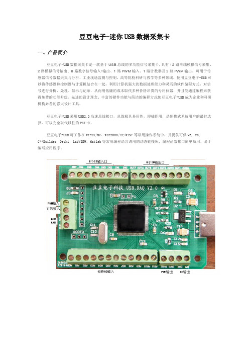
豆豆电子-迷你USB数据采集卡一、产品简介豆豆电子-USB数据采集卡是一款基于USB总线的多功能信号采集卡,具有12路单端模拟信号采集、2路模拟信号输出、8路数字信号输入/输出、1路PWM输入、1路计数器及2路PWM输出。
可用于传感器信号数据采集与分析、工业现场监测与控制、高等院校科研与教学等多种领域。
使用豆豆电子-USB可以将传感器和控制器与计算机结合在一起,利用计算机强大的数据处理能力和灵活的软件编程方式,对信号进行分析、处理、显示与记录,从而用低廉的成本取代多种价格昂贵的专用仪器,并且能通过编程来获得免费的功能升级。
先进的设计理念、丰富的硬件功能与简洁的编程方式使豆豆电子-USB成为企业和科研机构必备的强大设计工具。
豆豆电子-USB采用USB2.0高速总线接口,总线极具易用性,即插即用,是便携式系统用户的最佳选择,可以完全取代以往的PCI卡。
豆豆电子-USB可工作在Win9X/Me、Win2000/XP/WIN7等常用操作系统中,并提供可供VB, VC,C++Builder, Dephi,LabVIEW,Matlab等常用编程语言调用的动态链接库,编程函数接口简单易用,易于编写应用程序。
单位:mm二、性能指标2.1、USB总线性能●USB2.0高速总线传输●使用方便,能够实现自动配置,支持设备的热插拔即插即用2.2、模拟信号输入●模拟输入通道: 12路单端●输入端口耐压: 0—3.3V●输入信号量程: 0—3.3V●模拟输入阻抗: 10M●分辨率: 12Bit(4096)●最大总误差: < 0.2%●采样时钟: 100sps-100Ksps内部时钟(多通道50K)2.3、模拟信号输出●模拟输出通道: 2路单端(同步)●模拟输出范围: 0-3.3V●模拟输出电流: 1毫安●分辨率: 12Bit(4096)●非线性误差: ±2LSB●扫描时钟: 1sps-1000Ksps内部时钟2.4、数字信号输入/输出●输入/输出通道: 8路●输入/输出模式: 全输入/全输出●输入电平: 兼容TTL或CMOS●输出电平: CMOS2.5、PWM测量输入●个数: 1●输入电压: 0-3.3V●输入频率: 1—1MHz●输入占空比: 1%--99%●频率及占空比测量误差:1%2.6、计数器●计数器个数: 1●输入电平: TTL或CMOS●计数位: 32位(最大65535*65535)2.7、PWM输出●PWM输出通道: 2●PWM输出电平: CMOS●输入占空比:1%--99%●输出频率:1—1MHz2.8、工作温度●0℃ - 70℃三、应用领域便携式仪表和测试设备传感器信号采集与分析工业控制四、软件支持提供Windows95/98/NT/2000/XP/WINDOWS 7(32bit)下的驱动程序,提供通用DLL文件,并提供在LabVIEW和LabWindows图像化语言编写的应用软件范例程序。
DC-USB-PM1 USB到并行打印机线缆说明书
USB to PARALLEL PRINTER CABLEManualDC-USB-PM1IntroductionsThe USB to parallel printer cable allows your PC to print to most parallel printerdevice connected through the USB port. Just plug the USB connector of the cableinto the USB port of your PC and the other end into the Centronics connector of the parallel printer. USB (Universal Serial Bus) interface provides up to 12Mbps data throughput, so printing is much faster compared when connected to standardparallel port (150kbs). The USB-Parallel cable also provides true plug-n-play andhot-plug capability – simply plug in the cable under the Windows operating systemand the cable will be instantly detected.Specifications & FeaturesSingle chip (ASIC) USB to Parallel communicationWindows 98 and Windows Me Driver SupportUniversal Serial Bus Specification Rev. 1.1 compliantUSB full speed communication and bus poweredUSB Printer Class Specification 1.0 compliantIEEE-1284 1994 (bi-directional parallel interface) specification compliantProduct connection diagram (Application)AttentionsYou need to install the driver under Windows98.1. Power on your computer and make sure that the USB port is enabled and working properly.2. Plug in the USB-Parallel cable into the USB port and Windows will detect the IEEE-1284 device and run the Add New Hardware Wizard to assist youin setting up the new device.3. Plug in the USB-Parallel cable into the USB port and Windows7.0/8.0/8.1/XP will detect the device and installing the USB PRINTING SUPPORT automatically.Setting Up the Printer Device (Windows 98)1. If you have already installed a printer device before, click Start, Settings, and Printers. Right-click the default installed printer and click on Properties. The Properties dialog box of the installed printer will appear on your screen.2. Click the Details folder tab and change the printer port to LPT2:(USB to Parallel Port).3. If you do not have a printer installed yet, click on Start, Settings, Printers, Add Printer. The Add Printer Wizard will start and assist you in installing a new printer device. Select the printer manufacturer and model name from the list provided by the wizard or use the printer driver diskette supplied with your printer.4. When prompted which port the printer will use, click on LPT2: USB to Parallel Port.Setting Up the Printer Device (windows7.0/8.0/8.1/XP)1. If you have already installed a printer device before, click Start, Settings, and Printers. Click right button of your mouse on the printer and click on PORTS to select the USB0.2. If you do not have a printer installed yet, click on Start, Settings, Printers, Add Printer. The Add Printer Wizard will start and assist you in installing a new printer device. Select the printer manufacturer and model name from the list provided by the wizard or use the printer driver diskette supplied with your printer.3. When prompted which port the printer will use, click on USB0.Printer Listcompany Printer modelHP HP DeskJet :1. DeskJet 420, DeskJet 500C, DeskJet 520C, DeskJet 670C,2. DeskJet 692C, DeskJet 695C, DeskJet 710C, DeskJet 750,3. DeskJet 850C, DeskJet 870C, DeskJet 890C, DeskJet 895,4. DeskJet 1100C, DeskJet 1120CHP LaserJet :1. LaserJet III P, LaserJet 4, LaserJet 4 PLUS, LaserJet 4P,2. LaserJet 4L, LaserJet 4V, LaserJet 5P, LaserJet 5L,3. LaserJet 5M, LaserJet 6P, LaserJet 6L, LaserJet 1100A,4. LaserJet 2000C, LaserJet 2100M, LaserJet 4000, LaserJet 5000Epson Epson Stylus :1. Stylus Color 300, Stylus Color 400, Stylus Color 440, Stylus C42. Stylus Color 600, Stylus Color 740, Stylus Color 800, Stylus Color 850,3. Stylus Photo 700, Stylus Photo Ex ,Stylus Photo 790 , Stylus Photo 810Epson PM :1. PM-700C, PM-750C, PM-2000CEpson EPL :1. EPL-N1600 , LQ-300K , LQ-300K+, EPL-6200L,Canon Canon BJC :1. BJC-30, BJC-50, BJC-70, BJC-80, BJC-200, BJC-200ex,2. BJC-210, BJC-210sp, BJC-230, BJC-240, BJC-250,3. BJC-255sp, BJC-4000, BJC-4100, BJC-4200sp, BJC-4300,4. BJC 4650, BJC-6000, BJC 70005.PIXUS 560iLexmark Lexmark :1. XJ-350, 1100, Z11Panasonic Panasonic : 1. KX-1121Brother Brother:1. HL-5250DN LaserSamsung Samsung: 1.ML-2250。
USB视频采集卡使用说明书
其余三个 口均不接
2.测试线和采集卡的连接方法 测试线莲花头一端接在 USB 视频采集卡的黄色端子,另一端有 2 头
出线,分别是信号线(接 VTO)和地线,注意:测试线有 2 个出头,连 接时需要用万用表测一下导通;其中和莲花头外壳导通的接 GND,和 莲花头中心导通的接 VTO。
产品特性
◎ 支持 USB2.0,无需打开机箱,支持热插拔,支持笔记本电脑 ◎ 自行调整画面大小、最高分辨率可达 720×576,24 位真彩色 ◎ 最新技术 USB AUDIO、立体声输入输出 ◎ 图像亮度、对比度、饱和度、色度可自定义 ◎ 可捕捉高品质动态及静态画面,采集画面顺畅不间断 ◎ 输入接口有 AV 及 S 端子,可在台式机或手提电脑上观看录像、VCD、 DVD、摄像机等设备输出的视频影象 ◎ 支持 MPEG1/2 等多种实时压缩格式,方便制作 VCD/SVCD/DVD ◎ 兼容 WINDOW XP/Win7,兼容 Direct8.1、9.0
即在属性对话框中的 Image 标签下,选择“PAL/M”和“组合”选项, 确定后,即可在显示区看到摄像头图像了;如果此时还没有图像显示, 请调到第二步检查电气连接是否正确。
2.《USB 视频采集卡-Win7 版》
第一步 打开文件包,点击 Setup,进行软件安装。一直点击下 一步进行安装。
安装完成后,在桌面上回生成如下图所示的图标
插好 USB 视频采集卡,打开软件。如果 USB 视频采集卡没有插好, 或者 USB 口驱动电流不足,或者 USB 口接触松动,打开软件的时候会 出现以下错误:
更换 USB 口或者重新拔插几次,就可以打开软件了。如果重复几 次不可以打开软件,那么重新启动系统或者调到第三步重新安装软件 和驱动。
USB-HUB配合安卓一体机使用说明书

USB-HUB配合安卓一体机使用说明书USB-HUB外观图
与驱动板连接接线图
住:USB-HUB上PC/DB口对应安卓驱动板上的RXD2口,
USB-HUB上PC/ON口对应安卓驱动板上的TXD2口,
USB-HUB上pcDE口对应安卓驱动板上的SYNC口。
主要功能说明:
1.触摸屏可在安卓主板和电脑间随意切换
电视功能菜单内有项触摸屏设置的功能。
为安卓时触摸屏总在安卓主板上。
为电脑时触摸屏总在电脑上。
为自动(默认值)时,当切换到HDMI4通道时(没有就切换到HDMI3)触摸屏就会自动切换到电脑上,当切换到安卓桌面时触摸屏就会自动切换到安卓主板上。
按键板的K7键可以实现HDMI4通道(没有就为HDMI3)与安卓桌面的相互切换。
2.为安卓主板添加了三个UBS接口
USB(A,B,C)口,为安卓主板专用HUB功能,不能切换到PC。
B (D) 为触摸屏USB输出专用接口
它没有USB输入功能,没有电源输出功能。
直接连接外部电脑时触摸屏会自动切换到电脑上。
4.可侦测和控制电脑开关机
此功能UBS-HUB线路接法有点不同,程序也不一样。
LMC-PCIE-V6K3-SPI 系列激光控制卡 电气使用说明书
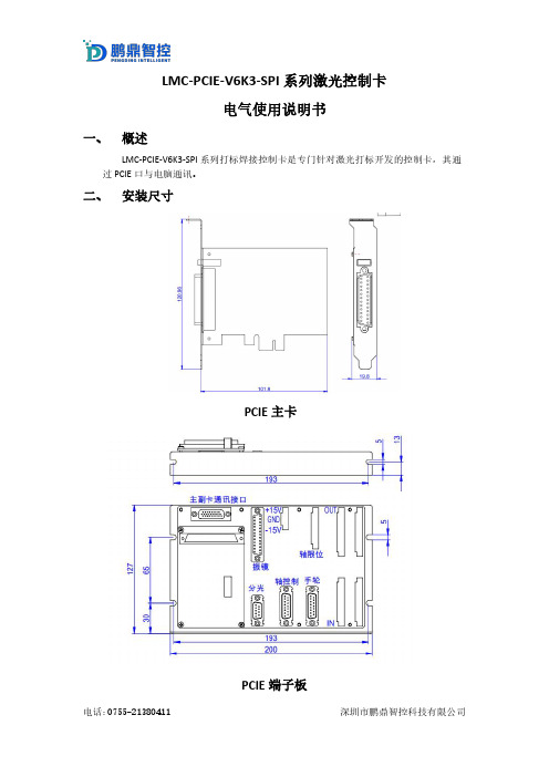
LMC-PCIE-V6K3-SPI系列激光控制卡电气使用说明书一、概述LMC-PCIE-V6K3-SPI系列打标焊接控制卡是专门针对激光打标开发的控制卡,其通过PCIE口与电脑通讯。
二、安装尺寸PCIE主卡PCIE端子板三、外观介绍PCIE主卡PCIE端子板四、LED指示灯说明注意:在对控制卡上电后第一时间查看亮灯情况,如果异常马上断电检查接线情况。
主卡灯状态:位号说明状态三色灯绿色指示灯空闲灯黄色指示灯运行灯红色指示灯报警灯端子板灯状态位号说明LED1负向电源指示灯LED6正向电源指示灯LED8外接24V电源指示灯(IO)LED3板卡空闲指示灯LED4板卡工作中指示灯LED5板卡错误指示灯五、接口说明5.1电源接口(J1,3PIN接线端子)5.1.1振镜不通过板卡J1端口供电接线方式管脚号板卡端丝印名称方向供电电源电压电源功率1+15V输入8V~28V>5W2GND输入GND3-15V不接注:如是以上方式接线,为避免振镜或板卡损坏需将振镜电源参考地与板卡电源参考地短接。
5.1.2振镜通过板卡J1端口供电接线方式管脚号板卡端丝印名称方向供电电源电压电源功率供电线径1+15V输入振镜正向电源电压(8~28V范围内)振镜功率+5W不小于0.75平方mm2GND输入GND振镜功率+5W不小于0.75平方mm 3-15V输入振镜负向电源电压(-8~-28V范围内)振镜功率+5W不小于0.75平方mm例如:鹏鼎Ⅰ、Ⅱ代振镜供电,J1端口如下接线:管脚号板卡端丝印名称方向供电电源电压电源功率供电线径1+15V输入+15V振镜功率+5W不小于0.75平方mm 2GND输入GND振镜功率+5W不小于0.75平方mm 3-15V输入-15V振镜功率+5W不小于0.75平方mm管脚号板卡端丝印名称方向供电电源电压电源功率供电线径1+15V输入+24V振镜功率+5W不小于0.75平方mm 2GND输入GND振镜功率+5W不小于0.75平方mm 3-15V输入不接5.2振镜控制接口定义(J3,DB25母头)(XY2-100协议接口定义)管脚名称说明信号方向管脚名称说明信号方向1Clk-时钟信号-输出14Clk+时钟信号+输出2Sync-同步信号-输出15Sync+同步信号+输出3X_data-X振镜信号-输出16X_data+X振镜信号+输出4Y_data-Y振镜信号-输出17Y_data+Y振镜信号+输出5X_fb-(A-)X振镜反馈-(复用,飞行A-)输入18X_fb+(A+)X振镜反馈+(复用,飞行A+)输入6Y_fb-(B-)Y振镜反馈-(复用,飞行B-)输入19Y_fb+(B+)Y振镜反馈+(复用,飞行B+)输入9/10 /22+15V振镜供电电源+15V输出,与J1的1脚直连11/23/24GND GND,电源参考点输出,与J1的2脚直连12/1 3/25-15V振镜供电电源-15V输出,与J1的3脚直连7/8/20/21NC留用5.2.1振镜控制接口(J3,DB25母头)(SL2-100协议接口定义)振镜接线(SL2-100)SCANLAB振镜接口控制卡振镜接口振镜管脚号振镜信号定义控制卡管脚号接口定义1DATA IN+16x-data+6DATA IN-3X-data-5DATA OUT+18X-FB+9DATA OUT-5X-FB-7,8GND11,23,24GND注:①振镜信号(+,-)为一对差分信号,信号线要用屏蔽双绞线,振镜信号线长度<20m.②如果振镜电源从J3供电,供电线缆线径不小于0.75平方mm。
- 1、下载文档前请自行甄别文档内容的完整性,平台不提供额外的编辑、内容补充、找答案等附加服务。
- 2、"仅部分预览"的文档,不可在线预览部分如存在完整性等问题,可反馈申请退款(可完整预览的文档不适用该条件!)。
- 3、如文档侵犯您的权益,请联系客服反馈,我们会尽快为您处理(人工客服工作时间:9:00-18:30)。
USBLMC_CUH_IPG_V1(3)USBLMC 用户使用手册IPG YLP系列激光器专用版本记录版本号更新日期更新人更新说明V1.0 2007-1V1.1 2007-6V1.2 2008-5V1.3 2008-5-12 吕文杰同时兼容B型/D型接口的YLP 系列激光器;电源连接方案改变目录安全须知 (1)一、概述 (2)1.1 如何辨识IPG YLP 激光器专用控制卡 (2)1.2 主要特点 (3)1.1 版本说明 (3)二、电气连接 (3)2.1接口说明 (3)2.1.1电源 (3)2.1.2 CON1 :DB15 振镜控制 (4)2.1.3 CON2 :DB25 激光控制 (5)2.1.4 CON3 :DB9飞标接口 (6)2.1.5 CON4:DB15 电源/IO 插座 (7)2.1.6 CON5:IDC10 IO 插座 (8)2.2 跳线说明 (9)2.3 数字输入输出信号的连接 (10)2.3.1输入信号 In4,In8, Start,EMSTOP (10)2.3.1输入信号 In5,In9 (11)2.4 电源的连接 (12)2.5 典型连接 (13)安全须知在安装、使用USBLMC控制卡之前,请仔细阅读本节内容。
若有任何关于本文档的疑问,请联系BJJCZ。
1. 安全操作步骤请遵守所有的关于激光的安全说明(包括但不仅限于描述于激光器、振镜以及本文档中的相关章节)无论任何时候,请在开启了电脑电源、USBLMC电源及振镜电源之后再打开激光器电源。
否则,可能会因不可控的激光光束而造成伤害。
我们建议您使用光闸来避免不可控的激光造成的伤害。
2. 客户负责的安全部分USBLMC被设计用来控制一个激光扫描系统。
因此,所有有关激光系统的安全指示都应该被客户了解并施行。
客户必须严格遵守相关的安全操作指示并独立地负责所用的激光系统的安全。
安全规则可能因国家不同而有所差异。
客户有责任遵守当地的所有规定。
在运行软件之前请仔细检查。
软件错误有可能导致系统停止响应。
在此情况下,振镜及激光均不可控制。
请避免板卡受到潮湿、灰尘、腐蚀物及外物撞击的损坏。
在储存及使用板卡时,请避免电磁场及静电的损坏。
它们有可能损毁板卡上的电子器件。
请使用防静电包装袋储存板卡;请佩戴接地良好的防静电防护手套接触板卡。
请保证板卡储存在摄氏-20℃至+60℃的环境下。
允许的工作环境温度为25℃±10℃。
一、概述USBLMC打标控制卡是针对激光打标机而专门开发的控制卡,采用USB接口与PC机相连。
USBLMC打标控制卡根据设备所使用的激光器分为几种类型。
对于采用 IPG YLP系列激光器的激光打标机,使用本型号的控制卡,以获得最佳的控制效果。
1.1 如何辨识IPG YLP 激光器专用控制卡板卡中间位置印有“To IPG-YLP Fiber Laser Module”字样;在板卡的右下角印有“MODEL: FIBER IO”字样,如图 1-1 所示。
图 1-1 IPG-YLP 系列激光器专用控制卡示意图其中,CON1:振镜(SCANHEAD)控制接口, DB15插座CON2:IPG YLP 系列激光器的DB25控制接口;CON3:飞标(Mark on fly)接口,用于连接编码器,DB9插座;CON4:IO接口,用于连接电源以及控制信号,DB15插座。
CON5:IO接口,用于连接控制信号,10 针IDC插座。
(注:V3 版本的控制卡才有)1.2 主要特点采用DB25插座输出激光控制信号,与 IPG YLP系列激光器通过25针电缆直连。
振镜控制信号为数字信号,可直接连接国际上通用的数字振镜。
飞行打标:可连接旋转编码器,实时检测流水线的速度,保证高速打标效果。
支持单机多卡工作模式。
一台电脑可以同时控制 8 套USBLMC打标控制卡并行操作。
8 套控制卡可以加工不同的内容。
扩展轴(步进电机/伺服电机)输出:可输出一个通道的方向/脉冲信号控制步进电机(或伺服电机),可用于转轴或者拼接。
4 路通用输入数字信号(TTL 兼容)。
In4,In5,In8,In9。
其中,In4 从CON4 插座接入;In5 从CON5 插座接入;In8/In9 从CON3 插座接入5 路通用输出数字信号(TTL 兼容)。
Out0/1/4/5/6。
其中,Out0 从CON4 插座输出;Out1/4/5/6 从CON5 插座输出Start(开始)信号:用于打标内容相同,要求高速打标的情况。
脚踏开关可以连接至 Start 信号,也可以连接至通用输入信号。
如果打标内容含有变量文本,或者打标内容较多无法全部保存在板卡中,必需连接至通用输入信号。
兼容 USB2.0。
1.1 版本说明板卡的右下角标注为“REV:20070716-2 ”,即V2 版本的控制卡只能用于控制 B 型接口的激光器;板卡的右下角标注为“REV:20080425-3 ”,即V3 版本的控制卡用于控制 D 型接口的激光器,能兼容B 型接口的激光器。
控制卡\激光器B型接口激光器D型接口激光器版本 REV:20070716-2 支持不支持版本 REV:20080425-3 支持支持注:目前大陆地区主要为B型接口激光器。
二、电气连接2.1接口说明2.1.1电源控制卡需要 5V 直流电源供电。
建议采用 5V/3A 的直流电源。
电源从CON4 插座的4/5/12/13 管脚接入。
CON4管脚名称说明4, 5 VCC +5V。
电源的正极性端。
12,13 GND 地。
电源的负极性端。
2.1.2 CON1 :DB15 振镜控制振镜控制信号为数字信号,可以直接连接至数字振镜。
由于数字振镜所用的数字信号传输协议不完全一样,所以,需要确认是数字振镜使用何种传输协议。
我公司也提供了数字转模拟的转接板,也可通过该转换板转成模拟信号输出连接到模拟振镜。
图 2-1 CON1 插座管脚定义示意图管脚名称说明1,9 CLK- / CLK+时钟信号- / 时钟信号+2,10 SYNC- / SYNC+同步信号- / 同步信号+Channel-/ X Channel+振镜X信号- / 振镜X信号+3,11 XChannel- / Y Channel+振镜Y信号-/振镜Y信号+4,12 YChannel-/ Z Channel+振镜Z信号-/振镜Z信号+5,13 Z6,14, Status-/Status+ 保留7 NULL 保留8,15 GND 地对于常用的二维振镜,只需要连接 CLK 时钟、SYNC同步、XChannel、Ychannel 四组信号共八根信号线即可。
数字信号建议采用带屏蔽层的双绞线连接。
2.1.3 CON2 :DB25 激光控制CON2 插座与光纤激光器的 25 针插座通过25针排线直接对接。
图2-2 CON2 插座管脚定义示意图管脚号信号名称说明1——8 P0——P7 激光器功率。
TTL 输出。
9 PLATCH 功率锁存信号。
TTL 输出。
10, 14,Gnd 控制卡的参考地。
V2版本:Gnd 控制卡的参考地。
11,12V3版本:SGIN2,SGIN3激光器的状态输入。
V2版本:Gnd 控制卡的参考地。
13,15,24V3版本:NULL 此脚悬空,不连接。
16,21 SGIN0,SGIN1 激光器的状态输入。
17 Vcc 控制卡的5V 电源输出。
18 MO 主振荡器开关信号。
TTL 输出。
19 AP 功率放大器开关信号。
TTL 输出。
20 PRR 重复脉冲频率信号。
TTL 输出。
22 Out2 激光器的红光指示信号。
TTL 输出。
23 EMSTOP 急停开关信号。
TTL 输出。
25 此脚悬空,不连接。
2.1.4 CON3 :DB9飞标接口图 2-3 CON3 插座管脚定义示意图管脚名称说明1 IN8 输入端口8 与GND组成回路2,6 IN9+,IN9-输入端口9 IN9内部有1K限流电阻;如果电压高于12V,建议外接限流电阻3,7 BCODEP/BCODEN 编码器输入B+/B-4,5 ACODEP/ACODEN 编码器输入A+/ A-8 VCC +5V输出与9脚形成回路9 GND 地2.1.5 CON4:DB15 电源/IO 插座图 2-4 CON4 插座管脚定义示意图管脚号信号名称说明1 SGIN4 通用输入信号4。
与控制卡的地(12,13脚)组成回路。
使用此信号时,将此信号与地分别连接至开关的两端即可。
本信号为输入信号。
2 EMSTOP 紧急停止信号。
与控制卡的地(12,13脚)组成回路。
使用此信号时,将此信号与地信号分别连接至常开型开关的两端即可。
按下开关时表示意外情况发生,立即停止操作。
本信号为输入信号。
V2版本:POW_BTN 激光器主电源的电源开关信号。
与控制卡的地(12,13脚)组成回路。
使用此信号时,将此信号与地信号分别连接至常开型开关的两端即可。
按下开关时,10,11 脚连通;开关弹起时,10,11脚断开。
本信号为输入信号。
3V3版本:NULL 不连接4,5 VCC 5V输入电源的正极性端。
本信号为输入信号。
12,13 Gnd 5V 输入电源的负极性端(地信号),即控制卡的地信号。
本信号为输入信号。
8 START 开始信号。
与控制卡的地(12,13脚)组成回路。
使用此信号时,将此信号与地分别连接至开关的两端即可。
本信号为输入信号。
9 OUT0 通用输出信号0。
以 12,13 脚的 Gnd 信号作为参考地。
本信号为输出信号。
V2版本:POW_CON,POW_CON1 电源继电器的连接端子。
将POW_CON 连接至电源继电器的控制电源的正端;电源继电器的两个控制端,一边接POW_CON1,另一边接电源继电器的控制电源的负端。
当3脚电源开关按下时, POW_CON ,POW_CON1 连通,此时,电源继电器的控制端连接到其控制电源上,继电器吸合,光纤激光器主电源上电。
10,11 V3版本:NULL 不连接 6,14 DIR-/DIR+ 输出信号。
扩展轴(步进电机或伺服电机)的方向信号,输出方式可以设置为差分输出或者共阳输出(TTL 输出)。
本信号为输出信号。
7,15 PUL-/PUL+扩展轴(步进电机或伺服电机)的脉冲信号,输出方式可以设置为差分输出或者共阳输出(TTL 输出)。
本信号为输出信号。
2.1.6 CON5:IDC10 IO 插座图 2-5 CON5 插座管脚定义示意图管脚号 信号名称 说明1,2,3,4 OUT5/4/6/1 通用输出信号1/4/5/6。
以 5,7脚的 Gnd 信号作为参考地。
本信号为输出信号。
5,7 GND 地6,8 Null不使用 9,10S45GND, SGIN5 通用输入信号5的正/负端2.2 跳线说明图2-6 光纤接口板跳线位置示意图注:V3 版本已经去除 JP3/JP4。