11-21-BHC-AQ2S1M-2T中文资料
SC221资料
元器件交易网
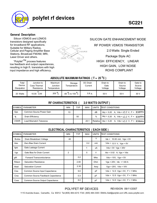
SC221
POUT VS PIN GRAPH
SC221 Pout/Gain vs Pin Freq=850Mhz, Vds=12.5Vdc, Idq=.2A
13.00 3.2 P1dB = 2.3 watts 2.8 2.4 2 1.6 1.2 Efficiency@2.5W = 56% 0.8 0.4 0 0 0.1 0.2 0.3 PIN IN WATTS 0.4 8.00 0.5
850MHz 850 MHz 850MHz
η
VSWR
ELECTRICAL CHARACTERISTICS ( EACH SIDE )
SYMBOL PARAMETER Bvdss Idss Igss Vgs gM Rdson Idsat Ciss Crss Coss Drain Breakdown Voltage Zero Bias Drain Current Gate Leakage Current Gate Bias for Drain Current Forward Transconductance Saturation Resistance Saturation Current Common Source Input Capacitance Common Source Feedback Capacitance Common Source Output Capacitance 2 0.2 2.00 2.30 9.0 0.3 8.0 MIN 40 0.2 1 5 TYP MAX UNITS TEST CONDITIONS V mA uA V Mho Ohm Amp pF pF pF Ids = 10.00 mA, Vgs = 0V Vds = 12.5 V, Vgs = 0V Vds = 0V Vgs = 30V Ids = 0.02 A, Vgs = Vds Vds = 10V, Vgs = 5V Vgs = 20V, Ids = 1.60 A Vgs = 20V, Vds = 10V Vds = 12.5 Vgs = 0V, F = 1 MHz Vds = 12.5 Vgs = 0V, F = 1 MHz Vds = 12.5 Vgs = 0V, F = 1 MHz
三位一体电气双向阀门产品参数说明书

VISIT OUR WEBSITES: • • .auSeries 3ABVAutomated Ball Valve - 3-Way Brass NPTElectric and Pneumatic ActuatorsSPECIFICATIONSService:Compatible liquids, gases or steam.Body:3-way.Line Size:1/4˝ to 2˝.End Connections:Female NPT.Pressure Limits:1/4˝ to 1-1/4˝: 435 psi (30 bar) WOG; 1-1/2˝: 232 psi (16 bar)WOG; 2˝: 145 psi (10 bar) WOG. 100 psi (6.9 bar) SWP .Wetted Materials:Body, end cap, stem:Brass; Ball: Brass, chrome plated; Seat,stem seal: TFE.Temperature Limits:320°F (160°C).Other Materials:Body seal, body O-ring, stem O-ring: Fluoroelastomer.ACTUATORS Electric Power Requirements: 120 VAC, 50/60Hz, single phase. Optional 220 VAC, 24VAC, 12 VDC, and 24 VDC.Power Consumption (Locked Rotor Current):Two position: 1/4˝ to 3/4˝: .55A,1˝ to 2˝: .75A; Modulating: 1/4˝ to 3/4˝:.55A, 1˝ to 2˝: .75A.Cycle Time:(per 90°): Two position: 1/4˝to 3/4˝: 2.5 sec., 1˝ to 2˝: 5 sec.;Modulating: 1/4˝ to 3/4˝: 2.5 sec., 1˝ to 2˝:5 sec.Duty Cycle:Two position: 1/4˝ to 3/4˝:75%, 1˝ to 2˝: 25%; Modulating: 75%.Enclosure Rating:NEMA 4. Optional NEMA 7.Housing Material: Aluminum with thermal bonding polyester powder finish.Temperature Limit:0 to 150°F (-18 to 65°C).Conduit Connection:1/2˝ female NPT.Modulating Input:4 to 20 mA.Standard Features:Manual override and visual position indicator except modulating units.Pneumatic “DA” and “SR” SeriesType: DA series is double acting and SR series is spring return (rack and pinion).Normal Supply Pressure:80 psi (5.5 bar).Maximum Supply Pressure:120 psig (8 bar).Air Connections:DA/SR1 to 5: 1/8˝ female NPT, all other sizes: 1/4˝ femaleNPT.Air Consumption:(per stroke) DA1:2.32 cu. in.; DA2, SR2: 9.34 cu. in.; DA3,SR3: 17.21 cu. in.; DA4, SR4: 20.5 cu.in.; SR5: 39.54 cu. in. Cycle Time: (per 90°) DA1: .03 sec.;DA2: .04 sec.; DA3: .08 sec.; DA4: .12sec.; SR2: .09 sec.; SR3: .14 sec.; SR4:.22 sec.; SR5: .33 sec.Housing Material:Anodized aluminum body and epoxy coated aluminum end caps.Temperature Limit:-4 to 180°F (-20 to 82°C).Accessory Mounting: NAMUR standard.Standard Features:Visual position indicator.The Series 3ABV incorporates a standard port valve for great flow rates with minimalpressure drop. Features include a blowout proof stem for added safety and reinforced TFE seats and seals for longer life and leak-free operation. The four seat design allows for high cyclic capabilities and tight shut-off in any position. Perfect for mixing or diverting services in the food and chemical processing industries.The 3ABV is an economical automated valve package with either an electric or pneumatic actuator. Electrically actuated models are weatherproof, NEMA 4, powered by standard 115VAC supply, and are available in either two-position or proportional control. Two-position actuators use the 115 VAC input to drive each of the valve ports open or closed, while the modulating actuator accepts a 4-20 mA input for infinite valve positioning. Actuator features include thermal overload protection to withstand stall conditions, visual position indication,and a permanently lubricated gear train.The pneumatic double acting actuator uses an air supply to drive each of the actuator ports.Spring return pneumatic actuators use the air supply to drive the valve stem in one direction,and internally loaded springs return the valve to its original position. Also available is the SV3 solenoid valve to electrically switch the supply pressure between the air supply ports.Actuators are constructed of anodized aluminum and are epoxy coated for years of corrosion free service.How To Order:1. Select Model No.to specify pipe size and actuator.2. Choose a Port Configuration to determine valve flow path.Example:3ABV1DA204-T2Optional Electric Actuator Supply Voltages-Contact factory for model number changeSolenoid Valve -See Model SV3.。
12-21-BHC-AN1P2-2C
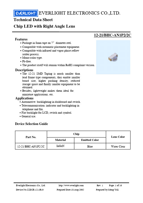
EVERLIGHT ELECTRONICS CO.,LTD.Technical Data Sheet Chip LED with Right Angle Lens12-21/BHC-AN1P2/2CFeatures․Package in 8mm tape on 7〞diameter reel. ․Compatible with automatic placement equipment. ․Compatible with infrared and vapor phase reflow solder process. ․Mono-color type. ․Pb-free. ․The product itself will remain within RoHS complaint version.Descriptions․The 12-21 SMD Taping is much smaller than lead frame type components, thus enable smaller board size, higher packing density, reduced storage space and finally smaller equipment to be obtained. ․Besides, lightweight makes them ideal for miniature applications. etc.Applications․Automotive: backlighting in dashboard and switch. ․Telecommunication: indicator and backlighting in telephone and fax. ․Flat backlight for LCD, switch and symbol. ․General use.Device Selection GuideChip Part No. 12-21/BHC-AN1P2/2C Material InGaN Emitted Color Blue Water ClearLens ColorEverlight Electronics Co., Ltd. Device No.SZDSE-121-B10 Prepared Date:18-Aug-2005Rev. 1Page: 1 of 10Prepared by:Meng YaliEVERLIGHT ELECTRONICS CO.,LTD.12-21/BHC-AN1P2/2CPackage Outline DimensionsNote: The tolerances unless mentioned is ±0.1mm ,Unit = mmEverlight Electronics Co., Ltd. Device No. :SZDSE-121-B10 Prepared date:19-Aug-2005Rev. 1Page: 2 of 10Prepared by:Meng YaliEVERLIGHT ELECTRONICS CO.,LTD.12-21/BHC-AN1P2/2CAbsolute Maximum Ratings (Ta=25℃) ParameterReverse Voltage Forward Current Operating Temperature Storage Temperature Electrostatic Discharge(HBM) Power Dissipation Peak Forward Current (Duty 1/10 @1KHz) Soldering TemperatureSymbolVR IF Topr Tstg ESD Pd IFPRating5 25 -40 ~ +85 -40 ~ +90 150 110 100UnitV mA ℃ ℃ V mW mATsolReflow Soldering : 260 ℃ for 10 sec. Hand Soldering : 350 ℃ for 3 sec.Electro-Optical Characteristics (Ta=25℃) ParameterLuminous Intensity Peak Wavelength Dominant Wavelength Spectrum Radiation Bandwidth Viewing Angle Forward Voltage Reverse CurrentSymbolIV λp λd △λ 2θ1/2 VF IRMin.28.5 ---464.5 -------------Typ.----468 ---35 120 3.5 ----Max.72.0 ---476.5 ------4.3 10Unitmcd nm nmConditionIF=20mA nm deg V μA VR=5VNotes:1.Tolerance of Luminous Intensity ±10% 2.Tolerance of Dominant Wavelength ±1nm 3.Tolerance of Forward Voltage ±0.1VEverlight Electronics Co., Ltd. Device No. :SZDSE-121-B10 Prepared date:19-Aug-2005 Rev. 1 Page: 3 of 10Prepared by:Meng YaliEVERLIGHT ELECTRONICS CO.,LTD.12-21/BHC-AN1P2/2CBin Range Of Dom. WavelengthGroup Bin A9 A10 A11 A12 Min 464.5 467.5 470.5 473.5 Max 467.5 470.5 473.5 476.5 nm IF=20mA Unit ConditionABin Range Of Luminous IntensityBin N1 N2 P1 P2 Min 28.5 36.0 45.0 57.0 Max 36.0 45.0 57.0 72.0 mcd IF=20mA Unit ConditionNotes:1.Tolerance of Luminous Intensity ±10% 2.Tolerance of Dominant Wavelength ±1nmEverlight Electronics Co., Ltd. Device No. :SZDSE-121-B10 Prepared date:19-Aug-2005Rev. 1Page: 4 of 10Prepared by:Meng YaliEVERLIGHT ELECTRONICS CO.,LTD.12-21/BHC-AN1P2/2CTypical Electro-Optical Characteristics CurvesEverlight Electronics Co., Ltd. Device No. :SZDSE-121-B10 Prepared date:19-Aug-2005Rev. 1Page: 5 of 10Prepared by:Meng YaliEVERLIGHT ELECTRONICS CO.,LTD.12-21/BHC-AN1P2/2CLabel explanationCAT: Luminous Intensity Rank HUE: Dom. Wavelength Rank REF: Forward Voltage Rankxxxxxx xxxxxxRoHSxxxxxxxxxxxx xxxx xxxxxxxxReel DimensionsNote: The tolerances unless mentioned is ±0.1mm ,Unit = mmEverlight Electronics Co., Ltd. Device No. :SZDSE-121-B10 Prepared date:19-Aug-2005Rev. 1Page: 6 of 10Prepared by:Meng YaliEVERLIGHT ELECTRONICS CO.,LTD.12-21/BHC-AN1P2/2CCarrier Tape Dimensions: Loaded quantity 2000 PCS per reelNote: The tolerances unless mentioned is ±0.1mm ,Unit = mmMoisture Resistant PackagingLabelAluminum moisture-proof bagDesiccantLabelEverlight Electronics Co., Ltd. Device No. :SZDSE-121-B10 Prepared date:19-Aug-2005Rev. 1Page: 7 of 10Prepared by:Meng YaliEVERLIGHT ELECTRONICS CO.,LTD.12-21/BHC-AN1P2/2CReliability Test Items And Conditions The reliability of products shall be satisfied with items listed below. Confidence level : 90 % LTPD : 10 % Test Sample No. Items Test Condition Ac/Rc Hours/Cycles Size Temp. : 260℃±5℃ 1 Reflow Soldering 22 PCS. 0/1 6 Min. Min5sec. 2 Temperature Cycle H : +100℃ 15min ∫ 5 min L : -40℃ 15min H : +100℃ 5min ∫ 10 sec L : -10℃ 5min Temp. : 100℃ Temp. : -40℃ IF = 20 mA 85℃/ 85% R.H 300 Cycles 22 PCS. 0/13 4 5 6 7Thermal Shock High Temperature Storage Low Temperature Storage DC Operating Life High Temperature / High Humidity300 Cycles 1000 Hrs. 1000 Hrs. 1000 Hrs. 1000 Hrs.22 PCS. 22 PCS. 22 PCS. 22 PCS. 22 PCS.0/1 0/1 0/1 0/1 0/1Everlight Electronics Co., Ltd. Device No. :SZDSE-121-B10 Prepared date:19-Aug-2005Rev. 1Page: 8 of 10Prepared by:Meng YaliEVERLIGHT ELECTRONICS CO.,LTD.12-21/BHC-AN1P2/2CPrecautions For Use1. Over-current-proof Customer must apply resistors for protection , otherwise slight voltage shift will cause big current change ( Burn out will happen ). 2. Storage 2.1 Do not open moisture proof bag before the products are ready to use. 2.2 Before opening the package, the LEDs should be kept at 30℃ or less and 90%RH or less. 2.3 The LEDs should be used within a year. 2.4 After opening the package, the LEDs should be kept at 30℃ or less and 60%RH or less. 2.5 The LEDs should be used within 168 hours (7 days) after opening the package. 2.6 If the moisture absorbent material (silica gel) has faded away or the LEDs have exceeded the storage time, baking treatment should be performed using the following conditions. Baking treatment : 60±5℃ for 24 hours. 3. Soldering Condition 3.1 Pb-free solder temperature profile3.2 Reflow soldering should not be done more than two times. 3.3 When soldering, do not put stress on the LEDs during heating. 3.4 After soldering, do not warp the circuit board.Everlight Electronics Co., Ltd. Device No. :SZDSE-121-B10 Prepared date:19-Aug-2005Rev. 1Page: 9 of 10Prepared by:Meng YaliEVERLIGHT ELECTRONICS CO.,LTD.12-21/BHC-AN1P2/2C4. Soldering Iron Each terminal is to go to the tip of soldering iron temperature less than 350℃ for 3 seconds within once in less than the soldering iron capacity 25W. Leave two seconds and more intervals, and do soldering of each terminal. Be careful because the damage of the product is often started at the time of the hand solder. 5.Repairing Repair should not be done after the LEDs have been soldered. When repairing is unavoidable, a double-head soldering iron should be used (as below figure). It should be confirmed beforehand whether the characteristics of the LEDs will or will not be damaged by repairing.EVERLIGHT ELECTRONICS CO., LTD. Office: No 25, Lane 76, Sec 3, Chung Yang Rd, Tucheng, Taipei 236, Taiwan, R.O.CTel: 886-2-2267-2000, 2267-9936 Fax: 886-2267-6244, 2267-6189, 2267-6306 Everlight Electronics Co., Ltd. Device No. :SZDSE-121-B10 Prepared date:19-Aug-2005Rev. 1Page: 10 of 10Prepared by:Meng Yali。
生物安全柜URS

XXXXXXXX股份有限公司Requirement Specification 用户需求说明书当前版本号:01设备名称:生物安全柜设备型号:BHC-1100ⅡA2数量:1台编制人: XXX 编制日期:设备名称:生物安全柜Equipment Name:制造商:Manufacturer:当前版本号:03文件编号:Document Number:第2页共9 页此表用于在本文件执行前的审核和批准;审核/批准部门/人员签字日期审核批准设备名称:生物安全柜Equipment Name:制造商:Manufacturer:当前版本号:03文件编号:Document Number:第3页共9 页目录1.总说明 (4)2.卖方的责任 (4)2.1 卖方的供货范围 (4)2.2 卖方的工作范围 (4)3. 供货界限 (4)4. 安装位置 (4)5. 性能参数 (4)6. 技术参数详述 (5)6.1 依据的标准和规范 (5)6.2 工作原理 (5)6.3 技术参数详述 (5)7. 电气设备 (6)8. 原材料、零部件和控制系统的可追溯性 (6)9. FAT工厂内验收测试 (6)9.1 FAT工作范围: (6)9.2确认及测试(包括但不限于以下内容)........................................................................................ (7)10. 包装、运输 (7)10.1 运输的准备 (7)10.2 运输 (7)11. SAT用户现场调试验收测试(包括但不限于) (7)11.1 测试和检查 (7)11.2 验证(所有验证项目由双方共同参与全过程,双方最后在验证文件上签字确认) (8)12. 文件资料 (8)12.1 文件格式 (8)12.2 提供文件的时间(进度)表 (8)13. 质量保证和责任 (9)14.售后服务和培训 (9)设备名称:生物安全柜Equipment Name:制造商:Manufacturer:当前版本号:03文件编号:Document Number:第4页共9 页1、总说明本文件的目的是制定XXXX股份有限公司采购生物安全柜的设计、生产、安装、测试和供应的要求。
DT12J11S2AQF中文资料
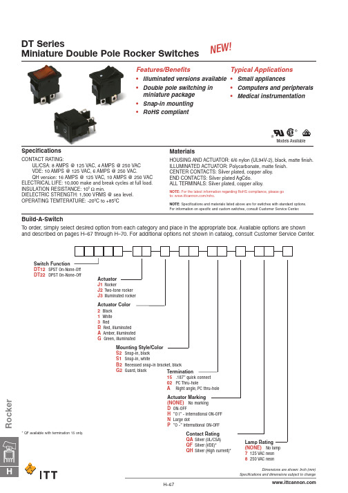
R o c k e rDT SeriesMiniature Double Pole Rocker SwitchesBuild-A-SwitchTo order, simply select desired option from each category and place in the appropriate box. Available options are shown and described on pages H–67 through H–70. For additional options not shown in catalog, consult Customer Service Center.SpecificationsCONTACT RATING:UL/CSA: 8 AMPS @ 125 VAC, 4 AMPS @ 250 VAC VDE: 10 AMPS @ 125 VAC, 6 AMPS @ 250 VAC.QH version: 16 AMPS @ 125 VAC, 10 AMPS @ 250 VAC ELECTRICAL LIFE: 10,000 make and break cycles at full load.INSULATION RESISTANCE: 108Ωmin.DIELECTRIC STRENGTH: 1,500 VRMS @ sea level.OPERATING TEMTERATURE: -20ºC to +85ºCMaterialsHOUSING AND ACTUATOR: 6/6 nylon (UL94V-2), black, matte finish.ILLUMINATED ACTUATOR: Polycarbonate, matte finish.CENTER CONTACTS: Silver plated, copper alloy.END CONTACTS: Silver plated AgCdo.ALL TERMINALS: Silver plated, copper alloy.NOTE:For the latest information regarding RoHS compliance, please go to: /rohs.NOTE : Specifications and materials listed above are for switches with standard options. For information on specific and custom switches, consult Customer Service Center.N E W !Models AvailableDT SeriesMiniature Double Pole Rocker SwitchesDimensions are shown: Inch (mm)Specifications and dimensions subject to changeRockerDimensions are shown: Inch (mm)Specifications and dimensions subject to changeR o c k e rDT SeriesMiniature Double Pole Rocker SwitchesS2SNAP-IN, BLACK S1SNAP-IN, WHITEB2RECESSED SNAP-IN BRACKET, BLACKG2GUARD, BLACKNOTE:Available with DT102 switch functions only.15.187” QUICK CONNECT02PC THRU-HOLENOTE:No VDE approval of this option..315(8,0).031(0,8).051(1,3).394(10,0).126(3,2).142(3,6)Dimensions are shown: Inch (mm)Specifications and dimensions subject to changeDT SeriesMiniature Double Pole Rocker Switches(NONE) NO LAMP 7125 VAC 33k ΩNEON 8250 VAC 150k ΩNEONNONENO MARKINGDON-OFFHO-lPO –NOTE:Orientation of actuator marking and terminals.ARIGHT ANGLE, PC THRU-HOLENOTE:No VDE approval of this option.Rocker。
螺纹标准表
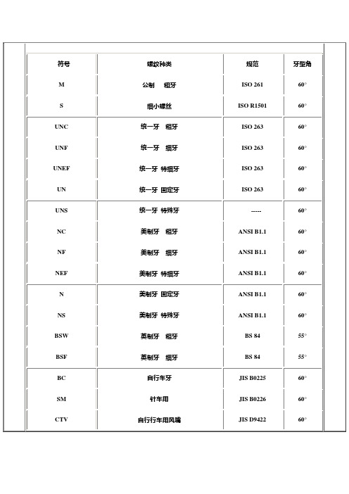
螺纹种类
规范
牙型角
M
公制粗牙
ISO 261
60°
S
细小螺丝
ISO R1501
60°
UNC
统一牙粗牙
ISO 263
60°
UNF
统一牙细牙
ISO 263
60°
UNEF
统一牙特细牙
ISO 263
60°
UN
统一牙固定牙
ISO 263
60°
UNS
统一牙特殊牙
-----
60°
NC
美制牙粗牙
ANSI B1.1
1-64UNC
5-44UNV
12-24UNC
3/8″-16UNC
1-72UNF
6-32UNC
12-28UNF
3/8″-24UNF
2-56UNC
6-40UNF
12-32UNEF
3/8″-32UNEF
2-64UNF
5/32″-32UNC
1/4″-20UNC
7/16″-14UNC
3-48UNC
8-32UNC
M11*1
M1.8*0.35
M4*0.5
M8*1
M11*1.5
M2*0.4
M4*0.7
M8*1.25
12*1
M2.2*0.45
M5*0.5
M9*1
M12*1.25
M2.3*0.45
M5*0.8
M9*1.25
M12*1.5
常用规格(美制)
0-80UNF
5-40UNC
10-32UNF
5/16″-32UNEF
NGT
美制瓦斯用推拔
ANSI B57.1
NTS-711通用保护测控装置说明书-V1.00
L玻璃仪器类

三、教育装备产品标准L玻璃仪器类序号标准编号标准名称备注1 GB 21549-2008 实验室玻璃仪器玻璃烧器的安全要求2 GB 21749-2008 教学仪器设备安全要求玻璃仪器及连接部件28 GB/T 6579-2007 实验室玻璃仪器热冲击和热冲击强度试验方法3 GB/T 11414-2007 实验室玻璃仪器瓶4 GB/T 12803-2015 实验室玻璃仪器量杯2016.7.1起实施;L00012量杯。
5 GB/T 12804-2011 实验室玻璃仪器量筒L00001量筒6 GB/T 12805-2011 实验室玻璃仪器滴定管L00041滴定管7 GB/T 12806-2011 实验室玻璃仪器单标线容量瓶L00021容量瓶8 GB/T 12807-1991 实验室玻璃仪器分度吸量管L00051移液管9 GB/T 12808-2015 实验室玻璃仪器单标线吸量管2016.7.1起实施。
10 GB/T 12809-2015 实验室玻璃仪器玻璃量器的设计和结构原则2016.7.1起实施。
11 GB/T 12810-1991 实验室玻璃仪器玻璃量器的容量校准和使用方法12 GB/T 14149-1993 实验室玻璃仪器互换球形磨砂接头13 GB/T 15723-1995 实验室玻璃仪器干燥器L20206干燥器14 GB/T 15724-2008 实验室玻璃仪器烧杯L10121烧杯15 GB/T 15725.4-1995 实验室玻璃仪器双口、三口球形圆底烧瓶L10152三口烧瓶16 GB/T 15725.6-1995 实验室玻璃仪器磨口烧瓶17 GB/T 15726-1995 玻璃仪器内应力检验方法18 GB/T 15727-1995 实验室仪器玻璃热冲击试验方法(棒状法)19 GB/T 21297-2007 实验室玻璃仪器互换锥形磨砂接头20 GB/T 21298-2007 实验室玻璃仪器试管L10101试管21 GB/T 21784.2-2008 实验室玻璃器皿通用型密度计第2部分:试验方法和使用22 GB/T 22067-2008 实验室玻璃仪器广口烧瓶23 GB/T 22362-2008 实验室玻璃仪器烧瓶L10131烧瓶、L10141锥形烧瓶、L10151蒸馏烧瓶。
FC21中文资料

Electrical Connection
B E/D S
C
80
G
ID -- VDS
[FET]
80
ID -- VDS
[FET]
Drain Current, ID -- mA
Drain Current, ID -- mA
60
VGS=0
--0.5V
--1.0V
60
VGS=0
--0.5V
40
40
--1.0V
100
ID -- VGS
[FET]
ID -- VGS
[FET]
VDS=10V
VDS=10V IDSS=60mA
Drain Current, ID -- mA
100
80
80
60
60
=7
5m
40
40
ID
40 m
20
Ta =
75
SS
55
--2
A
°C
20
0 --6 --5 --4 --3 --2 --1 0 ITR01963 --6 --5 --4 --3 --2 --1
SANYO Electric Co.,Ltd. Semiconductor Company
TOKYO OFFICE Tokyo Bldg., 1-10, 1 Chome, Ueno, Taito-ku, TOKYO, 110-8534 JAPAN
81001 TS IM TA-1526 No.7021-1/5
Parameter [FET] Drain-to-Source Voltage Gate-to-Drain Voltage Gate Current Drain Current Allowable Power Dissipation [TR] Collector-to-Base Voltage Collector-to-Emitter Voltage Emitter-to-Base Voltage Collector Current Collector Current(Pulse) Base Current Collector Dissipation [Common Ratings] Total Dissipation Junction Temperature Storage Temperature PT Tj Tstg 600 150 --55 to +150 mW °C °C VCBO VCEO VEBO IC ICP IB PC 55 50 6 150 300 30 200 V V V mA mA mA mW VDSX VGDS IG ID PD 40 -40 10 75 400 V V mA mA mW Symbol Conditions Ratings Unit
西里乌斯固定电流保护器产品数据表说明书

10 V/m
2 kV (power ports), 1 kV (signal ports) corresponds to degree of severity 3
2 kV (line to earth) corresponds to degree of severity 3
1 kV (line to line) corresponds to degree of severity 3
PTB 06 ATEX 3001 Ex II (2) GD
W
0.05
S10, S12
Main circuit:
3RB2163-4GC2 Page 1/4
08/01/2014
subject to modifications © Copyright Siemens AG 2014
Operating current / of the fuse link / rated value Type of assignement
• at AC-15 • at 24 V • at 110 V • at 120 V • at 125 V • at 230 V
• at DC-13 • at 24 V • at 60 V • at 110 V • at 125 V • at 220 V
Protective and monitoring functions: Trip class Adjustable response current / of the current-dependent overload release
3RB2163-4GC2 Page 3/4
08/01/2014
subject to modifications © Copyright Siemens AG 2014
ABB变频器选型

AUXILIARY ACUOXNILTIAACRTY EXTECNOSNIOTANCSTHAFT TERMINAL CFUOSVEERLIINNKG PROTECTION AUSWXIILTICAHRY CODNIOTDAECT POWER SUPPLY POWER SUPPLY FUSE HOLDER FUSE HOLDER CARTRIDGE FUSE LOAD SWITCH AUXILIARY PRCOOTNETCATCIOTN AUSWXIILTICAHRY CACMONSTWAICTTCH CAM SWITCH CONTACTOR RELAY R/C-CIRCUIT RELAY KIT RELAY KIT RELAY KIT PUSHBUTTON(ILLUM
DSU2
-K41
-S21
(-S21)
(-S21) (-S21) (-S21) -X1 -X12 -S5 -F5 (-F5) -P5 -Q1 (-Q1)
-T2
-F1.1-6 -F2.1-6 -F3.1-6 -U1.1 -U1.2 -U1.3 -X01.1-3 -Q1.2 (-Q1.2)
-T2.2
-P2.2 -F9 (-F9) -L2 -L1 (L1-L2) -X40 -X1.2 -T40 -T41
AIR CKIIRTCUIT BWREAAGKOENR CURRENT
TRANSFORMER A-METER
PROTECTION AUSWXIILTICAHRY PICLOONTTLAIGCHTT
PILOT LIGHT
BULB
TERMINAL BLOCK
TERMINAL BLOCK
TRANSFORMER
海尔盒式式相干式厨具漏水、漏气、水位等传感器电缆wick Number码:00102364说明书

29
30
8ga Brown/Tan 12.583 HIGH WATER PUMP (+)
31
8ga Yellow
14.333 HIGH WATER PUMP (-)
32
16ga Brown/Red 16.917 HIGH WATER ALARM INDICATOR (+)
33
16ga Yellow/Brown 16.917 HIGH WATER PUMP RELAY (FROM SW)
8
16ga Yellow
11.083 WASTE SENSOR (-)
9
16ga Pink/Gray
14.167 WASTE SENSOR (S)
10
16ga Blue/White 15.917 COURTESY LIGHT, FWD (+)
11
16ga Yellow
13.5 COURTESY LIGHT, FWD (-)
6.0833 PARALLEL SOLENOID (-)
26
12ga Brown/Org
7.75 MAIN BILGE PUMP (AUTO)
27
12ga Brown/Red 8.5833 MAIN BILGE PUMP (MANUAL), TO SW
28
16ga Red/White 7.8333 START BATTERY TEST (+)
151 172 203 203 126
155 209 180 260 163
41 HULL HARNESS WIRE LIST
WIRE# GAUGE COLOR
41
16ga Blue/White
211A_Manual说明书(1)

User’s Manual
Model 211
Temperature Monitor
Serial Numbers 21A0000 and Subsequent
1123721-1中文资料
AMP Economy Power (EP)Wire-to-Board Connector System1Product Factss.156 [3.96] and .312 [7.92]centerlines Wire-to-board connectors comprised of plug housings,receptacle contacts for discrete wire, and mating post headerss Hooded contact designed to accept wire with insulation diameters up to .118 [3.00]s Positive locking feature built into header back wall s Locking mechanism on connector housing maximizes retentions Number of positions: 1 to 11for .156 [3.96] centerline; 2to 5 for .312 [7.92]centerlines Vertical, through-hole headerss Positive latch design for easier mating and unmating s Polarization tabs help prevent post misalignment and mismatings Low-profile mating height of .641 [16.3] for 2 to 11positionss Vertical headers are end-to-end stackable to conserve PCB spaces Header packaging: bulk pack and tube loadeds Plug housings and post headers intermateable with JST VH connectors s Recognized under the Component Program of Underwriters Laboratories Inc.,File No. E28476s Certified by the Canadian Standards Association,File No. LR7189AMP Economy Power (EP)Connectors are designed for secondary power circuit applications. They consist of wire-to-pc board plug housings (for receptacle contacts) and mating post headers. Two contact centerline spacings are available: .156 [3.96] and .312 [7.92].During mating, the positive locking lever on the outside of the plug housingengages the mating header housing to provide for greater retention. This helps maintain reliable connections, when other non-locking type connec-tors could vibrate apart.This same locking lever must be depressed to unmate the connectors. The locking mechanism is also located high enough to help avoid interference with pc board clear plasticcoating (potting), which is a common treatment for many home appliances.Headers with .156 [3.96]centerline are offered in 2through 11 positions; .312[7.92] centerline are avail-able in 2 through 5 posi-tions. Both versions are provided in bulk pack or in tubes for automatic machines.The slim, vertical, postheaders are stackable end-to-end for greater flexibility when designing pc board configurations.The mating height of alow-profile plug and vertical header is .642 [16.3]; even the 1-position high-profile style measures only .732[18.6] above the pc pact dimensions like these are well suited for most applications in con-fined spaces.Technical DocumentsProduct Specification 108-5609Application Specification 114-5253© 2003 by Tyco ElectronicsCorporation. All Rights Reserved.AMP, AMP-O-LECTRIC and TYCO are trademarks.Other products, logos, and company names mentioned herein may betrademarks of their respective owners.Performance CharacteristicsVoltage Rating – 250 VACCurrent Rating – 7.5 amp max. (2 to 11 pos.), 8 amp max. (1 pos.)Low Level Overall Resistance –Initial — 10 m Ωmax.Final — 20 m Ωmax.Dielectric Withstanding Voltage –1.5 kV AC, 1 min.Insulation Resistance – Initial — 1000 M Ωmin.Final — 500 M Ωmin.Durability – 50 mating and unmating cyclesOperating Temperature – -13˚F to +221˚F [-25°C to +105°C]Wire Size Range – 18-22 AWG [0.89-0.30 mm 2]Insulation Diameter – .118 [3.00]max.ApplicationssHousehold appliances,garage door openers, power supplies, power connections, or other areas requiring additional connector retentionContacts and Plug Housings, Low-ProfileCrimp, Snap-inReceptacle ContactsMaterial and FinishSee chart.Related Product DataPlug Housings—Pages 2 and 4:2Plug HousingsMaterial and FinishHousing —UL 94V-0 rated nylon, natural colorNote: Alternate colors available upon request. Minimums may apply. Please contact product engineer or product manager for details.Related Product DataContacts —see aboveMating Post Headers —Page 3PositionsANumber 2.310[ 7.86]1-1123722-23.465 [11.82]1-1123722-34.621 [15.78]1-1123722-45.777 [19.74]1-1123722-56.933[23.70]1-1123722-67 1.089[27.66]1-1123722-78 1.245[31.62]1-1123722-89 1.401[35.58]1-1123722-910 1.557[39.54]1-1123722-011 1.713 [43.50]1-1123722-1Applicator Part NumberWire Size WireMaterial Part AMPOMATORCLS AMP-O-LECTRIC Terminator Range Insulation and Number IV+ Lead Maker Model K Model G AWG mm 2Diameter Finish(Strip Form)Base Part No.Part No.Part No.3565001-471273-3354500-118-220.89-0.30.067-.118Phos. Brz.,1123721-11385286-11385286-21385286-31.70-3.00Pre-Tin Brass,1123721-2Pre-TinVertical Post Headers, Low-Profile.156 [3.96] CenterlineMaterial and FinishHousing —UL 94V-0 rated nylon, natural colorNote: Alternate colors available upon request. Minimums may apply. Please contact product engineer or product manager for details.Post —Tin-plated brassRelated Product DataMating Plug Housings —Page 2.312 [7.92] CenterlineMaterial and FinishHousing —UL 94V-0 rated nylon, natural colorNote: Alternate colors available upon request. Minimums may apply. Please contact product engineer or product manager for details.Post —Tin-plated brassRelated Product DataMating Plug Housings —Page 23Number of DimensionPart NumberPositionsABulk Pack Tube Loaded (Pcs. per Tube)2.310[ 7.86]1-1123723-21-1318300-2 (61)3.465 [11.82]1-1123723-31-1318300-3 (40)4.621 [15.78]1-1123723-41-1318300-4 (30)5.777 [19.74]1-1123723-51-1318300-5 (24)6.933[23.70]1-1123723-61-1318300-6 (20)7 1.089[27.66]1-1123723-71-1318300-7 (17)8 1.245[31.62]1-1123723-81-1318300-8 (15)9 1.401[35.58]1-1123723-91-1318300-9 (13)10 1.557[39.54]1-1123723-01-1318300-0 (12)111.713 [43.50]1-1123723-11-1318300-1 (11)Part NumberPositionsA Bulk Pack Tube Loaded (Pcs. per Tube)2.465 [11.82]1-1123724-21-1318301-2 (40)3.777 [19.74]1-1123724-31-1318301-3 (24)4 1.089 [27.66]1-1123724-41-1318301-4 (17)5 1.401[35.58]1-1123724-51-1318301-5 (13)Mating Height(Low Profile)Plug Housing and Post Header, High Profile1 Position Plug HousingPart Number 1-1123823-1Material and FinishHousing—UL 94V-0 rated nylon,natural colorNote: Alternate colors available uponrequest. Minimums may apply. Pleasecontact product engineer or productmanager for details.Related Product DataContacts—Page 2Mating Post Header—See below41 Position Post Header, VerticalPart Numbers1-1123824-1 (Bulk Pack)1-1318831-1 (Tube Loaded, 55 pcs. per Tube)Material and Finish Housing—UL 94V-0 rated nylon, natural colorNote: Alternate colors available upon request. Minimums may apply. Please contact product engineer or product manager for details.Post—Tin-plated brassRelated Product DataMating Plug Housing—See aboveMating Height(High Profile)。
顾桥电厂整定计算书

淮南矿业集团顾桥电厂2×330MW机组继电保护、自动装置整定计算书淮南矿业集团顾桥电厂计算:校对:审核:批准:江苏兴瑞电力科技有限公司前 言本次保护整定计算是根据厂方提供的相关数据,针对淮南矿业集团顾桥电厂2×330MW 机组所配的WFB-800A 系列微机发-变组保护装置及GE T35、F650、M60等系列保护给出的。
定值计算依据《大型发电机变压器继电保护整定计算导则》、《继电保护及安全自动装置技术规程》、《3—110kV 电网继电保护装置运行整定规程》及有关反措要求等进行计算。
针对本定值特作如下说明:1. 当系统参数发生变化时,有关保护要校核,尤其是后备保护。
2. 变压器通风保护,计算中以70%I N 时起动风扇,应查阅变压器说明书是否有特殊要求。
3. 有关主设备特别是变压器的非电量保护定值,应根据变压器使用说明书或运行部门提供的定值为准。
4. D 、y 接线变压器一侧发生两相短路故障时,就电流标么值而言,非故障侧电流最大相的电流值等于故障侧短路电流的32倍,即1.15倍,在计算保护灵敏度时,未计及这一转换系数的影响,这样实际灵敏度要比计算灵敏度更可得到保证。
5.发电机、主变压器差动保护中,电流互感器二次回路断线时,建议不闭锁差动保护。
6.电动机实际正常运行的工作电流与计算时采用的工作电流有所不同,当差别不大时并不会影响保护的灵敏度,定值无需作调整。
7.根据华东院设计图纸,全停分为全停1、全停2、全停3,调试时需注意区分。
8.注意整定计算书中有关特别的说明。
目录前言 (2)第0章技术数据 (7)0.1电气主接线 (7)0.2发电机参数 (7)0.3主变压器 (8)0.4励磁变压器 (8)0.5高厂变 (8)0.6起备变 (9)0.7220K V系统参数(基准容量1000MV A) (9)0.8参数计算(1000MV A基准容量) (9)0.9计算用阻抗图(S B=1000MV A) (11)0.106K V各段工作电流估算 (11)0.116K V厂用电系统限时电流速断/过流保护动作时限 (12)0.126K V厂用电系统接地保护动作电流、动作时限 (12)第1章起备变保护(WFB-802A) (14)1.1起备变差动保护 (14)1.2起备变高压侧速断保护 (16)1.3起备变复压闭锁过流保护 (17)1.4起备变高压侧零序过流保护 (20)1.5起备变低压A侧(中性点)零序过流保护 (22)1.6起备变低压B侧(中性点)零序过流保护 (22)1.7起备变通风起动 (23)1.8起备变过负荷 (23)1.9起备变有载调压闭锁保护 (23)1.10起备变高压侧断路器非全相保护 (24)1.11起备变高压侧断路器失灵起动保护 (25)1.12起备变非电量保护(WFB-804A) (25)1.13定值清单 (26)第2章发电机保护(WFB-801A) (29)2.1发电机差动保护 (29)2.2发电机负序电流保护 (31)2.3发电机失磁保护 (32)2.4逆功率和程跳逆功率保护 (34)2.5定子过负荷保护 (35)2.6发电机复合电压过流保护 (37)2.7定子接地保护(基波) (38)2.8定子接地保护(三次谐波) (40)2.9起停机定子接地保护 (41)2.12发电机过电压保护 (43)2.13发电机突加电压保护(误上电保护) (44)2.14发电机失步保护 (45)2.15发电机定子匝间短路保护 (47)2.16发电机无电压保护 (48)2.17发电机转子接地保护 (48)2.18TA、TV异常保护 (49)2.19发电机非电量输入及保护 (49)2.20定值清单 (49)第3章主变保护(WFB-802A) (54)3.1主变差动保护 (54)3.2220K V断路器闪络保护 (57)3.3220K V断路器非全相保护 (58)3.4220K V断路器失灵保护起动 (60)3.5主变高压侧零序过流保护 (61)3.6主变高压侧间隙零序过流保护 (62)3.7主变高压侧零序过电压保护 (63)3.8主变通风起动 (63)3.9发变组非电量保护(WFB-804A) (63)3.10定值清单 (64)第4章励磁变保护(WFB-821A) (67)4.1励磁变电流速断保护 (67)4.2励磁变过流保护 (67)4.3励磁变过负荷保护 (68)4.4定值清单 (70)第5章高厂变保护(WFB-802A) (71)5.1高厂变差动保护 (71)5.2高厂变高压侧速断保护 (73)5.3高厂变高压侧复压闭锁过流保护 (74)5.4高厂变低压侧A分支过流保护 (75)5.5高厂变低压侧B分支过流保护 (76)5.6高厂变低压侧A分支零序过流保护 (76)5.7高厂变低压侧B分支零序过流保护 (77)5.8高厂变通风起动 (77)5.9高厂变过负荷 (78)5.10定值清单 (78)第6章发电机自动励磁和同期装置 (80)6.1发电机自动励磁调节器(UNITROL5000) (80)6.2发电机同期(WX-98F) (81)第7章6KV厂用电快速切换(SID-8BT) (83)第8章发变组故障录波器(WGL-800) (85)8.1整定原则 (85)8.2发电机 (87)8.3主变压器 (88)8.4高厂变高压侧电流 (88)8.5高厂变低压A(B)侧电流 (88)8.66KV A、B母线电压 (89)8.7励磁变高压侧电流 (89)8.8机组开关量定值 (89)8.9起备变 (89)第9章6KV厂用1A、1B和2A、2B段 (90)9.1#1A、#1B、#2A、#2B工作变(2000K VA) (90)9.2#1A、#1B、#2A、#2B除尘变、#12A、#12B公用变(2000K VA) (95)9.3#12A、#12B净水变(1600K VA) (101)9.4#12A、#12B化水变(1250K VA) (106)9.5#12A、#12B灰库变、#12A、#12B检修变(800K VA) (111)9.6#12A、#12B照明变(630K VA) (117)9.7#1A、#1B、#2A、#2B引风机(2900K W) (122)9.8#1、2电动给水泵(3400K W) (126)9.9#1A、#1B、#2A、#2B一次风机(变频,3200K W) (131)9.10#1A、#1B、#2A、#2B二次风机(变频,2240K W) (135)9.11#1A、#1B、#2A、#2B循环水泵(1800K W) (139)9.12#1A、#1B、#2A、#2B凝结水泵工频电源(变频停用,1250K W) (142)9.13#1、2凝结水泵变频装置(变频运行,1250K W) (145)9.14#1A、#1B、#2A、#2B开式冷却水泵(220K W) (148)9.15#1A、#1B、#2A、#2B闭式冷却水泵(400K W) (151)9.16#1A、#1B、#1C、#2A、#2B、#2C高压流化风机(450K W) (154)9.17#12A、#12B、#12C、#12D机组空压机(262K W) (157)9.18#12A(B、C、D、E、F、G)输灰空压机(224K W) (160)9.19#1A、#1B、#2A、#2B汽泵前置泵(200K W) (163)9.20#1消防水泵(220K W) (166)9.21#1A、#1B、#2A、#2B工作电源进线 (168)9.22#1A、#1B、#2A、#2B备用电源进线 (169)9.23厂区6K V A、B段电源 (170)9.241A、1B、2A、2B段电压保护 (173)第10章厂区6KV A、B段 (175)10.1厂区6K V A、B段电源进线 (175)10.2厂区6K V A、B段母线联络 (176)10.3#12A、#12B输煤变(2000KV A) (177)10.4#12A、#12B厂前区变(500K VA) (178)10.5煤泥输送系统电源1、2(1370KV A) (179)10.6#12A、#12B(正、反)细碎机(1400K W) (183)10.7C-4A、C-4B皮带机(200K W) (186)10.8厂区6K V A、B段电压 (189)第11章补给水10KV A、B段 (190)11.1潘三厂侧#1(#2)6K V开关柜(PDS-765A) (190)11.2潘三厂侧#1(#2)10K V开关柜(PDS-761A) (192)11.3补给水10K V A、B段电源进线 (195)11.4补给水10K V A、B段母线联络 (196)11.5#12A、#12B补给水变(630KV A) (197)11.6补给水泵A、B、C(315K W) (202)11.7补给水10K V A、B段电压 (205)第12章380V厂用系统保护 (206)12.0计算原则 (206)12.1#1(2)机主厂房380V工作PC A、B段 (209)12.2主厂房380V公用PC A、B段 (221)12.3#1(2)机380/220V照明段 (228)12.4#1(2)机主厂房检修段 (231)12.5#1(2)机电除尘除灰PC A、B段 (233)12.6输煤380V PC A、B段 (235)12.7灰库380V PC A、B段 (243)12.8化水380/220V PC A、B段 (246)12.9净水380V PC A、B段 (255)12.10补给水380V PC A、B段 (259)12.11厂前区380V PC A、B段 (260)第0章技术数据0.1 电气主接线0.2 发电机参数容量:P N=330MW功率因数:cosφ=0.85额定电压:U N=20kV额定电流:I N=11207A空载励磁电压:168.4V空载励磁电流:824.2A额定励磁电压:487V额定励磁电流:2221AXd=204.02%X'd=24.86%(饱和值)X"d=16.74%(饱和值)X2=18.60%(饱和值)X0=8.06%(饱和值)定子每相对地电容: 0.2250μf/ph承受负序电流能力: A=10稳态负序电流: I 2∞=10%I N失磁异步运行能力: 132MW/15min断水允许时间: 30s中性点接地变参数: 70kV A 20kV/0.23kVR=0.47ΩTV 二次额定电压173.2V ,0.3540.47230173.2R =⨯=Ω 故在0.354 Ω处抽头故中性点接地TV 变比为20kV/173.2V两侧TA 变比(5P20,200V A ): 15000/5=30000.3 主变压器容 量: 400MV A接 线: YN,d11变 比: 242±2×2.5%/20kV电 流: 954.3/11547.3A短路电压: 14.68%零序阻抗: 21.2Ω高压侧TA : 1500/1(5P20,15V A ) 发变组保护用3000/1(5P20,15V A ) 母线保护用1500/5(5P20,50V A ) 机组故障录波用高压中性点TA : 300~600/5(5P20,50V A ) 发变组保护、故障录波用 高压中性点间隙TA : 200/5(10P10,30V A ) 发变组保护、故障录波用0.4 励磁变压器容 量: 3600kV A接 线: Y ,d11变 比: 20±2×2.5%/0.96kV电 流: 103.9/2165A短路电压: 8.09%高压侧TA : 200/5(5P20,30V A ) 保护、故障录波器用低压侧TA : 3000/5(5P20,30V A ) 短接未用0.5 高厂变容 量: 48/28-28MV A接 线: D,yn1- yn1变 比: 20±2×2.5%/6.3-6.3kV电 流: 1385.7/2566.1-2566.1A短路电压: Ud12=Ud13=10.5% (Sj=28MV A)TA 变比: 15000/5(5P20,50V A ) 高压侧主变差动、高厂变速断用2000/5(5P20,50V A ) 高压侧高厂变保护用,故障录波用3150/1(5P20,15V A ) 低压侧A 、B 分支低压中性点设备: TA 变比 600/5(5P20,50V A )电阻R 6.06Ω0.6 起备变容 量: 48/28-28MV A接 线: YN,yn0, yn0+d变 比: 230±8×1.25%/6.3-6.3kV电 流: 120.5/2566.1-2566.1A短路电压: Ud12=Ud13=11.63% (Sj=28MV A)零序阻抗: 152.7ΩTA 变比: 300/1(5P20,15V A ) 高压侧保护用3000/1(5P20,15V A ) 母差保护用600/5(5P20,50V A ) 故障录波用200/5(10P10,50V A ) 高压侧中性点3150/1(5P20,15V A ) 低压A 、B 分支,每分支再有两分支600/5(5P20,50V A ) 低压中性点低压中性点电阻: 6.06Ω0.7 220kV 系统参数(基准容量1000MVA )根据设计资料本期工程采用220KV 双分裂双回架空线LGJQ-400,线路长度18.7km 。
A-T Controls Series 22 二段球值说明书

22-3R-20230411Copyright 2013 A-T Controls, Inc.SERIES 22 2-PieceTriac Series 22 Ball Valves feature a high quality investment cast body and end. They are available in sizes from 1/4” to 3”. Superior leak protection is accomplished by using our patented “Pyramidal” stem seal system shown in the graphic below. This advanced system protects against wear and leakage experienced by other ordinary ball valves.Easy to Automate!See automated data sheets for pre-sized assembliesPneumaticElectricCincinnati, Ohio FAX (513) 247-5462********************1Page 6 - ElectricPage 7 - How to Order - Manual Page 8 - How to Order - AutomatedDirect Mount High Cycle Full Port Ball Valve1000 psi222-3R-20230411 | Copyright 2013 A-T Controls, Inc. | | (513) 247-5465Published torques are based on full differential pressure with clean water. Consult the Application Sizing Guide for assistance with sizingactuators.NOTE: At temperature, valves are limited by either the valvebody/end cap pressure ratings, seat pressure ratings, orpacking/stem seal/gaskets; whichever is lower.3 22-3R-20230411 | Copyright 2013 A-T Controls, Inc. | | (513) 247-5465Other options available - call for detailsActuators are sized based on full differential pressure with clean water. Consult the Application Sizing Guide for assistance with sizing actuators.DIMENSIONS SHOWN ARE FOR ASSEMBLIES SIZED FOR 80 PSI SUPPLYSERIES 22 2-Piece Direct Mount4SAMPLE PART #22-TX-100/3RDD-XXSee automated part number matrix on back cover for complete part number and options. Valve SeriesSeat MaterialValve SizeEnd ConnectionTRIAC Actuator SeriesActuator Size Double ActingSUFFIX 1: Solenoids SUFFIX 2: Limit Switch22-3R-20230411 | Copyright 2013 A-T Controls, Inc. | | (513) 247-5465DIMENSIONS SHOWN ARE FOR ASSEMBLIES SIZED FOR 80 PSI SUPPLYSERIES 22 2-Piece Direct Mount5SAMPLE PART #22-TX-100/3RES-XXSee automated part number matrix on back cover for complete part number and options. Valve SeriesSeat MaterialValve SizeEnd ConnectionTRIAC Actuator SeriesActuator Size Spring ReturnSUFFIX 1: Solenoids SUFFIX 2: Limit SwitchOther options available - call for detailsActuators are sized based on full differential pressure with clean water. Consult the Application Sizing Guide for assistance with sizing actuators.22-3R-20230411 | Copyright 2013 A-T Controls, Inc. | | (513) 247-5465DIMENSIONS (IN)SERIES 222-Piece Direct Mount 6SAMPLE PART #22-TX-100/WEA1-XXSee automated partnumber matrix on backcover for complete partnumber and options.Valve SeriesSeat MaterialValve SizeEnd ConnectionTRIAC Actuator SeriesActuator SizeOn-OffSUFFIX 1: VoltageSUFFIX 2: OptionsOther options available - call for detailsActuators are sized based on full differential pressurewith clean water. Consult the Application Sizing Guidefor assistance with sizing actuators.2-pc. Direct Mount1000 psi22-3R-20230411 | Copyright 2013 A-T Controls, Inc. | | (513) 247-546522-TH-0200-XXX-X-XXSAMPLE PART #(2) Valve Series (4) End Connection(6) Seat, Lining & TrimMaterial (5) Valve Size(7) Special Designation(8) Additional Specials(9) Special Designation(10) O-Ring(11) Additional SpecialsMANUAL VALVE(3) Body/Ball/StemMaterialHOW TO ORDER:Manual Valves722-3R-20230411 | Copyright 2013 A-T Controls, Inc. | | (513) 247-546522-3R-20230411Copyright 2013 A-T Controls, Inc.Cincinnati, Ohio FAX (513) 247-5462********************(10) Special DesignationSAMPLE PART #(2) Valve Series (3) Body/Ball/StemMaterial(6) Valve Size (5) Seat/Trim Material(4) End Connection(7A) TRIAC Actuator Series(7A) Actuator Size (7B) Double Acting (8) Accessories/Options(9) AccessoriesAUTOMATED VALVE 22-TX-100/3RDD-XX-_HOW TO ORDER:Automated Valves w/ Options8**2500 & 3500 60 psig spring3P=Teflon™ (PTFE) Coating。
聚氨酯有机锡催化剂 WCAT-S12
聚氨酯高效有机锡催化剂 WCAT-S12
1
2 WCAT-S12 是通用型有机锡类催化剂,具如下性能:
具有机锡类催化剂的典型特性,可有效催化羟基、水等含活性氢的物质与异氰酸酯基团的反应, 对水分较敏感,靶向催化特性不明显,可通用与聚氨酯各类反应作为常规催化剂使用。
若需靶向催化性更强的 催化剂,可选用优润 CUCAT 系列催化剂。
有机锡 S12 作为潮气固化聚氨酯的常规催化剂,在夏季户外高温状态下催化活性高, 材料表实干快,但冬季低温环境催化活性显著降低,若需更高的低温活性催化剂,可选用优润 WCAT-WS13A 等产品。
常规有机锡催化剂 S12 具有与胺类催化剂较好的配伍性,但与其他金属催化剂配伍性较 差,易出现沉淀、失活现象,若需更好的配伍性,可选用优润高效有机锡催化剂 CUCAT-S05。
3 广泛用于各类聚氨酯应用,如聚氨酯涂料、胶粘剂、 单双组分密封胶、弹性体、 泡沫等。
4
使用时建议加入多元醇(Polyol ,P 料)组份,搅拌均匀即可;也可加入异氰酸酯(ISO ,I 料)组份中,一般情况下是安全的,但因包装或配方等诸多原因不能完全排除凝胶罐中风险,请先进行适用性试验。
使用量与配方工艺等有关,一般用量为树脂总重量的0.01~0.3% 。
因为产品用途不同环保要求各异,建议最终使用者依相关环保标准实际检测为准。
5
包装规格: HDPE 塑桶, 25/200kg/桶。
储存于干燥阴凉仓库内,避免日光照射和雨淋。
平常使用后注意必须马上封闭罐口,避免敞开放置。
不开封保质期 18 个月。
电流互感器和电压互感器选型指南

目录第一章电流互感器 (1)1 电流互感器概述 (1)2 电流互感器的额定值 (1)3 电流互感器基本特性 (3)4 电流互感器参数选择原则 (8)5 高压系统保护用电流互感器参数选择 (22)6 中压系统保护用电流互感器参数选择 (43)7 300MW?600MW火力发电机组电流互感器型式和参数选择 (56)8 1000MW发电机变压器组电流互感器型式和参数选择 (70)9 大型发电机组高压厂用电源保护用电流互感器的选择 (80)10 测量用电流互感器 (100)第二章电压互感器 (109)1 电压互感器概述 (109)2 电压互感器的类型 (110)3 高压电压互感器 (110)4 电压互感器参数选择 (114)5 电压互感器二次绕组选择 (116)附录1 高压电动机差动保护用电流互感器选择 (126)附录2 暂态性能及计算 (130)1. 暂态特性解析计算的基本假设 (130)2. 一次短路电流计算 (131)3.短路电流及其非周期分量 (132)T) (133)4.一次时间常数(p5.规定工作循环 (135)T) (136)6.二次回路时间常数(s附录3 电流互感器深度饱和时的继电保护性能研究及电流互感器选择 (138)1 引言 (138)2 试验概况 (139)2.1 试验内容1 (140)2.2 试验内容2 (141)2.3 试验内容3 (141)3 大电流下影响保护的因素分析 (142)3.1 CT特性以及过饱和系数的影响 (142)3.2 衰减非周期分量的影响 (142)3.3 CT二次回路负担的影响 (143)3.4 保护装置采样率的影响 (144)3.5 保护装置内部小CT的影响 (145)3.6 模数转换(A/D)范围的影响 (145)3.7 保护计算采用的数据窗的影响 (146)3.8 保护原理的影响 (146)3.9 变压器接线方式的影响 (146)3.10 保护定值及CT变比的影响 (147)4 主要结论 (148)5 可行的解决方案 (149)6 电流互感器选择条件 (151)7 结束语 (152)第一章电流互感器1 电流互感器概述电流互感器(current transformer)是将一次回路的大电流成正比的变换为二次小电流以供给测量仪表、继电保护及其它类似电器。
- 1、下载文档前请自行甄别文档内容的完整性,平台不提供额外的编辑、内容补充、找答案等附加服务。
- 2、"仅部分预览"的文档,不可在线预览部分如存在完整性等问题,可反馈申请退款(可完整预览的文档不适用该条件!)。
- 3、如文档侵犯您的权益,请联系客服反馈,我们会尽快为您处理(人工客服工作时间:9:00-18:30)。
EVERLIGHT ELECTRONICS CO.,LTD.Technical Data Sheet 1206 Package Chip LED with Inner lens11-21/BHC-AQ2S1M/2TFeatures․Package in 8mm tape on 7〞diameter reel. ․Compatible with automatic placement equipment. ․Compatible with infrared and vapor phase reflow solder process. ․Mono-color type. ․Pb Free. ․The product itself will remain within RoHS compliant version.Descriptions․The 11-21 SMD Taping is much smaller than lead frame type components, thus enable smaller board size, higher packing density, reduced storage space and finally smaller equipment to be obtained. ․ Besides, lightweight makes them ideal for miniature applications. etc.Applications․Automotive: backlighting in dashboard and switch. ․Telecommunication: indicator and backlighting in telephone and fax. ․Flat backlight for LCD, switch and symbol. ․General use.Device Selection GuidePart No. 11-21/BHC-AQ2S1M/2T Chip Material InGaN Emitted Color Blue Lens Color Water ClearEverlight Electronics Co., Ltd. Device No:SZDSE-111-B02 Prepared date: 07-27-2005Rev. 2Page: 1 of 10Prepared by: DONG TIEEVERLIGHT ELECTRONICS CO.,LTD.11-21/BHC-AQ2S1M/2TPackage Outline Dimensions-+Notes: Tolerances Unless Dimension ±0.1mm ,Unit = mmEverlight Electronics Co., Ltd. Device No:SZDSE-111-B02 Prepared date: 07-27-2005Rev. 2Page: 2 of 10Prepared by: DONG TIEEVERLIGHT ELECTRONICS CO.,LTD.11-21/BHC-AQ2S1M/2TAbsolute Maximum Ratings (Ta=25℃)Parameter Reverse Voltage Forward Current Operating Temperature Storage Temperature Soldering Temperature Electrostatic Discharge Power Dissipation Peak Forward Current (Duty 1/10 @1KHz) Symbol VR IF Topr Tstg Tsol ESD Pd IFP Rating 5 25 -40 ~ +85 -40 ~ +90 260 (for 5 second) 150 110 100 Unit V mA ℃ ℃ ℃ V mW mAElectro-Optical Characteristics (Ta=25℃)Parameter Luminous Intensity Viewing Angle Peak Wavelength Dominant Wavelength Spectrum Radiation Bandwidth Forward Voltage Reverse Current Symbol Iv 2θ1/2 λp λd △λ VF IR Min. 90 --------464.5 ----2.75 ----Typ. ----60 466 ----35 --------Max. 225 --------476.5 ----3.95 50 Unit mcd deg nm nm nm V μA VR=5V IF=20mA ConditionNotes:1.Tolerance of Luminous Intensity ±10% 2.Tolerance of Dominant Wavelength ±1nm 3.Tolerance of Forward Voltage ±0.1VEverlight Electronics Co., Ltd. Device No:SZDSE-111-B02 Prepared date: 07-27-2005Rev. 2Page: 3 of 10Prepared by: DONG TIEEVERLIGHT ELECTRONICS CO.,LTD.11-21/BHC-AQ2S1M/2TBin Rang Of Dom. WavelengthGroup Bin A9 A10 A11 A12 Min 464.5 467.5 470.5 473.5 Max 467.5 470.5 473.5 476.5 nm IF=20mA Unit ConditionZBin Rang Of Luminous IntensityBin Q2 R1 R2 S1 Min 90 112 140 180 Max 112 140 180 250 nm IF=20mA Unit ConditionBin Rang Of Luminous VoltageGroup Bin 5 6 7 8 Min 2.75 3.05 3.35 3.65 Max 3.05 3.35 3.65 3.95 V IF=20mA Unit ConditionMNotes:1.Tolerance of Luminous Intensity ±10% 2.Tolerance of Dominant Wavelength ±1nm 3.Tolerance of Forward Voltage ±0.1VEverlight Electronics Co., Ltd. Device No:SZDSE-111-B02 Prepared date: 07-27-2005Rev. 2Page: 4 of 10Prepared by: DONG TIEEVERLIGHT ELECTRONICS CO.,LTD.11-21/BHC-AQ2S1M/2TTypical Electro-Optical Characteristics CurvesEverlight Electronics Co., Ltd. Device No:SZDSE-111-B02 Prepared date: 07-27-2005Rev. 2Page: 5 of 10Prepared by: DONG TIEEVERLIGHT ELECTRONICS CO.,LTD.11-21/BHC-AQ2S1M/2TLabel explanationCAT: Luminous Intensity Rank HUE: Dom. Wavelength Rank REF: Forward Voltage Rankxxxxxx xxxxxxRoHSxxxxxxxxxxxx xxxx xxxxxxxxReel DimensionsNote: The tolerances unless mentioned is ±0.1mm ,Unit = mmEverlight Electronics Co., Ltd. Device No:SZDSE-111-B02 Prepared date: 07-27-2005Rev. 2Page: 6 of 10Prepared by: DONG TIEEVERLIGHT ELECTRONICS CO.,LTD.11-21/BHC-AQ2S1M/2TCarrier Tape Dimensions: Loaded quantity 2000 PCS per reelNote: The tolerances unless mentioned is ±0.1mm,Unit = mmMoisture Resistant PackagingLabelAluminum moistue-proof bagDesiccantLabelEverlight Electronics Co., Ltd. Device No:SZDSE-111-B02 Prepared date: 07-27-2005Rev. 2Page: 7 of 10Prepared by: DONG TIEEVERLIGHT ELECTRONICS CO.,LTD.11-21/BHC-AQ2S1M/2TReliability Test Items And Conditions The reliability of products shall be satisfied with items listed below. Confidence level : 90 % LTPD : 10 % Test Sample No. Items Test Condition Hours/Cycles Size Temp. : 260℃±5℃ 1 Reflow Soldering 22 PCS. 6 Min. Min. 5sec. 2 Temperature Cycle H : +100℃ 15min ∫ 5 min L : -40℃ 15min H : +100℃ 5min ∫ 10 sec L : -10℃ 5min Temp. : 100℃ Temp. : -40℃ IF = 20 mA 85℃/ 85%RH 300 Cycles 22 PCS.Ac/Re 0/1 0/13 4 5 6 7Thermal Shock High Temperature Storage Low Temperature Storage DC Operating Life High Temperature / High Humidity300 Cycles 1000 Hrs. 1000 Hrs. 1000 Hrs. 1000 Hrs.22 PCS. 22 PCS. 22 PCS. 22 PCS. 22 PCS.0/1 0/1 0/1 0/1 0/1Everlight Electronics Co., Ltd. Device No:SZDSE-111-B02 Prepared date: 07-27-2005Rev. 2Page: 8 of 10Prepared by: DONG TIEEVERLIGHT ELECTRONICS CO.,LTD.11-21/BHC-AQ2S1M/2TPrecautions For Use1. Over-current-proof Customer must apply resistors for protection , otherwise slight voltage shift will cause big current change ( Burn out will happen ). 2. Storage 2.1 Do not open moisture proof bag before the products are ready to use. 2.2 Before opening the package, the LEDs should be kept at 30℃ or less and 90%RH or less. 2.3 The LEDs should be used within a year.(To fit the MSL-2 .) 2.4 After opening the package, the LEDs should be kept at 30℃ or less and 70%RH or less. 2.5 The LEDs should be used within 168 hours (7 days) after opening the package. 2.6 If the moisture absorbent material (silica gel) has faded away or the LEDs have exceeded the storage time, baking treatment should be performed using the following conditions. Baking treatment : 60±5℃ for 24 hours. 3. Soldering Condition 3.1 Lead solder temperature profile2 Reflow soldering should not be done more than two times. 3.3 When soldering, do not put stress on the LEDs during heating. 3.4 After soldering, do not warp the circuit board.Everlight Electronics Co., Ltd. Device No:SZDSE-111-B02 Prepared date: 07-27-2005Rev. 2Page: 9 of 10Prepared by: DONG TIEEVERLIGHT ELECTRONICS CO.,LTD.11-21/BHC-AQ2S1M/2T4. Soldering Iron Each terminal is to go to the tip of soldering iron temperature less than 280℃ for 3 seconds within once in less than the soldering iron capacity 25W. Leave two seconds and more intervals, and do soldering of each terminal. Be careful because the damage of the product is often started at the time of the hand solder. 5.Repairing Repair should not be done after the LEDs have been soldered. When repairing is unavoidable, a double-head soldering iron should be used (as below figure). It should be confirmed beforehand whether the characteristics of the LEDs will or will not be damaged by repairing.EVERLIGHT ELECTRONICS CO., LTD. Office: No 25, Lane 76, Sec 3, Chung Yang Rd, Tucheng, Taipei 236, Taiwan, R.O.CTel: 886-2-2267-2000, 2267-9936 Fax: 886-2267-6244, 2267-6189, 2267-6306 Everlight Electronics Co., Ltd. Device No:SZDSE-111-B02 Prepared date: 07-27-2005Rev. 2Page: 10 of 10Prepared by: DONG TIE。
