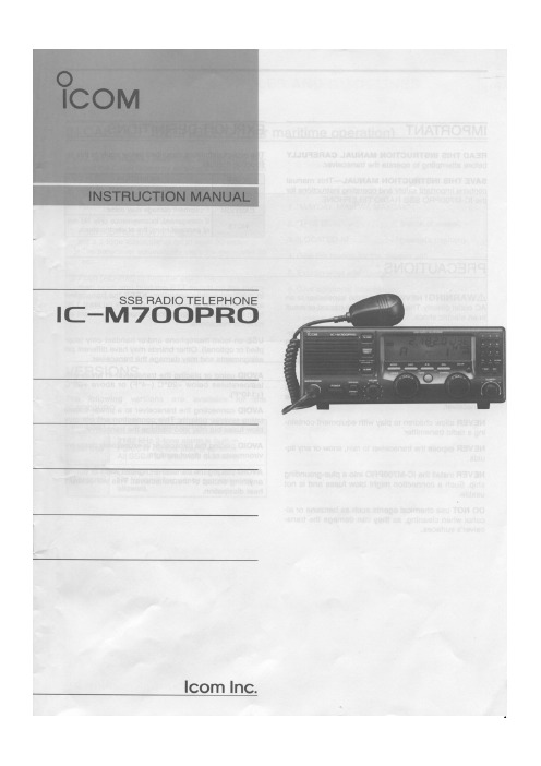
IC-M700使用手册 英文版
ZEISS IOLMaster 700 安全更新(“PrintNightmare”)快速指南说明书
Quick Guide ZEISS IOLMaster 700 Sicherheitsupdate(…PrintNightmare“)ZEISS IOLMaster 700 Sicherheitsupdate (…PrintNightmare“)Bitte beachten Sie: Dieses Dokument ersetzt nicht das im Lieferumfang des Geräts enthaltene Benutzerhandbuch.Über das Update…PrintNightmare“ ist der Name einer Sicherheitslücke, die Geräte betrifft, die mit Betriebssystemen von Microsoft Windows laufen. Microsoft zufolge …besteht eine Sicherheitsanfälligkeit bezüglich Remotecodeausführung, wenn der Windows Druckspooler-Dienst unzulässigerweise Dateivorgänge mit bestimmten Berechtigungen durchführt. Ein Angreifer, der diese Sicherheitsanfälligkeit erfolgreich ausnutzt, könnte beliebigen Code mit SYSTEM-Rechten ausführen. Der Angreifer könnte dann Programme installieren, Daten anzeigen, ändern oder löschen oder neue Konten mit uneingeschränkten Benutzerrechten erstellen.“…PrintNightmare“ beeinträchtigt weder die Sicherheit noch die Funktionsweise von ZEISS IOLMaster 700. Dennoch bieten wir Ihnen ein Sicherheitsupdate (Patch) für Ihr Gerät an, um die Sicherheitslücke …PrintNightmare“ zu schließen. Erforderliches SpeichermediumUm das Update vor der Installation herunterzuladen, benötigen Sie einen leeren USB-Speicherstick mit mindestens 2 GB Speicherkapazität.Vorbereitung• L aden Sie die folgende Datei herunter und speichern Sie diese direkt in das Stammverzeichnis des USB-Sticks: - 000000-2485-398_Vs01_IOLMaster700UpdateOperatingSystem.uptWie Sie das Update auf ZEISS IOLMaster 700 installieren1. Schalten Sie IOLMaster AUS.2. Schalten Sie IOLMaster wieder AN.3. Rufen Sie den Anmeldebildschirm auf.4. Loggen Sie sich als …Administrator“ ein.5. S chließen Sie den USB-Stick, auf dem sich dasheruntergeladene Update befindet, an IOLMaster an.6. Rufen Sie die Einstellungen auf(über das Schraubenschlüssel-Symbol).7. Rufen Sie den Menüpunkt …Maintenance“ auf.8. Scrollen Sie herunter bis zum Abschnitt …Update“.9. Klicken Sie auf …Perform update“.10. S tarten Sie das Update, indem Sie im Pop-up-Fensterauf …Yes“ klicken.HINWEIS:D ieser Vorgang kann bis zueiner Minute dauern.11. Wählen Sie das Softwareupdate in der Liste aus.12. Klicken Sie auf …Run“.13. IOLMaster wird automatisch neu gestartet.14. N un installiert IOLMaster das Softwareupdate. DieserVorgang dauert zwischen 5 bis 30 Minuten. Bitte folgen Sie den Anweisungen auf dem Bildschirm. In Einzelfällen kann es notwendig sein, das Softwareupdate ein zweites Mal zu installieren. In einem solchen Fall wird IOLMaster Sie auch durch diesen zweiten Installationsprozess führen.15. S obald das Update vollständig ist, wird dasnebenstehende Dialogfenster geöffnet. Bitte lesenSie die Nachricht, um zu bestätigen, dass das Systemerfolgreich aktualisiert wurde.16. Klicken Sie …Close“, um den Aktualisierungsvorgangzu beenden.17. IOLMaster wird nun automatisch neu gestartet.18. Sie können den USB-Stick wieder entfernen.Entdecken Sie weitere Expertenvideos,Hilfsdokumente und allgemeine Fragen und Antworten bei ZEISS Product Insights.ZEISS Product Insights-WebsiteCarl Zeiss Meditec AGGöschwitzer Strasse 51-5207745 Jena, Deutschland/med**********************000000-1932-169-AddGA-DE-260821。
M700溶氧仪
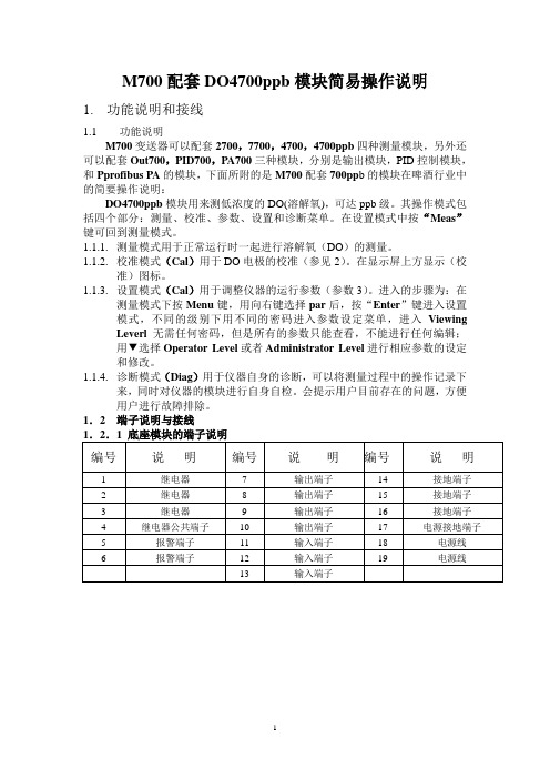
M700配套DO4700ppb模块简易操作说明1.功能说明和接线功能说明M700变送器可以配套2700,7700,4700,4700ppb四种测量模块,另外还可以配套Out700,PID700,PA700三种模块,分别是输出模块,PID控制模块,和Pprofibus PA的模块,下面所附的是M700配套700pp b的模块在啤酒行业中的简要操作说明:DO4700ppb模块用来测低浓度的DO(溶解氧),可达ppb级。
其操作模式包括四个部分:测量、校准、参数、设置和诊断菜单。
在设置模式中按“Meas”键可回到测量模式。
1.1.1.测量模式用于正常运行时一起进行溶解氧(DO)的测量。
1.1.2.校准模式(Cal)用于DO电极的校准(参见2)。
在显示屏上方显示(校准)图标。
1.1.3.设置模式(Cal)用于调整仪器的运行参数(参数3)。
进入的步骤为:在测量模式下按Menu键,用向右键选择par后,按“Enter”键进入设置模式,不同的级别下用不同的密码进入参数设定菜单,进入Viewing Leverl 无需任何密码,但是所有的参数只能查看,不能进行任何编辑;用▼选择Operator Level或者Administrator Level进行相应参数的设定和修改。
1.1.4.诊断模式(Diag)用于仪器自身的诊断,可以将测量过程中的操作记录下来,同时对仪器的模块进行自身自检。
会提示用户目前存在的问题,方便用户进行故障排除。
1.2 端子说明与接线1.2.2溶氧仪模块4700ppb接线端子号VP电缆82电缆2(阴极)透明线白线15(防护)灰线8(阳极)红线红线16(屏蔽)黄绿线黄绿线17(温度补偿)绿线黑线18(温度补偿)白线黑线注意:端子13和14跨接(短路)2.校准模式(单点校准)2.1 进入校准模式:进入校准模式的步骤为:在测量模式下按“Menu”键,用相邮件选择“Cal”,选择模块“Moudle O2 4700ppb”,按“Enter”确认,进入校准菜单。
M70M700 PLC编程Ver
M70/M700 PLC编程三菱电机技术部2008年8月•打印输出通用打印机•梯形图制作•PLC 信息制作•梯形图监控•离线开发个人计算机•梯形图打印输出•PLC 信息打印输出•CNC 装置•PLC 板内编辑画面•梯形图制作•梯形图监控•ROM 写入本图摘自IB-1500279-D M700 PLC编程说明书I-2页2.1 PLC处理程序的级别和动作2.2 PLC处理程序概要(2种编程方式)的编程管理方法,已经在原先单程序方式之外,又添加了一种多程序方式。
2.4 PLC处理程序的处理和执行方式PLC 定时计数01特殊功能使用的继电器和寄存器。
固定定时器和可变定时器点数设定方法:C (范围:C0~C255)。
该模式下仅可以使用与以往兼容的PLC指令规格。
如使用扩展的PLC指令,输入、编辑和运行时将发生错误。
包括“兼容PLC使用控制设备的CRT设定显示装置,可以实现与机床操作开关相同的功能。
开关的点数为32点,可通过PLC 开关画面以及用户PLC 打开或关闭。
此外,开关的名称可任意设定。
对应接口分为输入X接口(X680~X69F)、输出Y接口(Y680~R2521,R2523内容最大值负载表显示处理有效(a)整个条形图长度(最大值30(十进制))(b)条形图灰色部分长度(a)和(b)的差值为红色部分的长度R2520数值以五位数显示(二进制0到32767)R2522数值以五位数显示(二进制0到32767)条形图按R2521数值显示条形图按R2523数值显示红色部分灰色部分「读出窗口」或者「写入窗口」,读出/写入CNC的运行状态、轴信息、参数、刀读出主轴Z轴负载4.1 PLC程序、参数、装置注释文件命名方法4.2 信息数据文件命名方法(一)方式1)通过位选择参数#6453 的位0-2,共3 位进行指定的方式(PLC单独的语言4.2 信息数据文件命名方法(二)4.3 信息数据文件命名方法(三)5、GX Developer5.1 GX Developer创建M7PLC程序的流程选择菜单[Project]-[New Project],显示[New Project]设置界面,选择PLC系列及类型CPU类型必须选择Q4A,否则传输程序时会报错。
简要操作说明_M700_Cond Ind 7700模块(0510)
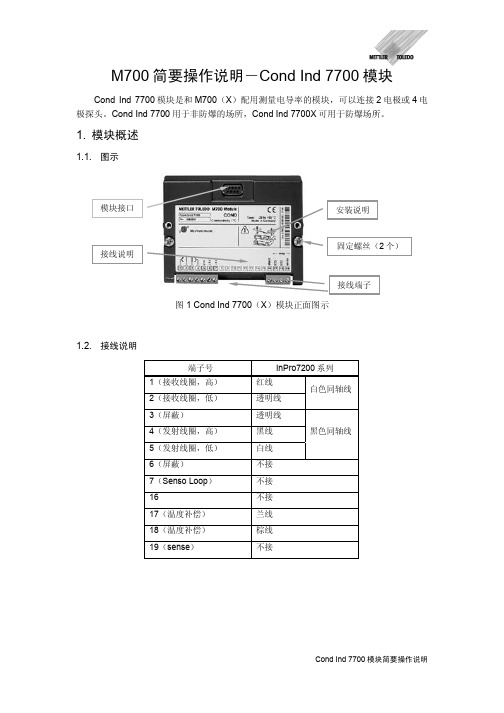
M700简要操作说明-Cond Ind 7700模块Cond Ind 7700模块是和M700(X )配用测量电导率的模块,可以连接2电极或4电极探头。
Cond Ind 7700用于非防爆的场所,Cond Ind 7700X 可用于防爆场所。
1. 模块概述1.1. 图示图1 Cond Ind 7700(X )模块正面图示1.2. 接线说明端子号 InPro7200系列1(接收线圈,高) 红线2(接收线圈,低)透明线白色同轴线3(屏蔽) 透明线 4(发射线圈,高) 黑线 5(发射线圈,低) 白线 黑色同轴线6(屏蔽) 不接 7(Senso Loop ) 不接 16不接 17(温度补偿) 兰线 18(温度补偿) 棕线 19(sense )不接2. 校准(cal)2.1. 校准前的准备2.1.1. 进入校准菜单在测量模式时按“Menu”进入菜单模式,用ef箭头键选定校准图标“cal”,按“Enter”确定。
用箭头键输入密码1147,按“Enter”键确定系统进入校准子菜单。
选择Cond Ind 7700模块(图2),该模块的校准方式包括(参见图3):¾Automatic with standard cal solution:用标准溶液自动校准探头;¾Manual entry of cal solution:手动输入校准溶液的值;¾ Product calibration:用已知电导率值的样品校准探头;¾ Data entry:输入探头的电极常数;¾ Zero correction:零点修正。
2.2. 用标准溶液自动校准的步骤2.2.1. 选择校准方式“Automatic with standardcal solution”,按“Enter”确认,出现如图4的显示。
确认校准溶液是否与设定的相同(标准溶液的选择见 4.3.2),如校准温度补偿为手动(参见 4.3.1),需要输入标准溶液的温度。
梅特勒-M700 感应电导率模块、OUT模块调试
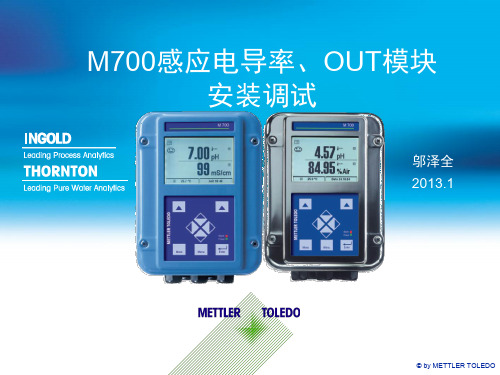
模块顺序
插在里面的模块,称为一号模块,用 表示
插在外面的模块,称为二号模块,用
每台M700仪表只能接两块测量模块。
表示
© by METTLER TOLEDO
进入设置
设置菜单的进入路径如下:按下“Menu”键
,选择“par”图标,按回车键,按往下键选 择“Administrator level”,输入密码1989( 用四个箭头键输入),选择相应的前面板、后 面板或模块。后面进入参数设定均按此路径, 不再重复。
3
© by METTLER TOLEDO
接线
芯线 黄 与4短接 紫 芯线 黄绿相间
绿
白
灰
红
黑
© by METTLER TOLEDO
M700的面板
在测量界面下 按此按钮,屏 幕左下角将按 顺序显示出各 种测量参数
无论在任何界 面下,一直按 此按钮可以返 回测量界面
© by METTLER TOLEDO
© by METTLER TOLEDO
OUT模块
进入设置菜单,选择“Module Out
700”模块
这里可以配置第三、第四路模拟输出和
及另外四路继电器输出,配置方法与前 文讲述的相同。
© by METTLER TOLEDO
Thank you!
© by METTLER TOLEDO
注意:本仪表没有中文语言,请勿进入
“Languages”语言菜单进行设置。
© by METTLER TOLEDO
背板设置-4~20毫安输出
选择“Module BASE”,按回车进入 选择"Output current 1或2”,按回车进入 Variable——选择哪个模块的哪个测量值进行
IC-7000用户手册说明书
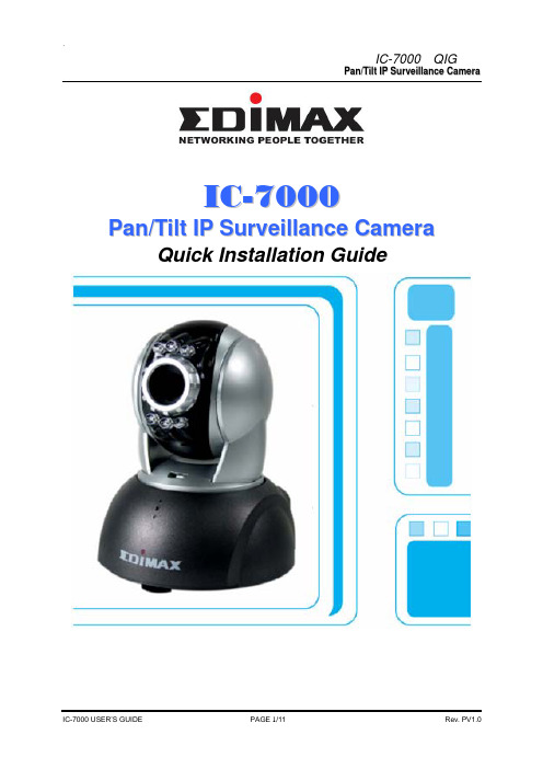
I C-7000P a n/T i l t I P S u r v e i l l a n c e C a m e r a Quick Installation Guideby Edimax Technology Co, LTD. all rights reserved. No part of thisAnchorFrameScrew (P head M3.5X25)When the installation is completed, you will get ” CAM_EZ Search “ as follows CAM_EZ Search is a camera search utility comes with this product. It can search all IP CAMs connected to LAN by sending broadcasting packets. After IP CAM responds the inquery packet, the utility will display a list of all IP CAM found on LAN. And it allows you to modify the settings of specified IP CAM, such as IP address or the name of IP CAM.figure 1B. Make sure the IP addresses of PC and IP CAM are on the same networkOpen and execute CAM_EZ Search (as shown in Figure 2). The system will scan the IP-CAM that you just installed automatically. Then, you will find255IC-7000 in the column of Camera Lists. Click 255IC-7000 with left mouse button. You can see the default settings of IP-CAM.Figure 2 2.3 N ETWORK S ETUPOpen and execute CAM_EZ Search (as shown in Figure 3). The system will scan the IP-CAM that you just installed automatically. Then, you will find255IC-7000 in the column of Camera Lists. Click 255IC-7000 with leftFigure 3z Fill static IP Address as shown below. (If you do not know your IP address, please contact your ISPshown below)`IC-7000 QIGP a n/T i l t I P S u r v e i l l a n c e C a m e r aPV1.0IC-7000 USER’S GUIDE PAGE 11/11 Rev.。
Icom IC-7000常见问题解答说明书
Icom IC-7000 Frequently Asked Questions (FAQ)This guide was created to answer the most commonly asked questions about the Icom IC-7000. The goal is two-fold:1) Condense the discussions found in the Yahoo group to the raw information providing a definitivesource for the FAQ reader2) Remove these recurring questions from the group to improve the “signal to noise ratio” Instructions for updating, correcting and adding information are located at the end of this FAQ.IC-7000 Unique Features• The IC-7000 was the smallest multimode radio available at its introduction (and the time of this writing)• It was the first truly mobile radio to feature IF-DSP (customizable filters – nothing to buy)• Filter width adjustable by mode with “sharp” and “soft” shape factors• Dual ADI Blackfin DSP Processors - feature set similar to the IC-7800, IC-756 Pro III• ACG loop performance controlled by DSP• Auto notch plus dual manual notch filters for up to 70 dB of attenuation• Noise blanker features adjustable pulse width and depth of cut• Internal RTTY decode and dual peak RTTY filter• High stability crystal oscillator is standard• Voice synthesizer standard• VFO knob includes a working “spinner”• The VFO knob tension is adjustable from free to tight and detented – great for mobile operation!• Microphone and external speaker jacks on both the head and body• Color composite video output available at all times to support a larger monitor• Multifunction display shows complete receiver status, S-meter/power output, ALC, compression, SWR and final temperature on a single screen• Semi-real-time spectral display 25-500kHz wide with peak hold and SWR sweep meter• VHF NTSC TV reception with internal modification• Many functions, including band stack registers, direct frequency entry, mode, filters and speech synthesizer available directly via the microphone (no menu navigation required) • Two programmable function keys on microphone for most used functions• CW/Voice memory keyer with 4 memories each and internal recorder feature• CW/voice keyer directly accessible with simple box described in manual• Thermostatically controlled fan• Less receive standby current draw than the IC-706MKIIG• Remotely mountable head• 6-pin data jack and 13-pin accessory jack• Customizable opening messageUser Measured SpecificationsPower outputThe IC-7000 maximum output power drops as voltage drops. This behavior is consistent with other radios as shown by the Yaesu FT-450 results below.The band tested below was not specified.13.84 2.0 17 9313.49 2.0 17 9213.01 2.0 17.5 9212.50 2.0 17.5 9012.02 2.0 16.0 8011.50 2.0 14.5 7011.01 2.0 14.0 6010.50 2.0 12.5 5010.00 2.0 11.5 409.50 2.0 XMIT FAILEDVoltage measured at power supply. Cables supplied by Icom. Power out as indicated in CW mode on attached tuner into a dummy load. At full voltage I had a full 100w PEP on SSB.<Marc W0KYZ>By comparison, these are the measurements that I obtained from a new Yaesu FT-450AT late last year: 13.8V - 100W12.5V - 100W12.0V - 75W11.5V - 68W<VR2AX> I looked up the % charge chart for my Trojan Deep Cycle battery:100% 12.70V80% 12.46V75% 12.40V50% 12.20V45% 12.16V25% 12.00V10% 11.94V5% 11.92V Discharged @ 11.90V<Jack_son>Receive standby currentIcom specs say 1.3A on receive squelched and 1.6A full volume.I checked mine. I got 1.36A two minutes after power up with default settings on 2m FM. Full volume (painful) was1.52A. I found I could save about 40mA by reducing "LCD Bright" to minimum (and still read the display) and another 40mA by turning off the switch backlighting. The readings were a little tough to validate because the fan is variable speed and can affect the readings by more than 100mA.These numbers seem consistent with the published Icom specs. It's not exactly milliamps but it's still 500mA less than the IC-706MKIIG specs. <Scott N7SS>How do I…?How do I hook a monitor to my IC-7000?The IC-7000 uses a 1/8” mono mini jack to provide composite video out. Any monitor, TV or VCR that supports composite video input (yellow RCA jack) can be used as a display. Although the 1/8” mini jack is small, it’s not a standard video connector. Radio Shack offers a 6 foot cable (Catalog #: 42-2444) for only a few dollars that has a 1/8” mini plug to RCA plug and will connect the IC-7000 directly to a standard composite monitor/TV.It is also possible to use an adapter to convert the 1/8” mini jack to an RCA to allow the use of a standard RCA cable. Rigid adapters should be used with caution because the jack can be pulled off the main board if too much torque is applied.“To use with a standard computer monitor, it is necessary to convert the composite video to RGB video with a device like the KWorld TV Box 1680ex.I use this one and it works ok but the above is better: /mpd/tvbox9.html<Steve Ellington, N4LQ>How do I use a Bluetooth headset with my IC-7000?“Works great. See link below from K7SFN. /projects/bluetooth.html”<Dave, KI4KQ>How do I connect more than one CI-V device to my IC-7000?The Icom CI-V interface is a serial bus design. This allows more than one device to be connected to the radio CI-V interface (amplifier, antenna switch, SteppIR antenna, additional radios, etc.). “To connect these devices get a flexible adapter like the Radio Shack 42-2437 or even a three-way adapter like the Radio Shack 42-2458”. <Doug Faunt, N6TQS>How do I get better transmitted audio?The IC-7000 was designed as a mobile radio and the microphone was intended to be used in high noise environments. Although the Heil microphones and W2IMY equalizers provide excellent audio, many people want to maintain the functionality of the stock microphone and get better audio without the expense of these options. AB5N has created a modification for the stock microphone at/ that creates a “hotter” microphone and higher quality audio. There is also a microphone modification posted at http://www.mods.dk/.The IC-7000 has two microphone jacks but the Icom manual specifically states that only one microphone should be used at a time. This is likely because both microphones would be hot at the same time. Some have suggested a mute switch (disabling the mike element) in the stock microphone. This would allow the stock microphone to be used as a “remote control” in one mike jack with a headset in the second mike jack.How do I use my IC-7000 on 60m?Page 40 of the IC-7000 manual provides information on 60m operation and is quoted below.To assist you in operating the 5 MHz band correctly within the rules specified by the FCC, transmission is impossible on any 5 MHz band frequency other than the 5 frequencies indicated in the table below.IC-7000 Display Frequency* FCC Channel Center Frequency*5.33050 MHz 5.33200 MHz5.34650 MHz 5.34800 MHz5.36650 MHz 5.36800 MHz5.37150 MHz 5.37300 MHz5.40350 MHz 5.40500 MHzNOTE: We recommend that you store these frequencies, mode and filter settings into the memory channel for easy recall.*The channel center frequencies that are specified by the FCC, show the center frequency of their passband. However, the IC-7000 displays carrier point frequency, so set 1.5 kHz below from FCC channel center frequency.How do I get full power output when transmitting?The IC-7000 was designed to deliver full power output at 13.8 volts. This is the voltage provided by most power supplies and the alternator output of a vehicle. The voltage table at the beginning of this FAQ shows output as voltage drops. When using the radio from a battery it is necessary to use the largest possible power cabling and a battery voltage booster to maintain the 13.8 volts required for maximum output.I use my IC7000 on CW almost exclusively, and I operate ONLY mobile. I use the N8XJK booster / with no problems at all. For a while I used it with the RF sensing, but no longer do so... not because of any performance problems, but because when the engine is running I don't need the booster, and when in receive I don't hear any noise problems from the booster, so I decided to so away with the additional wiring needed to use the RF Sensing. <Dave- K9FN>“I will ad that the MFJ-4416 voltage booster has helped greatly when the vehicle isn't running. This radio and many other mobiles do not Tx full output power on less than 13+ volts. So either get a battery voltage booster or keep the vehicle running.” <AE5MH>How do I use my radio in VOX mode?“Two things two check. You are in a voice mode and you have turned VOX on. I just tried it and it works with the stock 151 microphone. Be sure the word VOX shows up on your display.” <Steve EllingtonN4LQ>“Turn the VOX Gain up reasonably high, and turn the Anti-VOX as low as you can with out the speaker triggering the VOX. My 7000 works great with stock microphone in VOX mode.” <Dave - KI4KQ>How do I access the CW/Voice memory keyer?The CW and voice keyer options are accessible through the menu. When using the keyers via menu, it is not possible to access other features or the popular multimeter screen. There is a simple resistor network with switches shown in the manual to allow immediate access to the CW/voice memory keyer.“I made the device in the photo for solve this problem using the circuit at the 135 Page. I use my 7k for contesting and expeditions so the voice message function is a powerful help but use it via the menus is complex. /ea1nt/7kbox.htm <Luis EA1NT>How do I use a Turbo Tuner and screwdriver antenna with an IC-7000On the Turbo Tuner Web site, N2VZ is shipping Turbo Tuners setup for the 7000 AND the software update for Turbo Tuners that were programmed for 706, to make it a 7000 tuner. He will email you the update to flash your 706 Turbo Tuner thru the RS232 port on the Turbo Tuner./<Kent KQ4KK>How do I enter DTMF tones for Echolink/IRLP or repeater control?The stock IC-7000 microphone has many functions but like the IC-706 family, it can’t generate DTMF tones. There are two solutions offered by Icom. The first option is the same DTMF microphone used by the IC-706, the HM-154T.There are also 4 DTMF memories of up to 24 digits described on page 67-68 of the IC-7000 manual. This allows recording command/control sequences in these memories. Set Menu Option 38 specifies which DTMF option appears when F-2 is pressed in the menu.Can I use my IC-706 accessories with my IC-7000?Most accessories from Icom and third parties will work directly with the IC-7000. There are a few exceptions. The Icom remote kit is different for the IC-7000. The body and head bracket are the same but the remote cable has 10 pins, rather than only 8 pins. The microphones are largely compatible but the IC-7000 does not have an audio output line in the microphone cable. This could effect some TNC cables and older Heil headsets. The later Heil headsets have a separate speaker plug. There have also been some compatibility issues with third-party tuners (LDG and Turbo Tuner) although ROM upgrades are generally available to address these issues.Where do I find…?DC Power connector“New HF radios from Japan, introduced in the past 5 years operating on 12V DC, like the ICOM IC-7000, Kenwood TS-480, Yaesu FT-450, Yaesu FT-2000, and the new ICOM entry level radio all use the same connector, wired the same way.” <John Bee N1GNV – Quicksilver Radio>Quicksilver Radio - /DCpower.htmTower Electronics - /Powerwerx - /Wimo - http://wimo.de/cgi-bin/verteiler.pl?url=netzgeraete-zubehoer_d.htmlMonitorThere are too many monitor options available from too many sources to list here. The IC-7000 provides composite video out. This can be run into most TV sets and VCRs with the appropriate cable (1/8” monaural mini plug to RCA plug).Small monitors can often be found on eBay and any place that sells car audio/video. In-dash DVD players and many navigation systems include a composite video input. There has even been some discussion that a Toyota Prius instrument panel has an input that could be used for an IC-7000.Icom uses a 7” Xenarc 700YV monitor in the display they use at hamfairs. This monitor is more than what is necessary for most users. The rated LCD brightness of 500 cd/m² and contrast ratio of 400:1 crates a nice image. These are the two most important numbers when determining the quality of an LCD display. Often these numbers are not available and the price is the only indication of the relative monitor quality.CI-V computer interfaces for serial and USBIcom sells the CT-17 interface, which offers 4 CI-V ports and a single DB-9 serial port. There are a number of less expensive options available on the market in both serial and USB. These are commonly found on eBay. Radio Shack also has some scanner programming cables that will work.“I purchased the Radio Shack 20-047 USB Programming Cable & Driver Software today.(the number and description is right off their label)I followed their directions and connected the USB plug after installing the driver. It connects at 19,200 bps and has not given one sign of improper connection...This is faster and easier than the CT-17.I used a 20 foot stereo extension to get to the ICOM and used the stereo to mono adapter supplied with the interface to plug in at the radio end of the connection.18 hours later, I am sure this is the best way to go.” <im2old2run>Interfaces are also available from:West Mountain Radio - /RIGtalk.htmMFJ /Product.php?productid=MFJ-5383IControl softwareThe IC-7000 is similar to the other Icom HF radios and can use much of the same software written for the IC-706 family (although the radio address may need to be changed). More software is offering native IC-7000 support. One of the first and best is Ham Radio Deluxe (HRD) and is available for download at no cost from /.Memory programming softwareThere are a number of packages specifically designed to program the memory channels in the IC-7000. Rumtrol7k http://www.dl2rum.de/rumsoft/RUMtrol7K.htmlIC7000BKT /ic7000bkt_en.htmCI-V Cat.program/Memory Manager http://www.tellina.nl/software/Radio IssuesThe IC-7000 runs hot even on receiveThere are reports of the IC-7000 running hot despite most of the radio body being cooler than the IC-706. There are three points in particular that can run warm; the display because of the backlight, the area behind the speaker where the DSP ICs are heat sinked and the actual heat sink on the back of the radio. Here is a chart showing relative temperatures of various devices with color displays. The temperatures below were taken with an infrared thermometer after a 24 hour warm-up period at 71 degrees F with no transmit.Icom IC-7000 91°F 33°CIcom IC-2800 107°F 41°CSharp 15” TV/Monitor 85°F 29°CG2G 5” TFT Portable Monitor 106°F 41°CInitial 7” Portable DVD Player 85°F 29°CThe display runs about 91°F. The heatsink on the rear runs 99-103°F (in receive). The cooler areas on the back are 92-96°F. The temperature on the top ranges from 95-109°F. The area directly behind the speaker is the hottest at 109°F. This is directly over the silver box containing the DSP chips.The thermometer on the multimeter display shows the rear heatsink temperature. The final output transistors use this heatsink.Many users have installed fans over or behind the radio to increase the airflow over the chassis. Care must be taken with fans in dusty environments. There is also a fan modification published onhttp://www.mods.dk.Strange behavior on transmit (shutting down, resetting, changing frequency, etc.) This is most commonly a grounding/RFI issue. Make sure the radio and antenna are properly grounded. If the separation cable is being used, attempt to route it away from RF sources and be sure to use the screw to attach it to the radio.Audio feedback during transmitCheck to make sure you don't have the "monitor" turned on. Usually, you just use the monitor when transmitting digital modes.• Push SET button (AF gain control knob) upper left hand corner of radio.• Go to "Set Mode" > OTH > Monitor. Set to OFF<Brian, KC4UKR>High frequency (8kHz) tone in audioVery early models of the radio had a noticeable tone at 8kHz. This was not audible through the internal speaker because the internal speaker is “communications grade”, meaning it has a frequency response limited to voice frequencies. It was also not audible when using Heil, David Clark and othercommunications headphones or speakers. It was most obvious when using inexpensive “Walkman” style hifi headphones which are excellent at reproducing non-voice frequencies.Icom addressed this within a few months after production began with some capacitor and grounding changes. This modification should be available at no charge for units in warranty.Low level hiss in audioMany radios have a small amount of hiss (white noise) when the volume is set to the minimum value. This hiss remains at a constant level as the volume is increased and is quickly overwhelmed by signal audio. The hiss is apparently internally generated. There is no known solution but some users insert attenuators in the audio line. Since the hiss is a fixed level, it will reduce the hiss level while allowing the signal level to be increased with additional AF gain.This audio hiss is very low through the internal speaker because it is “communications grade”, meaning it has a frequency response limited to voice frequencies. Any external speaker or headphones should also be designed for communications work, rather than hi-fi, so as to minimize this issue.S-meter reads lowThe IC-7000 S-meter is very accurate but as a mobile unit is calibrated to read accurately with the preamp enabled.Changing the transmit audio bandwidth results in poor transmit audioThe Icom IC-7000 supports changing the transmit audio bandwidth. There are three predefined settings which can be modified. Because it appears the transmit equalization feature was cut, there is no way to rebalance the audio as the bandwidth is narrowed. This makes the audio quality very poor at narrow bandwidths. If DX-quality narrow audio is desired, the best solution is a good DX microphone or an external equalizer like those from W2IHY.。
m70m700plc基本操作使用
三菱电机自动化(上海)有限公司营业技术GMITSUBISHI CNC PLC 基本操作(M70/M700)_VerA0PLC基本操作PLC基本操作-M70/M700三菱电机自动化(上海)有限公司营业技术GMITSUBISHI CNC PLC 基本操作(M70/M700)_VerA0PLC基本操作目录1.M7的PLC 接口的系统构成2.M7的PLC 开发环境3.GX Develoer 创建新的M7PLC 程序4.M7的离线传输操作5.M6到M7的PLC 格式转换6.M7的联机操作三菱电机自动化(上海)有限公司营业技术GMITSUBISHI CNC PLC 基本操作(M70/M700)_VerA0PLC基本操作M7的PLC接口的系统构成M7系列提供了更多的扩展I/O单元接口.M7的PLC接口构成三菱电机自动化(上海)有限公司营业技术GMITSUBISHI CNC PLC 基本操作(M70/M700)_VerA0PLC基本操作M7PLC的开发环境M7的PLC主要有离线开发和联机操作两种方式.M7的开发环境三菱电机自动化(上海)有限公司营业技术GMITSUBISHI CNC PLC 基本操作(M70/M700)_VerA0PLC基本操作M7的离线开发M7的离线开发是指通过PC机开发PLC程序,再传输到NC的开发过程.实现步骤:•使用GX Developer软件创建PLC程序•PLC程序传输到NC以太网方式RS232C方式IC卡方式M7的离线开发三菱电机自动化(上海)有限公司营业技术GMITSUBISHI CNC PLC 基本操作(M70/M700)_VerA0PLC基本操作GX Developer创建新的M7PLC程序M7的离线开发三菱电机自动化(上海)有限公司营业技术GMITSUBISHI CNC PLC 基本操作(M70/M700)_VerA0PLC基本操作GX Developer创建新的M7PLC程序一.新建M7PLC项目二.进行GX Developer的通信设定三.装置点数的修改四.允许将M7 LADDER写入NC ROM的设定五.编写M7PLC信息文件六.将编写好的M7PLC程序写入到NC缓存七.将M7PLC程序写入到NC ROM八.M7PLC信息文件的命名方式九.M7PLC信息文件编写的注意事项M7的离线开发三菱电机自动化(上海)有限公司营业技术GMITSUBISHI CNC PLC 基本操作(M70/M700)_VerA0PLC基本操作新建M7PLC程序项目M7的离线开发选择功能表下[Project]-[New Project],显示[New Project]设置界面,设定PC 机类型点击OK 确定打开新建程序编辑画面.选择PLC序列及类型CPU类型必须选择Q4A,否则传输程序时会报错.选择PLC程序类型为梯形图类型三菱电机自动化(上海)有限公司营业技术GMITSUBISHI CNC PLC 基本操作(M70/M700)_VerA0PLC基本操作选择功能表下[Online]-[Transfer-setup],显示Connection Setup 界面.M7的离线开发进行GX Developer的通信设定界面的设置根据选择通信方式的不同而进行不同的设置.三菱电机自动化(上海)有限公司营业技术GMITSUBISHI CNC PLC 基本操作(M70/M700)_VerA0PLC基本操作双击画面左侧树状显示的[Parameter]下的[PLC parameter],出现[QnA Parameter]画面.选择[Device]页,将[Inside relay][M]的[Dev.point]改为10K,[Retentive timer][ST]的[Dev.point]改为64.M7的离线开发装置点数的修改三菱电机自动化(上海)有限公司营业技术GMITSUBISHI CNC PLC 基本操作(M70/M700)_VerA0PLC基本操作双击画面左侧树状显示的[Parameter]下的[PLC parameter],出现[QnA Parameter]画面.选择[PLC system]页,选中[Remoter reset]栏内的[Allow],按下[END]键.若不选择,写入操作将无法进行.M7的离线开发允许将M7 ladder写入NC ROM内的设定三菱电机自动化(上海)有限公司营业技术GMITSUBISHI CNC PLC 基本操作(M70/M700)_VerA0PLC基本操作选择[Online]-[Remote operation]菜单,[Operation]栏的下拉菜单内选择[STOP],按下[Execute]键后,PLC停止.[Operation]栏的下拉菜单内选择[Pause],按下[Execute]键后,PLC写入ROM中.M7的离线开发将新建M7PLC程序写入NC ROM三菱电机自动化(上海)有限公司营业技术GMITSUBISHI CNC PLC 基本操作(M70/M700)_VerA0PLC基本操作PLC 中除了基本的梯形图外,还包含了相关的报警信息﹑操作员信息﹑PLC 开关信息以及注释信息等.这些信息也可通过GX Developer 直接在线编写.各种信息的编写有其固定的格式,即使信息字符串为空白时,也要记叙[,]和[CR].M7的离线开发编写PLC的信息数据(必须在WRITE MODE下)三菱电机自动化(上海)有限公司营业技术GMITSUBISHI CNC PLC 基本操作(M70/M700)_VerA0PLC基本操作依次打开GX Developer的[Project][Edit Data][New]菜单设定[Data name]和[Title],点击[OK]确认.M7的离线开发PLC信息文件的数据名PLC信息文件的标题PLC数据类型新建PLC的信息文件三菱电机自动化(上海)有限公司营业技术GMITSUBISHI CNC PLC 基本操作(M70/M700)_VerA0PLC基本操作再依次打开[View][Statement],即可进行编辑操作.双击需要编辑的行间,在弹出的对话框中编辑,点击[OK]确定.编辑完成后使用PLC写入操作方法,传输到NC内.M7的离线开发新建PLC的信息文件三菱电机自动化(上海)有限公司营业技术GMITSUBISHI CNC PLC 基本操作(M70/M700)_VerA0PLC基本操作选择[Online]的[Write to PLC]菜单,显示[Write to PLC]界面.选择[File selection]页面,将树状显示的编辑好的各个PLC 程序文件分别选中,按下[Execute]键,将PLC 写入NC.M7的离线开发PLC 程序信息文件PLC 程序LADDER 文件PLC 程序注释文件PLC 程序参数文件将新建M7PLC程序传入NC三菱电机自动化(上海)有限公司营业技术GMITSUBISHI CNC PLC 基本操作(M70/M700)_VerA0PLC基本操作M7的离线开发PLC信息文件的命名根据语言指定方式的不同而不同.PLC的信息文件的命名方式三菱电机自动化(上海)有限公司营业技术GMITSUBISHI CNC PLC 基本操作(M70/M700)_VerA0PLC基本操作PLC信息数据有其最大值,超过最大信息数量,写入时发生错误.超过最大信息长度,写入时超过部分不显示,可采用以下方法编写.M7的离线开发PLC的信息文件编写的注意事项三菱电机自动化(上海)有限公司营业技术GMITSUBISHI CNC PLC 基本操作(M70/M700)_VerA0PLC基本操作M7PLC程序的传输操作M7的离线开发三菱电机自动化(上海)有限公司营业技术G MITSUBISHI CNC PLC 基本操作(M70/M700)_VerA0PLC基本操作M7PLC程序的传输操作一.以太网方式传输M7PLC时的通信设定二.以太网方式离线操作M7PLC1.以太网方式读写M7PLC2.以太网方式在线监控M7PLC3.以太网方式在线修改M7PLC三.RS232C方式离线操作M7PLC1.将M7PLC项目保存到IC卡内2.将IC卡内的M7PLC程序传入NC3.将M7PLC文件保存到NC ROMM7的离线开发三菱电机自动化(上海)有限公司营业技术GMITSUBISHI CNC PLC 基本操作(M70/M700)_VerA0PLC基本操作选择功能表下[Online]-[Transfer-setup],显示Connection Setup 界面.M7的离线开发以太网方式传输时M7PLC的通信设定三菱电机自动化(上海)有限公司营业技术GMITSUBISHI CNC PLC 基本操作(M70/M700)_VerA0PLC基本操作在[Connection Setup]界面双击[PC-sideI/F]栏内的[Ethernet Module],出现[PC side I/f detailed setting of ethernet module]设定画面,输入NC的IP 地址.M7的离线开发选择AJ71Q5E71PLC单元型号(使用UDP协议通信)设置通讯NC的IP地址以太网方式传输时M7PLC的通信设定三菱电机自动化(上海)有限公司营业技术GMITSUBISHI CNC PLC 基本操作(M70/M700)_VerA0PLC基本操作以太网方式操作PLCM7的离线开发1.读取写入PLC选择[Online]的[Read from PLC]读取NC侧的PLC文件.选择[Online]的[Write to PLC] 将PLC文件写入NC侧.通过以太网进行PLC操作的优点是响应速度更快,传输更稳定.从NC 读取PLC 界面写入PLC 到NC 界面三菱电机自动化(上海)有限公司营业技术GMITSUBISHI CNC PLC 基本操作(M70/M700)_VerA0PLC基本操作2.在线监控PLC选择[Online]的[Monitor]的扩展菜单[Monitor mode],可以在线监控PLC,实时的观测到PLC信号状态的变化.M7的离线开发以太网方式操作PLC三菱电机自动化(上海)有限公司营业技术GMITSUBISHI CNC PLC 基本操作(M70/M700)_VerA0PLC基本操作3.在线直接修改PLC选择[Online]的[Monitor]的扩展菜单[Monitorwrite mode],可以在线修改PLC,实时的进行PLC的各种文件的修改.修改完成后需要[Convert].再通过[Remote operation]操作方式写入NC的ROM.M7的离线开发以太网方式操作PLC 正在修改区域三菱电机自动化(上海)有限公司营业技术GMITSUBISHI CNC PLC 基本操作(M70/M700)_VerA0PLC基本操作RS232C方式离线操作PLCRS232C方式的离线操作与M6机型一样.M7的离线开发三菱电机自动化(上海)有限公司营业技术GMITSUBISHI CNC PLC 基本操作(M70/M700)_VerA0PLC基本操作IC卡方式离线操作PLC1.将M7PLC项目保存到IC卡内通过GX Developer的[Project]菜单下的[Save as]将PLC程序保存到IC卡中.将IC卡插入NC,通过PLC联机操作将IC卡内的程序保存到NC的缓存中,最后写入NC的FROM里.M7的离线开发三菱电机自动化(上海)有限公司营业技术GMITSUBISHI CNC PLC 基本操作(M70/M700)_VerA0PLC基本操作M7的离线开发IC卡方式离线操作PLC2.将IC卡内的M7PLC程序传入NC按下NC[F0]界面进入联机操作界面,再依次按下[EXT.FILEOPERATION][EXT.→NC],会自动弹出IC卡的PLC程序一览界面.[Select]选中所需文件,[READ]读取PLC程序.三菱电机自动化(上海)有限公司营业技术GMITSUBISHI CNC PLC 基本操作(M70/M700)_VerA0PLC基本操作IC卡方式离线操作PLC3.将M7PLC文件保存到NC ROM.读取文件时NC会自动提示是否需要停止PLC,按提示操作.读取结束后需要将PLC程序写入NC的ROM中.在[F0]界面依次按下[NC FILE][ROM WRITE]键,进入ROM写入界面,按[YES]键执行.M7的离线开发三菱电机自动化(上海)有限公司营业技术GMITSUBISHI CNC PLC 基本操作(M70/M700)_VerA0PLC基本操作M6到M7的PLC格式转换M6到M7的PLC格式转换三菱电机自动化(上海)有限公司营业技术GMITSUBISHI CNC PLC 基本操作(M70/M700)_VerA0PLC基本操作M6到M7的PLC格式转换一.PLC4B格式的梯形图的转换流程二.获取M6的LKX形式梯形图三.以M5PLCWIN软件分解LK4文件四.以M5PLCWIN软件分解LK4文件,得到LAD和MSG文件五.以M5PLCWIN软件转换LAD文件成列表形式六.以CNVM6软件转换LAD列表文件成M7格式梯形图七.以CNVM6软件转换MSG文件成M7格式信息文件八.以CNVM6软件转换MSG文件成M7格式注释文件九.GX Developer中进行PLC参数设定,再导入上面三个文件十.在GX Developer中进行手工修改十一.M6(PLC4B格式)转换成M7后需注意的元件表M6到M7的PLC格式转换三菱电机自动化(上海)有限公司营业技术GMITSUBISHI CNC PLC 基本操作(M70/M700)_VerA0PLC基本操作由于M6等机型与M7的PLC 接口信号有所不同,要使用M6等机型的PLC,则必须要进行PLC 的转化.目前M6机型的PLC主要有PLC4B和GX两种格式.要进行格式的转化,需要使用到的软件有M5PLCWINCNVM6GX ConverterGX DeveloperM6到M7的PLC格式的转换M6到M7的PLC格式转换三菱电机自动化(上海)有限公司营业技术GMITSUBISHI CNC PLC 基本操作(M70/M700)_VerA0PLC基本操作PLC4B格式的梯形图的转换流程获取M6的LKX 形式梯形图以M5PLCWIN软件转换成LK4形式以M5PLCWIN软件分解LK4文件,得到LAD 和MSG 文件以M5PLCWIN 软件转换LAD 文件成列表形式以CNVM6软件转换LAD 列表文件成M7格式梯形图以CNVM6软件转换MSG 文件成M7格式信息文件以CNVM6软件转换MSG 文件成M7格式注释文件先进行PLC 参数设定,导入上面三个文件。
艾默生M700驱动器:选型手册

智能机器架构有何不同之处? • 标准网络硬件——没有限制的可集成性 • 轻松获得出色的性能——先进且易于使用的软件工具,经测试
可加快机器开发并能使机器发挥最佳性能 • 网络效率得到提高——非集中式网络智能消除了网络流量瓶颈 • 包容性网络——支持 PROFINET、EtherNet/IP 和 Modbus TCP/
支持以下 IEC 61131-3 编程语言:
• 结构化文本 (ST) • 功能块图 (FBD) • 结构化功能图 (SFC) • 梯形图 (LD) • 指令表 (IL) 还支持:
• 连续功能图 (CFC) 直观的智能感知功能有助于写入一致、可靠的程序,加速软件 开发。程序员可以使用充满活力的开放源代码社群获取功能 块。Control Techniques 还支持客户自己创建的功能块库,使用用 户定义的监视窗口在线监控程序变量,并支持在线程序更改。
Unidrive M 制造自动化驱动器系列
Unidrive M——专门针对客户需求定制的 制造自动化驱动器系列
Control Techniques依据以客户为导向的原则做了大量而广泛的市 场调研,并据此精心定制了 7 款 Unidrive M 的功能,以满足制造 自动化领域中特定的应用需求。Unidrive M700 具备板载实时以 太网,支持广泛的位置反馈和永磁伺服电机的高性能动态控制。 此外,对制造自动化领域的现有 Unidrive SP 用户而言,它可实现 全面兼容的升级。
Control Techniques 智能机器架构使用标准以太网将机器控制器部 之间的通讯,Unidrive M 使用 TCP/IP 和 UDP 等开放式协议,可提
件与其它设备(如 PC、I/O 和 HMI 等)连接在一起。以太网可为 供卓越的性能:
M700简要操作说明-基本单元和Cond Ind 7700模块 (2)
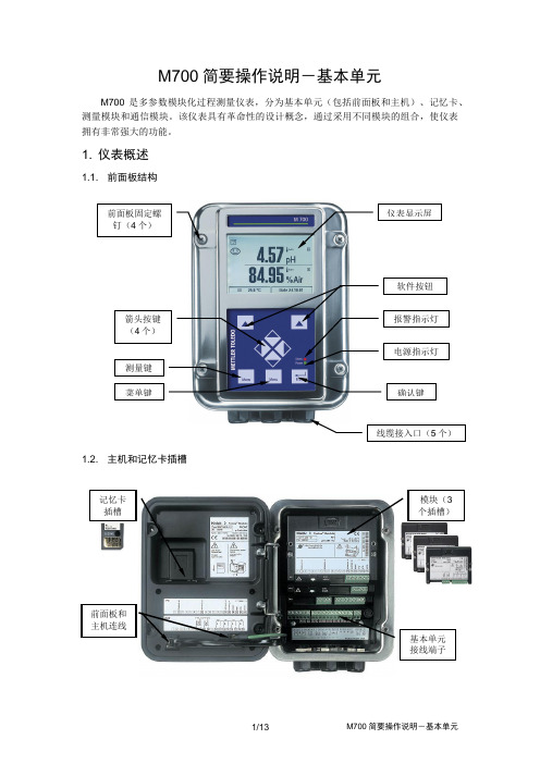
M700简要操作说明-基本单元M700是多参数模块化过程测量仪表,分为基本单元(包括前面板和主机)、记忆卡、测量模块和通信模块。
该仪表具有革命性的设计概念,通过采用不同模块的组合,使仪表拥有非常强大的功能。
1. 仪表概述1.1. 前面板结构1.2. 主机和记忆卡插槽基本单元接线端子记忆卡插槽前面板和主机连线模块(3个插槽)1.3. 可搭配的模块和测量参数1.4. 显示屏的说明2. 基本单元的接线2.1. 电源接线根据供电电源的不同,M700系列包括三种型号的仪表:➢ M700,普通型:24(-15%)至230(+15%)VAC/DC ;➢ M700X/VPW ,防爆型:100(-15%)至230(+15%)VAC (EEx em IIC ); ➢ M700X/24V ,防爆型:24VAC (-15%,+10%),24VDC (-15%,+20%)。
2.2. 主机接线2.2.1. M700接线端子说明:2.2.2. M700X/VPW 接线端子说明:2.2.3. M700X/24V 接线端子说明:3. 安装3.1. 仪器的安装M700(X )可以进行表盘式安装,也可采用合适的安装件进行墙式安装或立柱式安装。
详见仪器说明书。
3.2. 模块的安装模块安装步骤:1) 关闭电源;2) 旋松面板上的4个螺丝,打开面板盖; 3) 将模块插入插槽(D-SUB 插口)内; 4) 旋紧模块上的2个螺丝;5) 如果在模块上有ESD 屏蔽盖板,将其打开;6) 连接电缆线。
为避免干扰,电缆屏蔽必须被完全覆盖在ESD 屏蔽盖板内; 7) 关闭ESD 屏蔽盖板; 8) 关上仪器面板,并旋紧螺丝; 9) 接通电源;10) 设置参数(参见模块说明)。
3.3. 记忆卡的装入和取出某些模块的端子有ESD 屏蔽盖,装完电缆后须盖紧。
确保电缆线缩紧管被拧紧,以防止潮气侵入。
4. 菜单组结构4.1. 测量模式和菜单模式M700采用多级菜单结构,按前面板上的Menu键可进入菜单模式。
IC-M700TY中文说明书
当电台与天线调谐器相连接后,按下此开关,给天线调谐器送过去一个启动信号,此时天线调谐指示 灯亮。
等调谐完毕之后,天线调谐指示灯灭,收发信机返回接收状态。 10、 显示开关 DISPLAY SWITCH
在面板窗口左右两边各有一个,取下这两个螺钉,打开窗口,就可以使用数字键盘对存储器编程了。
二、后面板上的连接器
1、 天线插座 输出阻抗为 50Ω,应使用 PL-259 插头。当使用鞭状天线、长天线时,此插座应通过电缆连接至天线
自动调谐器。 2、 接地线
为了防止发生电击,避免其它无线电干扰,请将收发信机通过此端子接地。接地线尽可能使用比较宽 的铜带,接地线尽可能地短一些。 3、 外接扬声器插座
在 4Ω负载上,失真度为 10%时,输出功率不小于 5W。 8、 输出阻抗
2 ~ 8Ω 第二节、特征
1、 48 个存储频道 IC-M700 收发信机的频率范围覆盖了船岸通信、远洋电话、和船舶之间通信的所有频率,可以使用单
工、半双工方式工作,可以灵活地以 100Hz 的步进频率为收发频率单独编程。 本机具有频率合成系统,可以通过前面板上的键盘进行编程并且存储下来。
设置所需要的工作方式 A3J、A3A、A3H。 IC-M700 在出厂时,已经存入常用的海洋通信频率。
三、频道的重新编程
当需要使用其它频率时,应对频道重新编程。 (1)用波道组开关任选 A、B、C、D 中的任何一个波道,再用频道开关任意选择 1~16 个频道中的一个。 如果原频道没有存储频率,则面板上的频率显示器上只有 MHz 和 kHz 位上由小数点在闪亮。 (2)拆掉频率显示器窗口两边的螺丝,卸下窗盖,露出键盘。 (3)首先预置接收频率,看准键盘上所标注的 0~9 的数字键。把所需要频率的 6 位数字(最低位是百 Hz 位),从最高位至最低位的顺序依次按压数字键,此时显示屏幕上显示出的数字就是所设置的频率值。 如果输入出现了错误,可按一下复位键 CE,则输入的频率被删除而恢复到初始状态,然后重新输入。
ICOM IC-M700PRO 使用说明手册
注意
△! 危險!禁止把收發兩用機直接接到交流電㆖。這樣會引起火焰或導致電擊。 △! 危險!禁止把收發兩用機安放在高於頭部的㆞方。此收發兩用機重約 8 公斤, 而且由於電波的沖擊和振動,將使其產生幾倍於其重量的力。必須把收發兩用 機安裝在平整的硬平面㆖。 禁止(直接)使用超過 16V 的直流電源,例如 24V 的直流電池。若(直接)接 到超過 16V 的直流電源㆖會燒壞儀器。 禁止兒童接觸此儀器,包括無線電發射機。 禁止淋㆖雨、雪,或浸㆖其他液體。 禁止 IC-M700PRO 接到正接㆞船㆖。這樣會導致保險絲燒壞而不能使用。 請勿用苯類,酒精等化學試劑擦拭儀器,這樣會損壞收發兩用機的表面。 用於船㆖時,請儘可能使收發兩用機和麥克風離磁性導向羅盤儀遠㆒些(至少 要 1 米以㆖),以防止出現不正確的顯示。 本品只能使用 ICOM 制的麥克風和手機(附帶或選)。 如使用其他廠商的產品,其針腳排列可能與本品不同,可能會導致儀器損壞。 避免在溫度低於-20 攝氏度獲高於+60 攝氏度的場合使用或放置。 請勿把收發兩用機的電源性接反(正負極和電源接反)。這樣連接不僅要燒壞保 險絲,而且還有可能燒毀收發兩用機。 避免雙重污染(弄髒)該儀器或把儀器曝曬於陽光之㆘。 請勿靠牆放置,請勿在收發兩用機㆖放置任何東西,這樣會影響其散熱。
該收發兩用機配有 150 個頻道,被分成 3 組,每組有 50 個頻道(最大為 50)。 而且,每組的頻道數還可以根據您的需 要加以限制。(詳見第 13、14 頁) &注:當用﹝2182kHz﹞開關來選擇 0 頻道或 2182kHz 頻道時,需先按㆘ ﹝2182kHz﹞按鈕,否則選擇不了頻道。 M如需要,可按﹝CH/FREQ﹞按鈕選擇 記憶模式頻道。 N先用旋轉按鈕﹝GROUP﹞選擇所需 頻道組,然後再旋轉旋鈕 ﹝CHANNEL﹞來選擇所需頻道。
M 700(X) 产品说明书
l–––––––––––––––
Power supply Overvoltage category Protection class Pollution degree Wire cross-section l–––––––––––––––––––––– Protection against electrical shock l–––––––––––––––––––––– EMC
TS-201.011-MTX03 240205
Safety information
Information on installation
Be sure to read and observe the following instructions! The device has been designed in accordance with the state of the art and complying with the applicable safety regulations. When operating the device, certain conditions may nevertheless lead to danger for the operator or damage to the device.
IC-M700PRO简单说明书
目录重要提示.....................................................ii 提示用语说明...............................................ii 注意...........................................................ii 遇险时的应急措施........................................iii 类型..........................................................iii 目录.........................................................iv 1 使用规则和指南.........................................1 . 2 盘面.....................................................2-4 ■前盘面...................................................2 ■显示窗口................................................4 3 选择频道和频率......................................5-7 ■记忆模式/VFO 模式..................................5 ■选择频道................................................5 ◊扫描功能.............................................6 ■选择频率................................................6 ■重新设定CPU.........................................7 4接收和发射............................................8-10 ■声音的基本接收和发射....... .......................8 ■发射诸功能..................... .......................8 ◊检查发射频率............... .......................8 ■接收诸功能....................................... .....9 ◊静噪功能.............................................9 ◊噪音抑制.............................................9 ◊关闭AGC 功能.....................................9 5 设定模式...................................................11-14 ■设定模式操作...............................................11 ■设定模式内容...............................................11 6 连接与安装................................................15-21 ■后面盘的连接..............................................15 ■标准配件....................................................15 ■连接器件性能参数........................................16 ■接地.........................................................18 ■电源.........................................................18 ■天线.........................................................19 ◊MN-100/MN-101L.......................................19 ◊AT-130.....................................................19 ◊非Icom 制调谐器........................................19 ■收发两用机的安装.......................................20 ◊安装位置.. (20)◊安装例.....................................................20 ◊收发两用机的尺寸......................................20 ■内部件的装配..............................................21 ◊外壳的打开...............................................21 ◊滤频器和报警总成的安装.............................21 ■保险丝的更换. (21)7 消除故障 (22)8 特性参数备选件............................................23 ■特性参数...................................................23 ■备选件......................................................23 ◊清晰度控制..........................................9 ■CW 操作...............................................10 ■FSK 操作. (10)■前盘面①麦克风接口(详见第16页) 可接附带的麦克见或备选手机。
M70 M700基本操作
画面操作
M70/M700基本操作说明
MITSUBISHI CNC M70/M700基本操作_VerA2
三菱电机自动化(上海)有限公司 CNC营业技术G
3
画面操作
M70/M700基本操作说明
显示项目 ⑴主画面名称
⑵菜单名称
⑶各个菜单机 能的简单说明 显示区域
详细内容说明
显示主画面的名称。 (例如:运行画面/设置画面/编辑画面 等)。 显示各个主画面的菜单(机能)明细一览 表。 (如:呼叫/再启动/描图/编辑等)
程序编辑机能
存放在NC 存储器的加工程序可以在此画面下进行编辑修改。
当按 下 菜单键以后,已经被呼叫的加工程序会被 显示在编辑画面上(如果在MDI模式下时,会显示MDI内的加工程序)。
如果在呼叫画面中没有呼叫任何加工程序时,画面内的编辑窗口区域将 不会被开启。
当加工程序在被编辑的时候,所编辑修改的资料会被直接写入程序区域。 从光标开始位置所有输入的资料,将会把原来的资料覆盖。
显示项目
详细说明
⑴NC名称显示
现在使用中的NC名称显示(显示名称由参数#1135设 定)。
⑵系统名称显示
当使用多系统控制加工时,显示当前系统名称(使用单 一控制系统时,名称将不显示出来)。
⑶电源重新开启要求警告 当相关重要参数被修改后,系统要求重新开启电源的信 息将显示在画面上。(PR:Power Return)。
再启动形式2
当加工因长时间休息或先执行其他程序等外在因素,而且 NC电源被关闭再启动时,加工可以从指定的单节号或是顺 序号处重新再开始加工。
MITSUBISHI CNC M70/M700基本操作_VerA2
三菱电机自动化(上海)有限公司 CNC营业技术G
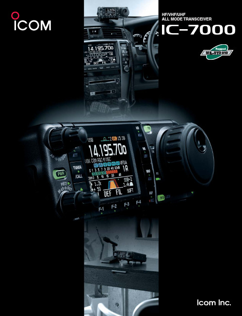
Yaesu IC-7000 高功率多频带无线电说明书
HF/VHF/UHFALL MODE TRANSCEIVERHF/VHF/UHF ALL MODE TRANSCEIVER35W output in 70cm bandHigh power MOS-FET amps supply 35W output power on 430/440MHz band as well as 100W on HF/50MHz bands and 50W on 144MHz. It pro-vides stable, high quality output with low IMD and low spurious emissions even during high duty cycle and extended operation.High stability crystal unitThe IC-7000 inco rpo rates a high-stability master o scillato r, pro viding 0.5ppm (–0°C to +50°C). A must for data mode operation.DDS (Direct digital synthesizer) circuitIcom’s original DDS (Direct digital synthesizer) circuit improves the C/N ratio, providing a clear, clean transmit signal in all bands.Compact, all in one packageThe IC-7000 sheds 20mm (0.79 in) of depth compared with the IC-706MKIIG. It’s compact body is easy for carrying outdoors or mobile operation.IF DSP — First in its classDigital IF fi lter, manual no tch fi lter, digital twin PBT and more. The lat-est digital features are incorporated in this compact radio from two DSP chips that deliver superior process-ing perfo rmance. Of co urse, tho se features work on all ham bands, from HF to the 70cm band.AGC loop performance controlled by DSPY ou will never experience AGC pumping from a signal filtered out by the DSP system. The digi-tal IF fi lter and manual notch fi lter are inside the AGC loop, so you will not encounter AGC block-ing. The AGC time constants are fl exibly adjust-able from slow, middle, fast (or AGC-off) for each operating mode.Digital IF fi ltersAll the fi lters you want at your fi ngertips! Y ou will never have to purchase “Optional” filters as the IC-7000 has adjustable digital filters. Y ou just dial in the width you wantand select whether you want a sharp or soft fi lter shape for SSB and CW modes. Then to pull-in the the weak ones, with a quickturn of the concentric twin PBT knobs, you can either narrow the IF passband, or shift the entire passband to eliminate the QRM.2-point MNF (Manual notch fi lter)Pull out the weak signals in crowded band condi-tions with Icom’s NEW two-point MNF (manualnotch fi lter). Apply 70 dB of rejection to two sig-nals at once! Notch width is adjustable – wide, medium, and narrow – and an auto-tuning notch fi lter is available, too.Digital noise reductionNoise reduction reduces background noise and improves signal-to-noise ratio. The noise reduction level is adjustable in 16 steps. It improves the readability of voice and data signals.Digital noise blankerThe noise blanker reduces pulse-type noise such as engine ignition and sparking. The NB level and width (blanking duration) are adjustable in 100 steps.AGC time constant setting Manual notch fi lterIF fi lter settingMOS FET P A unitsIcom original DDS circuitThe technical properties and advantages of IF DSP found in our leading base station models now offers its superior advantages on mobile HF, 50MHz 144MHz and 430/440 MHz bands.2.5 inch color TFT displayThe 2.5 inch color TFT display presents numbers and indicators in bright, concentrated colors for easy recognition. Y ou can choose from 3 back-ground colors and 2 font styles to suit your preference, in addition to a large operating frequency readout. And more, the Video output jack on the rear panel allows you to view a magnifi ed display on an external monitor*.* 3.5(d) mm monaural cable is required for connection.SSB transmit bandwidth adjustableThe SSB transmit bandwidth is selectable from 100, 200, 300, 500Hz atthe high-pass edge, and 2500, 2700, 2800, 2900Hz at the low-pass edgerespectively. 3 types of high and low combinations can be set in the quickset mode.2-mode band scopeThe band scope function lets you watch condi-tions aro und the band and visually assists infi nding other stations. In center mode the bandsco pe range is centered o n the receiving fre-quency (±10kHz to ±250kHz). In Fixed mode theband scope sweeps a fi xed range.Multi function meter and SWR graphic displayThe IC-7000 displays power level, SWR*, ALCand compression level of the speech compres-sor. The SWR graphic display* is useful for tuningantennas. The measuring step is selectable from10/50/100/500kHz steps and the number of mea-suring steps is adjustable from 3 to 13 steps. (* HF/50MHz band only)Other outstanding features• Front panel separation with optional 3.5m/5m separation cable • Selectablemain dial tension from heavy, light and click • RF speech compressor controlledby the DSP • CW full break-in • CW receive reverse • CW pitch adjustable •Tone squelch in FM mode • 503 memory channels • Built-in voice synthesizerannounces operating frequency, mode and signal strength • Duplex mode and au-tomatic repeater function • Transmit monitor • DTMF monitor • 1Hz tuning • VOX• CI-V interface • RIT/∂TX • RF/SQL knob • Large speaker • Auto TS function• Thermo control silent cooling fan • Noise squelch and S-meter squelch• Preamplifi er • Dial lock • 20dB attenuatorEight of the most-used radio func-tions such as NB, NR, MNF, andANF are co ntro lled by dedicatedfunction keys grouped around thedisplay for easy visibility. One quicktouch turns the function on and off.A lo nger to uch activates adjust-ment of the function’s setting.Digital voice recorder (DVR)Record your callsign, CQ, or other information in4 transmit playback memories with alphanumericlabels. A total of 90 seconds is available for thefour memories. A front panel REC control allowsyou to record incoming signals for up to 25 min-utes (99 channels)*. The DVR makes portablecontesting or mini-expeditions a breeze!* Up to 120 seconds per channelBuilt-in RTTY demodulatorThe RTTY demodulator and decoder are built-in.External units and PC are no longer required fordecoding. The twin peak audio fi lter reduces inter-fering signals overlapping the tones and the tuningindicator helps you zero-in with accurate tuning.Remote control microphone, HM-151The HM-151 has a 10-keypad for quick channel selection.The triple band stacking register memorizes the last threefrequencies and modes used on each band. Push the bandbutton once to three times to recall the channel setting. TheF-1 and F-2 buttons are programmable as shortcut menusof your often used functions.Key illuminationVoice RX memoryNegative type Color type Positive typeFixed mode band scopeRTTY decode screenMultimeter screen1-1-32, Kami-minami, Hirano-ku, Osaka 547-0003, Japan Phone: +81 (06) 6793 5302Fax: +81 (06) 6793 0013Count on us!www.icom.co.jp/worldPrinted in Japan2380 116th Avenue NE,Bellevue, WA 98004, U.S.A.Phone : +1 (425) 454-8155Fax : +1 (425) 454-1509E-mail :*********************URL : Unit 1 / 103 Garden Road,Clayton, VIC 3168 Australia Phone : +61 (03) 9549 7500Fax : +61 (03) 9549 7505 E-mail :**************.au URL : .auBlacksole House, Altira Park, Herne Bay, Kent, CT6 6GZ, U.K.Phone : +44 (01227) 741741Fax : +44 (01227) 741742E-mail :**************.ukURL : Zac de la Plaine,1 Rue Brindejonc des Moulinais, BP 45804, 31505 Toulouse Cedex 5, France Phone : +33 (5) 61 36 03 03Fax : +33 (5) 61 36 03 00E-mail :********************URL : Ctra. Rubi, No. 88 "Edificio Can Castanyer" Bajos A 08174, Sant Cugat del Valles, Barcelona, SpainPhone : +34 (93) 590 26 70Fax : +34 (93) 589 04 46E-mail :******************URL : 146A Harris Road, East Tamaki,Auckland, New Zealand Phone : +64 (09) 274 4062Fax : +64 (09) 274 4708E-mail :*****************.nz URL : Glenwood Centre #150-6165 Highway 17,Delta, B.C., V4K 5B8, Canada Phone: +1 (604) 952-4266Fax : +1 (604) 952-0090E-mail :*******************URL: Y our local distributor/dealer:6F No. 68, Sec. 1 Cheng-Teh Road, T aipei, Taiwan, R.O.C.Phone: +886 (02) 2559 1899Fax : +886 (02) 2559 1874E-mail :*******************URL : 81-850 Sopot, ul. 3 Maja 54, Poland Phone : +48 (58) 550 7135Fax : +48 (58) 551 0484E-mail :*************************.pl URL : .plCommunication Equipment Auf der Krautweide 2465812 Bad Soden am Taunus, Germany Phone : +49 (6196) 76685-0Fax : +49 (6196) 76685-50E-mail :*******************URL : HF/VHF/UHF ALL MODE TRANSCEIVER• C T-17 C I-V LEVEL CONVERTERFo r remo te transceiver co ntro l using a PC with an RS-232C.• R S-BA1 I P REMOTE CONTROL SOFTWAREFor IP remote transceiver control from a PC. (Not guaranteed)• Frequency coverage (unit: MHz)*1 :Receive 0.030– 199.999*2 400.000–470.000*2 Transmit 1.800– 1.999 3.500– 3.9995.255– 5.405*2 7.000–7.300 10.100– 10.150 14.000– 14.350 18.068– 18.168 21.000– 21.450 24.890– 24.990 28.000– 29.700 50.000– 54.000 144.000– 148.000430.000– 450.000*1 Showing USA version, frequency coverage depends on version.*2 Some frequency ranges are not guaranteed.• Mode: U SB, LSB, CW, RTTY , AM, FM,WFM (Rx only)• Number of memory Ch. : 503 (495 regular, 6 scan edges and 2 call)• Antenna connector : S O-239×2 (fo r HF/50MHz and 144/430/440MHz bands; 50Ω)• T emperature range : –10˚C to +60˚C; +14˚F to +140˚F • Frequency stability : L ess than ±0.5ppm(0°C to +50°C; +32°F to +122°F)• Power supply requirement : 13.8V DC ±15% • P ower consumption : Tx Max. power 22.0A (approx.) Rx S tandby 1.3AMax. audio 1.6A• D imensions (W×H×D): 167×58×180 mm;(Projections not included) 6.57×2.28×7.09 in• Weight (approx.): 2.3kg; 5.1lb • Modulation system :S SB Digital P .S.N. modulation AM Digital low power modulation FM Digital phase modulation • Spurious emissions : L ess than –50dB (HF bands)Less than –60dB (50MHz band*)Less than –60dB (144/440MHz bands)(* Less than –63dB for EUR versions)• Carrier suppression : More than 50dB • Unwanted sideband suppression: More than 50dB• Microphone connector : 8-pin modular jack (600Ω)• Intermediate frequencies :S SB, CW, RTTY , AM, FM 124.487MHz, 455kHz, 16.15kHz WFM 134.732MHz, 10.70MHz SSB/CW, AM : 10dB S/N, FM, WFM : 12dB SINAD• Squelch sensitivity (Pre-amp: ON, threshold):SSB Less than 5.6μV FM Less than 0.3μV • Selectivity (representative value): S SB More than 2.4kHz/–6dB(BW: 2.4kHz, sharp) Less than 3.6kHz/–60dB C W More than 500Hz/–6dB(BW: 500Hz, sharp) Less than 900Hz/–60dBRTTY(BW: 350Hz) M ore than 360Hz/–6dB Less than 650Hz/–60dBAM(BW: 6kHz) M ore than 6.0kHz/–6dB Less than 15.0kHz/–60dBFM(BW: 15kHz) M ore than 12.0kHz/–6dB Less than 20.0kHz/–60dB• S purious and image : More than 70dB (HF/50MHz bands)rejection ratio More than 65dB (144/440MHz bands)(except 1/2 IF through on 50MHz, IF through on 144MHz)• AF output power : M ore than 2.0W at 10% distortion (at 13.8V DC)with an 8Ω load• EXT SP connector : 2-conductor 3.5 (d) mm (1⁄8ʺ)/8ΩApplicable U.S. Military Specifi cationsSPECIFICATIONSRECEIVERSupplied accessories:• Hand microphone, HM-151 • Microphone hanger • Electronic keyer plug • RTTY key plug • DC power cable • ACC cable (13-pin) • Spare fuses• O PC-599 CABLE ADAPTERCo nverts 13-pin ACC co nnecto r to 7-pin + 8-pin ACC connector forconnection with IC-PW1/EURO.• O PC-742 ACC 13 PIN CABLE ADAPTERRequired when using both AT -180 and a 2 m or 70 cm linear amplifi er.• S EP ARA TION CABLES OPC-1443: 3.5m (11ft)OPC-1444: 5m (16ft)• O PC-589 MODULAR 8-PINCABLE ADAPTER• O PC-598 ACC 13 PIN LONG CABLE FOR A T -180 (7m; 23ft)• M B-106 CARRYING HANDLEOPTIONS• M B-105A MOBILE MOUNT -ING BRACKETFo r mo unting the detached fro nt panel.• M BF-1 MOUNTING BASESuctio n cup mo unting base fo r mo unting the detached fro nt panel. The MB-105A is required.• A H-2b ANTENNA ELEMENTFor mobile operation with the AH-4. All bands between 7–54MHz can be matched.• A H-4 HF+50MHz AUTO-MA TIC ANTENNA TUNERCo vers 3.5–54MHz with a 7m • A T -180 HF+50MHz AUTO-MA TIC ANTENNA TUNERStyle and size are matched to the IC-PW1/IC-PW1EUROHF+50MHz 1kWHF LINEAR AMPLIFIER• H M-151 REMOTE-CONTROL MICROPHONESame as supplied. For exclusive use with IC-7000 only.• S P-10 EXTERNAL SPEAKERHeavy duty speaker fo r mo bile use.• PS-126 DC POWER SUPPL Y13.8V DC, 25A max. with 4-pin type connector.READ ALL INSTRUCTIONS carefully and completely before using the transceiver.All stated specifi cations are subject to change without notice or obligation.Some options may not be available in some countries. Please ask your dealer for details.• S M-30 DESKTOP MICROPHONEElectret microphone.(An optional OPC-589 is required.)SM-20 also can be used with OPC-589.• S M-50 DESKTOP MICROPHONEDynamic microphone.(An optional OPC-589 is required.)• M B-120 MOUNTING BASEFo r mo unting the detached fro nt panel in a vehicle. The MB-105A is required.05ES011K* © 2005–2012 Icom Inc.• M B-62 MOBILE MOUNTING BRACKETFo r mo unting the IC-7000 main unit or the A T -180.Covers all HF and 50MHz bands, provides clean, stable 1kW output.Automatic antenna tuner and compact detachable controller are standard. 2 exciter inputs are available. (An optional OPC-599 is required.)。
