wcdma 3gpp
第三代移动通信技术3G有哪几种体制

第三代移动通信技术3G有哪几种网络制式3G是第三代移动通信技术的简称(3rd-generation),特指能支持高速数据传输的一种蜂窝移动通讯技术。
它能够同时传送声音(通话)及数据信息(电子邮件、即时通信等),提供高速数据业务。
3G诞生于2000年5月,它是由国际电信联盟(ITU)统一制定的结果,其中包含有WCDMA、CDMA2000和TD-SCDMA 和WiMAX四种不同的制式标准,今天我们要谈论的主要是国内应用的WCDMA、CDMA2000和TD-SCDMA三种制式。
下面分别简要介绍这三种制式标准的含义和应用。
WCDMA是一种由3GPP具体制定的、基于GSM MAP核心网,UTRAN(UMTS陆地无线接入网)为无线接口的第三代移动通信系统。
它是从码分多址(CDMA)演变而来,从官方看被认为是IMT-2000的直接扩展,与现在市场上通常提供的技术相比,它能够为移动和手提无线设备提供更高的数据速率。
WCDMA采用直接序列扩频码分多址(DS-CDMA)、频分双工(FDD)方式,码片速率为3.84Mbps。
W-CDMA 能够支持移动/手提设备之间的语音、图象、数据以及视频通信,速率可达2Mb/s (对于局域网而言)或者384Kb/s(对于宽带网而言)。
输入信号先被数字化,然后在一个较宽的频谱范围内以编码的扩频模式进行传输。
窄带CDMA使用的是200KHz宽度的载频,而W-CDMA使用的则是一个5MHz宽度的载频。
目前,WCDMA牌照被划分给中国联通。
CDMA2000,即为CDMA2000 1×EV,是一种3G移动通信标准。
分两个阶段:CDMA2000 1×EV-DO(Data Only),采用话音分离的信道传输数据,和CDMA2000 1×EV-DV(Date and Voice),即数据信道于话音信道合一。
CDMA2000也称为CDMA Multi-Carrier,由美国高通北美公司为主导提出,摩托罗拉、Lucent和後来加入的韩国三星都有参与,韩国现在成为该标准的主导者。
通讯标准wcdma

通讯标准wcdmaWCDMA通讯标准。
WCDMA(Wideband Code Division Multiple Access)是一种第三代移动通信技术,它采用了CDMA技术和宽带传输技术,能够提供更高的数据传输速率和更好的语音质量。
WCDMA通讯标准是由3GPP(第三代合作伙伴计划)制定的,它被广泛应用于全球范围内的3G移动通信网络中。
WCDMA通讯标准的主要特点包括高速数据传输、更高的频谱效率、更好的覆盖范围和更好的语音质量。
它采用了分组交换技术和分时复用技术,能够支持更多的用户同时进行通信,提供更高的数据传输速率。
同时,WCDMA还采用了软切换和快速调度技术,能够提供更好的覆盖范围和更好的语音质量,使用户在移动中也能享受到稳定的通信服务。
WCDMA通讯标准的核心技术包括扩频技术、智能天线技术、自适应调制调度技术和多天线技术等。
扩频技术能够提高信道的抗干扰能力,增加系统的容量和覆盖范围;智能天线技术能够根据用户的位置和移动状态动态调整天线的方向,提高信号的接收质量;自适应调制调度技术能够根据信道的质量和用户的需求动态调整调制方式和调度方式,提高系统的频谱效率和用户的数据传输速率;多天线技术能够利用空间多样性和空间复用技术,提高系统的覆盖范围和频谱效率。
WCDMA通讯标准在全球范围内得到了广泛的应用,它已经成为了3G移动通信网络的主流技术。
在未来,随着5G技术的发展,WCDMA通讯标准将逐渐被淘汰,但它作为第三代移动通信技术的代表,仍然在全球范围内发挥着重要的作用。
总的来说,WCDMA通讯标准作为第三代移动通信技术的代表,具有高速数据传输、更高的频谱效率、更好的覆盖范围和更好的语音质量等特点,它的核心技术包括扩频技术、智能天线技术、自适应调制调度技术和多天线技术等。
它在全球范围内得到了广泛的应用,成为了3G移动通信网络的主流技术。
随着5G技术的发展,WCDMA通讯标准将逐渐被淘汰,但它仍然在全球范围内发挥着重要的作用。
WCDMA网络是第三代移动通信的一种备选体系
WCDMA网络是第三代移动通信的一种备选体系,它的标准分为R99、R4、R5和R6四个阶段,本文主要介绍了目前相对成熟的R99、R4/R5的网络结构,并对不同联合体引入的新设备和功能作了简要概括。
一、UMTS体系UMTS(Universal Mobile Telecommunication System,通用移动通信系统)是采用WCDMA空中接口的第三代移动通信系统,通常也称为WCDMA通信系统。
通过3GPP的标准化工作,UMTS的技术在不断地更新和增强。
为了尽快将WCDMA 系统商用,3GPP对UMTS的系列规范划定了不同的版本。
首先完成标准化工作的版本是R99,也称为WCDMA第一阶段。
这个版本的功能基本稳定,终端和网络侧设备也经过了很多实验系统和实际运营的测试。
随后3GPP在R99的基础上推出R4、R5,又在R4的基础上进行了技术更新和增强。
尽管3GPP考虑了新旧版本的兼容性问题,要充分获得新版本的技术优势,还是需要对原有系统作一些大的改动,因此运营商出于各自的实际情况可能直接选用较新的版本。
R4的标准化工作也已基本结束,有一些设备厂商可以提供商用设备,R4和R99对比,设备成熟性和运营经验要少一些。
R5的规范制定工作还没有全部完成。
鉴于R5标准化进度的不断延期,3GPP又提出了新的版本R6,将一部分无法如期完成的功能并入R6的计划。
目前R6的功能范围还未确定,增加了许多新的业务功能,实现全IP是这一阶段的最高目标。
二、WCDMA R99系统的设备和功能从系统结构和功能上看,WCDMA系统可以分成无线接入网络(RAN)和核心网(CN)。
无线接入网络用于处理所有与无线有关的功能,由于采用了UTRA(UMTS的陆地无线接入网络)技术,所以称之为UTRAN。
CN负责处理WCDMA系统内所有的话音呼叫和数据连接与外部网络的交换和路由。
这两个单元和用户终端设备一起构成了整个UMTS系统。
1.MS(移动台)MS(或称UE)是用户终端设备。
全球三大3G主流技术标准
而1x EV-DO Rev.A系统更是在其基础上更进一步, 其通过多项关键技术的应用,使得系统综合性能得 到全面提升,可在1.25MHz载频上提供下载和上行 峰值速率分别达3.1Mbit/s、1.8Mbit/s的无线数 据业务,能更好的满足用户对非称数据业务的需求。 此外,虽然EV-DO的后续演进技术Rev.B,比 Rev.A能提供更大的数据传输速度(下载 73.5Mbit/s上行27Mbit/s,占用20MHz带宽情况 下),但就目前来看,Rev.A仍是最具价性比的选 择,其接近ADSL宽带的速度,已能良好的满足目 前互联网应用的需求。
WCDMA信号频带宽度为:5 MHz,扩频码速率为 3.84Mchip/s。 CDMA2000信号频带宽度为:从1.25MHz到 20MHz可调,普遍为1.25MHz,扩频码速率 1.2288Mchip/s。 TD-SCDMA信号频带宽度为:1.6MHz,扩频码速 率为 1.28Mchip/ s。 WCDMA使用的带宽和码片速率是CDMA20001X演 进家族的3倍以上,更高的带宽和码片速率提高了接 收机解决MA和 CDMA2000均为 FDD频分双工。 TD-SCDMA为 TDD时分双工。
Fdown Fup
Down link data Up link data
t
TSdown
TSup
t
Items
FDD
TDD Burst, high low (BW>datarate) Short 1, down and up separation by time Same at the same time None in UE One antenna in BS
中电信,CDMA2000 EVDO+WiFi 主导运营商 国内获得CDMA2000运营权的是中国电信。 目前在全世界范围内正式商用的主要有EV-DO Rel.0标准以及EV-DO Rev.A标准。目前多数主流 电信运营商采用的都是EV-DO Rev.A标准,中国电 信也是如此。 1x EV-DO Rel.0系统已可在1.25MHz载频上提供 下载和上行峰值速率分别达2.4Mbit/s、 153.6kbit/s的无线数据业务。
3GPPWCDMA系统技术特点和标准状况
( 北电网络( 中国) 有限公司
!’++
孙保红)
收稿日期: +,,+>,9>+1
!"#$%&#’( )"’*+,"- ’%. /*’%.’,. /*’*+- 01 2344 56789 /:-*";
/"<*";=",> ?@@?
2?
$- +.* 技术及协议
在 $%&’( 系统标准, 尤其是 ,-- 和 ,/ 的 12,(3 中, 大量采用了 (2’ 及其相关协议 作为第二层传送机制和服务质量保证机制, 如 ((4) 话音封装、 ((45 信令封装、 %(% 连接接 纳控制机制及网络 #336 网络信令等。
/- 0& 承载及应用
移 动 在 线
3GPP
WCDMA
技术构成
符合 !"## 规范的 $%&’( 系统关键技术涵盖以下六个方面:
,- ()*+ 技术
WCDMA第三代无线通信系统核心网络介绍
一、前言与目前的手机系统GSM/GPRS比较起来,第三代无线通信系统的出现,将会带来更高的无线频宽与丰富的多媒体应用技术,在第三代无线通信系统中使用者在静止时可以提供2Mbit/sec的频宽,低速移动时可以提供384Kbits/sec的频宽,而在高速移动时则提供144Kbits/sec的频宽。
以这样的频宽来说,不只足以满足许多人对于语音传递的需求,甚至是各式各样的网络服务,都有极大的潜力无时无刻出现在使用者手机中。
第三代无线通信所包含的层面相当广泛,其中包括所会用到的技术以及在商业化过程中所面临的问题,如果以目前的架构来看,我们可以把整个系统大概分为一下五个部分:▪核心网络(Core Network)▪GSM、GPRS无线通信网络(GSM、GPRS Radio Access Network)▪WCDMA/UMTS无线通信网络(WCDMA/UMTS Radio Access Network)▪服务机制与安全(Service and Security)▪手持装置(Terminal Equipment)其中,核心网络所指的就是各系统业者用来连接各无线基地台与后端大众电话网络(PSTN)或是其他资料网络的Intranet。
通过核心网系统业者可以让手机用户的语音资料,经由业者的核心网络传递到目前通信的目的端。
因此在核心网的架构中,除了包含语音媒体资料的转换外,还包括了记录使用者资讯与计费机制的系统。
笔者认为,了解一个无线通信系统最好的方式就是由核心网着手。
因为如果一旦确实了解使用者的语音或是数据资料,是如何通过核心网来传送与处理的话,那整个系统的雏形将会很自然的在脑海中产生,进一步的再由无线通信的协议与界面来着手,在这样的学习过程中,可以在建立一个对系统的轮廓后,再逐一的把各个细节探讨完整,相信这将会是对初学无线通信的读者来说,最好的一个学习道路。
而GSM/GPRS与WCDMA/UMTS的无线通信网络,所指的就是手机与基地台间的无线通信界面与机制,这也是在认识无线通信系统中相当重要的一环。
WCDMA物理层简介

负责处理无线信号的传输和接收。
物理层功能
02
物理层的主要功能包括信道编码、调制、扩频、多址接入等,
以实现高效、可靠的无线通信。
物理层结构
03
WCDMA物理层结构包括物理信道、传输信道和物理层过程三
个层次,每个层次都有其特定的功能和协议。
信道编码与调制
信道编码
为了提高传输的可靠性,WCDMA物理层采用了卷积编码、 Turbo编码等信道编码技术,以增加信号的冗余度。
05
wcdma物理层与 其他通信系统的比 较
与td-scdma物理层的比较
双工方式
WCDMA采用频分双工(FDD)方式,而TD-SCDMA采用时分双工(TDD)方式。
帧结构
WCDMA的帧长为10ms,分为15个时隙,每个时隙长度为0.667ms。而TD-SCDMA的帧长 为5ms,分为7个常规时隙和3个特殊时隙。
信道编码
WCDMA采用卷积码和Turbo码进行信道编码,而TD-SCDMA采用卷积码、Turbo码和低密 度奇偶校验码(LDPC)进行信道编码。
与lte物理层的比较
调制方式
WCDMA采用QPSK和16QAM调制方式, 而LTE采用QPSK、16QAM、64QAM等多 种调制方式。
多址技术
WCDMA采用码分多址(CDMA)技术,而LTE采用 正交频分多址(OFDMA)技术。
调制
调制是将数字信号转换为模拟信号的过程,WCDMA物理 层采用了QPSK、16QAM等多种调制方式,以适应不同的 传输需求。
扩频
扩频技术可以提高信号的抗干扰能力和多址接入能力, WCDMA物理层采用了直接序列扩频(DS-SS)技术。
多址技术
多址技术概述
3GPP各版本简介及发展
3GPP各版本简介及发展1、99版本最早出现的各种第三代规范被汇编成最初的99版本,于2000年3月完成,后续版本不再以年份命名。
99版本的主要内容为:新型WCDMA无线接入。
引入了一套新的空中接口标准,运用了新的无线接口技术,即WCDMA技术,引入了适于分组数据传输的协议和机制,数据速率可支持144、384Kbit/s及2Mbit/s。
其核心网仍是基于GSM的加以演变的WCDMA核心网。
3GPP标准为业务的开发提供了三种机制,即针对IP业务的CAMEL功能、开放业务结构(简称OSA)和会话启始协议(简称SIP),并在不同的版本中给出了相应的定义。
99版本对GSM中的业务有了进一步的增强,传输速率、频率利用率和系统容量都大大提高。
99版本在业务方面除了支持基本的电信业务和承载业务外,也可支持所有的补充业务,另外它还支持基于定位的业务(LCS)、号码携带业务(MNP)、64kbit/s电路数据承载、电路域多媒体业务以及开放业务结构等。
2、Release4R4规范在2001年3月“冻结”,意为自即日起对R4只允许进行必要的修正而推出修订版,不再添加新特性。
所有R4规范均拥有一个“4.x.y”形式的版本号。
R4无线网络技术规范中没有网络结构的改变,而是增加了一些接口协议的增强功能和特性,主要包括:低码片速率TDD,UTRA FDD直放站,Node B同步,对Iub和Iur上的AAL2连接的QoS优化,Iu上无线接入承载(RAB)的QoS协商,Iur和Iub的无线资源管理(RRM)的优化,增强的RAB支持,Iub、Iur和Iu上传输承载的修改过程,WCDMA1800/1900以及软切换中DSCH功率控制的改进。
R4在核心网上的主要特性为:电路域的呼叫与承载分离:将移动交换中心(MSC)分为MSC服务器(MSC Server)和媒体网关(MGW),使呼叫控制和承载完全分开。
核心网内的七号信令传输第三阶段(Stage 3):支持七号信令在两个核心网络功能实体间以基于不同网络的方式来传输,如基于MTP,IP和ATM网传输。
教学课件第三代移动通信WCDMA

专用控制信道:OCCCH,双向信道,在移动台间传输控制信息
ODCCH,点对点双向通信,传递移动台之间的专用控制信道
共享信道控制信道,CDMA专用控制信道和CDMA公共控制信道
业务信道TCH包括:
专用业务信道,公共业务信道和CDMA专用业务信道
DTCH,点对点信道,由移动台专用,传递用户信息。
ODTCH,点对点信道,由一个移动台专用,在移动台间传递用户信息。
第三代移动通信WCDMA
WCDMA的传输信道结构 传输信道划分为专用信道和公用信道 专用信道:DCH,在整个小区中上/下行传递,若采用范术成形天线可在部分小区中
传递,他具有快速速率变化(10MS),快速功控功能等 共用信道包括: 广播信道BCH:下行广播小区和系统详细信息,且传播给整个小区; 前向接入信道FACH:下行对整个小区传递对波束成形天线小区仅在部分小区传递,
第三代移动通信WCDMA
WCDMA的物理信道结构
上行物理信道
物理信道
专用物理信道 共用物理信道
下行物理信道 专用物理信道
共用物理信道
共享物理信道
专用物理控制信道
随机接入信道 专用信道 公共导频信道 同步信道
专用物理数据信道 共用分组信道
公共控制信道
共享信道
第三代移动通信WCDMA
WCDMA网络组成结构 用户设备UE:它一般是一个多媒体的用户终端,令多媒体手机与多媒体车载台。他
WCDMA基础及 3GPP主要指标介绍

常见问题原因: 1、测试系统异常 2、校准异常
硬件研发部 7/28
Inner Loop Power Control
---UE的发射机根据在下行链路接收到的一个或多个功率控制命令(TPC_) 来调整其输出功率的能力。 测试目的:验证UE内环功率控制步长符合指标要求,UE是否能够正确地 从TPC命令中获得TPC命令。关于UE在内环功控方面作了较好的功率控制 位的形式和算法的规定,UE在内环功控下,必须能发出–50dBm到+24 dBm范围内的信号,而且还要求UE能够很好响应基站所发出的功率控制位。
2/28
WCDMA射频电路架构框图
硬件研发部
3/28
WCDMA TX测试项目
1. 2. 3. 4. 5. 6. 7. 8. 9. 10.
最大发射功率 Maximum Output Power 频率偏差 Frequency Error 开环功率控制 Open loop power control(OLPC) 内环功控 Inner Loop Power Control 最小发射功率 Minimum Output Power 发射关闭功率 Transmit OFF Power 发射开关时间模板 Transmit ON/OFF Time Mask 占用带宽 Occupied Bandwidth (OBW) 频谱发射模板 Spectrum Emission Mask 邻信道泄露功率比 Adjacent Channel Leakage Power Ratio (ACLR)
硬件研发部 27/28
Intermodulation characteristics
常见问题原因: 1、校准异常 2、参数配置
硬件研发部 23/28
Adjacent channel selectivity (ACS)
3GPP协议阅读指南
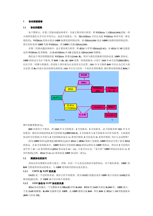
1协议阅读指南1.1协议的框架如下图所示,在第三代移动通讯体系中,目前主要有两大阵营,即WCDMA与CDMA2000(其他一些小的阵营我们几乎可以不用关心,此处不再提及。
另,TD-SCDMA可以认为是WCDMA阵营中的一种无线技术)。
WCDMA的协议是由3GPP标准化组织制定的,而CDMA2000是由3GPP2标准化组织制定的,所以有时也用3GPP代指WCDMA,用3GPP2代指CDMA2000。
在第二代移动通讯体制中,也主要有两大阵营,即GSM与窄带CDMA(IS-95)。
由GSM向3G过渡是走的WCDMA技术路线,由IS-95CDMA向3G过渡是走CDMA2000的路线。
我们这个项目将要做的是WCDMA的基站(Node B),所以与我们直接相关的协议是3GPP的协议。
3GPP的协议分为3个版本,即R99与R4、R5,R99是第一阶段的版本,计划于2000年6月定型(FROZEN),以后只作一些微小的修改,但实际上到目前为止还没有完全定型。
2001年3月版的R99可以认为已经大部分定型。
而R4目前正处在标准化的阶段,2001年3月已经有一个初步定型的规范。
我们要实现的就是R99(下图中加粗黑框部分)。
R99目前有5个版本,即2000年3月份版本、6月份版本、9月份版本、12月份版本和2001年3月份版本,我们应该阅读的是9月份的版本(3GPP2000.9),3月份版本与6月份版本可以作为参考。
大家阅读协议时可以看到,3月份与6月份的版本是从21系列开始的,9月份是从01系列开始的,为什么会这样呢?因为3GPP的协议(特别是CN侧协议)是在GSM与GPRS基础上发展的,3GPP的协议引用了很多GSM 的协议,在9月份的版本中,3GPP将部分引用到的GSM的协议转化为3GPP的协议,所以在9月份的目录中多了01~12系列的协议(GSM协议是从01~12)。
大家可以认为,“真正的”3GPP的协议还是从21系列开始的(当然,GSM的01~12系列也是3GPP协议的一部分)。
3GPP定义的WCDMA频谱

5 Frequency bands and channel arrangement 5.1 GeneralThe information presented in this subclause is based on a chip rate of 3.84 Mcps.NOTE: Other chip rates may be considered in future releases.5.2 Frequency bandsa) UTRA/FDD is designed to operate in the following paired bands:Table 5.0: UTRA FDD frequency bandsb) Deployment in other frequency bands is not precludedc) DB-DC-HSDPA is designed to operate in the following configurations:Table 5.0AA DB-DC-HSDPA configurations5.3 TX-RX frequency separationa) UTRA/FDD is designed to operate with the following TX-RX frequency separationTable 5.0A: TX-RX frequency separationb) UTRA/FDD can support both fixed and variable transmit to receive frequency separation.c) The use of other transmit to receive frequency separations in existing or other frequency bandsshall not be precluded.d) When configured to operate on dual cells in the DL with a single UL frequency, the TX-RXfrequency separation in Table 5.0A shall be applied for the serving HS-DSCH cell. For bands XII, XIII and XIV, the TX-RX frequency separation in Table 5.0A shall be the minimumspacing between the UL and either of the DL carriers.e) When configured to operate on dual cells in both the DL and UL, the TX-RX frequencyseparation in Table 5.0A shall be applied to the primary UL frequency and DLfrequency of the serving HS-DSCH cell, and to the secondary UL frequency and thefrequency of the secondary serving HS-DSCH cell respectively.f) For bands XII, XIII and XIV, all the requirements in TS 25.101 are applicable only fora single uplink carrier frequency, however dual cell uplink operation may be consideredin future releases.5.4 Channel arrangement5.4.1 Channel spacingThe nominal channel spacing is 5 MHz, but this can be adjusted to optimise performance in a particular deployment scenario. In DC-HSDPA and DB-DC-HSDPA mode, the UE receives two cells simultaneously. In context of DC-HSDPA and DB-DC-HSDPA, a cell is characterized by a combination of scrambling code and a carrier frequency, see [21.905].5.4.2 Channel rasterThe channel raster is 200kHz, for all bands which means that the centre frequency must be an integer multiple of 200 kHz. In addition a number of additional centre frequencies are specified according to table 5.1A, which means that the centre frequencies for these channels are shifted 100 kHz relative to the general raster.5.4.3 Channel numberThe carrier frequency is designated by the UTRA Absolute Radio Frequency Channel Number (UARFCN). For each operating Band, the UARFCN values are defined as follows:Uplink: N U =5 * (F UL - F UL_Offset), for the carrier frequency range F UL_low ≤ F UL ≤F UL_highDownlink: N D =5 * (F DL - F DL_Offset), for the carrier frequency range F DL_low ≤ F DL ≤ F DL_highFor each operating Band, F UL_Offset, F UL_low, F UL_high, F DL_Offset,, F DL_low and F DL_high are defined in Table5.1 for the general UARFCN. For the additional UARFCN, F UL_Offset, F DL_Offset and the specific F UL andF DL are defined in Table 5.1A.Table 5.1: UARFCN definition (general)Table 5.1A: UARFCN definition (additional channels)5.4.4 UARFCNThe following UARFCN range shall be supported for each paired bandTable 5.2: UTRA Absolute Radio Frequency Channel NumberNOTE: If the UE is on a network with Mobile Country Code set to Japan then it may assume that any DL UARFCN sent by the network from the overlapping region of Band V and BandVI is from Band VI. If the UE is on a network with a Mobile Country Code other thanJapan then it may assume that any DL UARFCN sent by the network from theoverlapping region of Band V and Band VI is from Band V.。
3GPP定义的WCDMA频谱

5 Frequency bands and channel arrangement 5.1 GeneralThe information presented in this subclause is based on a chip rate of 3.84 Mcps.NOTE: Other chip rates may be considered in future releases.5.2 Frequency bandsa) UTRA/FDD is designed to operate in the following paired bands:Table 5.0: UTRA FDD frequency bandsb) Deployment in other frequency bands is not precludedc) DB-DC-HSDPA is designed to operate in the following configurations:Table 5.0AA DB-DC-HSDPA configurations5.3 TX-RX frequency separationa) UTRA/FDD is designed to operate with the following TX-RX frequency separationTable 5.0A: TX-RX frequency separationb) UTRA/FDD can support both fixed and variable transmit to receive frequency separation.c) The use of other transmit to receive frequency separations in existing or other frequency bandsshall not be precluded.d) When configured to operate on dual cells in the DL with a single UL frequency, the TX-RXfrequency separation in Table 5.0A shall be applied for the serving HS-DSCH cell. For bands XII, XIII and XIV, the TX-RX frequency separation in Table 5.0A shall be the minimumspacing between the UL and either of the DL carriers.e) When configured to operate on dual cells in both the DL and UL, the TX-RX frequencyseparation in Table 5.0A shall be applied to the primary UL frequency and DLfrequency of the serving HS-DSCH cell, and to the secondary UL frequency and thefrequency of the secondary serving HS-DSCH cell respectively.f) For bands XII, XIII and XIV, all the requirements in TS 25.101 are applicable only fora single uplink carrier frequency, however dual cell uplink operation may be consideredin future releases.5.4 Channel arrangement5.4.1 Channel spacingThe nominal channel spacing is 5 MHz, but this can be adjusted to optimise performance in a particular deployment scenario. In DC-HSDPA and DB-DC-HSDPA mode, the UE receives two cells simultaneously. In context of DC-HSDPA and DB-DC-HSDPA, a cell is characterized by a combination of scrambling code and a carrier frequency, see [21.905].5.4.2 Channel rasterThe channel raster is 200kHz, for all bands which means that the centre frequency must be an integer multiple of 200 kHz. In addition a number of additional centre frequencies are specified according to table 5.1A, which means that the centre frequencies for these channels are shifted 100 kHz relative to the general raster.5.4.3 Channel numberThe carrier frequency is designated by the UTRA Absolute Radio Frequency Channel Number (UARFCN). For each operating Band, the UARFCN values are defined as follows:Uplink: N U =5 * (F UL - F UL_Offset), for the carrier frequency range F UL_low ≤ F UL ≤F UL_highDownlink: N D =5 * (F DL - F DL_Offset), for the carrier frequency range F DL_low ≤ F DL ≤ F DL_highFor each operating Band, F UL_Offset, F UL_low, F UL_high, F DL_Offset,, F DL_low and F DL_high are defined in Table5.1 for the general UARFCN. For the additional UARFCN, F UL_Offset, F DL_Offset and the specific F UL andF DL are defined in Table 5.1A.Table 5.1: UARFCN definition (general)Table 5.1A: UARFCN definition (additional channels)5.4.4 UARFCNThe following UARFCN range shall be supported for each paired bandTable 5.2: UTRA Absolute Radio Frequency Channel NumberNOTE: If the UE is on a network with Mobile Country Code set to Japan then it may assume that any DL UARFCN sent by the network from the overlapping region of Band V and BandVI is from Band VI. If the UE is on a network with a Mobile Country Code other thanJapan then it may assume that any DL UARFCN sent by the network from theoverlapping region of Band V and Band VI is from Band V.。
WCDMA R99核心网介绍

HLR接口 HLR接口
MP A TCA P
MP A TCA P
SCCP M TP3 M TP2
L1
SCCP M TP3 M TP2
L1
MSC/VLR接口 MSC/VLR接口
核心网络CS域(MSC/VLR)
• G口:VLR与VLR的接口,用于 VLR间信息交互,承载MAP信 令; • Gs口:VLR与SGSN的接口,用 于 VLR 与 SGSN 的 交 互 , 承 载 BSSAP+信令; • C 口 : MSC/GMSC 与 HLR 的 接 口,用于GMSC与HLR的交互, 这个接口只有信令,承载MAP 信令; • D口:VLR与HLR的接口,用于 HLR与VLR的交互,承载MAP 信令;
3GPP组织机构
• 3GPP分为项目合作部(PCG)和技术规范部 (TSG) • 业务和系统部(TSG SA)负责整个WCDMA 体系结构和业务方面的工作,包括安全性、 编解码器和电信管理 • 核心网络部(TSG CN)负责GSM和WCDMA 系统核心网络部分的规范工作;
3GPP组织机构
• 无线接入网络部(TSG RAN)负责WCDMA 的无线接入部分,包括体系结构和协议 • GSM EDGE无线接入网络部(TSG GERAN) • 终端部(TSG T) • 目标 3GPP的目标是实现由2G网络到3G网络的平 滑过渡,保证未来技术的后向兼容性,支持 轻松建网及系统间的漫游和兼容性。
核心网络PS域
• 用户提供“分 组型数据业 务”,PS域特 有的实体包括: SGSN GGSN
WCDMA 3GPP主要指标介绍

常见问题原因: 1、接收机异常
硬件研发部 24/28
Blocking Characteristics
---当存在特定频率(除去邻道频率和杂散响应频率)存在较强的干扰信号下,接收机 接收有用信号时,控制性能恶化的能力。 测试目的:大的Blocking信号进入接收机链路,接收机AGC因此产生动作降低增益以 确保动态范围;但是同时进入接收机的有用信号电平很低,此时增益不足,进入到 解调器的有用信号幅度不够。 带内阻塞(接收频段内或接收频段±15MHz以内),带外阻塞(接收频段 ±15MHz以外),窄带阻塞(GSM信号,频率位于标称信道间隔内)。如果阻塞指标 不好会降低通信距离,尤其在UE附近有其他用户在发射时。 指标要求: 常见问题原因: 1、平台芯片能力
Minimum Output Power
---该项测试的是手机的功率控制在最小功率时,手机的发射功率值。 测试目的:验证无线环境较好,且UE与基站很近时,UE能把自己的输出 功率降得很低,以确保对其它UE的最小干扰和对电池的最小消耗。 指标要求: 最小功率测试一个时隙的均值功率,门限要求不高于-49dBm。UE target power设置为-55dBm; UL CL Power Ctrl Mode 设 All down bits 常见问题原因: 1、此项出问题多出在功率切换点附近,多为射频参数配置问题 2、校准异常
常见问题原因: 1、此项出问题多出在功率切换点附近,多为射频参数配置问题 2、校准异常
硬件研发部 8/28
标准同时还规定了A,B,C,D,E,F,G,H 8段区域来测试,其中E段和F段是较容易出 现问题的两段,因为这两段的功率波动范围最大(Max-Min),且控制step比较 精细(1dB)
硬件研发部 9/28
3GPP常用英文缩写全称大全

3GPP常用英文缩写全称大全3G是3GPP的简写形式,3GPP在英文里的全称是:the 3rd Generation Partner Project 中文的全称是:第三代合作伙伴计划,是领先的3G技术规范机构,旨在研究制定并推广基于演进的GSM核心网络的3G标准,它负责WCDMA标准的制定,R4标准是其中较为成熟的一个版本。
3GPP:3GP是一种3G流媒体的视频编码格式,是目前手机中最为常见的一种视频格式。
简单的说,该格式是“第三代合作伙伴项目”(3GPP)制定的一种多媒体标准,使用户能使用手机享受高质量的视频、音频等多媒体内容。
3GPP常用英文缩写全称大全3GPP 3rd Generation Partnership ProjectAAL ATM Adaptation LayerAAL2 ATM Adaptation Layer of type 2AAL5 ATM Adaptation Layer of type 5A&C Authentication and CipheringACFE Access Control Function EntityAI Acquisition IndicationAICH Acquisition Indication ChannelALCAP Access Link Control Application PartAM Acknowledged Mode (of RLC)AMR Adaptive Multi Rate (Transcoder)AN Access NetworkAOA Angle Of ArrivalAP Application ProcessAPDU Application Protocol Data UnitAPId Access Point IdentifierAPN Access Point NameAPS Automatic Protection SwitchingARIB Association of Radio Industries and BusinessARQ Automatic Repeat RequestASAP Alarm Severity Assignment Pro ATM Transfer CapabilityATM Asynchronous Transfer ModeAUG Administrative Unit GroupAU-n Administrative Unit n with n being 4 or 3AUTN Authentication TokenAWGN Added White Gaussian NoiseBCCH Broadcast Control ChannelBCH Broadcast ChannelBER Bit Error RateBLER Block Error RateBMC Broadcast Multicast ControllerBPSK Binary Phase Shift KeyingBS Base StationBSC Base Station ControllerBSS Base Station SystemBTS Base Transceiver StationC- Control-CA Capacity AllocationCAA Capacity Allocation AcknowledgementCAC Connection Admission ControlCAMEL Customized Applications for Mobile network Enhanced Logic CAS Channel Associated SignallingCASC Current Alarm Summary ControlCBR Constant Bit RateCC Call ControlCCBS Call Completion Busy SubscriberCCCH Common Control ChannelCCH Control ChannelCCP Communication Control PortCCPCH Common Control Physical ChannelCCTrCH Coded Composite Transport ChannelCD Capacity Deallocation (radio context)CD Calibration Data (O&M context)CDA Capacity Deallocation AcknowledgementCDMA Code Division Multiple AccessCDR Charging Detail RecordCDV Cell Delay VariationCDVT Cell Delay Variation ToleranceCFN Connection Frame NumberCID Channel IdentifierCk Cipher KeyCLP Cell Loss PriorityCM Configuration ManagementCM Call Management (in e.g. CM Service Request)CmCH Common Transport ChannelCMIP Common Management Information ProtocolCMIS Common Management Information ServiceCMISE Common Management Information Service ElementCN Core NetworkC-n Container-n (n=1-4)COL Collocated EquipmentCP Chip PeriodCPCH Common Packet ChannelCPICH Common Pilot ChannelCPS Common Part SublayerCRC Cyclic Redundancy CheckCRCI CRC IndicatorCRC-N Cyclic Redundancy Check-NCRNC Controlling RNCc-RNTI RNTI allocated by CRNCCS Circuit SwitchedCSES Consecutive Severely Errored SecondCSN Ciphering Sequence NumberCSUM ChecksumCTCH Common Traffic ChannelCTDMA Code Time Division Multiple AccessCTP Connection Termination Point (OAM context)CTP Common Transport Protocol (Protocol context)DBR Deterministic Bit RateDC Dedicated Control (SAP)DCA Dynamic Channel AllocationDCCH Dedicated Control ChannelDCH Dedicated ChannelDCN Data Communication NetworkDL DownLinkDoCoMo Do Communication with MobilesDPCCH Dedicated Physical Control ChannelDPCH Dedicated Physical ChannelDPDCH Dedicated Physical Data ChannelDRAC Dynamic Resource Allocation ControlDRNC Drift RNCDRNS Drift RNSDRX Discontinuous ReceptionDS-CDMA Direct-Sequence Code Division Multiple Access DSCH Downlink Shared ChannelDT Data TransportDTCH Dedicated Traffic ChannelDTX Discontinuous TransmissionEBER Excessive Bit Error RatioECASC Extended Current Summary Alarm ControlEFCI Explicit Forward Congestion IndicationEFD Event Forwarding DiscriminatorEIR Equipment Identity RegisterEIRP Equivalent Isotropic Radiated PowerE-OTD Enhanced OTDES Errored SecondETSI European Telecommunication Standardisation Institute F8 access link encryption functionFACH Forward Access ChannelFAUSCH Fast Uplink Signalling ChannelFBI Feed Back IndicatorFCS Frame Check SequenceFDD Frequency Division DuplexFDMA Frequency Division Multiple AccessFEC Forward Error CorrectionFEEB Far End Errored BlockFEES Far End Errored SecondFER Frame Erasure RateFESES Far End Severely Errored SecondFFS For Further StudyFM Fault ManagementFP Frame ProtocolFTAM Access ManagementFTP ProtocolGb Gb interface (between SGSN and BSC)GC General Control (SAP)GCRA Generic Cell Rate AlgorithmGFR Guaranteed RateGGSN Gateway GPRS Serving NodeGMM MM for GPRS servicesGMSK Gaussian Minimum Shift KeyingG-PDU T-PDU plus GTP headerGPRS General Packet Radio ServiceGPRS-CSI GPRS CAMEL Subscription Information GPS Global Positioning SystemGRNC Generic RNCGSM Global System for Mobile communications GTP GPRS Tunnelling ProtocolGTP-u GTP user planeHCS Hierarchical Cell StructureHE Home EnvironmentHEC Header Error ControlHFN Hyper Frame NumberHHO Hard HandoverHO HandoverHOP High Order PathHOVC Higher Order Virtual ContainerIBTS uplink Interference signal power level at Node B ICB Inter Carrier BoardICD Interface Control DocumentICH Indicator CHannelICI Inter Carrier InterfaceIE Information ElementIEC Incoming Error CountIETF Internet Engineering Task ForceIK Integrity KeyIMA Inverse Multiplexing for ATMIMEI International Mobile Equipment IdentityIMEISV International Mobile Equipment Identity Software VersionIMSI International Mobile Subscriber Identity (identical for IMUI; used in GSM context)IMUI International Mobile User Identity (identical to IMSI; seems to replace IMSI in UMTS context) INI Inter Network InterfaceIP Internet ProtocolISCP Interference Signal Code PowerISDN Integrated Services Digital NetworkISF Incoming Signal FailureIS-FL Idle Slot Forward LinkISID Idle Signal IdentificationISO International Organisation for StandardizationIT Information TechnologyITU International Telecommunication UnionIu Reference point between Access and Serving Network domainsIub Iub interface (between Node B and RNC)Iu-CS Iu towards the Circuit Switched-Service Domain of the Core NetworkIu-PS Iu towards the Packet Switched-Service Domain of the Core NetworkIur Iur interface (between RNC and RNC)IWF Inter Working FunctionIWU Inter Working UnitJD Joint DetectionKbps kilo-bits per secondKSI Key Set IdentifierKsps kilo-symbols per secondL1 Layer 1 (physical layer)L2 Layer 2 (data link layer)L3 Layer 3 (network layer)L3-CE Layer 3 Compression EntityLAC Link Access ControlLAI Location Area IdentityLAN Local Area NetworkLAPD Link Access Protocol for D-channelLB Laser BiasLCAF Location Client Authorisation FunctionLCCF Location Client Control FunctionLCCTF Location Client Coordinate Transformation FunctionLCD Loss of Cell Delineation (transmission context)LCD Low Constrained Delay (traffic context)LCF Location Client FunctionLCS Localisation Client ServiceLDD Low Delay DataLIR Limited IP Routing entity (in the RNC)LLC Link Layer ControlLMT Local Maintenance TerminalLNA Low Noise AmplifierLOF Loss of FrameLOP Low Order PathLOP Loss of PointerLOS Loss of SignalLPA Linear Power AmplifierLSA Localised Service AreaLSB Least Significant BitLSBF Location System Billing FunctionLSCF Location System Control FunctionLSN Local Sub NetworkLSPF Location Subscriber Privacy FunctionLT Laser TemperatureLTOA Latest Time of ArrivalMA Multiple AccessMAC Medium Access ControlMAC-c MAC entity handling common channels (RACH, FACH)MAC-d MAC entity handling dedicated channels (DCH)MAC-I Message Authentication Code used for data Integrity of signalling messages MAC-sh MAC entity handling shared channel (DSCH)MAHO Mobile Assisted HandoverMBS Maximum Burst SizeMCC Mobile Country CodeMCD Manual Configuration DataMcps Mega-chips per secondMD Macro-diversityME Mobile EquipmentMEHO Mobile evaluated handoverMIB Management Information BaseMM Mobility ManagementMNC Mobile Network CodeMNRG Mobile station Not Reachable for GPRS flagMNRR Mobile station Not Reachable ReasonMO Mobile OriginatedMOHO Mobile Originated HandoverMS Multiplex Section (transmission context)MS Mobile Station (GSM or security context)MS-AIS Multiplex Section Alarm Indication SignalMSB Most Significant BitMSC Multi-Slot Cell (MPSR context)MSC Mobile services Switching Centre (Core Network Context) MSID Mobile Station IdentifierMSOH Multiplex Section OverheadMSP Multiplex Section ProtectionMS-RDI Multiplex Section Remote Defect IndicationMS-REI Multiplex Section Remote Error IndicationMSTE Multiplex Section Terminating ElementMT Mobile Terminated (call context)MT Mobile Terminal (equipment context)MTP Message Transfer PartMUI Mobile User IdentifierNAS Non Access StratumNBAP Node B Application PartNCP Node B Control PortNCSES Number of Consecutive Severely Errored Second NDF New Data FlagNE Network ElementNEHO Network evaluated handoverNEM Network Element ManagerNMC Network Management CentreNNI Network Node Interface (includes INI and ICI interfaces) NP Nectar PilotNPC Network Parameters ControlNRT Non-Real TimeNSS Network Sub SystemNT Nectar TelecomNt Notification (SAP)NW NetworkN-PDU Network PDUO&M Operation and MaintenanceOAM Operation Administration and MaintenanceOCCCH ODMA Common Control ChannelODCCH ODMA Dedicated Control ChannelODCH ODMA Dedicated ChannelODI Outgoing Defect IndicationODMA Opportunity Driven Multiple AccessODTCH ODMA Dedicated Traffic ChannelOEI Outgoing Error IndicationOFS Out of Frame SecondOMC Operation and Maintenance CentreOOF Out of FrameORACH ODMA Random Access ChannelOS Operation SystemOSF Offset FieldOSI Open System InterconnectionOSL Optical Signal LevelOTD Observed Time DifferenceOVSF Orthogonal Variable Spreading FactorPA Power AmplifierPC Power ControlPCCH Paging Control ChannelPCF Positioning Calculation FunctionPCH Paging ChannelPCM Pulse Code ModulationPCR Peak Cell RatePDCP Packet Data Convergence protocolPDH Plesiochronous Digital HierarchyPDN Packet Data NetworkPDP Packet Data ProtocolPDU Protocol Data UnitPG Processing GainPHY Physical layerPhyCH Physical ChannelPI Paging IndicatorPICH Page Indicator ChannelPID Packet IdentificationPJC Pointer Justification CountPJE Pointer Justification EventPkg PackagesPLM Payload MismatchPLMN Public Land Mobile NetworkPM Performance Management/Performance Monitoring PMM MM for PS domainPN Pseudo NoisePOH Path OverheadPPI Plesiochronous Physical InterfacePPM Parts Per MillionPRACH Physical Random Access ChannelPRCF Positioning Radio Co-ordination FunctionPS Packet SwitchedPSAP Presentation Service Access PointPSC Protection Switch CountPSD Protection Switch DurationPSMF Positioning Signal Measurement FunctionPSN Plane Switch NodePSTN Public Switched Telephone NetworkPTE Path Terminating ElementPVC Permanent Virtual ConnectionP-TMSI Packet TMSI (equivalent to P-TMUI, used in GPRS context)P-TMUI Packet TMUI – (equivalent to P-TMSI, new name for it in the UMTS context) PTR PointerPUF Power Up FunctionQE Quality EstimateQoS Quality of ServiceQPSK Quadrature Phase Shift KeyingRA Routing AreaRAB Radio Access BearerRAC Routing Area CodeRAC Radio Admission ControlRACH Random Access ChannelRAI Routing Area Identity (GPRS or Iu-PS context)RAI Remote Alarm Indication (transmission context)RAID Redundant Array of Independent DisksRAN Radio Access NetworkRANAP Radio Access Network Application PartRAND Random ChallengeRB Radio BearerRDI Remote Defect IndicationRDN Relative Distinguished NameREI Remote Error IndicationRF Radio FrequencyRFC Request For CommentRFN Reference Frame NumberRLC Radio Link ControlRLCP Radio Link Control ProtocolRLS Radio Link SetRLs Radio LinksRNC Radio Network ControllerRNCC Radio Network Connection ControlRNS Radio Network SubsystemRNSAP Radio Network Subsystem Application PartRNTI Radio Network Temporary IdentityRP Radio ProcessingRRC Radio Resource ControlRRM Radio Resource ManagementRS Regenerator sectionRSCP Received Signal Code Power after despreadingRSOH Regenerator Section OverheadRSSI Received Signal Strength IndicatorRT Real TimeRU Resource UnitRX ReceiveSAAL Signalling AAL (equivalent to SSCF over SSCOP over AAL5) SACCH Slow Associated Control ChannelSAP Service Access PointSBR Statistical Bit RateSC Service ControlSCCH Synchronization Control ChannelSCCP Signalling Connection Control PartSCD Selective Cell DiscardSCH Synchronization ChannelSCR Sustainable Cell RateSCTP Simple Control Transmission ProtocolSD Supervision Data (context configuration management)SD Signal Degrade (context SDH)SDCCH Stand-Alone Dedicated Control ChannelSDH Synchronous Digital HierarchySDU Service Data UnitSES Severely Errored SecondSF Signal Fail (transmission context)SF Spreading Factor (radio context)SFN System Frame NumberSG Study GroupSGSN Serving GPRS Support NodeSHO Soft Hand OverSIM Subscriber Information ModuleSIR Signal-to-Interference RatioSLM Signal Label MismatchSMS Short Message ServiceSN Serving NetworkSN Sequence NumberSNMP Simple Network Management ProtocolSOH Section OverheadSONET Synchronous Optical NetworkSP Switching PointSPA Signalling Point AccessibleSPI Signalling Point Inaccessible (SS7 context)SPI Synchronous Physical Interface (SDH context)SPROC System PROCessorSRNC Serving RNCSRNS Serving RNSs-RNTI RNTI allocated by SRNCSSA Signalling Subsystem AccessibleSSADT Service Specific Assured Data TransferSSCF Service Specific Coordination FunctionSSCOP Service Specific Connection-Oriented ProtocolSSP Signalling Subsystem ProhibitedSSSAR Service Specific Segmentation And ReassemblySSTED Service Specific Transmission Error DetectionSTF Start FieldSTM Synchronous Transport ModuleSTM(-N) Synchronous Transport Module (-N)STS(-N) Synchronous Transport Signal (-N)STTD Space Time Transmit DiversityTB Transport BlockTBC To Be ConfirmedTBD To Be DefinedTBF Transport Block FormatTBS Transport Block SetTCH Traffic ChannelTCM Tandem Connection MonitoringTCOH Tandem Connection OverheadTCP Transport Control ProtocolTCP Transport Control ProtocolTC-RDI Tandem Connection Remote Defect IndicationTC-REI Tandem Connection Remote Error IndicationTCT Tandem Connection TraceTCTE Tandem Connection Terminating ElementTDD Time Duplex DivisionTE Terminal EquipmentTEID Tunnel Endpoint IDTFCI Transport Format Combination IndicatorTFCS Transport Format Combination SetTFI Transport Format IndicatorTFS Transport Format SetTFT Traffic Flow TemplateTFTP Trivial ProtocolTIM Trace Identifier MismatchTLLI Temporary Logical Link IdentifierTM Transparent Mode (of RLC)TMN Telecommunication Management NetworkTMSI Temporary Mobile Subscriber Identity (used in GSM context, equivalent to TMUI) TMUI Temporary Mobile User Identity (new name for TMSI in the UMTS context)TN Termination NodeTOA or ToA Time Of ArrivalTOAWE TOA Window End pointTOAWS TOA Window Start pointTP Termination PointTPC Transmit Power ControlT-PDU Original packet, for example an IP datagram, from UE or an external PDNTR Threshold ResetTRX Transmitter/ReceiverTSID Test Signal IdentificationTSS Telecommunication Standardization SectorTTC Telecommunication Technology CommitteeTTI Time Transmission Interval (Radio Context)TTI Trail Trace Identifier (O&M context)TTP Trusted Third Party (security context)TTP Trail Termination Point (transmission context)TU Tributary UnitTUG Tributary Unit GroupTUG(-n) Tributary Unit Group (-n)TU-n Tributary Unit-nTX TransmitU- User-UARFCN UTRA Absolute Radio Frequency Channel NumberUAS Unavailable SecondUBR Unspecified Bit RateUDD Unconstrained Delay DataUDP User Datagram ProtocolUE User EquipmentUEA UMTS Encryption AlgorithmUEFN User Equipment Frame NumberUIA UMTS Integrity AlgorithmUL UpLinkUM Unacknowledged Mode (of RLC)UMTS Universal Mobile Telecommunication SystemUNEQ UnequippedUNI User to Network InterfaceUP User PlaneUPC Usage Parameters ControlURA User Registration AreaUSCH Uplink Shared CHannelUSIM UMTS Subscriber Identity ModuleUTRA UMTS Terrestrial Radio AccessUTRAN UMTS Terrestrial Radio Access NetworkUu Reference point between User Equipment and Infrastructure domains, UMTS radio interface UUI User to User IndicatorVA Voice Activity (factor)VBR Variable Bit RateVC Virtual ChannelVCC Virtual Channel ConnectionVCI Virtual Channel IdentifierVC-n Virtual Container n (n is 11, 12, 2, 3 or 4)VLR Visitor Location RegisterVP Virtual PathVPC Virtual Path ConnectionVPI Virtual Path IdentifierW-CDMA Wideband CDMAWG Working GroupWG-n Working Group (of 3GPP)WTR Wait-to-RestoreXMAC-I eXpected Message Authentication Code used for data Integrity of signalling messages XOR eXclusive ORXPU AuXiliary Processing UnitXRES Expected Response。
3GPP WCDMA
20 0 2年 9月 第 9期
3 P WCD GP MA 系统 技 术 特 点 和 标 准 状 况
维普资讯
互
0
2.14 1
万
WC MA 系 统标 准 目前 已有 R 9R , 5三 个 版 D 9 , 4R 本 , 中最新 的 R 其 5版 本 于 2 0 o 2年 6月 完 成 。 这 三 个版本各有特色 。
符合 3 P G P规 范 的 WC MA 系统 关 键 技 术 涵 盖 以下 六 个 方 面 : D
1 CD . MA 技 术
wC DMA 系统 包 含 了很 多 C MA 的关 键 技 术 , 软 切 换 、 软切 换 、 率 控 制 等 。从 话 音 D 如 更 功 业 务 的 角 度 来 说 , DMA 系统 上行 仍 然 受 限 。从 无 线 网络 规 划 角 度 而 言 , DMA 与 GS WC WC M 有 本 质 的 区别 。同 时 , 由于 WC DMA来 源 于 C MA, 容 量 由误 块 率 控 制 , 以 WC MA 仍 包 D 其 所 D
。
5。
c D
R9 9接 入 部 分 主 要 定 义 了 全 新 每 载 频 5MH z
的宽 带 C DMA 接 入 网 , 纳 了 功 率 控 制 、 切 换 及 采 软
分组话音分 布式体系结构 ;
基于3gpp协议的wcdma网络脆弱性研究

摘要摘要WCDMA网络已经非常成熟,但是有针对目标的侦察与干扰的研究仍然是亟待解决的研究课题。
本文结合XXX项目,针对干扰特定目标的问题,重点分析了WCDMA网络的协议脆弱性,并提出有特定目标的新型攻击方案。
本文依据3GPP TS RRC协议以及物理层协议,对WCDMA网络进行了脆弱性分析。
本文的主要工作如下:1.对WCDMA系统中使用的典型加密算法––––Kasumi算法进行了分析,使用相关密钥Sandwich攻击算法对其进行攻击,并通过调整明文对选择规则的方法,对Sandwich算法中的7轮区分器进行了改进。
对改进后的攻击算法进行了计算机仿真,仿真结果表明:改进的区分器降低了攻击算法的存储复杂度。
2.针对Sandwich攻击所需的条件较为苛刻,攻击需耗费庞大的时间成本和硬件成本以及改进的Sandwich攻击仍然难以实现等局限,本文结合RRC协议对随机接入过程进行脆弱性分析,提出了针对随机接入过程的伪基站攻击方案并对该方案进行了仿真。
仿真结果表明:在该攻击方案下,目标用户将舍弃真实基站,转而与伪基站进行通信,与此同时,普通用户仍然可以与真实基站进行正常通信。
3.使用C语言重写伪基站攻击方案的关键攻击模块,并进行软件仿真。
仿真结果与Matlab结果吻合,保证了攻击模块逻辑的正确性。
本文使用CCS5.5进行开发,目的是考虑到未来可能使用无人机搭载DSP进行攻击。
关键字:WCDMA,随机接入过程,伪基站攻击方案,Kasumi算法,相关密钥Sandwich攻击算法ABSTRACTABSTRACTTargeted interference in WCDMA network is a science problem which can not wait to be solved. In this thesis, a new attack plan with a specific target has been proposed by analyzing the protocal vulnerability of WCDMA network. The new attack plan is based on the XXX project which aims at obtaining the solution of targeted interference.The analyzing is based on the 3GPP TS RRC protocol and physical layer protocol. The main content of this article is as follows:1.The classic Kasumi algorithm which plays an important role in WCDMA network has been analyzed in this thesis. The Kasumi-targeted attack–––related key Sandwich attack has been simulated to attack Kasumi algorithm. This thesis shows a way to improve the 7-round Kasumi discriminator by adjusting the rule of how to choose plaintext. The simulation result shows that the improved discriminator can reduce the storage complexity of the attack algorithm.2.Because Sandwich attack requires harsh condion–––lots of time and expensive hardware, it is difficult to implement the attack even the improved version. A better breakthrough point is the random access process. A pseudo station attack plan which targets the random access process have been showed in this thesis. The pseudo station attack is based on the RRC protocol and its simulation result shows that the target will discard the real station while the ordinary user communicates with the real station normally.3.The pseudo station attack’s critical module has been rewritten by C language in this thesis. The C code has been runned in the software condition––––CCS5.5. The CCS5.5 software simulation has the same result with Matlab simulation. The similarity ensures the correctness of the attack module logic. The purpose of coding in C language is to take the possibility of implementing the future attack with DSP-loaded UA V into consideration.Keywords: WCDMA, random access procedure, Kasumi algorithm, related key Sandwich attack algorithm目录第一章绪论 (1)1.1 研究背景与意义 (1)1.2 WCDMA网络安全防护概述 (1)1.3 WCDMA网络攻击概述 (3)1.4 本文主要内容与结构安排 (4)第二章Kasumi算法基础 (5)2.1 Kasumi算法在WCDMA网络中的应用 (5)2.2 Kasumi算法分析 (8)2.2.1 FL函数分析 (9)2.2.2 FO、FI函数分析 (11)2.2.3 密钥扩展算法 (14)2.3 本章小结 (14)第三章相关密钥Sandwich攻击算法及改进 (15)3.1 当前Kasumi加密算法攻击现状 (15)3.2 差分密码分析概述 (16)3.3 相关密钥Sandwich攻击概述 (17)3.3.1 相关密钥Boomerang攻击 (17)3.3.2 相关密钥Sandwich攻击 (19)3.4 七轮Kasumi算法的Sandwich区分器分析 (20)3.4.1 三轮Kasumi算法区分器分析 (21)3.4.2 第四轮Kasumi算法区分器分析 (22)3.5 Sandwich区分器仿真结果 (25)3.6 八轮Kasumi算法攻击步骤 (28)3.7 七轮Kasumi算法区分器改进 (30)3.8 本章小结 (32)第四章随机接入过程脆弱性分析 (33)4.1 移动通信网络的相关结构概述 (33)4.2 RRC(无线资源控制)的相关概念 (33)4.2.1 RRC状态和状态转移 (34)4.3 信道类型及其映射关系 (34)4.3.1 逻辑信道 (34)4.3.2 传输信道 (35)4.3.3 物理信道 (36)4.3.4 信道之间的映射关系 (36)4.4 随机接入过程详解 (37)4.4.1 同步过程 (37)4.4.2 同步码的产生与分配 (38)4.4.3 与接入过程有关的资源 (39)4.4.4 信道码的产生 (40)4.4.5 扰码的产生 (41)4.4.6 PRACH与AICH的接入时隙时间偏移 (43)4.4.7 PRACH的接入前导(Preamble)部分 (44)4.4.8 AICH的回应机制 (44)4.4.9 随机接入流程 (45)4.5 物理层功能 (48)4.6 物理层数据处理流程 (49)4.6.1 信道编码 (49)4.6.2 交织 (49)4.6.3 扩频、加扰和调制 (49)4.7 物理信道结构 (50)4.7.1 基本公共控制信道 (50)4.7.2 同步信道 (51)4.7.3 公共导频信道 (51)4.7.4 随机接入信道 (52)4.8 盲自适应多用户检测 (52)4.8.1 信号模型 (53)4.8.2 盲多用户检测器的典范表示 (53)4.8.3 基于最小输出能量准则的多用户检测 (54)4.9 多用户的随机接入过程仿真 (56)4.9.1 仿真流程 (56)4.9.2 小区广播、导频信号与同步信号仿真 (57)4.9.3 UE接入前导的发送 (63)4.9.4 接入应答信号的发送与接收 (65)4.9.5 RACH Message的发送与接收 (67)4.10 针对随机接入过程的伪基站攻击方案仿真 (71)4.10.1 仿真流程 (71)4.10.2 广播篡改 (72)4.10.3 UE接收广播信号 (74)4.10.4 接入前导与应答信号 (75)4.10.5 RACH消息的发送与接收 (76)4.11 针对随机接入过程的伪基站攻击与现有攻击的比较 (78)4.11.1 3G网络信令攻击简介 (79)4.11.2 信令攻击与针对随机接入过程的伪基站攻击对比 (79)4.11.3 传统伪基站攻击简介 (79)4.11.4 传统伪基站攻击与针对随机接入过程的伪基站攻击对比 (80)4.11.5 中间人攻击简介 (81)4.11.6 中间人攻击与针对随机接入过程的伪基站攻击对比 (81)4.12 本章小结 (82)第五章C语言重写仿真核心模块 (83)5.1 开发板简介 (83)5.2 分模块的C语言实现 (83)5.2.1 QPSK调制与解调模块 (84)5.2.2 盲自适应多用户检测模块 (87)5.2.3 加扰解扰模块以及交织解交织模块 (88)5.2.4 卷积模块与维特比译码 (90)5.3 同步模块的实现 (92)5.4 广播信号接收与篡改模块的实现 (95)5.5 本章小结 (98)第六章总结与展望 (99)6.1 文章工作总结 (99)6.2 本文的不足之处 (99)6.3 下一步研究工作 (100)致谢 (101)参考文献 (102)个人简历及攻读硕士学位期间取得的成果 (105)第一章绪论第一章绪论1.1研究背景与意义在移动通信的发展历程中,随着用户对无线通信的业务需求不断增长,第三代通信系统得到了迅猛的发展,该系统能够提供种类各异的服务,可实现数据的高速传输,保证了高质量的多媒体业务[1]。
第18章WCDMA3GPP通信系统设计
下行信道中采用公共连续导频方式进行相干检测,提高系统容量;
在下行信道传输中,定义直扩和多载波传输两种方式,码片速率分别为3.6864Mchip/s和 1.22Mchip/s,多载波方式能很好地兼容IS-95网络; 支持F-QPCH,可延长手机待机时间; 核心网络基于ANSI-41网络的演进,并保持与ANSI-41网络的兼容性; 支持软切换和硬软切换;
TD-SCDMA系统比较适合用于人口密度高,频率资源紧张,移动速度要求不是很高,但需 要大量小半径、高容量的小区覆盖的地区。同时在这些地区数据业务,特别是Internet等 非对称数据业务的需求比较大时,TD-SCDMA更能够充分发挥其技术优势。
1. W-CDMA W-CDMA的主要技术指标是:支持高速数据传输(慢速移动时384Kbit/s,室内走动时 2Mbit/s),异步BS,支持可变速传输,帧长10ms,码片速率3.84Mbit/s。 其主要特点如下:
基站同步方式,支持异步和同步的基站运行方式,组网方便、灵活;
调制方式,上行为BPSK,下行为QPSK,解调方式为导频辅助的相干解调; 接入方式为DS-CDMA方式; 采用三种编码方式,在语音信道采用卷积码(R=1/3,k=9)进行内部编码和Veterbi解码, 在数据信道采用Reed Solomon编码,在控制信道采用卷积码(R=1/2,k=9)进行内部编码 和Veterbi解码;
适应多种速率的传输,可灵活地提供多种业务,并根据不同的业务质量和业务速率分配不 同的资源,同时对多速率、多媒体的业务可通过改变扩频比(对于低速率的32Kbit/s、 64Kbit/s、128Kbit/s的业务)和多码并行传送(对于高于128Kbit/s的业务)的方式来实现;
- 1、下载文档前请自行甄别文档内容的完整性,平台不提供额外的编辑、内容补充、找答案等附加服务。
- 2、"仅部分预览"的文档,不可在线预览部分如存在完整性等问题,可反馈申请退款(可完整预览的文档不适用该条件!)。
- 3、如文档侵犯您的权益,请联系客服反馈,我们会尽快为您处理(人工客服工作时间:9:00-18:30)。
3GPP TS 34.121-1 V8.8.0 (2009-09)Technical Specification3rd Generation Partnership Project;Technical Specification Group Radio Access Network;User Equipment (UE) conformance specification;Radio transmission and reception (FDD);Part 1: Conformance specification(Release 8)The present document has been developed within the 3rd Generation Partnership Project (3GPP TM) and may be further elaborated for the purposes of 3GPP. The present document has not been subject to any approval process by the 3GPP Organizational Partners and shall not be implemented.This Specification is provided for future development work within 3GPP only. The Organizational Partners accept no liability for any use of this Specification. Specifications and reports for implementation of the 3GPP TM system should be obtained via the 3GPP Organizational Partners' Publications Offices.KeywordsTesting, UMTS3GPPPostal address3GPP support office address650 Route des Lucioles - Sophia AntipolisValbonne - FRANCETel.: +33 4 92 94 42 00 Fax: +33 4 93 65 47 16InternetCopyright NotificationNo part may be reproduced except as authorized by written permission.The copyright and the foregoing restriction extend to reproduction in all media.© 2009, 3GPP Organizational Partners (ARIB, ATIS, CCSA, ETSI, TTA, TTC).All rights reserved.Change the copyright date above as necessary.UMTS™ is a Trade Mark of ETSI registered for the benefit of its members3GPP™ is a Trade Mark of ETSI registered for the benefit of its Members and of the 3GPP Organizational PartnersLTE™ is a Trade Mark of ETSI currently being registered for the benefit of i ts Members and of the 3GPP Organizational Partners GSM® and the GSM logo are registered and owned by the GSM AssociationContents Foreword (36)Introduction (36)1Scope (37)2References (37)3Definitions, symbols, abbreviations and equations (38)3.1Definitions (38)3.2Symbols (39)3.3Abbreviations (39)3.4Equations (41)4Frequency bands and channel arrangement (43)4.1General (43)4.2Frequency bands (43)4.3TX–RX frequency separation (43)4.4Channel arrangement (44)4.4.1Channel spacing (44)4.4.2Channel raster (44)4.4.3Channel number (44)4.4.4UARFCN (46)4A Reference Conditions (47)4A.1Generic setup procedures (47)4A.2System information (47)4A.3Message contents (48)4A.4Measurement configurations (48)5Transmitter Characteristics (49)5.1General (49)5.2Maximum Output Power (49)5.2.1Definition and applicability (49)5.2.2Minimum Requirements (50)5.2.3Test purpose (50)5.2.4Method of test (50)5.2.4.1Initial conditions (50)5.2.4.2Procedure (50)5.2.5Test requirements (50)5.2A Maximum Output Power with HS-DPCCH (Release 5 only) (51)5.2A.1Definition and applicability (51)5.2A.2Minimum Requirements (51)5.2A.3Test purpose (52)5.2A.4Method of test (52)5.2A.4.1Initial conditions (52)5.2A.4.2Procedure (52)5.2A.5Test requirements (53)5.2AA Maximum Output Power with HS-DPCCH (Release 6 and later) (53)5.2AA.1Definition and applicability (53)5.2AA.2Minimum Requirements (53)5.2AA.3Test purpose (54)5.2AA.4Method of test (54)5.2AA.4.1Initial conditions (54)5.2AA.4.2Procedure (55)5.2AA.5Test requirements (55)5.2B Maximum Output Power with HS-DPCCH and E-DCH (55)5.2B.1Definition and applicability (55)5.2B.2Minimum Requirements (55)5.2B.3Test purpose (56)5.2B.4Method of test (56)5.2B.5Test requirements (59)5.2C UE relative code domain power accuracy (59)5.2C.1Definition and applicability (59)5.2C.2Minimum Requirements (60)5.2C.3Test purpose (60)5.2C.4Method of test (60)5.2C.4.1Initial conditions (60)5.2C.4.2Procedure (60)5.2C.5Test requirements (61)5.2D UE Relative Code Domain Power Accuracy for HS-DPCCH and E-DCH (62)5.2D.1Definition and applicability (62)5.2D.2Minimum Requirements (63)5.2D.3Test purpose (63)5.2D.4Method of test (63)5.2D.4.1Initial conditions (63)5.2D.4.2Procedure (65)5.2D.5Test requirements (66)5.2E UE Relative Code Domain Power Accuracy for HS-DPCCH and E-DCH with 16QAM (66)5.2E.1Definition and applicability (66)5.2E.2Minimum Requirements (67)5.2E.3Test purpose (67)5.2E.4Method of test (67)5.2E.4.1Initial conditions (67)5.2E.4.2Procedure (68)5.2E.5Test requirements (69)5.3Frequency Error (69)5.3.1Definition and applicability (69)5.3.2Minimum Requirements (70)5.3.3Test purpose (70)5.3.4Method of test (70)5.3.5Test Requirements (70)5.4Output Power Dynamics in the Uplink (70)5.4.1Open Loop Power Control in the Uplink (71)5.4.1.1Definition and applicability (71)5.4.1.2Minimum requirements (71)5.4.1.3Test purpose (71)5.4.1.4Method of test (71)5.4.1.5Test requirements (72)5.4.2Inner Loop Power Control in the Uplink (73)5.4.2.1Definition and applicability (73)5.4.2.2Minimum requirements (73)5.4.2.3Test purpose (74)5.4.2.4Method of test (74)5.4.2.5Test requirements (78)5.4.3Minimum Output Power (80)5.4.3.1Definition and applicability (80)5.4.3.2Minimum Requirements (80)5.4.3.3Test purpose (80)5.4.3.4Method of test (80)5.4.3.5Test requirements (81)5.4.4Out-of-synchronisation handling of output power (81)5.4.4.1Definition and applicability (81)5.4.4.2Minimum Requirements (81)5.4.4.3Test purpose (83)5.4.4.4Method of test (83)5.4.4.5Test requirements (84)5.5Transmit ON/OFF Power (84)5.5.1Transmit OFF Power (84)5.5.1.1Definition and applicability (84)5.5.1.2Minimum Requirements (84)5.5.1.5Test requirements (84)5.5.2Transmit ON/OFF Time mask (85)5.5.2.1Definition and applicability (85)5.5.2.2Minimum requirements (85)5.5.2.3Test purpose (87)5.5.2.4Method of test (87)5.5.2.5Test requirements (89)5.6Change of TFC (89)5.6.1Definition and applicability (89)5.6.2Minimum requirements (89)5.6.3Test purpose (91)5.6.4Method of test (91)5.6.5Test requirements (91)5.7Power setting in uplink compressed mode (92)5.7.1Definition and applicability (92)5.7.2Minimum requirements (92)5.7.3Test purpose (94)5.7.4Method of test (94)5.7.5Test requirements (102)5.7A HS-DPCCH power control (104)5.7A.1Definition and applicability (104)5.7A.2Minimum requirement (104)5.7A.3Test purpose (105)5.7A.4Method of test (105)5.7A.5Test requirements (106)5.8Occupied Bandwidth (OBW) (108)5.8.1Definition and applicability (108)5.8.2Minimum Requirements (108)5.8.3Test purpose (108)5.8.4Method of test (108)5.8.5Test Requirements (109)5.9Spectrum emission mask (109)5.9.1Definition and applicability (109)5.9.2Minimum Requirements (109)5.9.3Test purpose (111)5.9.4Method of test (111)5.9.4.1Initial conditions (111)5.9.4.2Procedure (111)5.9.5Test requirements (111)5.9A Spectrum Emission Mask with HS-DPCCH (113)5.9A.1Definition and applicability (113)5.9A.2Minimum Requirements (113)5.9A.3Test purpose (114)5.9A.4Method of test (115)5.9A.4.1Initial conditions (115)5.9A.4.2Procedure (115)5.9A.5Test requirements (115)5.9B Spectrum Emission Mask with E-DCH (117)5.9B.1Definition and applicability (117)5.9B.2Minimum Requirements (117)5.9B.3Test purpose (118)5.9B.4Method of test (118)5.9B.4.1Initial conditions (118)5.9B.4.2Procedure (119)5.9B.5Test requirements (119)5.10Adjacent Channel Leakage Power Ratio (ACLR) (121)5.10.1Definition and applicability (121)5.10.2Minimum Requirements (121)5.10.3Test purpose (121)5.10.4Method of test (121)5.10.5Test requirements (122)5.10A Adjacent Channel Leakage Power Ratio (ACLR) with HS-DPCCH (122)5.10A.1Definition and applicability (122)5.10A.2Minimum Requirements (122)5.10A.3Test purpose (122)5.10A.4Method of test (123)5.10A.5Test requirements (124)5.10B Adjacent Channel Leakage Power Ratio (ACLR) with E-DCH (124)5.10B.1Definition and applicability (124)5.10B.2Minimum Requirements (124)5.10B.3Test purpose (124)5.10B.4Method of test (125)5.10B.5Test requirements (126)5.11Spurious Emissions (126)5.11.1Definition and applicability (126)5.11.2Minimum Requirements (126)5.11.3Test purpose (128)5.11.4Method of test (129)5.11.5Test requirements (129)5.12Transmit Intermodulation (132)5.12.1Definition and applicability (132)5.12.2Minimum Requirements (132)5.12.3Test purpose (132)5.12.4Method of test (132)5.12.5Test requirements (133)5.13Transmit Modulation (133)5.13.1Error Vector Magnitude (EVM) (133)5.13.1.1Definition and applicability (133)5.13.1.2Minimum Requirements (133)5.13.1.3Test purpose (134)5.13.1.4Method of test (134)5.13.1.5Test requirements (134)5.13.1A Error Vector Magnitude (EVM) with HS-DPCCH (134)5.13.1A.1Definition and applicability (134)5.13.1A.2Minimum Requirements (135)5.13.1A.3Test purpose (135)5.13.1A.4Method of test (135)5.13.1A.5Test requirements (137)5.13.1AA Error Vector Magnitude (EVM) and phase discontinuity with HS-DPCCH (137)5.13.1AA.1Definition and applicability (137)5.13.1AA.2Minimum Requirements (137)5.13.1AA.3Test purpose (138)5.13.1AA.4Method of test (138)5.13.1AA.5Test requirements (140)5.13.1AAA EVM and IQ origin offset for HS-DPCCH and E-DCH with 16 QAM (140)5.13.1AAA.1Definition and applicability (140)5.13.1AAA.2Minimum requirement (141)5.13.1AAA.3Test purpose (142)5.13.1AAA.4Method of test (142)5.13.1AAA.5Test requirements (143)5.13.2 Peak code domain error (144)5.13.2.1Definition and applicability (144)5.13.2.2Minimum Requirements (144)5.13.2.3Test purpose (144)5.13.2.4Method of test (144)5.13.2.5Test requirements (145)5.13.2A Relative Code Domain Error with HS-DPCCH (145)5.13.2A.1Definition and applicability (145)5.13.2A.2Minimum Requirements (145)5.13.2A.3Test purpose (146)5.13.2A.4Method of test (146)5.13.2B Relative Code Domain Error with HS-DPCCH and E-DCH (148)5.13.2B.3Test purpose (149)5.13.2B.4Method of test (149)5.13.2B.5Test requirements (151)5.13.2C Relative Code Domain Error for HS-DPCCH and E-DCH with 16QAM (152)5.13.2C.1Definition and applicability (152)5.13.2C.2Minimum Requirements (153)5.13.2C.3Test purpose (154)5.13.2C.4Method of test (154)5.13.2C.5Test requirements (155)5.13.3UE phase discontinuity (157)5.13.3.1Definition and applicability (157)5.13.3.2Minimum requirements (157)5.13.3.3Test purpose (158)5.13.3.4Method of test (158)5.13.3.5Test requirements (159)5.13.4PRACH preamble quality (160)5.13.4.1Definition and applicability (160)5.13.4.2Minimum requirements (160)5.13.4.3Test purpose (160)5.13.4.4Method of test (160)5.13.4.5Test requirements (161)6Receiver Characteristics (162)6.1General (162)6.2Reference Sensitivity Level (163)6.2.1Definition and applicability (163)6.2.2Minimum Requirements (163)6.2.3Test purpose (163)6.2.4Method of test (163)6.2.5Test requirements (164)6.2A Reference Sensitivity Level for DC-HSDPA (164)6.2A.1Definition and applicability (164)6.2A.2Minimum Requirements (164)6.2A.3Test purpose (165)6.2A.4Method of test (165)6.2A.5Test requirements (166)6.3Maximum Input Level (166)6.3.1Definition and applicability (166)6.3.2Minimum requirements (166)6.3.3Test purpose (166)6.3.4Method of test (166)6.3.5Test requirements (167)6.3A Maximum Input Level for HS-PDSCH Reception (16QAM) (168)6.3A.1Definition and applicability (168)6.3A.2Minimum requirements (168)6.3A.3Test purpose (168)6.3A.4Method of test (168)6.3A.5Test requirements (169)6.3B Maximum Input Level for HS-PDSCH Reception (64QAM) (169)6.3B.1Definition and applicability (169)6.3B.2Minimum requirements (169)6.3B.3Test purpose (170)6.3B.4Method of test (170)6.3B.5Test requirements (172)6.3C Maximum Input Level for DC-HSDPA Reception (16QAM) (172)6.3C.1Definition and applicability (172)6.3C.2Minimum requirements (172)6.3C.3Test purpose (173)6.3C.4Method of test (173)6.3C.5Test requirements (173)6.3D.2Minimum requirements (174)6.3D.3Test purpose (175)6.3D.4Method of test (175)6.3D.5Test requirements (175)6.4Adjacent Channel Selectivity (ACS) (Rel-99 and Rel-4) (176)6.4.1Definition and applicability (176)6.4.2Minimum Requirements (176)6.4.3Test purpose (176)6.4.4Method of test (176)6.4.5Test requirements (177)6.4A Adjacent Channel Selectivity (ACS) (Rel-5 and later releases) (177)6.4A.1Definition and applicability (177)6.4A.2Minimum Requirements (177)6.4A.3Test purpose (178)6.4A.4Method of test (178)6.4A.5Test requirements (178)6.4B Adjacent Channel Selectivity (ACS) for DC-HSDPA (179)6.4B.1Definition and applicability (179)6.4B.2Minimum Requirements (179)6.4B.3Test purpose (180)6.4B.4Method of test (180)6.4B.5Test requirements (180)6.5Blocking Characteristics (181)6.5.1Definition and applicability (181)6.5.2Minimum Requirements (181)6.5.2.1Minimum Requirements (In-band blocking) (181)6.5.2.2Minimum requirements (Out of-band blocking) (182)6.5.2.3Minimum requirements (Narrow band blocking) (185)6.5.3Test purpose (185)6.5.4Method of test (185)6.5.5Test requirements (186)6.5A Blocking Characteristics for DC-HSDPA (189)6.5A.1Definition and applicability (189)6.5A.2Minimum Requirements (190)6.5A.2.1Minimum Requirements (In-band blocking) (190)6.5A.2.2Minimum requirements (Out of-band blocking) (191)6.5A.2.3Minimum requirements (Narrow band blocking) (193)6.5A.3Test purpose (193)6.5A.4Method of test (193)6.5A.5Test requirements (194)6.6Spurious Response (197)6.6.1Definition and applicability (197)6.6.2Minimum Requirements (197)6.6.3Test purpose (198)6.6.4Method of test (198)6.6.5Test requirements (198)6.6A Spurious Response for DC-HSDPA (199)6.6A.1Definition and applicability (199)6.6A.2Minimum Requirements (199)6.6A.3Test purpose (199)6.6A.4Method of test (200)6.6A.5Test requirements (200)6.7Intermodulation Characteristics (200)6.7.1Definition and applicability (200)6.7.2Minimum Requirements (201)6.7.3Test purpose (201)6.7.4Method of test (202)6.7.5Test requirements (202)6.7A Intermodulation Characteristics for DC-HSDPA (203)6.7A.1Definition and applicability (203)6.7A.2Minimum Requirements (203)6.7A.3Test purpose (204)6.7A.4Method of test (204)6.7A.5Test requirements (205)6.8Spurious Emissions (206)6.8.1Definition and applicability (206)6.8.2Minimum Requirements (206)6.8.3Test purpose (208)6.8.4Method of test (209)6.8.5Test requirements (209)7Performance requirements (214)7.1General (214)7.1.1Measurement Configurations (214)7.1.2Definition of Additive White Gaussian Noise (AWGN) Interferer (214)7.2Demodulation in Static Propagation conditions (215)7.2.1Demodulation of Dedicated Channel (DCH) (215)7.2.1.1Definition and applicability (215)7.2.1.2Minimum requirements (215)7.2.1.3Test purpose (215)7.2.1.4Method of test (215)7.2.1.5Test requirements (216)7.3Demodulation of DCH in Multi-path Fading Propagation conditions (216)7.3.1Single Link Performance (216)7.3.1.1Definition and applicability (216)7.3.1.2Minimum requirements (217)7.3.1.3Test purpose (219)7.3.1.4Method of test (219)7.3.1.5Test requirements (219)7.4Demodulation of DCH in Moving Propagation conditions (222)7.4.1Single Link Performance (222)7.4.1.1Definition and applicability (222)7.4.1.2Minimum requirements (222)7.4.1.3Test purpose (223)7.4.1.4Method of test (223)7.4.1.5Test requirements (223)7.5Demodulation of DCH in Birth-Death Propagation conditions (224)7.5.1Single Link Performance (224)7.5.1.1Definition and applicability (224)7.5.1.2Minimum requirements (224)7.5.1.3Test purpose (224)7.5.1.4Method of test (224)7.5.1.5Test requirements (225)7.5A Demodulation of DCH in high speed train condition (225)7.5A.1Single Link Performance (225)7.5A.1.1Definition and applicability (225)7.5A.1.2Minimum requirement (225)7.5A.1.3Test purpose (226)7.5A.1.4Method of test (226)7.5A.1.5Test requirements (226)7.6Demodulation of DCH in downlink Transmit diversity modes (227)7.6.1Demodulation of DCH in open-loop transmit diversity mode (227)7.6.1.1Definition and applicability (227)7.6.1.2Minimum requirements (227)7.6.1.3Test purpose (227)7.6.1.4Method of test (227)7.6.1.5Test Requirements (228)7.6.2Demodulation of DCH in closed loop transmit diversity mode (229)7.6.2.1Definition and applicability (229)7.6.2.2Minimum requirements (229)7.6.2.3Test purpose (230)7.6.2.4Method of test (230)7.6.2.5Test Requirements (231)7.6.3Demodulation of DCH in Site Selection Diversity Transmission Power Control mode (232)7.6.3.1Definition and applicability (232)7.6.3.2Minimum requirements (232)7.6.3.3Test purpose (233)7.6.3.4Method of test (233)7.6.3.5Test Requirements (236)7.7Demodulation in Handover conditions (237)7.7.1Demodulation of DCH in Inter-Cell Soft Handover (Release 5 and earlier) (237)7.7.1.1Definition and applicability (237)7.7.1.2Minimum requirements (237)7.7.1.3Test purpose (238)7.7.1.4Method of test (238)7.7.1.5Test requirements (238)7.7.1A Demodulation of DCH in Inter-Cell Soft Handover (Release 6 and later) (239)7.7.1A.1Definition and applicability (239)7.7.1A.2Minimum requirements (239)7.7.1A.3Test purpose (240)7.7.1A.4Method of test (240)7.7.1A.5Test requirements (240)7.7.2Combining of TPC commands from radio links of different radio link sets (241)7.7.2.1Definition and applicability (241)7.7.2.2Minimum requirements (241)7.7.2.3Test purpose (242)7.7.2.4Method of test (242)7.7.2.5Test requirements (243)7.7.3Combining of reliable TPC commands from radio links of different radio link sets (244)7.7.3.1Definition and applicability (244)7.7.3.2Minimum requirements (244)7.7.3.3Test purpose (245)7.7.3.4Method of test (245)7.7.3.4.1Test 1 Initial conditions (245)7.7.3.4.2Test 1 Procedures (245)7.7.3.4.3Test 2 Initial conditions (245)7.7.3.4.4Test 2 Procedures (246)7.7.3.5Test requirements (246)7.8Power control in downlink (247)7.8.1Power control in the downlink, constant BLER target (Release 5 and earlier) (247)7.8.1.1Definition and applicability (247)7.8.1.2Minimum requirements (248)7.8.1.3Test purpose (248)7.8.1.4Method of test (248)7.8.1.5Test Requirements (249)7.8.1A Power control in the downlink, constant BLER target (Release 6 and later) (250)7.8.1A.1Definition and applicability (250)7.8.1A.2Minimum requirements (250)7.8.1A.3Test purpose (250)7.8.1A.4Method of test (250)7.8.1A.5Test Requirements (251)7.8.2Power control in the downlink, initial convergence (252)7.8.2.1Definition and applicability (252)7.8.2.2Minimum requirements (252)7.8.2.3Test purpose (252)7.8.2.4Method of test (252)7.8.2.5Test Requirements (253)7.8.3Power control in the downlink, wind up effects (Release 5 and earlier) (254)7.8.3.1Definition and applicability (254)7.8.3.2Minimum requirements (255)7.8.3.3Test purpose (255)7.8.3.4Method of test (255)7.8.3.5Test Requirements (256)7.8.3A Power control in the downlink, wind up effects (Release 6 and later) (257)7.8.3A.1Definition and applicability (257)7.8.3A.2Minimum requirements (257)7.8.3A.3Test purpose (257)7.8.3A.4Method of test (258)7.8.4Power control in the downlink, different transport formats (259)7.8.4.1Definition and applicability (259)7.8.4.2Minimum requirements (259)7.8.4.3Test purpose (260)7.8.4.4Method of test (260)7.8.4.5Test Requirements (260)7.8.5Power control in the downlink for F-DPCH (262)7.8.5.1Definition and applicability (262)7.8.5.2Minimum requirements (262)7.8.5.3Test purpose (262)7.8.5.4Method of test (262)7.8.5.5Test Requirements (265)7.9Downlink compressed mode (265)7.9.1Single link performance (Release 5 and earlier) (265)7.9.1.1Definition and applicability (265)7.9.1.2Minimum requirements (266)7.9.1.3Test purpose (266)7.9.1.4Method of test (266)7.9.1.5Test requirements (267)7.9.1A Single link performance (Release 6 and later) (268)7.9.1A.1Definition and applicability (268)7.9.1A.2Minimum requirements (268)7.9.1A.3Test purpose (269)7.9.1A.4Method of test (269)7.9.1A.5Test requirements (270)7.10Blind transport format detection (271)7.10.1Definition and applicability (271)7.10.2Minimum requirements (271)7.10.3Test purpose (271)7.10.4Method of test (272)7.10.5Test requirements (272)7.11Demodulation of Paging Channel (PCH) (273)7.11.1Definition and applicability (273)7.11.2Minimum requirements (273)7.11.3Test purpose (273)7.11.4Method of test (274)7.11.5Test requirements (276)7.12Detection of Acquisition Indicator (AI) (276)7.12.1Definition and applicability (276)7.12.2Minimum requirements (277)7.12.3Test purpose (277)7.12.4Method of test (277)7.12.5Test requirements (279)7.13UE UL power control operation with discontinuous UL DPCCH transmission operation (279)7.13.1Definition and applicability (279)7.13.2Minimum requirement (279)7.13.3Test purpose (280)7.13.4Method of test (280)7.13.4.1Initial conditions (280)7.13.4.2Procedure (281)7.13.5.Test Requirements (283)8Requirements for support of RRM (284)8.1General (284)8.1.1Definition of Additive White Gaussian Noise (AWGN) Interferer (284)8.2Idle Mode Tasks (284)8.2.1Cell Selection (284)8.2.2Cell Re-Selection (284)8.2.2.1Scenario 1: Single carrier case (284)8.2.2.1.1Definition and applicability (284)8.2.2.1.2Minimum requirement (285)8.2.2.1.3Test purpose (285)8.2.2.1.4Method of test (285)8.2.2.1.5Test requirements (287)8.2.2.2Scenario 2: Multi carrier case (288)8.2.2.2.1Definition and applicability (288)8.2.2.2.2Minimum requirement (288)8.2.2.2.3Test purpose (288)8.2.2.2.4Method of test (288)8.2.2.2.5Test requirements (291)8.2.3UTRAN to GSM Cell Re-Selection (293)8.2.3.1Scenario 1: Both UTRA and GSM level changed (293)8.2.3.1.1Definition and applicability (293)8.2.3.1.2Minimum requirement (293)8.2.3.1.3Test purpose (293)8.2.3.1.4Method of test (293)8.2.3.1.5Test requirements (295)8.2.3.2Scenario 2: Only UTRA level changed (295)8.2.3.2.1Definition and applicability (295)8.2.3.2.2Minimum requirement (296)8.2.3.2.3Test purpose (296)8.2.3.2.4Method of test (296)8.2.3.2.5Test requirements (298)8.2.3.3Scenario 3: HCS with only UTRA level changed (298)8.2.3.3.1Definition and applicability (298)8.2.3.3.2Minimum requirement (299)8.2.3.3.3Test purpose (299)8.2.3.3.4Method of test (299)8.2.3.3.5Test requirements (302)8.2.4FDD/TDD Cell Re-selection (303)8.2.4.1Definition and applicability (303)8.2.4.1.1 3.84 Mcps TDD Option (303)8.2.4.1.2 1.28 Mcps TDD Option (303)8.2.4.2Minimum requirement (303)8.2.4.3Test purpose (303)8.2.4.4Method of test (303)8.2.4.4.1Initial conditions (303)8.2.4.4.1.1 3.84 Mcps TDD Option (303)8.2.4.4.1.2 1.28Mcps TDD Option (305)8.2.4.4.2Procedures (306)8.2.4.5Test requirements (307)8.2.5UTRAN to E-UTRA Cell Re-Selection (307)8.2.5.1E-UTRA is of higher priority (307)8.2.5.1.1Definition and applicability (307)8.2.5.1.2Minimum requirement (307)8.2.5.1.3Test purpose (307)8.2.5.1.4Method of test (307)8.2.5.1.5Test requirements (310)8.2.5.2E-UTRA is of lower priority (311)8.2.5.2.1Definition and applicability (311)8.2.5.2.2Minimum requirement (311)8.2.5.2.3Test purpose (311)8.2.5.2.4Method of test (312)8.2.5.2.5Test requirements (314)8.3UTRAN Connected Mode Mobility (315)8.3.1FDD/FDD Soft Handover (315)8.3.1.1Definition and applicability (315)8.3.1.2Minimum requirement (315)8.3.1.3Test purpose (315)8.3.1.4Method of test (316)8.3.1.5Test requirements (322)8.3.2FDD/FDD Hard Handover (323)8.3.2.1FDD/FDD Hard Handover to intra-frequency cell (323)8.3.2.1.1Definition and applicability (323)8.3.2.1.2Minimum requirement (323)8.3.2.1.3Test purpose (324)8.3.2.1.4Method of test (324)8.3.2.1.5Test requirements (331)8.3.2.2FDD/FDD Hard Handover to inter-frequency cell (332)8.3.2.2.1Definition and applicability (332)8.3.2.2.2Minimum requirement (332)8.3.2.2.3Test purpose (333)8.3.2.2.4Method of test (333)8.3.2.2.5Test requirements (339)8.3.3FDD/TDD Handover (340)8.3.3.1Definition and applicability (340)8.3.3.2Minimum requirement (340)8.3.3.3Test purpose (340)8.3.3.4Method of test (340)8.3.3.5Test requirements (345)8.3.4Inter-system Handover from UTRAN FDD to GSM (346)8.3.4.1Definition and applicability (346)8.3.4.2Minimum requirement (346)8.3.4.3Test purpose (346)8.3.4.4Method of test (346)8.3.4.5Test requirements (355)8.3.4a Inter-system Handover from UTRAN FDD to E-UTRAN FDD (355)8.3.4a.1Definition and applicability (355)8.3.4a.2Minimum requirement (355)8.3.4a.3Test purpose (356)8.3.4a.4Method of test (356)8.3.4a.5Test requirements (359)8.3.4b Inter-system Handover from UTRAN FDD to E-UTRAN TDD (359)8.3.4b.1Definition and applicability (360)8.3.4b.2Minimum requirement (360)8.3.4b.3Test purpose (360)8.3.4b.4Method of test (360)8.3.4b.4.1 Initial conditions (360)8.3.4b.4.2 Procedure 3638.3.4b.5Test requirements (367)8.3.5Cell Re-selection in CELL_FACH (367)8.3.5.1One frequency present in neighbour list (367)8.3.5.1.1Definition and applicability (367)8.3.5.1.2Minimum requirements (367)8.3.5.1.3Test purpose (368)8.3.5.1.4Method of test (368)8.3.5.1.5Test requirements (370)8.3.5.2Two frequencies present in the neighbour list (371)8.3.5.2.1Definition and applicability (371)8.3.5.2.2Minimum requirements (371)8.3.5.2.3Test purpose (372)8.3.5.2.4Method of test (372)8.3.5.2.5Test requirements (375)8.3.5.3Cell Reselection to GSM (375)8.3.5.3.1Definition and applicability (375)8.3.5.3.2Minimum requirements (375)8.3.5.3.3Test purpose (376)8.3.5.3.4Method of test (376)8.3.5.3.5Test requirements (378)8.3.5.4Cell Reselection during an MBMS session, one frequency present in neighbour list (379)8.3.5.4.1Definition and applicability (379)8.3.5.4.2Minimum requirements (379)Contents of System Information Block type 5 (FDD) (384)8.3.5.4.5Test requirements (385)8.3.6Cell Re-selection in CELL_PCH (386)8.3.6.1One frequency present in the neighbour list (386)8.3.6.1.1Definition and applicability (386)8.3.6.1.2Minimum requirements (386)8.3.6.1.3Test purpose (386)8.3.6.1.4Method of test (386)8.3.6.1.5Test requirements (389)8.3.6.2Two frequencies present in the neighbour list (389)8.3.6.2.1Definition and applicability (389)8.3.6.2.2Minimum requirement (390)8.3.6.2.3Test purpose (390)8.3.6.2.4Method of test (390)8.3.6.2.5Test requirements (394)8.3.6.3Cell re-selection during an MBMS session, one UTRAN inter-frequency and 2 GSM cellspresent in the neighbour list (395)8.3.6.3.1Definition and applicability (395)8.3.6.3.2Minimum requirement (395)8.3.6.3.3Test purpose (395)8.3.6.3.4Method of test (395)8.3.6.3.5Test requirements (399)8.3.7Cell Re-selection in URA_PCH (401)8.3.7.1One frequency present in the neighbour list (401)8.3.7.1.1Definition and applicability (401)8.3.7.1.2Minimum requirement (401)8.3.7.1.3Test purpose (401)8.3.7.1.4Method of test (401)8.3.7.1.5Test requirements (405)8.3.7.2Two frequencies present in the neighbour list (405)8.3.7.2.1Definition and applicability (405)8.3.7.2.2Minimum requirement (405)8.3.7.2.3Test purpose (406)8.3.7.2.4Method of test (406)8.3.7.2.5Test requirements (409)8.3.8Serving HS-DSCH cell change (409)8.3.8.1Definition and applicability (409)8.3.8.2Minimum requirement (410)8.3.8.3Test purpose (410)8.3.8.4Method of test (410)8.3.8.4.1Initial conditions (413)8.3.8.4.2Procedure (413)8.3.8.5Test requirements (424)8.4RRC Connection Control (426)8.4.1RRC Re-establishment delay (426)8.4.1.1Test 1 (426)8.4.1.1.1Definition and applicability (426)8.4.1.1.2Minimum requirement (426)8.4.1.1.3Test purpose (427)8.4.1.1.4Method of test (427)8.4.1.1.5Test requirements (429)8.4.1.2Test 2 (429)8.4.1.2.1Definition and applicability (429)8.4.1.2.2Minimum requirement (429)8.4.1.2.3Test purpose (430)8.4.1.2.4Method of test (430)8.4.1.2.5Test requirements (432)8.4.2Random Access (432)8.4.2.1Correct behaviour when receiving an ACK (Release 5 and earlier) (432)8.4.2.1.1Definition and applicability (432)。
