STD16NE10L中文资料
Omega CNi16 1 16 DIN 大小数字显示控制器说明书

CNI16D33-C24-DC CNI1633CNI1653-C24CNI16D44CNI16D44-C24 CNI1644-C24-DC CNI16D22-C24The OMEGA ® CNi16 is the popular 1⁄16 DIN size (48 mm 2) controller. It is available with a single (model CNi16) or dual display (model CNi16D) that displays a setpoint along with the process value. The CNi16 display can be programmed to change color between GREEN, AMBER, and RED at any setpoint or alarm point. The CNi16 is the first 1⁄16 DIN controller with the option of both RS232 and RS485 in 1 instrument with straightforward OMEGA ® ASCII protocol. And of course the CNi16 is the first 1⁄16 DIN controller that can connect directly to an Ethernet network and features an embedded Web server. OMEGA ® provides free configuration and data acquisition software downloaded off of the Web.The CNi16 enclosure has a NEMA 4 (IP65) rated front bezel. The electronics are removable from the front panel. U U niversal InputsU H igh Accuracy: 0.5°C (±0.9°F), 0.03% ReadingU T otally Programmable Color Displays (Visual Alarms)U U ser-Friendly, Simple to ConfigureU F ree Software DownloadU Full Autotune PID ControlU E mbedded Ethernet Connectivity OptionalU R S232 and RS485 Serial Communications OptionalU B uilt-In ExcitationU 2 Control or Alarm Outputs Optional: DC Pulse, Solid State Relays, Mechanical Relays, Analog Voltage and CurrentU O utput 3: Isolated Analog Voltage and Current OptionalU NEMA 4 (IP65) Front BezelU T emperature Stability: ±0.04°C/°C RTD and ±0.05°C/°C Thermocouple @ 25°C (77°F)U F ront Removable and Plug ConnectorsU A C or DC Powered UnitsU R atiometric Mode for Strain GagesU P rogrammable1 ⁄16 DIN controller with embedded Web server, dual control outputs, dual display.Anywhere, On the Internet!1⁄16 DIN Temperature, Process andStrain PID ControllersCNi16D33 shown larger than actual i16 Series CNi1633 shown largerthan actual size.1controllers only.*2 “-DC”, “-C24”, and “-C4EIT” not available with excitation.*3A nalog output (option 5) is not available with “-AL” units orCNi16A models.*4 20 to 36 Vdc for CNi16D, CNi16D-C4EIT, CNi16D-EIT and CNi16A.Universal Temperature and Process Input (DPi/CNi Models)Accuracy: ±0.5°C temp; 0.03% rdg Resolution: 1°/0.1°; 10 µV process Temperature Stability: RTD: 0.04°C/°C TC @ 25°C (77°F): 0.05°C/°C Cold Junction Compensation Process: 50 ppm/°C NMRR: 60 dB CMRR: 120 dB A/D Conversion: Dual slope Reading Rate: 3 samples/s Digital Filter: Programmable Display: 4-digit 9-segment LED 10.2 mm (0.40"); i32, i16, i16D, i8DV 21 mm (0.83"); i8 10.2 mm (0.40") and 21 mm (0.83"); i8DH RED , GREEN, and AMBER programmable colors for process variable, setpoint and temperature units Input Types: Thermocouple, RTD, analog voltage, analog current Thermocouple Lead Resistance: 100 Ω max Thermocouple Types (ITS 90): J, K, T, E, R, S, B, C, N, L (J DIN)RTD Input (ITS 68): 100/500/1000 Ω Pt sensor, 2-, 3- or 4-wire; 0.00385 or 0.00392 curve Voltage Input: 0 to 100 mV, 0 to 1V, 0 to 10 Vdc Input Impedance: 10 M Ω for 100 mV 1 M Ω for 1 or 10 Vdc Current Input: 0 to 20 mA (5 Ω load)Configuration: Single-ended Polarity: Unipolar Step Response: 0.7 sec for 99.9%Decimal Selection: Temperature: None, 0.1 Process: None, 0.1, 0.01 or 0.001Setpoint Adjustment: -1999 to 9999 counts Span Adjustment: 0.001 to 9999 counts Offset Adjustment: -1999 to 9999Excitation (Not Included with Communication): 24 Vdc @ 25 mA (not available for low-power option)Universal Strain and Process Input (DPiS/CNiS Models)Accuracy: 0.03% reading Resolution: 10/1µV Temperature Stability: 50 ppm/°C NMRR: 60 dB CMRR: 120 dB A/D Conversion: Dual slope Reading Rate: 3 samples/s Digital Filter: Programmable Input Types: Analog voltage and current Input Impedance: 10 M Ω for 100 mV;1 M Ω for 1V or 10 Vdc Current Input: 0 to 20 mA (5 Ω load)Linearization Points: Up to 10 Configuration: Single-ended Polarity: Unipolar Step Response: 0.7 sec for 99.9%Decimal Selection: None, 0.1, 0.01 or 0.001Setpoint Adjustment: -1999 to 9999 counts Span Adjustment: 0.001 to 9999 counts Offset Adjustment: -1999 to 9999Excitation (Optional In Place Of Communication): 5 Vdc @ 40 mA;10 Vdc @ 60 mA Control Action: Reverse (heat) or direct (cool)Modes: Time and amplitude proportional control; selectable manual or auto PID, proportional, proportional with integral, proportional with derivative and anti-reset Windup, and on/off Rate: 0 to 399.9 s Reset: 0 to 3999 s Cycle Time: 1 to 199 s; set to 0 for on/off Gain: 0.5 to 100% of span; setpoints 1 or 2Damping: 0000 to 0008Soak: 00.00 to 99.59 (HH:MM), or OFF Ramp to Setpoint: 00.00 to 99.59 (HH:MM), or OFF Auto Tune: Operator initiated from front panel Control Output 1 and 2Relay: 250 Vac or 30 Vdc @ 3 A (resistive load); configurable for on/off, PID and ramp and soak Output 1: SPDT, can be configured as alarm 1 output Output 2: SPDT, can be configured as alarm 2 output SSR: ******************.5A (resistive load); continuous DC Pulse: Non-isolated; 10 Vdc @ 20 mA Analog Output (Output 1 Only):Non-isolated, proportional 0 to 10 Vdc or 0 to 20 mA; 500 Ω max Output 3 Retransmission: Isolated Analog Voltage and Current Current: 10 V max @ 20 mA output Voltage: 20 mA max for 0 to 10 V output Network and Communications Ethernet: Standards compliance IEEE 802.3 10 Base-T Supported Protocols: TCP/IP, ARP, HTTPGET RS232/RS422/RS485: Selectable frommenu; both ASCII and MODBUS protocol selectable from menu; programmable 300 to 19.2 Kb; complete programmable Common Specifications (Alli/8, i/16, i/32 DIN)RS485: Addressable from 0 to 199Connection: Screw terminals Alarm 1 and 2 (Programmable)Type: Same as output 1 and 2Operation: High/low, above/below,band, latch/unlatch, normally open/normally closed and process/deviation; front panel configurations Analog Output (Programmable):Non-isolated, retransmission 0 to 10 Vdcor 0 to 20 mA, 500 Ω max (output 1 only); accuracy is ± 1% of FS when following conditions are satisfied: input is not scaled below 1% of input FS, analog output is not scaled below 3% of output FS General Power: 90 to 240 Vac ±10%, 50 to 400 Hz *, 110 to 300 Vdc, equivalent voltage Low Voltage Power Option: 24 Vac **, 12 to 36 Vdc for DPi/CNi/DPiS/CNiS; 20 to 36 Vdc for dual display, ethernet and isolated analog output from qualified safety approved source Isolation Power to Input/Output: 2300 Vac per 1 minute test For Low Voltage Power Option: 1500 Vac per 1 minute test Power to Relay/SSR Output: 2300 Vac per 1 minute test Relay/SSR to Relay/SSR Output:2300 Vac per 1 minute test RS232/485 to Input/Output:500 Vac per 1 minute test Environmental Conditions: All Models: 0 to 55°C (32 to 131°F) 90% RH non-condensing Dual Display Models: 0 to 50°C (32 to 122°F), 90% RH non-condensing (for UL only) Protection: D Pi/CNi/DPiS/CNiS32,16,16D, 8C: NEMA 4X/Type 4 (IP65) front bezel DPi/CNi/DPiS/CNiS8, 8DH, 8DV: NEMA 1/Type 1 front bezel Approvals: UL, C-UL, CE per 2014/35/EU, FM (temperature units only)Dimensions i /8 Series: 48 H x 96 W x 127 mm D (1.89 x 3.78 x 5") i/16 Series: 48 H x 48 W x 127 mm D (1.89 x 1.89 x 5") i/32 Series: 25.4 H x 48 W x 127 mm D(1.0 x 1.89 x 5")Panel Cutouti /8 Series: 45 H x 92 mm W (1.772 x 3.622"), 1⁄8 DIN i/16 Series: 45 mm (1.772") square,1⁄16 DINi/32 Series: 22.5 H x 45 mm W (0.886 x 1.772"), 1⁄32 DIN Weighti /8 Series: 295 g (0.65 lb) i/16 Series: 159 g (0.35 lb)CNI16D33-C24-DC CNI1633CNI1653-C24CNI16D44CNI16D44-C24 CNI1644-C24-DC CNI16D22-C24。
AA16中文资料
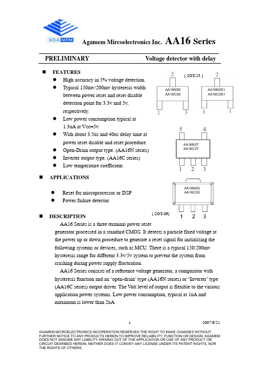
2007/6/21AGAMEM MICROELECTRONICS INCOPERATION RESERVES THE RIGHT TO MAKE CHANGES WITHOUT1___________________________________________________________ PRELIMINARY Voltage detector with delay`APPLICATIONSz Reset for microprocessor or DSP z Power failure detectorDESCRIPTIONAA16 Series is a three terminal power resetgenerator processed in a standard CMOS. It detects a particle fixed voltage at the power up or down procedure to generate a reset signal for initializing the following systems or devices, such as MCU. There is a typical 150/200mv hysteresis range for different 3.3v/5v system to prevent the system from crashing during power supply fluctuation.AA16 Series consists of a reference voltage generator, a comparator with hysteresis function and an ‘open-drain’ type (AA16N series) or ‘Inverter’ type (AA16C series) output driver. The V olt level of output is flexible to the various application power systems. Low power consumption, typical at 1uA and maximum is lower than 2uA.FEATURESz High accuracy in 5% voltage detection. z Typical 150mv/200mv hysteresis widthbetween power reset and reset disable detection point for 3.3v and 5v, respectively.z Low power consumption typical at1.3uA at Vcc=5v.z With about 3.5us and 40us delay time atpower reset disable and reset procedure. z Open-Drain output type. (AA16N series)z Inverter output type. (AA16C series) z Low temperature coefficient. ( SOT-25 )AA16N3G AA16C3GAA16N3T AA16C3TAA16N3S AA16C3SAA16N3S1 AA16C3S1( SOT-23 )( SOT-89)2007/6/21AGAMEM MICROELECTRONICS INCOPERATION RESERVES THE RIGHT TO MAKE CHANGES WITHOUT2___________________________________________________________ PRELIMINARY Voltage detector with delaySOT-23 SOT-89 PIN DESCRIPTIONSymbol Pin-No TypeFunctionV out 1 O Power Reset signal output. It’s an Open –Drain or Inverter outputtype. Its output state level like belowReset : Low ; Reset disable : High ImpedanceVcc 2 Supply Power GND 3Ground SOT-25 PIN DESCRIPTIONSymbol Pin-No TypeFunctionNc 1 O Not Connect Sub 2 substrate GND 3 GroundV out 4 Power Reset signal output. It’s an Open –Drain or Inverter output type. Its output state level like belowReset : Low; Reset disable : High ImpedanceVcc 5 Supply PowerBLOCK DIAGRAM2007/6/21AGAMEM MICROELECTRONICS INCOPERATION RESERVES THE RIGHT TO MAKE CHANGES WITHOUT3Agamem Mircoelectronics Inc. AA16 Series___________________________________________________________ PRELIMINARY Voltage detector with delayELECTRICAL CHARACTERISTICSABSOLUTE MAXIMUM RATINGS (See NOTE) RatingParameter SymbolMINTYPMAXUNIT CONDITIONSupply V olateg Vcc -0.3 7 V Output V olatge V OUT -0.3Vcc+0.3VTa = +25 ; GND = 0V Operating Ambient Temperature Ta -20 70 Storage TemperatureTs -55 125NOTE: Stress above those listed under “Absolute Maximum Rating” may cause the device permanent damage. This is a stress rating only factor and functional operation of the device at these or any other conditions above those indicated in the operational section of this specification is not implied. Exposure to absolute maximum rating conditions for an extending period of time may affect the reliability of the device.RECOMMENDED OPERATING CONDITIONS Ta = 25* Output can’t be described because the system isn’t stable when the supply voltage Vcc is less than 1.5V2007/6/21AGAMEM MICROELECTRONICS INCOPERATION RESERVES THE RIGHT TO MAKE CHANGES WITHOUT4___________________________________________________________ PRELIMINARY Voltage detector with delaySUPPLY CURRENT MEASUREMENT CHART* V out is an ‘Open-Drain’ output type. A resistance between it and Vcc is necessary to pick it up.* V out is an ‘Inverter’ output type. No resistance between it and Vcc.2007/6/21AGAMEM MICROELECTRONICS INCOPERATION RESERVES THE RIGHT TO MAKE CHANGES WITHOUT5___________________________________________________________ PRELIMINARY Voltage detector with delayOUTPUT CHARACTERISTIC TESTING CONDITION* V out is an ‘Open-Drain’ output type. A resistance between it and Vcc isnecessary to pick it up.* V out is an ‘Inverter’ output type. No resistance between it and Vcc.2007/6/21AGAMEM MICROELECTRONICS INCOPERATION RESERVES THE RIGHT TO MAKE CHANGES WITHOUT6___________________________________________________________ PRELIMINARY Voltage detector with delayFig-1 : Reset & Reset Disable Transfer Point* V RSD , reset disable voltage, is the detected output point when Vcc is increasing. V RS , resetvoltage, is the detected output point when Vcc is decreasing. T RSD and T RS is the correspondingdelay time between the V RSD and V RS to the rising edge and falling edge of V out.** After V out is settled, its rising and falling slope should be equal to the slope of Vcc because there is only a resistance between Vcc and V out. The maximum value of V out is equal to the one of Vcc, too.t2007/6/21AGAMEM MICROELECTRONICS INCOPERATION RESERVES THE RIGHT TO MAKE CHANGES WITHOUT7___________________________________________________________ PRELIMINARY Voltage detector with delayFig-2 : Hysteresis Chart* Output can’t be described correctly because the system isn’t stable when the supply voltage Vcc is less than 1.5V** In the Vcc increasing procedure, V out equal to Vcc as Vcc is larger than V RSD . In the Vcc decreasing procedure, V out won’t be change to Vcc until Vcc is smaller than V RS . The width between V RS and V RSD is so called ‘Hysteresis range’V2007/6/21AGAMEM MICROELECTRONICS INCOPERATION RESERVES THE RIGHT TO MAKE CHANGES WITHOUT8___________________________________________________________ PRELIMINARY Voltage detector with delayFig-3 : Output Delay Timing ChartThere existing an output identification range as Vcc is less than 1.5V sounder the testing condition this area should be keep off.2007/6/21AGAMEM MICROELECTRONICS INCOPERATION RESERVES THE RIGHT TO MAKE CHANGES WITHOUT9Agamem Mircoelectronics Inc. AA16 Series___________________________________________________________ PRELIMINARY Voltage detector with delaySOT-23 OUTLINEDRAWINGDIMENSIONS IN MILLIMETERSSYMBOLS MIN NOM MAX A 1.00 1.10 1.30 A1 0.00 - - - 0.10 A2 0.70 0.80 0.90 0.35 0.40 0.50 C 0.10 0.15 0.25D 2.70 2.90 3.10E 1.40 1.60 1.80 - - - 1.90(TYP)- - - H 2.60 2.80 3.000.37 - - - - - - 1 1 5 9NOTES: 1. Package body sizes excludemold flash protrusions orgate burrs 2. Tolerance 0.1000 (4 mil) unless otherwise specified3. Coplanarity:0.10004. Dimension l is measured in gage plane2007/6/21AGAMEM MICROELECTRONICS INCOPERATION RESERVES THE RIGHT TO MAKE CHANGES WITHOUT10Agamem Mircoelectronics Inc. AA16 Series___________________________________________________________ PRELIMINARY Voltage detector with delaySOT-25 OUTLINE DRAWINGDIMENSIONS IN MILLIMETERSSYMBOLS MIN NOM MAX A 1.00 1.10 1.30 A1 0.00 - - - 0.10 A2 0.70 0.80 0.90 0.35 0.40 0.50 C 0.10 0.15 0.25 D 2.70 2.90 3.10 E 1.50 1.60 1.80 - - - 1.90(TYP)- - - H 2.60 2.80 3.00 0.37 - - - - - -1 1 5 9 - - - 0.95(TYP)- - -NOTES:1. Package body sizes excludemold flash protrusions or gate burrs2. Tolerance 0.1000 (4mil) unless otherwise specified3. Coplanarity:0.10004. Dimension l is measured ingage plane2007/6/21AGAMEM MICROELECTRONICS INCOPERATION RESERVES THE RIGHT TO MAKE CHANGES WITHOUT11___________________________________________________________ PRELIMINARY Voltage detector with delaySOT-89 OUTLINE DRAWINGDIMENSIONS INMILLIMETERSDIMENSIONS ININCHESSYMBOLSMIN NOM MAX MINNOM MAX A 1.40 1.50 1.60 0.055 0.059 0.063A1 0.80 1.04 --- 0.031 0.041 --- b 0.36 0.42 0.48 0.014 0.016 0.018b1 0.41 0.47 0.53 0.016 0.018 0.020C 0.38 0.40 0.43 0.014 0.015 0.017D 4.40 4.50 4.60 0.173 0.177 0.181 D1 1.40 1.60 1.75 0.055 0.062 0.069--- --- 4.25 --- --- 0.1672.40 2.50 2.60 0.094 0.098 0.1022.903.00 3.10 0.114 0.118 0.122 0.35 0.40 0.45 0.014 0.016 0.018S 0.65 0.75 0.85 0.026 0.030 0.0341.40 1.50 1.60 0.054 0.059 0.063NOTES:1. Package body sizes excludemold flash protrusions or gate burrs2. Tolerance 0.1000 (4mil) unless otherwise specified3. Coplanarity:0.10004. Dimension l is measured in gage plane2007/6/21AGAMEM MICROELECTRONICS INCOPERATION RESERVES THE RIGHT TO MAKE CHANGES WITHOUT12___________________________________________________________ PRELIMINARY Voltage detector with delayORDERING INFORMATIONNote: For there being two kinds of pin assignment in SOT-23 package, we mark S and S1 to distinguish.S S1AA16 X Y Z1。
1610_print 打印机说明书

4. 使用 TWAIN 扫描仪功能
TWAIN 扫描仪 ........................................................................................... 25 使用 TWAIN 扫描仪的准备步骤 ................................................................. 26
简介
本手册包含关于本设备操作和使用的详细说明和注意事项。为了您的安全和利益,请在使用本设备前仔 细阅读本手册。为了便于参考,请将本手册存放在随手可取之处。
重要事项
本手册的内容若有更改,恕不另行通知。对于因操作和使用本设备而导致的直接、间接、特殊、偶然或 必然损失,本公司概不负责。
切勿复印或打印法律禁止复制的任何项目。 地方法律通常禁止复印或打印下列项目: 钞票、印花税票、债券、股票、银行汇票、支票、护照、驾驶执照。 上述列表仅供参考,未涵盖全部项目。对其完整性或准确性,我们概不负责。如果对于复印或打印某些 项目的合法性有疑问,请与您的法律顾问联系。
DDST Unit Type A / Type B
操作说明书
打印机 / 扫描仪参考
1 准备使用 2 安装软件 3 使用打印机功能 4 使用 TWAIN 扫描仪功能 5 故障排除 6 附录
使用本设备前请仔细阅读本手册,并妥善保存以备今后参考。为了安全正确使用,务必在使用设备之前阅读 “复印参 考”中的 “安全信息”。
提供本设备的概况介绍,并说明系统设置值(纸盘、主要操作员工具等)以及 故障排除方法。 ❖ 复印参考 说明将本设备用作复印机时的操作步骤、功能和故障排除方法。 ❖ 打印机 / 扫描仪参考 (本手册) 说明将本设备用作打印机 / 扫描仪时的系统设置、操作步骤、功能和故障排除 方法。
MIL-STD-202G Method 310(中文版)
MIL-STD-202G METHOD 310 CONTACT-CHATTER MONITORING接點抖動監測1. PURPOSE. This test is conducted for the purpose of detecting contact-chatter in electrical and electronic component parts having movable electrical contacts, such as relays, switches, circuit breakers, etc., where it is required that the contacts do not open or close momentarily, as applicable, for longer than a specified time-duration (see 4.3) under environmental test conditions, such as vibration, shock, or acceleration. This test method provides standard test procedures for monitoring such "opening of closed contacts" or "closing of open contacts".1.目的:這測試執行確定在電器和電子零件部份有作切換電器接觸時的接點抖動目的,如繼電器,開關,電流斷路器,等。
接觸的地方不能有短暫的斷開或導通。
如適用的環境試驗條件下,特定的持續長時間期間(見4.3),如:振動,衝擊或加速。
這檢驗方法提供標準測試程序對於監測如”閉合接點打開”或”打開接點閉合”兩種測試電路。
2. TEST CIRCUITS.2.測試電路2.1 Selection. In this method there are two test-circuits: A (see3.1), and B (see 3.2). The selection of the test-circuit depends largely upon the type of electrical contacts to be tested. Test-circuit B is preferred, whenever possible, to avoid contact contamination caused by the formation of carbonaceous deposits on the contacts. The individual specification shall specify the test-circuit and time-duration (see4.3) required in connection with monitoring of shock and vibration tests. The test-circuits listed herein are "recommended" reference circuits. Any comparable test-circuit which meets the test requirements and the calibration procedures as stated herein , may be used for this test.:A(見3.1),和B(見3.2)。
BAS16L中文资料
MBG704
10
1
10−1 1 Based on square wave currents. Tj = 25 °C prior to surge. 10
102
103
tp (µs)
104
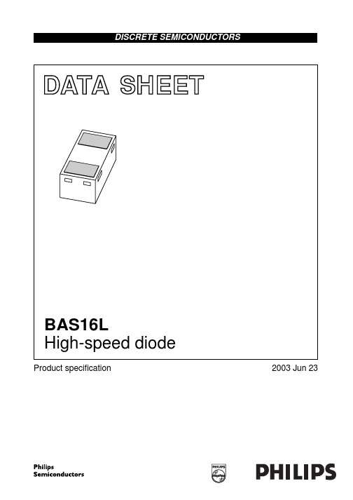
Fig.4 Maximum permissible non-repetitive peak forward current as a function of pulse duration.
2003 Jun 23
2
元器件交易网
Philips Semiconductors
Product specification
High-speed diode
ELECTRICAL CHARACTERISTICS Tamb = 25 °C unless otherwise specified. SYMBOL VF forward voltage PARAMETER CONDITIONS see Fig.3 IF = 1 mA IF = 10 mA IF = 50 mA IF = 150 mA IR reverse current see Fig.5 VR = 25 V VR = 75 V VR = 25 V; Tj = 150 °C VR = 75 V; Tj = 150 °C Cd trr diode capacitance reverse recovery time VR = 0 V; f = 1 MHz; see Fig.6 when switched from IF = 10 mA to IR = 10 mA; RL = 100 Ω; measured at IR = 1 mA; 30 1 30 50 1.5 4 715 855 1 1.25
Product specification
DuraBlue 热熔胶机D4L D10L D16L 用户产品手册
DuraBlue 热熔胶机型号D4L、D10L 和D16L用户产品手册零件74013502007 年2 月发行NORDSON 公司●美国佐治亚州●德卢斯诺信公司欢迎您索取产品信息、产品说明和产品询价。
使用下面的网址可以查询诺信公司的一般信息:.来信请寄:诺信公司Attn:Customer Service11475 Lakefield DriveDuluth, GA 30097注意这是诺信公司的出版物,受版权保护。
版权日期为2006 年。
未经诺信公司书面许可,本文件中的任何部分均不得被影印、复制或译为其它语言。
本刊物中信息如有变更,恕不另行通知。
商标AccuJet, AeroCharge, Apogee, AquaGuard, Asymtek, Automove, Baitgun, Blue Box, CanWorks, Century, CF, Clean Coat, CleanSleeve, CleanSpray, ColorMax, Control Coat, Coolwave, Cross-Cut, Cyclo-Kinetic, Dispensejet, DispenseMate, DuraBlue, Durafiber, Dura-Screen, Durasystem, Easy Coat, Easymove Plus, Ecodry, Econo-Coat, e.dot, EFD, e stylized, ETI, Excel 2000, Fillmaster, FlexiCoat, Flexi-Spray, Flex-O-Coat, Flow Sentry, Fluidmove, FoamMelt, FoamMix, HDLV, Heli-flow, Helix, Horizon, Hot Shot, iControl, iFlow, Isocoil, Isocore, Iso-Flo, iTRAX, Kinetix, Little Squirt, LogiComm, Magnastatic, March, Maverick, MEG, Meltex, Microcoat, Micromark, MicroSet, Millennium, Mini Squirt, Mountaingate, MultiScan, Nordson, OptiMix, Package of Values, Pattern View, PermaFlo, Plasmod, Porous Coat, PowderGrid, Powderware, Printplus, Prism, ProBlue, Prodigy, Pro-Flo, ProLink, Pro-Meter, Pro-Stream, RBX, Rhino, Saturn, Scoreguard, Seal Sentry, Select Charge, Select Coat, Select Cure, Slautterback, Smart-Coat, Solder Plus, Spectrum, Speed-Coat, SureBead, Sure Clean, Sure Coat, Sure-Max, Tracking Plus, TRAK, Trends, Tribomatic, TrueBlue, Ultra, Ultrasaver, UpTime, Vantage, Veritec, VersaBlue, Versa-Coat, Versa-Screen, Versa-Spray, Walcom, Watermark,在未来时间里,它们将是诺信公司的注册商标。
BAS16L, BAS40L 产品说明书

应用• 用于汽车和工业应用的标准开关和肖特基二极管资料来源• 数据表:BAS16L (/ppg?86187);BAS40L (/ppg?86189)• 应用说明:DFN 封装的焊接建议 (/doc?86198)• 如有技术问题,请联系:*************************,***********************,*********************• 材料分类:关于合规性的定义,请参见/doc?99912Available采用超小尺寸 DFN1006-2A 封装的小信号 40 V 肖特基和 100 V 开关二极管,带有可见和可润湿侧翼,适用于商业和汽车应用主要优势• 无引线超小型 DFN1006-2A 封装 (1 mm × 0.6 mm × 0.45 mm),带有可润湿侧翼• 功耗优于 SOT-23• 提供通过 AEC-Q101 认证的版本• 表面贴装器件 (SMD) 塑料封装,带有可见和侧壁电镀/可润湿侧翼• 旨在节省空间并提高热性能• BAS40L 由一个 PN 结保护环保护,防止过电压,例如静电放电• 根据 J-STD-020 标准,湿度敏感度 (MSL) 为 1 级• UL 94 V-0 易燃性等级• 支持汽车系统的自动光学检测 (AOI)• 可通过标准的视觉检测来检查焊接情况;不需要 X 射线• 符合 RoHS 标准,不含卤素,并且是 Vishay 绿色产品BAS16L Vishay SemiconductorsSmall Signal Fast Switching Diode 链接至其他资源机械数据案例:DFN1006-2A 重量:0.83 mg模塑料的易燃性等级: UL 94 V-0端子:保证了高温焊接:最高峰值温度 260 ℃Peak temperature max. 260 °C 包装代码/选项:每 7" 卷 08/10K (8 mm 带子)/doc?99912(1)Square wave, T j= 25 °C prior to surgeAvailable21 年 3 月 30 日修订采用超小尺寸 DFN1006-2A 封装的小信号 40 V 肖特基和 100 V 开关二极管,带有可见和可润湿侧翼,适用于商业和汽车应用特性• 硅外延平面二极管• 快速开关二极管• 无引线超小型 DFN1006-2A 封装 (1 mm × 0.6 mm × 0.45 mm)• 功耗优于 SOT-23• 表面贴装器件 (SMD) 塑料封装,带有可 见和侧壁电镀/可润湿侧翼• 可通过标准的视觉检测来检查焊接情况。
STP16N10L中文资料

STP16N10LN - CHANNEL 100V - 0.14 Ω - 16A - TO-220POWER MOS TRANSISTORs TYPICAL R DS(on) = 0.14 Ωs AVALANCHE RUGGED TECHNOLOGY s 100% AVALANCHE TESTEDs REPETITIVE AVALANCHE DATA AT 100o C s HIGH CURRENT CAPABILITYs 175o C OPERATING TEMPERATURE s HIGH dV/dt RUGGEDNESS sAPPLICATION ORIENTED CHARACTERIZATIONAPPLICATIONS s HIGH CURRENT, HIGH SPEED SWITCHING s POWER MOTOR CONTROL s DC-DC & DC-AC CONVERTERS s SYNCRONOUS RECTIFICATION®INTERNAL SCHEMATIC DIAGRAMABSOLUTE MAXIMUM RATINGSSymbol ParameterValue Unit V DS Drain-source Voltage (V GS = 0)100V V DGR Drain- gate Voltage (R GS = 20 k Ω)100V V GS Gate-source Voltage± 15V I D Drain Current (continuous) at T c = 25 o C 16A I D Drain Current (continuous) at T c = 100 o C 11A I DM (•)Drain Current (pulsed)64A P tot Total Dissipation at T c = 25 o C 90W Derating Factor0.4W/o C dV/dt(1)Peak Diode Recovery voltage slope 0.6V/nsT stg Storage Temperature-65 to 175o C T jMax. Operating Junction Temperature175oC TYPE V DSS R DS(on)ID STP16N10L100 V< 0.16 Ω16 AMarch 1999123TO-2201/5THERMAL DATAR thj-case R thj-amb R thc-sinkT l Thermal Resistance Junction-case MaxThermal Resistance Junction-ambient MaxThermal Resistance Case-sink TypMaximum Lead Temperature For Soldering Purpose1.6762.50.5300o C/Wo C/Wo C/Wo CAVALANCHE CHARACTERISTICSSymbol Parameter Max Value UnitI AR Avalanche Current, Repetitive or Not-Repetitive(pulse width limited by T j max)16AE AS Single Pulse Avalanche Energy(starting T j = 25 o C, I D = I AR, V DD = 50 V)150mJELECTRICAL CHARACTERISTICS (T case = 25 o C unless otherwise specified)OFFSymbol Parameter Test Conditions Min.Typ.Max.Unit V(BR)DSS Drain-sourceBreakdown VoltageI D = 250 µA V GS = 0100VI DSS Zero Gate VoltageDrain Current (V GS = 0)V DS = Max RatingV DS = Max Rating T c = 125 o C110µAµAI GSS Gate-body LeakageCurrent (V DS = 0)V GS = ± 15 V± 100nA ON (∗)Symbol Parameter Test Conditions Min.Typ.Max.Unit V GS(th)Gate Threshold Voltage V DS = V GS I D = 250 µA1 1.7 2.5VR DS(on)Static Drain-source OnResistance V GS = 5V I D = 8 AV GS = 10V I D = 8 A0.140.120.160.14ΩΩI D(on)On State Drain Current V DS > I D(on) x R DS(on)maxV GS = 10 V16A DYNAMICSymbol Parameter Test Conditions Min.Typ.Max.Unitg fs (∗)ForwardTransconductanceV DS > I D(on) x R DS(on)max I D = 8 A 6.510SC iss C oss C rss Input CapacitanceOutput CapacitanceReverse TransferCapacitanceV DS = 25 V f = 1 MHz V GS = 080015050110020070pFpFpFSTP16N10L 2/5ELECTRICAL CHARACTERISTICS (continued)SWITCHING ONSymbol Parameter Test Conditions Min.Typ.Max.Unitt d(on) t r Turn-on TimeRise TimeV DD = 50 V I D = 8 AR G = 4.7 Ω V GS = 5 V15402055nsnsQ g Q gs Q gd Total Gate ChargeGate-Source ChargeGate-Drain ChargeV DD = 80 V I D = 16 A V GS = 5 V2061030nCnCnCSWITCHING OFFSymbol Parameter Test Conditions Min.Typ.Max.Unitt r(Voff) t f t c Off-voltage Rise TimeFall TimeCross-over TimeV DD = 80 V I D = 16 AR G = 4.7 Ω V GS = 5 V121225181835nsnsnsSOURCE DRAIN DIODESymbol Parameter Test Conditions Min.Typ.Max.UnitI SD I SDM(•)Source-drain CurrentSource-drain Current(pulsed)1664AAV SD (∗)Forward On Voltage I SD = 16 A V GS = 0 1.5Vt rr Q rr I RRM Reverse RecoveryTimeReverse RecoveryChargeReverse RecoveryCurrentI SD = 16 A di/dt = 100 A/µsV DD = 30 V T j = 150 o C1455808nsµCA(∗) Pulsed: Pulse duration = 300 µs, duty cycle 1.5 %(•) Pulse width limited by safe operating areaSTP16N10L3/5DIM.mminch MIN.TYP.MAX.MIN.TYP.MAX.A 4.40 4.600.173 0.181C 1.23 1.320.048 0.051D 2.40 2.720.094 0.107D1 1.27 0.050E 0.49 0.700.019 0.027F 0.61 0.880.024 0.034F1 1.14 1.700.044 0.067F2 1.14 1.700.044 0.067G 4.95 5.150.194 0.203G1 2.4 2.70.094 0.106H210.0 10.400.393 0.409L2 16.4 0.645L413.0 14.00.511 0.551L5 2.65 2.950.104 0.116L615.25 15.750.600 0.620L7 6.2 6.60.244 0.260L9 3.5 3.930.137 0.154DIA.3.753.850.1470.151L6ACDED 1FGL7L2Dia.F 1L5L4H 2L9F 2G 1TO-220 MECHANICAL DATAP011CSTP16N10L4/5Information furnished is believed to be accurate and reliable. However, STMicroelectronics assumes no responsibility for the consequences of use of such information nor for any infringement of patents or other rights of third parties which may result from its use. No license is granted by implication or otherwise under any patent or patent rights of STMicroelectronics. Specification mentioned in this publication are subject to change without notice. This publication supersedes and replaces all information previously supplied. STMicroelectronics products are not authorized for use as critical components in life support devices or systems without express written approval of STMicroelectronics.The ST logo is a trademark of STMicroelectronics © 1999 STMicroelectronics – Printed in Italy – All Rights ReservedSTMicroelectronics GROUP OF COMPANIESAustralia - Brazil - Canada - China - France - Germany - Italy - Japan - Korea - Malaysia - Malta - Mexico - Morocco - The Netherlands -Singapore - Spain - Sweden - Switzerland - Taiwan - Thailand - United Kingdom - U.S.A..STP16N10L5/5。
SCM-16用户手册

SCM-16系列通过X0、X1端口可与西门子、爱默生任一款PLC的I0.0、
I0.1相连实现数据上传,数据上传过程不影响客户PLC主程序的正常运行,
同时确保不会改变主程序中寄存器值。接口程序由科思免费提供。
COCIS
SCM-16
POWER RUN ERROR
I1 I2 I3 I4 I5 I6
图1-2 模块接口端子图 打开各盖板后便露出接口和用户端子,如图1-2 所示。 SCM-16系列接线端子的定义见表1-1。
3 特性设置
3.1 模拟输入通道与PLC寄存地址对应表
模拟信号输入
PLC数据存放地址
I1 or V1
VW1002
I2 or V2
VW1004
I3 or V3
VW1006
I4 or V4
VW1008
I5 or V5
VW1010
I6 or V6
VW1012
I7 or V7
VW1014
I8 or V8
VW1016 ★
T1
VW1018 ★
T2
VW1020 ★
T3
VW1022 ★
T4Βιβλιοθήκη VW1024 ★T5
VW1026 ★
T6
VW1028 ★
T7
VW1030 ★
T8
VW1032 ★
★如果电流为7通道,那么温度通道的寄存器地址就相应减 2。
3.2 占用PLC硬件资源
1、输入口:I0.0 ,I0.1
2、数据存储器:18 个
产生电气干扰的电线。 2.如果输入信号有电气噪声或电压波动,可以接一个平滑电容器(0.1
μF~0.47μF/25V)。 3.工作电源建议使用PLC自带输出的24VDC电源。如果使用外部的24VDC
LNSZ16中文资料

FEATURESMultilayer structure allows diverse resistance value in the same B constantMultilayer structure allows lower resistance at high B constant.Solder plating with Ni barrier gives high reliability for both flow and reflow soldering.Unified shape and tightly controlled dimension is fit to high mounting speed.APPLICATIONSTemperature compensation for crystal oscillator (TCXO)Temperature compensation for Personal computer Temperature detection for CPU and memory device Temperature detection for battery packTemperature compensation for contrast of LCDLNS V 16 G 103 J PDESCRIPTIONThe LNS series is manganese oxide based NTC thermistor,which shows non-linear resistance-temperature behavior.Multilayered structure has as high reliability as monoblock type,even without protective glass coating, since the active electrode and sensor layer is buried inside the ceramic body.NTC Thermistor SMDSeries B constantZ 3250K K 3435K Y 3670K W 3890K A 3970K V 4150K U 4550K T 4750KChip size (mm)10 1.0 x 0.5 x 0.5 (inches 0402)16 1.6 x 0.8 x 0.8 (inches 0603)202.0 x 1.2 x 0.8 (inches 0805)Resistance at 25 ¡10110 ¡¿101= 100¥10210 ¡¿102= 1 K ¥10310 ¡¿103= 10 K ¥PackageP Paper taping E Emboss taping BBulkResistance deviation rangeF ¡1£¥H ¡3£¥J ¡5£¥K¡10£¥ORDERING INFORMATIONB constant deviation rangeF ¡1%G ¡2%H¡3%SPECIFICATIONS1005(0402) sizeResistance @ 25o CThe zero-power resistance at the standard temperature of 25o C. The zero-power resistance means the value of DC resistance of a thermistor measured at a specified temperature, with electric load being kept so small that there is no noticeable change in the measured resistance by the influence of the applied electric load.Bconstant 25 / 85B = ln(R0/R1) / (1/T- 1/T1) Without special note, B constant is calculated from the resistance values at 25o C and 85o C[B25/85], which is the most common.Dissipation constant (¥‰)Dissipation factor is defined as the ratio at a specified ambient temperature of a change in power dissipation in a thermistor to the resultant body temperature change.¡⁄¥= P/( T1- 25o C) mW/ o C¡⁄P : dissipated power¡⁄T1 : thermistor temp, 85¡0.1o CMaximum power rating PThis is the maximum handling power, keeping its temperature not exceeding the allowed maximum temperature for operation.¡⁄P max = ¥(T max- T a)¡⁄¥:dissipation constant¡⁄T a:25o C¡⁄T max:125o CThermal Time ConstantThe time necessary for an unloaded thermistor to vary its temperature by 63.2%of the difference between its initial and final temperatures. Initial temperature is 85¡0.1o C and final1608(0603) sizeResistance @ 25o CThe zero-power resistance at the standard temperature of 25o C. The zero-power resistance means the value of DC resistance of a thermistor measured at a specified temperature, with electric load being kept so small that there is no noticeable change in the measured resistance by the influence of the applied electric load.Bconstant 25 / 85B = ln(R0/R1) / (1/T- 1/T1) Without special note, B constant is calculated from the resistance values at 25o C and 85o C[B25/85], which is the most common.Dissipation constant (¥‰)Dissipation factor is defined as the ratio at a specified ambient temperature of a change in power dissipation in a thermistor to the resultant body temperature change.¡⁄¥= P/( T1- 25o C) mW/ o C¡⁄P : dissipated power¡⁄T1 : thermistor temp, 85¡0.1o CMaximum power rating PThis is the maximum handling power, keeping its temperature not exceeding the allowed maximum temperature for operation.¡⁄P max = ¥(T max- T a)¡⁄¥:dissipation constant¡⁄T a:25o C¡⁄T max:125o CThermal Time ConstantThe time necessary for an unloaded thermistor to vary its temperature by 63.2%of the difference between its initial and final temperatures. Initial temperature is 85¡0.1o C and final temperature is 47.1¡0.1o C.Resistance @ 25o CThe zero-power resistance at the standard temperature of 25o C . The zero-power resistance means the value of DC resistance of a thermistor measured at a specified temperature,with electric load being kept so small that there is no noticeable change in the measured resistance by the influence of the applied electric load.Bconstant 25 / 85B = ln(R 0/R 1) / (1/T 0- 1/T 1) Without special note, B constant is calculated from the resistance values at 25oC and 85o C [B25/85], which is the most common.Dissipation constant (¥‰)Dissipation factor is defined as the ratio at a specified ambient temperature of a change in power dissipation in a thermistor to the resultant body temperature change. ¡⁄¥= P/( T 1- 25o C ) mW/ o C ¡⁄P : dissipated power ¡⁄T1 : thermistor temp, 85¡0.1o C Maximum power rating PThis is the maximum handling power, keeping its temperature not exceeding the allowed maximum temperature for operation. ¡⁄P max = ¥(T max - T a )¡⁄¥:dissipation constant ¡⁄T a :25o C ¡⁄T max :125o C Thermal Time ConstantThe time necessary for an unloaded thermistor to vary its temperature by 63.2%of the difference between its initial and final temperatures. Initial temperature is 85¡0.1o C and final temperature is 47.1¡0.1o C .2012(0805) sizeRESISTANCE VS. TEMPERATURE TABLERELIABILITY TEST METHODStructure and Dimension CHIP STRUCTURECHIP DIMENSIONSize A B C D E F G H Jtnote 1608 1.0¡0.1 1.9¡0.18.0¡0.1 3.5¡0.05 1.75¡0.1 4.0¡0.1 2.0¡0.05 4.0¡0.1 1.5+0.1-0.00.23¡0.02paper 10050.62¡0.04 1.12¡0.048.0¡0.1 3.5¡0.05 1.75¡0.1 4.0¡0.1 2.0¡0.05 4.0¡0.1 1.5+0.1-0.00.6¡0.05paperTape and Reel Packaging for Paper PackageStructure of TapingTaping must have leader and empty component compartment as shown in the following figure.Size A B W F E P1P2P0D0t1t2note 3216 1.73¡0.1 3.56¡0.18.0+0.3-0.1 3.5¡0.05 1.75¡0.1 4.0¡0.1 2.0¡0.05 4.0¡0.1 1.5+0.1-0.00.23¡0.02 1.14¡0.1emboss 2012 1.45¡0.1 2.25¡0.18.0+0.3-0.1 3.5¡0.05 1.75¡0.1 4.0¡0.1 2.0¡0.05 4.0¡0.1 1.5+0.1-0.00.23¡0.02 1.0¡0.1embossTape and Reel Packaging for Emboss PackagePackage Quantity12,000(pcs/Reel) - 1005 size4,000(pcs/Reel) - 1608, 2012, 3216 sizePackagingRecommended Land PatternSolderingHand soldering : 280o C max., 5sec max.Reflow profileComponent LayoutLocate the product horizontal to the direction at which bending is applied.Component MountingSMT Process CharacteristicsSolder and FluxSolder : Eutetic solder recommended Flux : Rosin based flux recommendedHalogen content 0.2 w% or less recommendedFlow profile。
DASEN 16i规格说明书

带小数点可变段,字节地址格式
计算器型/最小输入单位型
备注
用系统参数可以 任意设定,但是 与位置检测器精 度有关
3.1.3. 插补
NO
名称
1 定位
2 直线插补
3 圆弧插补
规
格
使用G00指令,快移进行定位。
使用G00指令,进行直线插补。
使用G02/G03指令,进行圆弧插补。
备注
3
针对指令进给速度,0~200%(每10%)的倍率 改变。
针对快移,手动进给进行直线形的加减速。
针对快移进行S字型的加减速。
用G00快移向行程范围外移动时,移动到行程 界限,再次返回到行程范围内的停留功能。
需设定系统参数
4
3.1.5. 程序记忆.编辑
NO
名称
1 程序记忆容量
2 程序编辑
3 程序名
4 序号 5 序号检索 6 程序列表
DASEN - 16 M
规格书
警告 请在产品使用前一定要阅读说明书
本书请进行保管不要丢失 二○○七年
大连大森数控技术发展中心有限公司
目 录
1 概要
2
2 特征
2
3 规格一览
3
3.1 基本规格
3
3.1.1 控制轴
3
3.1.2 输入指令
3
3.1.3 插补
3
3.1.4 进给
4
3.1.5 程序记忆.编辑
用G92指令,设定把轴现在位置变为指令坐标值 的坐标系。
用G53/G57指令,最大5轴工件坐标预置 组数:9组(H901~H909)
用G54/G55/G56指令,最大12轴工件坐标预置
要设定系统 参数用G21指令自动返回第 Nhomakorabea~4参考点
美国DT作业安全设备有限公司的Model STDL-10 温度数据记录器说明说明书

Submerata
Logger
High/Low Alarm Setting, Continuous Recording, Compact
1/8˝ JACK FOR USB CABLE
GASKET
2-19/64 [58.42]
USER REPLACEABLE BATTERY SIZE 1/2AA
413
Power Requirements: User replaceable, 3.6V lithium battery. Battery Life: 1 year (approx). Alarms: Programmable high/low. Interface: USB port (interface cable required). Housing Material: 316L stainless steel (food grade). Weight: 1.8 oz (51 g). Agency Approvals: CE.
GASKET
REMOVABLE CAP
5/8 [15.88]
23/32 [18.42]
REMOVABLE CAP
The Model STDL-10 is a miniature data logger that accurately records temperatures from -40 to 176°F (-40 to 80°C). The submersible, compact data logger features programmable high and low alarms that are indicated with green and red LEDs. Standing only 2.6 in (66 mm) tall and 0.7 in (18 mm) in diameter, it can record over 32,000 measurements. The easy to use DL700 software makes retrieving data simple and allows for user selectable sampling rates. The STDL-10 can easily be started and stopped from a PC or delayed to start up to six months in advance.
多串泰斯操作说明书

描述
最低一节电池的正极 第 2 节电池的正极 第 3 节电池的正极 第 4 节电池的正极 第 5 节电池的正极 第 6 节电池的正极 第 7 节电池的正极 第 8 节电池的正极 第 9 节电池的正极 第 10 节电池的正极 预留,未定义 暂定,实际未连接 暂定,实际未连接 暂定,实际未连接 暂定,实际未连接 用来测试正极内阻,必须用独立的引线连接到保护板的 B+端 独立的正极充电端口,连接到保护板的 C+端(如果有的话) 用来测试正极内阻,必须用独立的引线连接到保护板的 P+端 第 11 节电池的正极 第 12 节电池的正极 第 13 节电池的正极 第 14 节电池的正极 第 15 节电池的正极 第 16 节电池的正极 第 17 节电池的正极 第 18 节电池的正极 第 19 节电池的正极 第 20 节电池的正极 最下面一节电池的负极,必须用单独的导线连接到 B暂定,实际未连接 暂定,实际未连接 暂定,实际未连接 暂定,实际未连接 用来测试负极内阻,必须用独立的引线连接到保护板的 B-端 独立的负极充电端口,连接到保护板的 C-端(如果有的话) 用来测试负极内阻,必须用独立的引线连接到保护板的 P-端
4. 开机使用
本测试仪可以单独使用,也可以通过 USB 接口连接电脑使用,通过电脑连接,可以更方便的设 置保护板参数,记录保护板测试结果数据,导出测试结果表格,保存保护板设置参数文件等等,特 别推荐客户采用电脑连接的方式使用该测试仪。
将电源线插入仪器背后的电源插座,开启面板上的电源开关,测试仪将显示如下画面:
按任意键,测试仪将进入测试功能选择界面,如下所示:
从上向下,从左至右分别是: 1, 生产测试:可以按照生产参数设置的基本模式测试保护板的常规参数,该测试模式常用于
SinOne SCT80S16B 10V CS 8 通道触控按键专用 IC 说明书

SCT80S16B SinOne10V CS 8通道触控按键专用IC 目录目录 (1)1 总体描述 (3)2 主要功能和优势 (3)2.1 功能 (3)2.2 优势 (3)3 管脚定义 (3)3.1 管脚配置 (3)3.2 管脚定义 (4)4 电气性能 (4)4.1 推荐工作条件 (4)4.2 直流电气特性 (4)5 封装信息 (5)6 应用设计指南 (6)6.1 未使用通道处理 (6)6.2 邻键距离 (6)6.3 通讯输出选择 (6)6.3.1 通讯输出选择OUTS (6)6.3.2 灵敏度设置和键值读取格式 (6)7 注意事项 (9)7.1 典型应用电路 (9)7.2 电路Check List (9)7.3 电源要求 (9)7.4 PCB布局 (9)7.5 PCB布线 (10)7.6 PCB参考图 (10)Page 1 of 11 V 1.17.7 触控面板材料选择 (10)8 规格更改记录 (11)1 总体描述SCT80S16B 是一颗有8个触控通道,带UART/IIC 通讯接口的触控专用IC ,用户可通过UART/IIC 通讯来设置灵敏度。
此IC 具有工业级规格,拥有4KV EFT 和6KV 接触ESD 能力,可顺利通过3V 动态和10V 静态CS 测试,是用户高性能触控按键方案的首选。
非常适合应用于大小家电、安防、工控等应用场合。
2 主要功能和优势2.1 功能● 工作电压:3.3V ~ 5.5V ● 工作温度:-40 ~ 85℃● 触控按键通道:8通道,最多支持两个按键同时被按下 ● 触控按键输出通讯协议:UART/IIC 输出 ● 灵敏度调节:UART/IIC 通讯调节● 上电2s 内可通过UART/IIC 通讯来设置触控通道灵敏度等级 ● 覆盖物厚度:0 ~ 10mm● 有效触摸反应时间:小于100ms ● 允许按键长按时间为10S ●封装:SOP162.2 优势● 发明专利,业界独创; ● 完美触控按键操作体验; ● 用户根据需要设置灵敏度;●超强抗干扰能力,4KV EFT 、6KV ESD 、10V CS 。
fanuc 16i参数说明书
B-63690EN/01
Ȧ No part of this manual may be reproduced in any form. Ȧ All specifications and designs are subject to change without notice.
B–63690EN/01
PREFACE
PREFACE
This manual describes the specialized parameters for the following model:
Product name
Abbreviation
FANUC Series 16i–PB FANUC Series 18i–PB FANUC Series 160i–PB FANUC Series 180i–PB
0: Standard address (X004). When this is selected, the maximum stop time, from when the punching complete signal is input until movement along an axis starts, is 7 msec.
FANUC Series 16i/18i/160i/180i–PB PARAMETER MANUAL
FANUC Series 0i/16/18/20/21 PROGRAMMING MANUAL (Macro Compiler/Macro Executor)
Specification number
B–63682EN B–63523EN B–63523EN–1 B–63683EN B–63684EN B–63525EN B–63530EN
ina310中文规格书

ina310中文规格书英文回答:Texas Instruments INA310。
Key Features.Dual-channel, high-side current and power monitor.Bidirectional current measurement with programmable calibration.Voltage measurement with programmable gain.Internal 12-bit ADC.I² C and SMBus compatible interface.Low power consumption: 350 µA (typical)。
Applications.Current monitoring in battery-powered systems. Power supply monitoring.Load monitoring.Industrial control.Automotive electronics.Technical Specifications.Current Measurement.Measurement range: ±26 A.Accuracy: ±1.5% (typical)。
Programmable calibration.Voltage Measurement.Measurement range: 0 V to 26 V.Programmable gain.Accuracy: ±0.5% (typical)。
ADC.Resolution: 12 bits.Conversion time: 400 µs (typical)。
Interface.I² C and SMBus compatible.Address: 0x40 (default)。
施耐德 LXM16DU15M2X 运动伺服驱动器 Easy Lexium 16 数据表
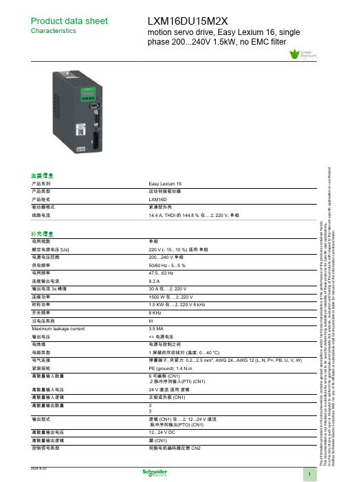
Product data sheetCharacteristicsLXM16DU15M2Xmotion servo drive, Easy Lexium 16, single phase 200...240V 1.5kW, no EMC filter主要信息产品系列Easy Lexium 16产品类型运动伺服驱动器产品短名LXM16D 驱动器格式紧凑型外壳线路电流14.4 A, THDI 的 144.8 % 在…上 220 V, 单相补充信息电网相数单相额定电源电压 [Us]220 V (- 15...10 %) 适用 单相电源电压范围200…240 V 单相供电频率50/60 Hz - 5...5 %电网频率47.5...63 Hz 连续输出电流8.3 A输出电流 3s 峰值30 A 在…上 220 V 连续功率1500 W 在…上 220 V 标称功率 1.5 KW 在…上 220 V 8 kHz 开关频率8 KHz 过电压类别III Maximum leakage current 3.5 MA 输出电压<= 电源电压电绝缘电源与控制之间电缆类型 1 屏蔽的双绞线对 (温度: 0…40 °C)电气连接弹簧端子, 夹紧力: 0.2...2.5 mm², AWG 24...AWG 12 (L, N, P+, PB, U, V, W)紧固扭矩PE (ground): 1.4 N.m 离散量输入数量 6 可编程 (CN1)2 脉冲序列输入(PTI) (CN1)离散量输入电压24 V 直流 适用 逻辑离散量输入逻辑正极或负极 (CN1)离散量输出数量33输出型式逻辑 (CN1) 在…上 12...24 V 直流 脉冲序列输出(PTO) (CN1)离散量输出电压12...24 V DC 离散量输出逻辑漏 (CN1)控制信号类型伺服电机编码器反馈 CN2T h e i n f o r m a t i o n p r o v i d e d i n t h i s d o c u m e n t a t i o n c o n t a i n s g e n e r a l d e s c r i p t i o n s a n d /o r t e c h n i c a l c h a r a c t e r i s t i c s o f t h e p e r f o r m a n c e o f t h e p r o d u c t s c o n t a i n e d h e r e i n .T h i s d o c u m e n t a t i o n i s n o t i n t e n d e d a s a s u b s t i t u t e f o r a n d i s n o t t o b e u s e d f o r d e t e r m i n i n g s u i t a b i l i t y o r r e l i a b i l i t y o f t h e s e p r o d u c t s f o r s p e c i f i c u s e r a p p l i c a t i o n s .I t i s t h e d u t y o f a n y s u c h u s e r o r i n t e g r a t o r t o p e r f o r m t h e a p p r o p r i a t e a n d c o m p l e t e r i s k a n a l y s i s , e v a l u a t i o n a n d t e s t i n g o f t h e p r o d u c t s w i t h r e s p e c t t o t h e r e l e v a n t s p e c i f i c a p p l i c a t i o n o r u s e t h e r e o f .N e i t h e r S c h n e i d e r E l e c t r i c I n d u s t r i e s S A S n o r a n y o f i t s a f f i l i a t e s o r s u b s i d i a r i e s s h a l l b e r e s p o n s i b l e o r l i a b l e f o r m i s u s e o f t h e i n f o r m a t i o n c o n t a i n e d h e r e i n .保护类型防止电压反接: 输入 信号防止短路输出信号: 输出信号防止电压反接: 输出信号过流保护: motor and driver过电压: 驱动欠电压: 驱动过热: 驱动过载: motor and driver超速: 马达物理接口Mini-B USB 适用 Modbus 串行线 从LED状态LED (红色) 充电信号传输功能伺服状态和故障代码 5 7-段显示单元标识CE冷却方式风扇操作位置垂直适用范围伺服电机 BCH16 (130 mm, 1 电机堆栈)宽度65 Mm高度150 Mm深度185.2 Mm净重 1.5 Kg环境EMC 滤波器无EMC 滤波器电磁兼容性传导辐射 - test level: 级别 3 C3类 conforming to IEC 61800-3符合标准IEC 61800-5-1产品认证CEIP 等级IP20抗振动3M4 振幅 = 3 mm (f = 9…200 Hz) 符合 IEC 60721-3-3抗冲击10 gn, 类型 I 符合 IEC 60721-3-3相对湿度5…95 % 无凝结环境温度0…40 °C (无降容)40…55 °C (有)贮存环境温度-40…70 °C工作海拔<= 1000 m 无降容> 1000, < 2000 随着电流降额包装单位Unit Type of Package 1PCENumber of Units in Package 11Package 1 Height20.5 CmPackage 1 Width24 CmPackage 1 Length11 CmPackage 1 Weight 1.6 KgUnit Type of Package 2S04Number of Units in Package 27Package 2 Height30 CmPackage 2 Width40 CmPackage 2 Length60 CmPackage 2 Weight11.96 Kg可持续性产品类型Green Premium 产品REACh法规REACh 声明欧盟ROHS指令主动合规性(超出欧盟 RoHS 法定范围的产品)无汞是中国 ROHS 管理办法中国 ROHS 声明RoHS 豁免信息是环境披露产品环境文件流通资料产品使用寿命终期信息WEEE该产品必须经特定废物回收处理后弃置于欧盟市场,绝不可丢弃于垃圾桶中。
FANUC 16i 160i 18i 180i Series 系统B-63670EN_02 16I 160I单独参数说明书
s-1
B-63670EN/02
PREFACE
ห้องสมุดไป่ตู้PREFACE
Applicable Models
The models covered by this manual, and their abbreviations are :
B-63670EN/02
DEFINITION OF WARNING, CAUTION, AND NOTE
DEFINITION OF WARNING, CAUTION, AND NOTE
This manual includes safety precautions for protecting the user and preventing damage to the machine. Precautions are classified into Warning and Caution according to their bearing on safety. Also, supplementary information is described as a Note. Read the Warning, Caution, and Note thoroughly before attempting to use the machine.
Product Name FANUC Series 16i-LB FANUC Series 160i-LB Abbreviations Series 16i-LB Series 160i-LB 16i-LB 160i-LB
NOTE 1 This manual describes the parameters that are used by the Series 16i/160i-LB only. For parameters common to other models, refer to "Series 16i/18i/160i/180i/160is/180is-MODEL B Parameter Manual" (B-63530EN). 2 Some functions described in this manual may not be applied to some products. For details, refer to the DESCRIPTIONS (B-63662EN).
FANUC 16i 系统参数
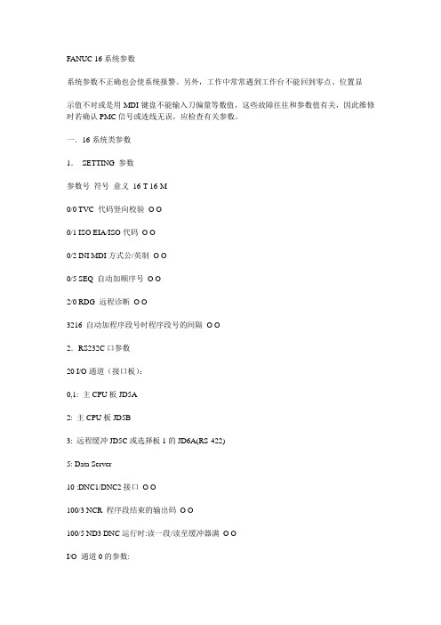
FANUC 16系统参数系统参数不正确也会使系统报警。
另外,工作中常常遇到工作台不能回到零点、位置显示值不对或是用MDI键盘不能输入刀偏量等数值,这些故障往往和参数值有关,因此维修时若确认PMC信号或连线无误,应检查有关参数。
一.16系统类参数1.SETTING 参数参数号符号意义16-T 16-M0/0 TVC 代码竖向校验O O0/1 ISO EIA/ISO代码O O0/2 INI MDI方式公/英制O O0/5 SEQ 自动加顺序号O O2/0 RDG 远程诊断O O3216 自动加程序段号时程序段号的间隔O O2.RS232C口参数20 I/O通道(接口板):0,1: 主CPU板JD5A2: 主CPU板JD5B3: 远程缓冲JD5C或选择板1的JD6A(RS-422)5: Data Server10 :DNC1/DNC2接口O O100/3 NCR 程序段结束的输出码O O100/5 ND3 DNC运行时:读一段/读至缓冲器满O OI/O 通道0的参数:101/0 SB2 停止位数O O101/3 ASII 数据输入代码:ASCII或EIA/ISO O O 101/7 NFD 数据输出时数据后的同步孔的输出O O 102 输入输出设备号:0:普通RS-232口设备(用DC1-DC4码)3:Handy File(3″软盘驱动器)O O103 波特率:10:480011:960012:19200 O OI/O 通道1的参数:111/0 SB2 停止位数O O111/3 ASI 数据输入代码:ASCII或EIA/ISO O O 111/7 NFD 数据输出时数据后的同步孔的输出O O 112 输入输出设备号:0:普通RS-232口设备(用DC1-DC4码)3:Handy File(3″软盘驱动器)O O113 波特率:10:480011:960012:19200 O O其它通道参数请见参数说明书。
第二讲:Lattice公司的isp1016芯片

3) 输入输入单元IOC〔Input Output Cell〕 输入输入单元IOC是功用框图最外层的小方
块,共32个〔IN0 ~ IN31〕。该单元有输入、输 入和双向I/O三类组态。可经过对控制输入输入 三态缓冲器的使能端编程来选择。
检查ispLSI 1016功用框图
4) 输入布线区ORP〔Output Routing Pool〕
• 例如:将外加主时钟由Y0送入作为全局时钟CLK0,此 全局时钟经过时钟公用GLB〔B0〕分频后送至CLK1、 CLK2、IOCLK0、IOCLK1,那么其它GLB或I/O单元可以 任务在较低的频率上。
检查ispLSI 1016功用框图
6) 大块结构〔Megablock〕
• ispLSI 1016 采用了一种分块结构,每8个 GLB连同对应的ORP、IOC等构成一个大块。 此 外,每个大块中还包括2个公用输入端,仅供本 大块内的GLB运用,靠软件自动分配。 • ispLSI 1时钟分配网络CDN〔Clock Distribution Network〕
• CDN的输入信号由三个公用输入端Y0、Y1、Y2提供;
• CDN的输入有五个,其中CLK0、CLK1、CLK2提供应 GLB,IOCLK0和IOCLK1提供应I/O单元;
• 时钟公用GLB〔B0〕的四个输入送至CDN,以树立用 户定义的外部时钟电路。
第二讲:Lattice公司的 isp1016芯片
2021年7月25日星期日
一、ispLSI 1016的结构和特点
ispLSI 1016是ispLSI 1000系列中容量最小的 器件,具有5V的在系统编程才干。
1. ispLSI 1016的主要特点:
集成密度为2000等效门;
是电擦写CMOS〔EECMOS〕器件;
- 1、下载文档前请自行甄别文档内容的完整性,平台不提供额外的编辑、内容补充、找答案等附加服务。
- 2、"仅部分预览"的文档,不可在线预览部分如存在完整性等问题,可反馈申请退款(可完整预览的文档不适用该条件!)。
- 3、如文档侵犯您的权益,请联系客服反馈,我们会尽快为您处理(人工客服工作时间:9:00-18:30)。
STD16NE10LN -CHANNEL 100V -0.07Ω-16A DPAKSTripFET ™POWER MOSFETPRELIMINARY DATAs TYPICAL R DS(on)=0.07Ωs AVALANCHE RUGGED TECHNOLOGY s LOW GATE CHARGEs HIGH CURRENT CAPABILITYs 175o C OPERATING TEMPERATURE s LOW THRESHOLD DRIVEsADD SUFFIX ”T4”FOR ORDERING IN TAPE &REELDESCRIPTIONThis Power MOSFET is the latest development of STMicroelectronics unique ”Single Feature Size ™”strip-based process.The resulting transi-stor shows extremely high packing density for low on-resistance,rugged avalanche characteristics and less critical alignment steps therefore a re-markable manufacturing reproducibility.APPLICATIONSs HIGH CURRENT,HIGH SPEED SWITCHING s SOLENOID AND RELAY DRIVERS s DC-DC &DC-AC CONVERTERS s AUTOMOTIVE ENVIRONMENT®INTERNAL SCHEMATIC DIAGRAMMay 2000ABSOLUTE MAXIMUM RATINGSSymbol ParameterValue Unit V DS Drain-source Voltage (V GS =0)100V V DGR Drain-gate Voltage (R GS =20k Ω)100V V GS Gate-source Voltage±20V I D Drain Current (continuous)at T c =25o C 16A I D Drain Current (continuous)at T c =100o C 11A I DM (•)Drain Current (pulsed)64A P totTotal Dissipation at T c =25oC 55W Derating Factor0.36W/o C dv/dt (1)Peak Diode Recovery voltage slope 7V/nsT st g Storage Temperature-65to 175o C T jMax.Operating Junction Temperature175oC(•)Pulse width limited by safe operating area(1)I SD ≤16A,di/dt ≤300A/µs,V DD ≤V (BR)DSS ,Tj ≤T JMAXTYPE V DSS R DS(o n)I D STD16NE10L100V<0.10Ω16A13DPAK TO-252(Suffix ”T4”)1/6THERMAL DATAR th j-pc b R thj-amb R t hj-s inkT l Thermal Resistance Junction-PC Board MaxThermal Resistance Junction-ambient MaxThermal Resistance Case-sink TypMaximum Lead Temperature For Soldering Purpose2.731001.5275o C/Wo C/Wo C/Wo CAVALANCHE CHARACTERISTICSSymbol Parameter Max Value UnitI AR Avalanche Current,Repetitive or Not-Repetitive(pulse width limited by T j max)16AE AS Single Pulse Avalanche Energy(starting T j=25o C,I D=I AR,V DD=30V)75mJELECTRICAL CHARACTERISTICS(T case=25o C unless otherwise specified)OFFSymbol Parameter Test Conditions Min.Typ.Max.Unit V(BR)DSS Drain-sourceBreakdown VoltageI D=250µA V GS=0100VI DSS Zero Gate VoltageDrain Current(V GS=0)V DS=Max RatingV DS=Max Rating T c=125o C110µAµAI GSS Gate-body LeakageCurrent(V DS=0)V GS=±20V±100nA ON(∗)Symbol Parameter Test Conditions Min.Typ.Max.Unit V GS(th)Gate Threshold Voltage V DS=V GS I D=250µA1 1.7 2.5VR DS(on)Static Drain-source OnResistance V GS=10V I D=8AV GS=5V I D=8A0.070.0850.0850.1ΩΩI D(o n)On State Drain Current V DS>I D(o n)x R DS(on)ma xV GS=10V16A DYNAMICSymbol Parameter Test Conditions Min.Typ.Max.Unitg f s(∗)ForwardTransconductanceV DS>I D(o n)x R DS(on)ma x I D=8A59SC iss C os s C rss Input CapacitanceOutput CapacitanceReverse TransferCapacitanceV DS=25V f=1MHz V GS=0V175016545pFpFpFSTD16NE10L 2/6ELECTRICAL CHARACTERISTICS(continued)SWITCHING ONSymbol Parameter Test Conditions Min.Typ.Max.Unitt d(on) t r Turn-on Delay TimeRise TimeV DD=50V I D=8AR G=4.7 ΩV GS=4.5V(Resistive Load,see fig.3)4080nsnsQ g Q gs Q gd Total Gate ChargeGate-Source ChargeGate-Drain ChargeV DD=80V I D=16A V GS=5V245.51132nCnCnCSWITCHING OFFSymbol Parameter Test Conditions Min.Typ.Max.Unitt d(of f) t f Turn-off Delay TimeFall TimeV DD=50V I D=8AR G=4.7 ΩV GS=4.5V(Resistive Load,see fig.3)4512nsnst r(Voff) t f t c Off-voltage Rise TimeFall TimeCross-over TimeV DD=80V I D=16AR G=4.7 ΩV GS=4.5V(Inductive Load,see fig.5)121735nsnsnsSOURCE DRAIN DIODESymbol Parameter Test Conditions Min.Typ.Max.UnitI SD I SDM(•)Source-drain CurrentSource-drain Current(pulsed)1664AAV SD(∗)Forward On Voltage I SD=16A V GS=0 1.5Vt rr Q rr I RRM Reverse RecoveryTimeReverse RecoveryChargeReverse RecoveryCurrentI SD=16A di/dt=100A/µsV DD=40V T j=150o C(see test circuit,fig.5)1003006nsnCA(∗)Pulsed:Pulse duration=300µs,duty cycle1.5%(•)Pulse width limited by safe operating areaSTD16NE10L3/6Fig.1:Unclamped Inductive Load Test Circuit Fig.3:Switching Times Test Circuits For Resistive Load Fig.2:Unclamped Inductive Waveform Fig.4:Gate Charge test CircuitFig.5:Test Circuit For Inductive Load Switching And Diode Recovery TimesSTD16NE10L4/6DIM.mminch MIN.TYP.MAX.MIN.TYP.MAX.A 2.2 2.40.0860.094A10.9 1.10.0350.043A20.030.230.0010.009B 0.640.90.0250.035B2 5.2 5.40.2040.212C 0.450.60.0170.023C20.480.60.0190.023D 6 6.20.2360.244E 6.4 6.60.2520.260G 4.4 4.60.1730.181H 9.3510.10.3680.397L20.80.031L40.610.0230.039==DL2L413==BE==B 2G2AC 2CHA 1DETAIL ”A”A 2DETAIL ”A”TO-252(DPAK)MECHANICAL DATA0068772-BSTD16NE10L5/6STD16NE10LInformation furnished is believed to be accurate and reliable.However,STMicroelectronics assumes no responsibility for the consequence s of use of such information nor for any infringement of patents or other rights of third parties which may result from its use.No license is granted by implication or otherwise under any patent or patent rights of STMicroelectronics.Specification mentioned in this publication are subject to change without notice.This publication supersedes and replaces all information previously supplied.STMicroelectronics products are not authorized for use as critical components in life support devices or systems without express written approval of STMicroelectronics.The ST logo is a trademark of STMicroelectronics©2000STMicroelectronics–Printed in Italy–All Rights ReservedSTMicroelectronics GROUP OF COMPANIESAustralia-Brazil-China-Finland-France-Germany-Hong Kong-India-Italy-Japan-Malaysia-Malta-Morocco-Singapore-Spain-Sweden-Switzerland-United Kingdom-U.S.A.6/6。
