APMT1135刀片问题说明
Fasttrack磨刀器说明书

2ys.ohuarrptoeonlinlogo. ks
like
either of 3.
the
above
you
are
ready
to
sharpen.
Proceed
to
3. Should your blade make contact at the top or middle of the bevel or be very
n Mark and drill a line of pilot holes through the board
approximately 25mm in from the edge. Row of Fixing
n Screw and glue (if necessary) the
Screws
batten tight up against the board - wipe away the exces1s.glue.
The board can be any reasonable size providing the 4 x rubber feet of the base sit comfortably on it.
n Position the batten along the front of the vice facing edge.
1.1.
2. 2.
3.3.
SET-UP The back of the tool (the un-bevelled side) must be ground absolutely flat before sharpening. This process is imperative if a razor sharp finish is to be acher feet x4 C. Carriage x1 D. Carriage poppers x2 E. Diamond preparation stone 220 grit (black) x1 F. Diamond finishing stone 450 grit (white) x1 G. Cleaning block x1 H. Mounting screw No.8 x 1-1 / 4 ” x1
美国机器与工具公司产品维修部件手册说明书
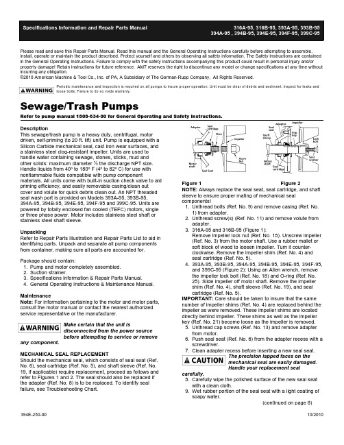
394E-250-0010/2010Please read and save this Repair Parts Manual. Read this manual and the General Operating Instructions carefully before attempting to assemble,install, operate or maintain the product described. Protect yourself and others by observing all safety information. The Safety Instructions are contained in the General Operating Instructions. Failure to comply with the safety instructions accompanying this product could result in personal injury and/or property damage! Retain instructions for future reference . AMT reserves the right to discontinue any model or change specifications at any time without incurring any obligation.©2010 American Machine & Tool Co., Inc. of PA, A Subsidiary of The Gorman-Rupp Company, All Rights Reserved.Periodic m aintenance and inspection is required on all pum ps to insure proper operation. Unit m ust be clear of debris and sedim ent. Inspect for leaks and loose bolts. Failure to do so voids warranty.Sewage/Trash PumpsRefer to pump manual 1808-634-00 for General Operating and Safety Instructions.DescriptionThis sewage/trash pump is a heavy duty, centrifugal, motor driven, self-priming (to 20 ft. lift) unit. Pump is equipped with a Silicon Carbide mechanical seal, cast iron wear surfaces, and a stainless steel clog-resistant impeller. Units are used to handle water containing sewage, stones, sticks, mud and other solids: maximum diameter ½ the discharge NPT size.Handle liquids from 40º to 180º F (4º to 82º C) for use with nonflammable fluids compatible with pump componentmaterials. All units come with built-in suction check valve to aid priming efficiency, and easily removable casing/clean out cover and volute for quick debris clean out. An NPT threaded seal wash port is provided on Models 393A-95, 393B-95,394A-95, 394B-95, 394E-95, 394F-95 and 399C-95. Units are powered by totally enclosed fan cooled (TEFC) motors, single or three phase power. Motor includes stainless steel shaft or stainless steel shaft sleeve.UnpackingRefer to Repair Parts Illustration and Repair Parts List to aid in identifying parts. Unpack and separate all pump components from container, making sure all parts are accounted for. Package should contain:1.Pump and motor completely assembled.2.Suction strainer.3.Specifications Information & Repair Parts Manual.4.General Operating Instructions & Maintenance Manual.MaintenanceNote: For information pertaining to the motor and motor parts,consult the motor manual or contact the nearest authorized service representative or the manufacturer.Make certain that the unit isdisconnected from the power source before attempting to service or removeany component.MECHANICAL SEAL REPLACEMENTShould the mechanical seal, which consists of seal seat (Ref.No. 6), seal cartridge (Ref. No. 5), and shaft sleeve (Ref. No.19, if applicable) require replacement, proceed as follows and refer to Figures 1 and 2. The seal should also be replaced if the adapter (Ref. No. 8) is to be replaced. To identify seal failure, see Troubleshooting Chart.Figure 1 Figure 2NOTE: Always replace the seal seat, seal cartridge, and shaft sleeve to ensure proper mating of mechanical seal components!1.Unthread bolts (Ref. No. 9) and remove casing (Ref. No.1) from adapter.2.Unthread screw(s) (Ref. No. 11) and remove volute from adapter.3.316A-95 and 316B-95 (Figure 1):Remove impeller lock nut (Ref. No. 18). Unscrew impeller (Ref. No. 3) from the motor shaft. Use a rubber mallet or soft block of wood to loosen impeller. Turn it counter-clockwise. Remove the impeller shim (Ref. No. 4) and seal cartridge (Ref. No. 5).4.393A-95, 393B-95, 394A-95, 394B-95, 394E-95, 394F-95,and 399C-95 (Figure 2): Using an Allen wrench, remove the impeller lock bolt (Ref. No. 18) and O-ring (Ref. No.25). Slide impeller off motor shaft. Remove the impeller shim (Ref. No. 4), shaft sleeve (Ref. No. 19), and seal cartridge (Ref. No. 5).IMPORTANT: Care should be taken to insure that the same number of impeller shims (Ref. No. 4) are replaced behind the impeller as were removed. These impeller shims are located directly behind impeller. These shims as well as the impeller key (Ref. No. 21) become loose as the impeller is removed. 5.Unthread cap screws (Ref. No. 13) and remove adapter from motor.6.Push seal seat (Ref. No. 6) from the adapter recess with a screwdriver.7.Clean adapter recess before inserting a new seal seat.The precision lapped faces on the mechanical seal are easily damaged.Handle your replacement sealcarefully.8.Carefully wipe the polished surface of the new seal seat with a clean cloth.9.Wet rubber portion of the seal seat with a light coating of soapy water.(continued on page 8)For Repair Parts, contact dealer where pump was purchased.Please provide following inform ation:-Model num ber-Serial num ber (if any)-Part description and num ber as shown in parts listFigure 3 - Repair Parts IllustrationRepair Parts ListPart Numbers for Models:Description 316A-95 316B-95 Quantity 1Casing2111-001-022111-001-0212Volute3163-150-093163-150-0913Impeller3163-011-013163-011-0114Impeller shim set package 1806-044-901806-044-90 1 5,6†Seal assembly, Viton and Silicon Carbide1640-165-901640-165-9017O-ring gasket #263 Buna-N1610-000-001610-000-0018Adapter1608-011-001608-011-00193/8"-16 UNC x 2-3/4" hex head bolt**4 103/8" flat washer**4 11#10-24 UNC x 7/8" S.S. soc hd cap screw**1 123/8"-16 UNC hex nut**4 133/8"-16 UNC x 1" hex hd cap screw**4 143/8" split lock washer**4 15½" NPT pipe plug**2 16Flapper valve assembly, Neoprene1609-002-001609-002-001 17‡Motor1626-312-001626-306-001 18Impeller lock nut1784-001-001784-001-001 19Suction strainer1679-001-001679-001-001 20#10-24 UNC x 3/8" flat hd machine screw**1(*) Standard hardware item, available locally.(†) Seal cartridge and seat available as set only.(‡) Foot package 1626-040-00 required on these motors.-2-Specifications Information and Repair Parts Manual393A-95 and 393B-95 For Repair Parts, contact dealer where pump was purchased.Please provide following inform ation:-Model num ber-Serial num ber (if any)-Part description and num ber as shown in parts listFigure 4 - Repair Parts IllustrationRepair Parts ListPart Numbers for Models:Description 393A-95 393B-95 Quantity 1Casing2112-001-022112-001-0212Volute2182-002-012182-002-0113Impeller Kit (includes: 3,4,18 & 21)3935-011-983935-011-9814Impeller shim set package 1664-000-901664-000-9015 & 6†Seal assembly, Viton and Silicon Carbide1640-167-901640-167-9017O-ring gasket #268, Buna N See Ref. #26See Ref. #2618Adapter3655-030-013655-030-01193/8"-16 UNC x 3-1/2" hex hd bolt**4103/8" flat washer**411#10-24 x 7/8" Machine Screw, SS**2123/8"-16 hex nut**4133/8"-16 x 1-1/4" hex hd cap screw**4143/8" Helical split lock washer**415½"-14 NPT pipe plug**216Check valve, Buna N (also incl. W/Ref #26)1609-002-001609-002-00117Motor NEMA 184JM 3450 RPM 5 HP 3 PH1626-352-00N/A117Motor NEMA 184JM 3450 RPM 5 HP 1 PH N/A1626-078-00118Impeller screw (included w/Ref. #3)See Ref #3See Ref #3119Shaft sleeve1555-140-021555-140-02120Suction strainer1679-001-001679-001-00121Impeller key (also included w/Ref. #3)1471-030-001471-030-001221/8" pipe plug**123Wear plate3655-032-013655-032-011245/16"-18 x ½" Flat head machine screw**225O-ring #205 Buna-N (included w/Ref. #26)See Ref #26See Ref #26126Gasket kit Buna-N (includes 7,16 & 25)393A-300-90393A-300-901(*) Standard hardware item, available locally.(†) Seal cartridge and seat available as set only.NOTE: When replacing a seal assembly, a new #205 O-ring (Part No. 3150-301-00) should also be replaced.-3-Specifications Information and Repair Parts Manual394A-95 & 394B-95 Repair Parts List1Casing2113-003-012113-003-011 2Volute2184-002-012184-002-011 3Impeller kit (includes 3, 4, 18 & 21)394A-010-98394A-010-981 4Impeller shim set (also included w/Ref. #3)1664-000-901664-000-9015 & 6Seal assembly, Viton/Silicon Carbide1640-167-901640-167-9017O-ring size #276, Buna-N (included w/Ref. #30)See Ref #30See Ref #301 8Adapter1990-031-011990-031-011 91/2"-13 x 4-3/4" Hex bolt**4 10½" Flat washer**4 111/4"-20 x 7/8" Hex screw (stainless steel)**2 121/2"-13 Hex nut**4 133/8"-16 x 1-1/4" Hex screw*N/A4 131/2"-13 x 1-1/2" Hex screw N/A*4 143/8" Helical spring lock washer*N/A4 14½" Helical spring lock washer N/A*4 153/4"-14 NPT Pipe plug**2 16Check valve assembly, Neoprene3590-070-903590-070-901 (Also included w/Ref #30, no hardware)17Motor NEMA 184JM, 3450 RPM, 7.l5 HP, 3 PH1626-353-00N/A1 17Motor NEMA 213JM, 3450 RPM, 7.5 HP, 1 PH N/A1626-079-001 18Impeller screw (included w/Ref. #3)See Ref #3See Ref #31 19Shaft sleeve1555-140-021555-140-021 20#10-24 x 3/8" Flat head machine screw**1 21Impeller key (also included w/Ref. #3)1471-030-001471-030-001 221/8"-27 Pipe plug**1 23Wear plate2182-004-012182004-011 245/16"-18 x ½" Flat head machine screw**2 25O-ring size #205, Buna-N (included w/Ref #30)See Ref # 30See Ref # 301 26Clean out cover2115-002-012115-002-011 27Clean out gasket, Neoprene2115-003-002115-003-001 (Also included w/Ref. #30)28Clean out handle1601-000-001601-000-002 293/8" Flat washer**2 30Gasket kit Buna-N (includes 7, 16, 25 & 27)394A-300-90394A-300-901 31Suction strainer1681-000-001681-000-001 (*) Standard hardware item, available locally-5-Specifications Information and Repair Parts Manual394E-95, 394F-95 and 399C-95 Repair Parts List394E-951Casing kit, Includes 1,9,10,12,15399C-002-95399C-002-951 2Volute kit, Includes 2 & 11399C-150-95399C-150-951 3Impeller kit, Includes 3, 4, 18 & 21)394C-010-98399A-010-981 4Impeller shim set1664-000-901664-000-9015 & 6Seal assembly, Viton/Silicon Carbide1640-167-901640-167-9017O-ring size #276, Buna N (included w/Ref #39)See Ref #39See Ref #391 8Adapter kit, Includes 8,13,14,19,22,23,24394B-031-95394B-031-951 91/2"-13 x 4-3/4" Hex bolt**4 10½" Flat washer**4 111/4"-20 x 3/4" Hex screw (stainless steel)**2 121/2"-13 Hex nut**4 131/2"-13 x 1-1/2" Hex screw**4 14½" Lock washer**4 153/4"-14 NPT pipe plug See Ref. #39See R. #392 16Volute gasket, Buna-N See Ref. #39See Ref. #391 17Motor NEMA 215JM, 3450 RPM (394E 10 HP 3 PH)1626-354-00N/A1 17Motor NEMA 215JM, 3450 RPM (394F 10 HP 1 PH)1626-355-00N/A1 17Motor NEMA 215JM, 3450 RPM (399C 15 HP 3 PH)N/A1626-047-001 18Impeller screw (included w/Ref #3)1756-004-001756-004-001 19Shaft sleeve1555-140-021555-140-021 20#10-24 x 3/8" Flat head machine screw See Ref. #39See Ref. #392 21Impeller key 1471-030-001471-030-001 221/8" NPT Pipe plug**1 23Wear plate, Includes 23 & 24399C-060-95399C-060-951 245/16"-18 x ½" Flat head machine screw**2 25O-ring size #205, Buna N See Ref #39See Ref #391 26Clean out cover/handle kit, Includes 26,28 & 29399C-040-95399C-040-951 27Clean out gasket, Neoprene See Ref. #39See Ref. #391 28Clean out handle See Ref. #26See Ref. #262 293/8" Flat washer See Ref. #26See Ref. #262 301/8" Diameter x 3/8" long pin See Ref. #39See Ref. #394 31O-ring size #251, Buna-N See Ref #39See Ref #391 32Discharge flange kit, Includes 32,33 & 34394E-080-95399C-080-952 337/16" Llock washer**8 347/16"-14 x 1-1/2" Hex screw**4 35Flange gasket, Neoprene See Ref #39See Ref #391 367/16"-14 x 3" Hex screw**4 37Check valve assembly, Neoprene399C-070-90399C-070-901 38Suction flange kit, Includes 32,33,36 & 38394E-050-95399C-050-951 39Gasket kit Buna/Neoprene,Includes 7,16,20,25,27,30,31 & 35399C-300-90399C-300-901 40Suction strainer (not shown)1681-000-001681-001-001 (*) Standard hardware item, available locally.710.While wearing clean gloves or using a clean rag, pressseal seat squarely into adapter recess. Avoid scratchingthe polished surface. If seal seat will not position properly, place a cardboard washer over the polished surface anduse a piece of pipe to press in, firmly but gently.11.After seal seat is in place, dispose of cardboard washer.Check that seat is clean and has not been marred.ing a clean cloth, wipe the shaft and make certain thatit is perfectly clean.13.Secure the adapter on the motor mounting surface withfasteners.14.Wet the inside rubber portion of the new seal cartridgewith a light coating of soapy water. 316A-95 and 316B-95: Slide cartridge onto motor shaft until cartridge meets seal seat. 393A-95, 393B-95, 394A-95, 394B-95, 394E-95,394F-95 and 399C-95: Slide cartridge onto shaft sleeve.Slide shaft sleeve with seal cartridge onto motor shaft until cartridge meets seal seat. Reinstall impeller key.15.Reinstall any impeller shims which have been removed.(See "Shim Adjustment" section).16.316A-95 and 316B-95: Screw impeller back in place,tightening until it is seated against shims and shaftshoulder. 393A-95, 393B-95, 394A-95, 394B-95, 394E-95, 394F-95 and 399C-95: Replace impeller key, impeller, o-ring, and impeller lock bolt. Tighten lock bolt until impeller is seated against shims and shaft sleeve.17.Remount volute with fasteners.18.Refer to section entitled Shim Adjustment at this time ifshaft sleeve or any other parts listed have been replaced.19.Inspect position of flapper valve to ensure propermovement and sealing.20.Replace o-ring seal on volute rabbet.NOTE: Always inspect o-ring seals. Replace when cracked or worn. Wet o-ring with soapy water for ease of assembly.21.Remount casing.22.Remount any other parts and reconnect power.SHIM ADJUSTMENTWhen installing a replacement impeller, motor, shaft sleeve, adapter, or volute, it may be necessary to adjust the number of impeller shims (Ref. No. 4) to insure proper running clearance between impeller and the volute wear surface. Proceed as follows:NOTE: Proper running clearance is 0.010".1.For impeller replacement, add one (1) shim in addition tothose removed originally.2.For motor replacement, add one (1) shim in addition to theshims removed during disassembly.3.Reassemble the pump as described in steps 15, 16, and17. (See "Mechanical Seal Replacement" section). IMPORTANT: Check the shaft to make sure it is turning freely (rotate the impeller by the impeller lock bolt with an Allen wrench or by the acorn nut with a socket wrench). If it turns freely, check to insure that the volute and adapter are fitted metal-to-metal where they meet on the outside. If they are not metal-to-metal, tighten fasteners and recheck the shaft for free turning. Tighten carefully, turning the shaft while tightening so that the motor bearings are not damaged in the event that too many shims were installed. If shaft seizes before fasteners are completely tight, disassemble the pump and remove one (1) shim and repeat reassembly.NOTE: When adding or removing shims it is best to proceed with a 0.010" increment each time. If motor shaft does turn freely, add shims until it does strike, then remove a 0.010" shim. This will insure maximum performance.IMPELLER, WEARPLATE, AND VOLUTE REPLACEMENT Impeller (Ref. No. 3), wearplate (Ref. No. 23) and volute (Ref. No. 2) are subject to wear only by abrasive sand or sediment laden liquids. If badly worn, all these parts can be replaced easily and the pump thus restored to full efficiency.NOTE: When the clearance between the impeller and the volute exceeds 1/16" at the face of the impeller or 1/8" on the outside diameter of the impeller, it may be necessary to take corrective action. The increased clearance can cause lengthened priming times and reduce pumping capacity. If both the priming and capacity of your unit are satisfactory for your application, it is recommended that no corrective maintenance be performed regardless of what clearances on your unit may have developed, since the increased clearances in themselves are not generally harmful to your pump. Normally, new pump clearances can be restored by simply shimming behind the impeller. (Add impeller shims (Ref. No. 4). If the impeller is badly worn, it is recommended that the impeller be replaced. This is usually all that is required since only on unusually abrasive service does the cast iron wearplate and volute show deterioration. Occasionally a stone or hard object might get caught in the impeller and cause damage to the volute. In these cases, follow the instructions below for replacement and refer to the associated Repair Parts Illustration.1.Disassemble pump for access as described inMECHANICAL SEAL REPLACEMENT, steps 1, 2, 3 and4.2.Replace parts as necessary.NOTE: When replacing volute, attach flapper valve to new volute.3.To replace rear wearplate (Ref. No. 23), remove impeller(Ref. No. 3), and fasteners (Ref. No. 24).NOTE: Before installing new parts, clean all mating surfaces thoroughly.CLEANINGThese units are designed with a removable volute and suction cleanout cover (394A-95, 394B-95, 394E-95, 394F-95 and 399C-95) enabling the pump to be cleaned or unclogged with ease. Remove the suction clean out cover plate (Ref. No. 26) and gasket and/or remove the casing and volute. Remove any debris found inside the unit, reassemble as described in MECHANICAL SEAL REPLACEMENT steps 17 to 22. NOTE: When replacing clean out cover plate, carefully wipe clean all surfaces on which the gasket has contact. Also, make sure the gasket is in position.FLAPPER VALVE CLEANINGIf debris clogging the flapper valve becomes a constant problem, the flapper area can be cut from the perimeter gasket area and removed from the pump. It is important that the perimeter of the flapper valve remains to seal the inlet area of the casing/volute from the discharge area.NOTE: Priming efficiency will be reduced if flapper portion is removed.NOTE: Do not remove entire flapper valve. Perimeter of valve must remain; remove only the flapper area. The pump will not prime and performance will be affected if entire flapper valve is removed.Specifications Information and Repair Parts Manual-8-。
(13)铣刀片
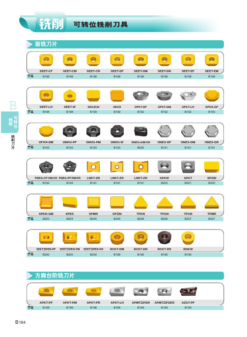
PVD涂层
YBG202 YBG205 YBG302 YBG152 YBG252
金属 陶瓷
YNG151C YNG151
硬质合金
B
可转位 铣削
铣削刀片
刀片外形
型 号 L
APKT11T304-PF APKT11T308-PF APKT11T312-PF APKT11T316-PF APKT160408-PF APKT11T304-PM APKT11T308-PM APKT11T312-PM APKT11T316-PM APKT160408-PM APKT11T304-PR APKT11T308-PR APKT11T312-PR APKT11T316-PR APKT160408-PR APKT11T304-LH APKT11T308-LH APKT160408-LH
YBM251 YBM253 YBM351 YBG102 YBD152 YBD252
PVD涂层
YBG202 YBG205 YBG302 YBG152 YBG252
金属 陶瓷
YNG151C YNG151
硬质合金
刀片外形
型 号 L
OFKT05T3-DF
5.26
YC30S
YD051
ØI.C
12.7
S
3.97
ød
4.4
R
0.5
○ ★
OFKT05T3-DM
5.26
12.7
3.97
4.4
0.5
○
★ ★
★
OFKT05T3-LH
5.26
12.7
3.97
4.4
0.5
★主推牌号备库存
●可选牌号备库存
○按订单生产
机械手刀库说明

预置值
1(刀套里所装刀具号) 2(刀套里所装刀具号) 3(刀套里所装刀具号) 4(刀套里所装刀具号) 5(刀套里所装刀具号) 6(刀套里所装刀具号) 7(刀套里所装刀具号) 8(刀套里所装刀具号) 9(刀套里所装刀具号) 10(刀套里所装刀具号) 11(刀套里所装刀具号) 12(刀套里所装刀具号) 13(刀套里所装刀具号) 14(刀套里所装刀具号) 15(刀套里所装刀具号) 16(刀套里所装刀具号) 17(刀套里所装刀具号) 18(刀套里所装刀具号) 19(刀套里所装刀具号) 20(刀套里所装刀具号) 21(刀套里所装刀具号) 22(刀套里所装刀具号) 23(刀套里所装刀具号) 24(刀套里所装刀具号) 24
不使用 外接按钮 使用 使用
没有感应 无 常开型 常开型 常开型 常开型 无效 否 提示 不允许
使用 面板按钮 不使用 不使用
感应 有 常闭型 常闭型 常闭型 常闭型 有效 是 不提示 允许
机械手正在动作标志 刀库正在回零状态
KAPA 参数使用时的注意事项: 1、 系统处于正常运行时,请确保 K0000、K0001、K0002、K0003、K0004、 K0005、K0006、 K0007、K0052、K0107 的状态为 0,否则有可能导致意外 发生。 2、 修改了 K0010 参数必须重新启动系统后才生效,当 K0010=0(即:不使 用刀库)时 K0100、K0101、K0102、K0103、K0104、K0105、K0106、K0107、 K0110、K011 设置无效。 3、 当 K0010=1(即:刀库使用有效)时,K0082 设置无效。 4、 当 K0082=0(即:不使用刀具夹/紧装置)时,K0081 设置无效。 5、 K0060 设置时的注意事项:
预留
识别和解决八种常见的刀片失效模式

识别和解决八种常见的刀片失效模式刀片失效对生产有不利影响,刀片反复承受着巨大应力,导致磨损和损耗,会降低制造商的加工精度和生产率。
刀片的早期检查对确定失效根源至关重要,此时更易于观察和报告。
若不采取这些重要步骤,就有可能混淆不同类型的失效模式。
为了方便刀片检查,可以使用立体显微镜。
后刀面磨损后刀面正常磨损是最容易被预见的刀具失效类型。
后刀面磨损一般很均匀,随着加工材料磨损切削刃逐渐显现,类似于刀刃变钝。
当工件中坚硬的细微夹杂物或加工硬化的材料切入刀片时,会出现正常后刀面磨损。
产生这种磨损的原因包括低速切削时的磨料磨损和高速切削时的化学反应。
识别正常后刀面磨损时,会发现刀片沿切削刃会形成一个相对均匀的磨痕,有时工件上的金属会擦伤切削刃,夸大了刀片磨痕的表观尺寸。
为了减缓后刀面正常磨损,需采用不会发生微崩的最硬刀片材质等级,并且使用最轻快的切削刃来减少切削力和摩擦。
在切削耐磨材料(如球墨铸铁、硅铝合金、高温合金、热处理后的沉淀硬化(PH)不锈钢、铍铜合金及钨硬质合金)以及在切削非金属材料(如玻璃纤维、环氧树脂、强化塑料和陶瓷)时常出现快速磨损。
后刀面的快速磨损会降低刀具寿命,无法达到15分钟的典型切削时间。
后刀面快速磨损的表现类似于正常磨损。
为了避免后刀面的快速磨损,需选择更耐磨、更坚硬或镀层硬质合金刀片材质等级,并确保使用适当的冷却液。
月牙洼磨损月牙洼磨损常见于铁基或钛基合金的高速加工中,属于刀片溶解到工件切屑中的热/化学磨损问题。
扩散磨损与磨料磨损共同作用造成了月牙洼,在加工基和钛基合金时,工件切屑中的热量会使硬质合金的成分溶解并扩散到切屑中,造成刀片顶部产生月牙洼。
月牙洼最终增大至足以使后刀面发生微崩和变形,甚至可能导致快速的后刀面磨损。
积屑瘤由于切削区存在化学亲和性、高压及高温,使工件碎片通过热压焊结到切削刃上,产生积屑瘤。
积屑瘤最终会脱落,有时随刀片碎片一同脱落,从而导致微崩和快速的后刀面磨损。
模具常用刀片介绍

清角刀片系列一
• 11型:
• APMT1135PDER HP-7025:适合加工钢件\铸铁.
APMT1135
• APMT1135PDER HP-7022:表面呈红色,新的含硅涂层,适合加工钢件, 表现出良好的耐崩性和耐磨性.
• 新建文件夹 (4)\7022、7225和VP15TF 16R0.8对比.xls
寿命长.尤其在加工侧壁时表现出良好的光 洁度,可替代山特R390-11T308M-PM 1030/530 刀片. 此刀片 配SA011R刀杆。
AOMT1136
清角刀片系列三
• APKT11T308E MP-7025 • 加工钢件用,在槽型跟刃口设计上跟1135有
区别,切削时更加轻快,更耐崩,在使用 寿命上表现突出. 配SAP11R及TAP11T3R刀杆。
• RDEWT0802MO HP-7012 加工高硬度钢件,可达HRC50. 使用高硬度刀片时.线速度尽量调低,Vc=6080M/Min.即降低转速,余量控制在0.15-0.25mm之 间.
RPEW0802
圆刀片系列五(精加工)
• R5/R6精加工刀片:
• RCKT10T3MO PL30
• RCKT1204MO PL20/PL25/PL30 模具精加工刀片,替代山特R6-530刀片,在通用性,稳定性方
•
HRC45度以上材料加工(HP7012 )
• 配刀盘:463X13Q22(锐耐克)
•
KXP13-63-22(SKIF)
• 编制程序:63R2
• 可替代东芝WPMT080615ZSR AH120.刀片
• 刀头可以通用,在使用寿命相同情况下性价
• 比更佳.
• 可替代可乐易WDKT130520 ZDSR-MH PC3525
美国麦克尼安机械与工具公司产品维修部件手册说明书

3655-251-0003/2011Please read and save this Repair Parts Manual. Read this manual and the General Operating Instructions carefully before attempting to assemble,install, operate or maintain the product described. Protect yourself and others by observing all safety information. The Safety Instructions are contained in the General Operating Instructions. Failure to comply with the safety instructions accompanying this product could result in personal injury and/or property damage! Retain instructions for future reference . AMT reserves the right to discontinue any model or change specifications at any time without incurring any obligation.©2006 American Machine & Tool Co., Inc. of PA, A Subsidiary of The Gorman-Rupp Company, All Rights Reserved.Periodic m aintenance and inspection is required on all pum ps to insure proper operation. Unit m ust be clear of debris and sedim ent. Inspect for leaks and loose bolts. Failure to do so voids warranty.SELF-PRIMING SPRINKLER/BOOSTER PUMPSRefer to pump manual 1808-634-00for General Operating and Safety Instructions.DescriptionThese self-priming (to 20 ft. lift) lawnsprinkler pumps are equipped with a check valve to assist in positive priming, a high performance closed impeller, a Buna-N mechanical seal to prevent leakage, and a continuous duty motor.Pumps are designed for higher pressure applications such as lawn sprinkling,spraying irrigation, also draining andgeneral de-watering applications. Casing working pressure to 150 psi (1034 kPa).Handles fluids from 40º to 180º F (4º to 82ºC). For use with nonflammable, non-abrasive liquids compatible with pump component materials.MaintenanceMake certain that this unit isdisconnected frompower source before attempting to service or remove any component!MECHANICAL SEAL REPLACEMENT Refer to Seal Replacement figures 2, 3. IMPORTANT: Always replace both seal seat (Ref. No. 6) and seal head (Ref. No. 7)to insure proper mating of components!Also, impeller seal (Ref. No. 22) (where applicable) should be replaced anytime impeller fastener (Ref. No. 23) has been removed.1.Unthread fasteners (Ref. No. 16) and remove pump casing (Ref. No. 14),casing seal (Ref. No. 5), and flapper valve (Ref. No. 13) from adapter (Ref.No. 4).2.Unthread fasteners (Ref. Nos. 12 and 17) and remove volute (Ref. No. 10)from adapter.3.Remove impeller fastener, impeller seal (where applicable), and impeller (Ref. No. 9).4.Shaft sleeve (Ref. No. 21) (where applicable) and seal head can now be pulled from shaft.IMPORTANT: Care should be taken to insure that the same number of shim washers (Ref. No. 8) are replaced behind impeller as were removed. These shim washers are located directly behindimpeller. These washers as well as impeller key (Ref. No. 24) (where applicable)become loose as impeller is removed.NOTE: Some motors (Ref. No. 20) use an open end 7/16" wrench across flats on rear of motor shaft (remove bearing cap foraccess) to prevent shaft from turning. Othermotor shafts have a screwdriver slot instead of flats.5.Unscrew fasteners (Ref. No. 23). Remove mounting base and handle (Ref. No. 18 &2) (where applicable), and adapter from motor mounting face.6.Push seal seat from back of adapter recess with a screwdriver.7.Clean adapter recess before inserting a new seal seat.The precision lapped faces on mechanical seal are easily damaged.Handle your replacement seal carefully.8.Carefully wipe polished surface of new seal seat with a clean cloth.9.Wet rubber portion of seal seat with a light coating of soapy water.10.Press new seal seat squarely into recessin adapter. If seal seat does not press squarely into cavity, it can be adjusted in place by pushing on it with a piece of pipe. Always use a piece of cardboard between pipe and seal seat to avoid scratching polished surface.11.After seal seat is in place, ensure that it isclean and has not been marred.NOTE: If removed, slide slinger washer (Ref.No. 1) onto shaft until it is located approxi-mately 1/8" from face of motor bearing hub.ing a clean cloth, wipe shaft/shaftsleeve and make certain that it is perfectly clean.13.Secure foot and handle (where applicable)and adapter on motor mounting face.Carefully guide motor shaft through seal seat.14.Replace shaft sleeve and impeller key(where applicable).IMPORTANT: Before installing new shaftsleeve, apply a bead of non-hardening, pliable sealant (such as Permatex® Form-A-Gasket®No. 2) to motor shaft shoulder.15.Wet inside rubber portion of new seal headwith a light coating of soapy water. Slide head onto shaft/shaft sleeve. Seal head and seal seat will meet. Reinstall any shims which have been removed. (See Shim Adjustment).16.Install impeller and reassemble pump.17. A short "run-in" period may be necessaryto provide completely leak-free seal operation.SHIM ADJUSTMENT (365 SERIES ONLY)When installing a replacement impeller (Ref.No. 9) or motor (Ref. No. 20), it may benecessary to adjust number of shims (Ref. No.8) to insure proper running clearance between impeller and volute (Ref. No. 10). Proceed as follows:NOTE: A proper running clearance is less than 0.010" (face of impeller to mating face of volute).1.For impeller replacement, add one (0.010")shim in addition to those removed originally.2.For motor replacement, add two (0.010")shims in addition to those removed during disassembly.3.Reassemble the pump as described in steps 16 and 17 (above).IMPORTANT: Ensure that volute is snugly in place and check shaft to make sure it is turning freely (use 7/16" wrench or screwdriver to turn shaft). If it turns freely, check to ensure that adapter (Ref. No. 4) and volute are fitted metal-to-metal where they meet on outside. If they are not metal-to-metal, tighten fasteners (Ref. No.12 & 17) and recheck shaft for free turning.Tighten carefully, turning shaft while tightening so that motor bearings are not damaged in the event that too many shims were installed. If shaft seizes before fasteners are completelytight, disassemble pump and remove one (0.010") shim and repeat reassembly.4.When proper clearance is obtained,reassemble.3655-95 thru 3657-95 and S pecifications Information and Repair Parts Manual 3790-95 thru379L-95 Please provide following information:-Model number-Serial number (if any)-Part descriptions and number as shown in parts listRepair Parts List3790 (3/4 HP)3791 (1 HP)3792 (1½ HP)3793 (2 HP)379G (3/4 HP)379H (1 HP)3797 (1½ HP)379K (2 HP)379A (1 HP)379B (1½ HP)379C (2 HP)379D (3 HP)3657 (5 HP)Description379F (1 HP)379J (1½ HP)379E (2 HP)379L (3 HP)3655 (5 HP)3656 (7½ HP)Qty.1Slinger washer1534-000-001534-000-001534-000-001534-000-001470-093-001470-093-001 2Handle1515-000-001515-000-001515-000-001515-000-00 -- -- 1 3Fastener******4 4Adapter1608-011-011608-011-011608-011-011608-011-013655-030-093655-030-091 5Casing Seal - Buna N (std)1610-000-001610-000-001610-000-001610-000-002186-000-002186-000-001 - Viton (opt)1610-001-001610-001-001610-001-001610-001-002186-001-002186-001-006 & 7† Shaft seal assy. -Buna N (std)1640-161-961640-161-961640-161-961640-161-961640-163-901640-163-901† - Viton (opt)1640-161-971640-161-971640-161-971640-161-971640-163-911640-163-91 8Impeller Shim pkg. -- -- -- -- 1664-000-901664-000-901 9Impeller379A-011-09379B-011-09379C-011-09379D-011-093655-012-093656-012-091 10Volute379B-150-09379B-150-09379D-150-09379D-150-093655-150-093655-150-091 11Washer******2 12Fastener******2 13Flapper valve -Buna N (std)1609-002-001609-002-001609-002-001609-002-001609-002-001609-002-001 -Viton (opt)1695-011-901695-011-901695-011-901695-011-901695-011-901695-011-90 14Casing2111-001-012111-001-012111-001-012111-001-012112-001-022112-001-021 15Pipe plug******2 16Fastener******4 17Fastener******1 18Foot1506-000-001506-000-001506-000-001506-000-00 -- -- 1 19Fastener******1 20Motor - 1 Phase ODP1626-010-001626-011-001626-012-001626-024-00 -- --1 - 3 Phase ODP1626-014-001626-015-001626-016-001626-025-00 -- --- 1 Phase TEFC1626-069-001626-050-001626-070-001626-071-001626-078-00 --- 3 Phase TEFC1626-077-001626-053-001626-054-001626-072-001626-044-001626-045-00 21Shaft sleeve -- -- -- -- 1472-000-001472-000-001 22Impeller seal -- -- -- -- 1471-020-001471-020-001 23Impeller fastener1784-001-091784-001-001784-001-001784-001-001756-000-001756-000-001 24Impeller key -- -- -- -- 1471-030-001471-030-001 (*)Standard hardware item, available locally(†)Seal head (Ref. No. 7) and seat (Ref. No. 6) available as a set only. When replacing a shaft seal assembly, a new impeller seal (Ref. No. 23) should also be used. (Model series 365 only).-2-。
蒂Literalmate 电动刮其 flag 系列 5000 多功能刮其说明书

Product PictureShaver series 5000SteelPrecision bladesPower Adapt sensor360-D Flexing headsIntegrated pop-up trimmerS5579/71Powerful shave, gentle on skinwith SkinIQ T echnologyThe Philips Series 5000 delivers a powerful shave, cutting now even more hair per stroke*. Equipped with advanced SkinIQ technology, the shaver senses and adapts to your hair density, for improved skin comfort.A powerful shaveMore cutting performance in every strokeFollows the contours of your faceGuides hair into the optimal cutting positionSkinIQ technologyA shaver with the power to tame beardsFor a convenient shavePowerful cleaning pod for maintenance and hygieneChoose a convenient dry or refreshing wet shaveEven-up your mustache and sideburns60 minutes of shaving from a 1-hour chargeFully charged in one hourThe electric shaver with an Eco passportA more intuitive shaving experienceWet & Dry electric shaver S5579/71 Highlights SpecificationsSteelPrecision bladesPowerful yet gentle, the 45 self-sharpening SteelPrecision blades on this Philips shaver complete up to 90,000 cutting actions per minute, cutting more hair per stroke** for a clean, comfortable finish.Power Adapt sensorThe electric shaver has intelligent facial-hair sensor that reads hair density 125 times per second. The technology auto-adapts cutting power for an effortless and gentle shave.360-D Flexing headsDesigned to follow the contours of your face, this Philips electric shaver has fully flexible heads that turn 360° for a thorough and comfortable shave.Hair-Guide precision headsThis new shape precision shaver is enhanced with hair guiding channels for optimal cutting and skin comfort.Cable-free Quick Clean Pod10x more effective than cleaning with water**, the powerful cleaning pod thoroughly cleans and lubricates your shaver in just 1 minute. Using it helps maintain shaver performance and increase hygiene.Shave wet or dryA wet and dry shaver that adapts to yourpreference. Choose a convenient dry shave, orpair with your favourite foam or gel for arefreshing wet shave.Pop-up trimmerRefine and define your mustache andsideburns with the pop-up trimmer—andcomplete your look with ease.60 minutes of cordless shavingA shaver for at home or on-the-go. Get 60minutes of shaving time from a 1-hour charge,or plug it in for instant and continuous power.1-hour charging timeFully charge your Philips shaver in just 1 hourwith the powerful and energy efficient lithium-ion battery. In a hurry? Plug in your shaver for 5minutes and get enough power for 1 full shave.Sustainable shaving innovationAt Philips, we drive sustainability in all aspectsof product creation. With shaving bladesproduced using 100% renewable electricityand packaging made with recyclable materials,all shavers come with an Eco passport.LED displayYou can easily see how much power is left withthe 3-level LED display. Your Philips shavernot only tells you when it's time to charge, italso has indicators for locking, cleaning andreplacing the head.Shaving PerformanceShaving system: SteelPrecision bladesContour following: 360-D Flexing headsSkinIQ technology: Power Adapt sensorEase of useWet & Dry: Wet and dry useDisplay: LED display, Battery level indicator,Travel lockCleaning: One-touch open, Fully washableDesignHandle: Rubber gripColor: Electric BlueShaving heads: AngularPowerRun time: 60 minutesCharging: 1 hour full charge, 5 min quickchargeAutomatic voltage: 100-240 VStand-by power: 0.04 WMax power consumption: 9 WBattery type: Li-ionService2-year warrantyReplacement head SH71: Replace every 2 yrswith SH71AccessoriesQuick Clean Pod: 1 cartridge included, YesIntegrated pop-up trimmerMaintenance: Cleaning brushTravel and storage: Travel case* Tested versus Philips Series 3000.* * Comparing shaving debris after using cleaning fluidvs. water in the cartridge© 2022 Koninklijke Philips N.V.All Rights reserved.Specifications are subject to change without notice. Trademarks are the property of Koninklijke Philips N.V. or their respective owners.Issue date 2022‑03‑31 Version: 3.0.1。
刀具一览表
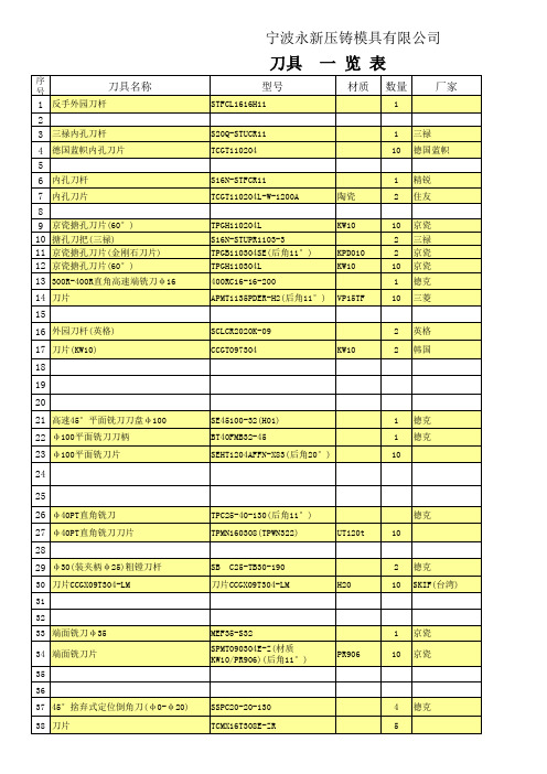
德克 德克 韩国KORLOY 德克
德克 德克 德克 德克 德克 德克 德克 德克 德克 德克 德克
PCD-B09 HTi10
金刚石刀片(半精)(加工铝B390.0)(60° TP090204 ) 刀片(不好)(切铝) 刀片(好)(切铝) APKT160408LN APKT1604PDFR-MA3
PCD-B09 H20 H01
PCD-B09 PCD-B09
6 10 1
山西登塔钻石 象山锐利刀具 德克
2007.12
购买日期 单价(元)
279.51 47.38 220.00 42 2008.7.18 2007.12.18 2007.12.18 2008.7.18 2008.03.02 2008.03.02 35 213 138.5 35
DBJ-16 DBJ-16 TP090204 TP090304 TP090304 400RC32-40-200
PCD PCD PCD
1 1 10 10 10 2 1 2 1 1 10 1
德克 德克 宏盛 宏盛 德克 德克 德克 德克 德克 韩国KORLOY 韩国KORLOY 韩国KORLOY
TP30 C25-40-120 MGEHR2020-2.5 MGMN400-M MGEHR2020-4
53 镗头刀柄 BT40-DCK6-55 ) 54 金刚石刀片(半精)(加工铝B390.0)(60° TP090204(后角11°) 镗刀刀片(60°) 55 56 四刃立铣刀φ 12(镀钛) 57 二刃立铣刀φ 8(镀钛) φ 12-S4-100L(T42-1212) φ 8-S2-100L(T42-1212) TPGH090204L-FS
宁波永新压铸模具有限公司
刀具
序号
刀具培训

刀类产品主要有U钻刀片、U钻配件螺丝、刀片、合 金铣刀、螺纹刀片、丝锥、数控刀片、铣刀片等。
我们公司目前使用的刀的型号(一)U钻刀片
HRWL002295 HRWL002296 HRWL002297 HRWL003644 HRWL004039 HRWL003764 HRWL003995 HRWL004167 U钻 U钻刀片 U钻刀片 刀具\刀\880-D1900L25-03 刀具\刀\880-0305H-C-LM1144 刀具\刀\880-0303W06H-P-MS2044
我们公司目前使用的刀的型号(三)割槽刀片、螺纹刀片
HRWL002103 HRWL003580 HRWL002483 HRWL003534 HRWL001993 割槽刀片 割槽刀片 括刀片 括刀片 螺纹刀片 螺纹刀片 螺纹刀片 螺纹刀片 刀具\刀\GVR300-020C GVR300C PR930 刀具\刀\GVFR350-040C 刀具\刀\BS1010 刀具\刀\BS1018 刀具\刀\16IR14NPT/BMA 刀具\刀\16IR 16UN BMA 刀具\刀\16IR14W/BMA 刀具\刀\16IR11W/BMA
我们公司目前使用的刀的型号(七)其他
HRWL002152 HRWL002188 HRWL000826 HRWL003723 HRWL002167 HRWL000674 HRWL002693 HRWL002484 HRWL002154 HRWL003009 HRWL003350 ER扳手 扳手 板牙 扁锉 弹簧筒夹 割刀 键槽铣刀 括刀柄 拉钉 螺槽丝攻 螺纹梳刀片 锁刀座 刀具\刀\ER 32UM 刀具\刀\BT40-KPU13(钻夹头刀柄) 刀具\刀\M12 刀具\刀\5*180 刀具\刀\ER32-12 刀具\刀\YT15 刀具\刀\¢6.7 刀具\刀\¢25MM 刀具\刀\JISB6339,BT40-45° 刀具\刀\EX-SUS-SFT15116M4*0.7,OH2 刀具\刀\14-14W/MT7 刀具\刀\BT40
MT1000A的APS倒换问题说明
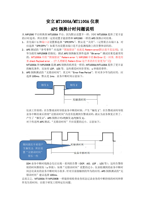
安立MT1000A/MT1100A仪表APS倒换计时问题说明从MP1590平台转换到MT1000A平台,因为默认设置不一样,同时MT1000A提供了更丰富的计时选项,所以需要一定的设置才能获得和MP1590一样的APS倒换计时结果。
1、首先端口1和端口2设置都选择“SFP/SFP+”,默认是“关闭”,(记得要点击端口2,对应选择“SFP/SFP+”)如果不改设置该端口是不会监测线路上的告警和误码的。
2、APS测试的“参考事件”应选择“图案错误”也就是Pattern error[默认值不是这项],以华为使用MP1590B的情况,测试APS倒换触发事件选择“Bit error”测试结果是最常用的,MT1000A中的“图案错误”Pattern error与MP1590中的Bit Error是一回事, 都是用来check Payload error。
[个人理解是Pattern Error这个术语在行业更为广泛]MT1000A和MP1590B监测APS倒换的机理是一样的。
MT1000A/MT1100A提供了更丰富的触发条件,比如有LOF,LOS等,这些都是时间非常短,u秒级的事件。
3、APS倒换测试的“无错误时间”,英文叫“Error Free Period”,针对多少华为的应用,应选择100ms,默认是1ms。
业务中断时间示意如下:触发1 触发2仪表工作原理:在告警或误码导致业务中断的时候,产生“触发1”。
在告警或误码导致业务中断结束后持续“无错误时间”内没有监测到告警或误码,就认为业务恢复正常了。
产生了“触发2”,APS倒换计时=T(触发2)-T(触发1)。
对于传送网APS测试,“无错误时间”不应设置的过小,示意如下:期间我们不希望产生触发2,所以设置“无错误时间”要长一些SDH业务中断时线路会先后出现一系列的告警(OOF,AIS,LOF ,LOS等),这些告警持续的时间都很短(u秒级),如果“无错误时间”设置的过小,仪表检测到的业务中断时间会比真实的业务中断时间小很多。
罗塔特丽姆(Rotatrim) 旋转刀具 PT系列 说明书

PowerTechPT SERIESENGINEERED FOR TOTAL CUT PRECISION© 2014. Copyright Rotatrim LimitedPT SERIES SIZE GUIDE (T SERIES TRIMMER SHOWN)PT SERIES MATERIALS CUT GUIDEAluminium 0.5mm FoilPhotocopier Paper Our trimmers will cut Cutting edge technology. Minimum effort.P T 650P T 950P T 1250P T 1550P T 1850P T 2150P T 2500PT SERIES CUT LENGTH7MODEL SIZES TO CHOOSE FROM2SPEED VARIANTS TO CHOOSE FROMFREE MATERIAL COMPATIBILITY SERVICE3.0mmCUT CAPACITY PT 650 - PT 1850UP TOPowerTech PT SERIES4 Power driven large format, precision, robust trimmer4 Optional high speed and normal speed variants4 Foot pedal operation with automatic safety clamp enables a single userto easily position and cut large materials4Cuts a wide range of materials without adjustment4Overload protection feature4Range of cutting lengths from 0.65 metres up to 2.5 metres4Ultra hard Sheffield D2 ‘Tool Steel’ self-sharpening, precisionengineered blades4Large single square stainless steel guide rail completely eliminateshead swivel4Aluminium baseboard, end frames, head and side rule4Also available: Stand & Waste Collector to fit the model of your choiceEngineered for Total Cut PrecisionMachine Speed OptionsThespeed variants. The normal speed variant cuts at 0.5m/sec and hasmore torque so is better for trimming heavier materials. The highspeed version cuts at 1.0m/sec and is better where lighter materials(generally up to 1.0mm) in thickness are being cut. On the high speedmachine, it is also possible to remove the RCC plate (as it is used forthinner materials), to allow for a cut to be performed in both directions.A range of accessories can be purchased separately including ExtendedRule Kits; Roll Dispenser; Stand & Waste Collector.Visit for details.。
海科特加工中心自动刀具交换(ATC)的故障分析及解决方案
海科特加工中心自动刀具交换(ATC)故障分析及解决方案作者:庄晨单位: 扬州柴油机有限公司金加工分厂职务:电器工艺师职称:工程师导言:通过时自动刀具交换(ATC)动作步骤分折,来对进行故障析, 提出解决方案.本厂于2004年度引进具有世界先进水平的德国CWK(海科特)卧式加工中心五台,德国CWK(海科特)是属于瑞士一家公司的德国分厂,位于美丽的德国乡镇开米利斯,其前身为东欧集团专门生产加工中心的工厂,全盛时期,仅工人就有7000多人,她的生产水平在世界处于中上水平。
本厂引进CWK-500加工中心适合于加工所有复杂箱体形状的工件,我厂以五台CWK(海科特)卧式加工中心为主组成了一条箱体类柔性生产线,按工艺节拍分为OP40,OP50,OP60A,OP60B,OP90.它们有工件交换装置 (托盘交换装置) ,采用链式刀库,可装刀60把。
OP90采用 HSK 100刀具.其余采用SK 50刀具.其中OP50,OP60A,OP60B,有激光刀具折断检测装置, OP60A,OP60B是数控回转工作台(B轴)分度精度为0.001°,其余为分度工作台, 分度精度为1°. 主轴中心内冷压力由编程控制可调.OP90.是精加工机库采用液压保持夹具,,配有雷利速探头,可动态加工补偿.本人有幸参加了到德培训、验收的全过程。
在德国Training engineer们的理论与实践互相交替、高效率、强节奏的培训下,我们在开米利斯,度过了紧张而充实的28天。
设备从安装、调试、试生产、生产至今有两年许,其由也发生了不少故障。
根据我的维修记录,故障主要出在自动刀具交换(ATC)部分,请看下图:(图1)注:1故障统计不包括操作故障.2:下面所提元件皆为设备号,不是PLC输入编号.3: 正反转是人正对设备而言.4:由于种种原因S7程序一直未能跟机床相互通信,没有获得梯形图,海科特提供资料是语句表,德文的.所以未能附上图,对此深表遗憾。
