abb信号继电器
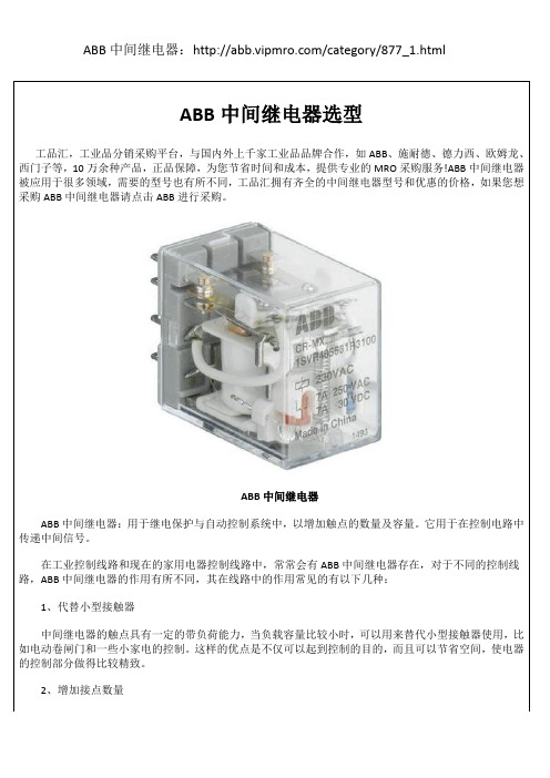
ABB中间继电器

型号 环境温度范围
抗震性
标准
型号 产品标准 低压指令
CR-MX...2 300 V AC F 触点与线圈之间 5.8 mm 触点与线圈之间 3.5 mm III 2
1SVR405631R4100
CR-MX024DC2L
24 V DC
1SVR405631R1100
CR-MX048DC2L
48 V DC
1SVR405631R6100
CR-MX110DC2L
110 V DC
1SVR405631R8100
CR-MX024AC2L
24 V AC
1SVR405631R0100
48 V DC
1SVR405631R6000
CR-MX110DC2
110 V DC
1SVR405631R8000
CR-MX024AC2
24 V AC
1SVR405631R0000
CR-MX110AC2
110 V AC
1SVR405631R7000
CR-MX230AC2
230 V AC
1SVR405631R3000
CR-P/M 42B 24-60 V DC
CR-P/M 42BV 24-60 V DC
CR-P/M 42C 110 V DC
CR-P/M 42CV 110 V DC
RC回路 - 滤波和灭弧
CR-P/M 52B 6-24 V AC/DC CR-P/M 52D 24-60 V AC/DC CR-P/M 52C 110-230 V AC/DC
线圈电阻 (20℃时) 160 Ω 650 Ω 2600 Ω 11000 Ω 184 Ω 4550 Ω 14400 Ω
线圈电阻误差
信号继电器概述
信号继电器继电器是自动控制系统中常用的电器,它用于接通和断开电路,用以发布控制命令和反映设备状态,以构成自动控制和远程控制电路。
各个领域的自动控制系统无一不采用继电器。
铁路信号技术中广泛采用继电器,称为信号继电器(在铁路信号系统中,可简称继电器),是铁路信号技术中的重要部件。
它无论作为继电式信号系统的核心部件,还是作为电子式或计算机式信号系统的接口部件,都发挥着重要的作用。
继电器动作的可靠性直接影响到信号系统的可靠性和安全性。
一、信号继电器概述信号继电器是用于铁路信号中的各类继电器的统称,是各类信号控制系统不可缺少的重要器件。
(一)、铁路信号对继电器的要求信号继电器作为铁路信号系统中的主要(或重要)器件,它在运用中的安全、可靠就是保证各种信号设备正常使用的必要条件。
为此,铁路信号对继电器提出了极其严格的要求,具体如下:(l)动作必须可靠、准确;(2)使用寿命长;(3)有足够的闭合和断开电路的能力;(4)有稳定的电气特性和时间特性;(5)在周围介质温度和湿度变化很大的情况下,均能保持很高的电气绝缘强度。
具体要求见《信号维修规则技术标准》11继电器11 . 1通则。
按照工作的可靠程度,信号继电器可分为三级:一级继电器:绝对不允许发生前接点与动接点之间的熔接;衔铁落下与前接点的断开由衔铁及可动部分的重量来保证;当任意一组前接点闭合时,所有后接点必须全部断开,反之亦然;衔铁处于落下位置时,应该稳定的工作,后接点压力主要由重力作用产生;有较高的返还系数:轨道继电器不小于50%,一般继电器不小于30%。
二级继电器:衔铁依靠本身重量或接点弹片反作用力返还;返还系数不小于20%;当任意一组前接点闭合时,所有后接点必须全部断开,反之亦然。
三级继电器(电码型和电话型):衔铁返还与后接点的压力均由动接点弹片的反作用力产生;前后接点均有熔接的可能。
在信号设备的执行电路中,如果继电器由于工作不正常而不能断开前接点时,将严重威胁行车的安全,故设计时均采用一级继电器,又由于一级继电器的高度可靠性。
ABB 电流和电压监控继电器系列说明书
Measuring and monitoring relays Single- and three-phase2 2CDC112184B0201Current and voltage monitoring relays Monitoring the parameters of single-phase mainsCurrent monitoringThe ABB current monitoring relays CM-SRS.xx reliably monitor currents which exceed or fall below the selected threshold value. The functions overcurrent or undercurrent monitoring can be preselected. Single- and multifunction devices for monitoring of direct or alternating currents from 3 mA to 15 A are available.Applications of current and voltage monitoring relays in single-phase mainsCurrent window monitoring (I min , I max )The window monitoring relay CM-SFS.2x is the right solution if the application requires the simultaneous monitoring of over- and undercurrents.Voltage monitoringThe ABB voltage monitoring relays CM-ESS.xx are used to monitor direct and alternating voltages within a range of 3 to 600 V. Over- or undervoltage detection can be preselected.Voltage window monitoring (U min , U max )For the simultaneous detection of over- and undervoltages, the window monitoring relay CM-EFS.2 can be used.For the monitoring of currents and voltages in single-phase AC/DC systems, ABB’s CM range contains a wideselection of powerful and compact devices all in only 22.5 mm wide. This meauring range includes current and voltage monitoring relays for over- and undercurrent protection, over- and undervoltage protection and phase loss monitoring – from 3 mA to 15 A and from 3 V to 600 V. Incorporating ABB’s long-term experience the CM range provides highestsafety and reliability for your electric installation.2CDC112184B0201 3Three-phase monitoring relays Monitoring the parameters in three-phase mainsMonitoring for over- and undervoltageAll electric devices can be damaged when operated continuously at voltages over or under their rated values. An overvoltage could potentially cause heating within the device. If the temperature is unduly high, component parts and thus whole devices or installations may fail or may be destroyed. Undervoltages involve the risk that the switching elements reach an undefined state. In this case, parts of the installation still function, but not others. This misoperation can result in damage of the product or installation. In the worst case, wrong voltages may even cause harm to the operating personnel.Applications for three-phase monitoring relays in three-phase mainsPhase unbalance monitoringIf the supply by the three-phase system is unbalanced due to uneven distribution of the load, the motor will convert a part of the energy into reactive power. This energy gets lost unexploited; also the motor is exposed to higher thermal strain. Other thermal protection devices fail to detect continuing unbalances which can lead to damage or destruction of the motor. The CM range three-phase monitoring relays with phase unbalance monitoring can reliably detect this critical situation.Phase failure detectionIn case of a phase loss, undefined states of the installation are likely to occur. E.g. the startup process of motors is disturbed. All three-phase monitoring relays of the ABB CM range detect a phase loss as soon as the voltage of one phase drops below 60 % of its nominal value.Phase sequence monitoringA change of the phase sequence during operation or an incorrect phase sequence that is applied at start-up will cause a three-phase motor to run with reverse rotation. Certain motors when operated in the reverse direction will cause severe damage to connected loads such as pumps, screw compressors and fans. Especially for non-fixed or portable equipment, such as construction machinery, phase sequence detection prior to the start-up process is highly recommended. ABB offers three-phase monitoring relays with selectable phase sequence monitoring. This provides the capability of ignoring phase sequence conditions for applications, such as motors with forward and reverse rotation, where the phase sequence is Only reliable and continuous monitoring of three-phase networks guarantees trouble-free and economic operation of machines and installations. Thus, the three-phase monitoring relays of the CM range monitor the phase voltages, phase sequence, phase unbalance and phase loss.Interrupted neutralUnder normal conditions, individual phase voltages are equal and the load causes the individual phase currents to vary. Systems that have neutral conductors accommodate this variation by a compensating current flow through the neutralconductor. If the neutral conductor breaks, the compensating current can no longer flow. As a result, the voltage is divided asymmetrically on the individual phases. This means that over- and undervoltages are produced in the individual phases and these can damage or even destroy the connected consumers. ABB offers three-phase monitoring relays that monitor the neutral conductor for interrupted neutral. The interruption of the neutral is detected by means of phase balance monitoring. Automatic phase sequence correctionThe new generation of ABB three-phase monitoring relays offers devices with automatic phase sequence correction. If phase sequence monitoring and phase sequence correction are activated, and in conjunction with a reversing contactor combination, it is ensured that for any non-fixed or portable equipment, e.g. construction machinery, the correct phase sequence is applied to the input terminals of the load.Current and voltage monitoring relays for single-phase AC/DC currentsCurrent monitoring relaysVoltage monitoring relaysCharacteristics of current monitoring relays−Monitoring of DC and AC currents (3 mA to 15 A)−TRMS measuring principle−One device includes 3 measuring ranges−Over- and/or undercurrent monitoring configurable 1)−CM-SFS.2 and CM-SRS.M: Latching function configurable−Hysteresis adjustable (3-30 %) or fixed hysteresis (5 %) 1)−Precise adjustment by front-face operating controls−Screw connection technology orEasy Connect Technology available−Housing material for highest fire protection classificationUL 94 V-0−Tool-free mounting on DIN rail as well as demounting−22.5 mm (0.89 in) width− 3 LEDs for status indication1) depending on deviceCharacteristics of voltage monitoring relays−Monitoring of DC and AC voltages (3-600 V)−TRMS measuring principle−One device includes 4 measuring ranges−Over- and/or undervoltage monitoring configurable 1)−CM-ESS.M and CM-EFS.2: Latching function configurable−Hysteresis adjustable (3-30 %) or fixed hysteresis (5 %) 1)−Precise adjustment by front-face operating controls−Screw connection technology orEasy Connect Technology available−Housing material for highest fire protection classificationUL 94 V-0−Tool-free mounting on DIN rail as well as demounting−22.5 mm (0.89 in) width− 3 LEDs for status indication1) depending on deviceApprovals forcurrent and voltage monitoring relaysA UL 508, CAN/CSA C22.2 No.14C GL(pending)D GOSTK CB SchemeE CCCL RMRSSingle-phase voltage and current monitoring relays protect sensitive equipment and control systems against undervoltage (brownout) or undercurrent events or overvoltage or overcurrent events. Different units with adjustable or fixed threshold values (trip points) are available.All devices are available with two different terminal versions. You can choose between the proven screw connection technology (double-chamber cage connection terminals) and the completely tool-free Easy Connect Technology (push-in terminals).Marks forcurrent and voltage monitoring relaysa CEb C-Tick4 2CDC112184B0201Single- / multifunctional monitoring relays for monitoring of three-phase mainsSinglefunctionalMultifunctionalThe reliable and continuous monitoring of three-phase networks guarantees trouble-free and economic operation of machines and installations.The most multifunctional devices in the EPR assortment are the CM-MPS/N monitoring relays for rated voltage levels up to 820 V AC and 400 Hz. Additionally a variety of economic and cost-efficient three-phase monitoring relays are offered in this range with specialized functionality.Most devices are available with two different terminal versions. You can choose between the proven screw connection technology (double-chamber cage connection terminals) and the completely tool-free Easy Connect Technology (push-in terminals).Characteristics−Monitoring of three-phase mains for phase sequence (canbe switched off), phase failure, phase unbalance over- andundervoltage 1)−TRMS measuring principle−Threshold values are adjustable as absolute values 1)−Powered by the measuring circuit−Precise adjustment by front-face operating controls−Screw connection technology orEasy Connect Technology available−Housing material for highest fire protection classificationUL 94 V-0−Tool-free mounting on DIN rail as well as demounting−S-range: 22.5 mm (0.89 in) width−N-range : 45 mm (1.78 in) width− 3 LEDs for status indication1) depending on deviceApprovalsA UL 508, CAN/CSA C22.2 No.14(CM-PVS.81 pending,not for CM-MPN.72)C GL(pending)D GOSTK CB Scheme(pending)E CCC(CM-PVS.81 pending)Marksa CEb C-Tick(CM-PVS.81 pending)2CDC112184B0201 56 2CDC112184B0201TypeRated control supply voltage Connection technologyMeasuring rangesOrder codeCM-SRS.11P24-240 V AC/DCPush-in terminals3-30 mA, 10-100 mA, 0.1-1 A1SVR 740 840 R0200110-130 V AC 1SVR 740 841 R0200220-240 V AC 1SVR 740 841 R1200CM-SRS.11S24-240 V AC/DCScrew terminals3-30 mA, 10-100 mA, 0.1-1 A1SVR 730 840 R0200110-130 V AC 1SVR 730 841 R0200220-240 V AC 1SVR 730 841 R1200CM-SRS.12S24-240 V AC/DCScrew terminals0.3-1.5 A, 1-5 A, 3-15 A1SVR 730 840 R0300110-130 V AC 1SVR 730 841 R0300220-240 V AC 1SVR 730 841 R1300CM-SRS.21S24-240 V AC/DCScrew terminals3-30 mA, 10-100 mA, 0.1-1 A1SVR 730 840 R0400110-130 V AC 1SVR 730 841 R0400220-240 V AC 1SVR 730 841 R1400CM-SRS.21P24-240 V AC/DCPush-in terminals 1SVR 740 840 R0400110-130 V AC 1SVR 740 841 R0400220-240 V AC 1SVR 740 841 R1400CM-SRS.22S 24-240 V AC/DCScrew terminals0.3-1.5 A, 1-5 A, 3-15 A1SVR 730 840 R0500110-130 V AC 1SVR 730 841 R0500220-240 V AC1SVR 730 841 R1500CM-SRS.M1P 24-240 V AC/DC Push-in terminals 3-30 mA, 10-100 mA, 0.1-1 A 1SVR 740 840 R0600CM-SRS.M1S Screw terminals 1SVR 730 840 R0600CM-SRS.M2S 0.3-1.5 A, 1-5 A, 3-15 A 1SVR 730 840 R0700CM-SFS.21P 24-240 V AC/DC Push-in terminals 3-30 mA, 10-100 mA, 0.1-1 A 1SVR 740 760 R0400CM-SFS.21S Screw terminals1SVR 730 760 R0400CM-SFS.22S0.3-1.5 A, 1-5 A, 3-15A1SVR 730 760 R0500CM-ESS.1P24-240 V AC/DCPush-in terminals3-30 V , 6-60 V , 30-300 V , 60-600 V1SVR 740 830 R0300110-130 V AC 1SVR 740 831 R0300220-240 V AC 1SVR 740 831 R1300CM-ESS.1S24-240 V AC/DCScrew terminals3-30 V , 6-60 V , 30-300 V , 60-600 V1SVR 730 830 R0300110-130 V AC 1SVR 730 831 R0300220-240 V AC 1SVR 730 831 R1300CM-ESS.1P24-240 V AC/DCPush-in terminals3-30 V , 6-60 V , 30-300 V , 60-600 V1SVR 740 830 R0300110-130 V AC 1SVR 740 831 R0300220-240 V AC 1SVR 740 831 R1300CM-ESS.1S24-240 V AC/DCScrew type terminals3-30 V , 6-60 V , 30-300 V , 60-600 V1SVR 730 830 R0300110-130 V AC 1SVR 730 831 R0300220-240 V AC 1SVR 730 831 R1300CM-ESS.1P24-240 V AC/DCPush-in terminals3-30 V , 6-60 V , 30-300 V , 60-600 V1SVR 740 830 R0300110-130 V AC 1SVR 740 831 R0300220-240 V AC 1SVR 740 831 R1300CM-ESS.1S 24-240 V AC/DCScrew type terminals3-30 V , 6-60 V , 30-300 V , 60-600 V1SVR 730 830 R0300110-130 V AC 1SVR 730 831 R0300220-240 V AC 1SVR 730 831 R1300CM-ESS.MP 24-240 V AC/DC Push-in terminals 3-30 V , 6-60 V , 30-300 V , 60-600 V 1SVR 740 830 R0500CM-ESS.MS Screw type terminals 1SVR 730 830 R0500CM-ESS.MP 24-240 V AC/DC Push-in terminals 3-30 V , 6-60 V , 30-300 V , 60-600 V 1SVR 740 830 R0500CM-ESS.MS Screw type terminals 1SVR 730 830 R0500CM-EFS.2P 24-240 V AC/DC Push-in terminals 3-30 V , 6-60 V , 30-300 V , 60-600 V 1SVR 740 750 R0400CM-EFS.2S24-240 V AC/DCScrew type terminals3-30 V , 6-60 V , 30-300 V , 60-600 V1SVR 730 750 R0400Current and voltage monitoring relays Ordering dataThree-phase monitoring relays Ordering dataType Rated control supply voltage =measuring voltage Interrupted neutral monitoring ConnectiontechnologyOrder codeCM-MPS.11P 3 x 90-170 V AC yes Push-in terminals1SVR 740 885 R1300CM-MPS.11S yes Screw terminals1SVR 730 885 R1300CM-MPS.21P 3 x 180-280 V AC yes Push-in terminals1SVR 740 885 R3300CM-MPS.21S yes Screw terminals1SVR 730 885 R3300CM-MPS.31P 3 x 160-300 V AC no Push-in terminals1SVR 740 884 R1300CM-MPS.31S no Screw terminals1SVR 730 884 R1300CM-MPS.41P 3 x 300-500 V AC no Push-in terminals1SVR 740 884 R3300CM-MPS.41S no Screw terminals1SVR 730 884 R3300CM-MPS.23P 3 x 180-280 V AC yes Push-in terminals1SVR 740 885 R4300CM-MPS.23S yes Screw terminals1SVR 730 885 R4300CM-MPS.43P 3 x 300-500 V AC no Push-in terminals1SVR 740 884 R4300CM-MPS.43S no Screw terminals1SVR 730 884 R4300CM-MPS.52P 3 x 350-580 V AC no Push-in terminals1SVR 760 487 R8300CM-MPS.52S no Screw terminals1SVR 750 487 R8300CM-MPS.62P 3 x 450-720 V AC no Push-in terminals1SVR 760 488 R8300CM-MPS.62S no Screw terminals1SVR 750 488 R8300CM-MPS.72P 3 x 530-820 V AC no Push-in terminals1SVR 760 489 R8300CM-MPS.72S no Screw terminals1SVR 750 489 R8300CM-PSS.31P 3 x 380 V AC no Push-in terminals1SVR 740 784 R2300CM-PSS.31S no Screw terminals1SVR 730 784 R2300CM-PSS.41P 3 x 400 V AC no Push-in terminals1SVR 740 784 R3300CM-PSS.41S no Screw terminals1SVR 730 784 R3300CM-PVS.31P 3 x 160-300 V AC no Push-in terminals1SVR 740 794 R1300CM-PVS.31S no Screw terminals1SVR 730 794 R1300CM-PVS.41P 3 x 300-500 V AC no Push-in terminals1SVR 740 794 R3300CM-PVS.41S no Screw terminals1SVR 730 794 R3300CM-PVS.81P 3 x 200-400 V AC no Push-in terminals1SVR 740 794 R2300CM-PVS.81S no Screw terminals1SVR 730 794 R2300CM-PAS.31P 3 x 160-300 V AC no Push-in terminals1SVR 740 774 R1300CM-PAS.31S no Screw terminals1SVR 730 774 R1300CM-PAS.41P 3 x 300-500 V AC no Push-in terminals1SVR 740 774 R3300CM-PAS.41S no Screw terminals1SVR 730 774 R3300CM-PBE 3 x 380-440 V AC, 220-240 V AC yes Screw terminals1SVR 550 881 R9400CM-PBE 3 x 380-440 V AC no Screw terminals1SVR 550 882 R9500CM-PVE 3 x 320-460 V AC, 185-265 V AC yes Screw terminals1SVR 550 870 R9400CM-PVE 3 x 320-460 V AC no Screw terminals1SVR 550 871 R9500CM-PFS 3 x 200-500 V AC no Screw terminals1SVR 430 824 R93002CDC112184B0201 7D o c u m e n t n u m b e r 2C D C 112 184 B 0201 p r i n t e d i n G e r m a n y (04/12-Z V D )Contact usABB STOTZ-KONTAKT GmbH /lowvoltage-> Control Products -> Electronic Relays and Controls -> Three Phase Monitors -> Single Phase Monitors/contactsNote:We reserve the right to make technical changes or modify the contents of this document without prior notice. With regard to purchase orders, the agreed particulars shall prevail. ABB AG does not accept any responsibility whatsoever for potential errors or possible lack of information in this docu-ment.We reserve all rights to this document and the sub-ject matter and illustrations contained therein. Any reproduction, disclosure to third parties or utilisation of its contents – in whole or in part – is forbidden without prior written consent from ABB AG. Copyright© 2012 ABB All rights reserved。
ABB CM-PFS 三相监控继电器 产品说明书
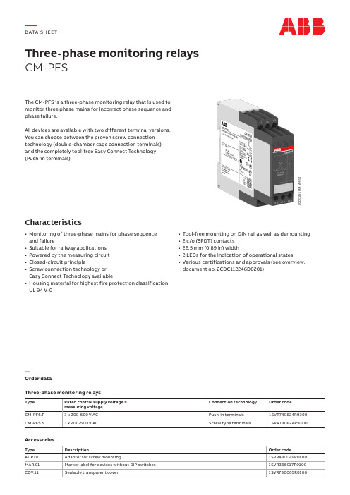
Three-phase monitoring relays CM-PFSThe CM-PFS is a three-phase monitoring relay that is used to monitor three phase mains for incorrect phase sequence and phase failure.All devices are available with two different terminal versions. You can choose between the proven screw connection technology (double-chamber cage connection terminals) and the completely tool-free Easy Connect Technology (Push-in terminals)Characteristics• Monitoring of three-phase mains for phase sequence and failure• Suitable for railway applications • Powered by the measuring circuit • Closed-circuit principle• Screw connection technology or Easy Connect Technology available• Housing material for highest fire protection classification UL 94 V-02C D C 251 014 V 0012• Tool-free mounting on DIN rail as well as demounting • 2 c/o (SPDT) contacts • 22.5 mm (0.89 in) width• 2 LEDs for the indication of operational states• Various certifications and approvals (see overview,document no. 2CDC112246D0201)—Order dataThree-phase monitoring relaysType Rated control supply voltage = measuring voltage Connection technology Order code CM-PFS.P 3 x 200-500 V AC Push-in terminals 1SVR740824R9300CM-PFS.S3 x 200-500 V ACScrew type terminals1SVR730824R9300AccessoriesType DescriptionOrder code ADP.01Adapter for screw mounting1SVR430029R0100MAR.01Marker label for devices without DIP switches 1SVR366017R0100COV.11Sealable transparent cover1SVR730005R0100—DATA S H EE T2DATA SHEET CM-PFSPush-in terminals• Tool-free connection of rigid and flexible wires with wire end ferrule• Easy connection of flexible wires without wire end ferrule by opening the terminals • No retightening necessary• One operation lever for opening both connection terminals • For triggering the lever and disconnecting of wires you can use the same tool (Screwdriver according to DIN ISO 2380-1 Form A 0.8 x 4 mm (0.0315 x 0.157 in), DIN ISO 8764-1 PZ1 ø 4.5 mm (0.177 in))• Constant spring force on terminal point independent of the applied wire type, wire size or ambient conditions (e. g. vibrations or temperature changes)• Opening for testing the electrical contacting • Gas-tightDouble-chamber cage connection terminals • Terminal spaces for different wire sizes• One screw for opening and closing of both cages • Pozidrive screws for pan- or crosshead screwdrivers according to DIN ISO 2380-1 Form A 0.8 x 4 mm(0.0315 x 0.157 in), DIN ISO 8764-1 PZ1 ø 4.5 mm (0.177 in)Both the Easy Connect Technology with push-in terminals and screw connection technology with double-chamber cageconnection terminals have the same connection geometry as well as terminal position.2C D C 253 025 F 00112C D C 253 026 F 0011—Connection technologyMaintenance free Easy Connect Technology with push-in terminalsType designation CM-xxS.yyPApproved screw connection technology with double-chamber cage connection terminals Type designation CM-xxS.yySDATA SHEET CM-PFS3—FunctionsOperating controlsApplicationThe CM-PFS is used to monitor three-phase mains for incorrect phase sequence and phase failure.Operating modeThe three-phase main to be monitored is connected to terminals L1, L2, L3 in accordance to the wiring diagram.The device operates according to the closed-circuit principle g – incorrect phase sequence or phase failure:relays de-energize. The signalling of status indication is made by means of the front-face LEDs.Indication of operational statesR: yellow LED – status indication of the output relays F:red LED – fault messagePhase sequence and phase failure monitoringIf all phases are present with the correct phase sequence, the output relays energize after the start-up delay t s is complete.If a phase failure or a phase sequence error occurs, the output relays de-energize instantaneously.The LED R is on when output relays are energized.In case of motors which continue running with only two phases, the CM-PFS detects phase failure if the reverse fed voltage is less than 60% of the originally applied voltage.21-2221-24L1, L2, L311-1211-14F: red LED R: yellow LEDMeasured valuet s = start-up delay fixed 500 ms2C D C 252 003 F 0212—Electrical connectionL1L22428212522261418L3L3111512161418222624282125L2L1121611151S V C 110 000 F 0118L1, L2, L3Control supply voltage = measuring voltage1115-1216/14182125-2226/2428Output contacts - closed-circuit principle —Connection diagramData at T a = 25 °C and rated values, unless otherwise indicated—Input circuitsType CM-PFSSupply circuit = measuring circuit L1, L2, L3Rated control supply voltage U s = measuring voltage 3 x 200-500 V ACRated control supply voltage U s tolerance-15...+10 %Rated frequency50/60 HzFrequency range45-65 HzTypical current / power consumption400 V AC16 mA / 11 VAMeasuring circuit L1, L2, L3Monitoring functions Phase failure JPhase sequence JMeasuring ranges 3 x 200-500 V ACThreshold value for phase failure U min0.6 x U NHysteresis related to the threshold value-Response time500 msTiming circuitStart-up delay t s fixed 500 ms—User interfaceIndication of operational statesRelay status R1, R2R: yellow LED V output relay energized Fault message F: red LED V Phase failureW Phase sequence error—Output circuitsKind of output11(15)-12(16)/14(18)relay, 1st c/o (SPDT) contact21(25)-22(26)/24(28)relay, 2nd c/o (SPDT) contact1 x2 c/o (SPDT) contacts Operating principle closed-circuit principle 1) Contact material AgNi alloy, Cd freeRated operational voltage U e250 V ACMinimum switching voltage / Minimum switching current24 V / 10 mAMaximum switching voltage / Maximum switching current see "Load limit curves" on page 7Rated operational voltage U e and rated operational current I eAC-12 (resistive) at 230 V 4 A AC-15 (inductive) at 230 V 3 A DC-12 (resistive) at 24 V 4 A DC-13 (inductive) at 24 V 2 AAC rating (UL 508)utilization category(Control Circuit Rating Code)B 300 pilot duty;general purpose 250 V, 4 A, cos phi 0.75 max. rated operational voltage300 V ACmax. continuous thermal current at B 300 5 Amax. making/breaking apparent power at B 3003600/360 VAMechanical lifetime30 x 106 switching cycles Electrical lifetime AC-12, 230 V, 4 A0.1 x 106 switching cyclesMaximum fuse rating to achieve short-circuit protection n/c contact 6 A fast-acting n/o contact10 A fast-actingConventional thermal current I th 4 A1) Closed-circuit principle: output relays de-energize if the measured value exeeds/drops below the threshold.—General dataMTBF on requestDuty cycle100 %Dimensions see ‘Dimensional drawings’Weight Screw connection technology Easy Connect Technology (push-in)net0.128 kg (0.282 lb)0.120 kg (0.265 lb)Mounting DIN rail (IEC/EN 60715), snap-on mounting without any toolMounting position anyMinimum distance to other units vertical / horizontal≥ 10 mm (0.39 in) in case of continuous measuring voltage > 440 V Degree of protection housing IP50terminals IP20—Electrical connection—Environmental dataAmbient temperature ranges operation -25...+60 °Cstorage-40...+85 °Ctransport-40...+85 °CClimatic class IEC/EN 60721-3-33K3Damp heat, cyclic IEC/EN 60068-2-30 6 x 24 h cycle, 55 °C, 95 % RHVibration, sinusoidal IEC/EN 60255-21-1Class 2Shock IEC/EN 60255-21-2Class 2—Isolation dataRated insulation voltage U i input circuit / output circuit600 Voutput circuit 1 / output circuit 2300 VRated impulse withstand voltage U impinput circuit / output circuit 6 kV output circuit 1 / output circuit 2 4 kVBasic insulation input circuit / output circuit600 V ACPollution degree 3Overvoltage category III—Standards / DirectivesStandards IEC/EN 60947-5-1, IEC/EN 60255-27, EN 50178 Low Voltage Directive2014/35/EUEMC Directive2014/30/EURoHS Directive2011/65/EU—Railway application standardsEN 50155, IEC 60571“Railway applications – Electronic equipment used on rolling stock”temperature class T3supply voltage category S1, S2, C1*), C2*)IEC/EN 61373“Railway applications – Rolling stock equipment – Shock and vibration tests”Category 1, Class BEN 45545-2 Railway applications – Fire protection on railway vehicles – part 2:Requirements for fire behavior of materialsHL3and components ISO 4589-2LOI 32.3 %NF X-70-100-1 C.I.T. (T12) 0.45EN ISO 5659-2Ds max (T10.03) 104NF F 16-101: Rolling stock. Fire behaviour. Materials choosingNF F 16-102: Railway rolling stock. Fire behaviour. Materials choosing, applicationfor electric equipmentI2 / F2DIN 5510-2 Preventive fire protection in railway vehicles. Part 2: Fire behaviour andfire side effects of materials and partsfullfilled*) only applicable for devices with DC supply—Electromagnetic compatibilityInterference immunity to IEC/EN 61000-6-2electrostatic discharge IEC/EN 61000-4-2Level 3, 6 kV / 8 kVradiated, radio-frequency,electromagnetic fieldIEC/EN 61000-4-3Level 3, 10 V/m (1 GHz) / 3 V/m (2 GHz) / 1 V/m (2.7 GHz) electrical fast transient / burst IEC/EN 61000-4-4Level 3, 2 kV / 5 kHzsurge IEC/EN 61000-4-5Level 3, 2 kV L-Lconducted disturbances, induced byradio-frequency fieldsIEC/EN 61000-4-6Level 3, 10 Vvoltage dips, short interruptionsand voltage variationsIEC/EN 61000-4-11Class 3harmonics and interharmonics IEC/EN 61000-4-13Class 3Interference emission IEC/EN 61000-6-3high-frequency radiated IEC/CISPR 22, EN 55022Class Bhigh-frequency conducted IEC/CISPR 22, EN 55022Class BLoad limit curves2C D C 252 194 F 0205—AC load (resistive)2C D C 252 193 F 0205—DC load (resistive)2C D C 252 192 F 0205—Derating factor F for inductive AC loadSwitching current [A]S w i t c h i n g c y c l e s2C D C 252 148 F 0206—Contact lifetimein mm and inches2C D C 252 009 F 0011—Accessoriesin mm and inches2C D C 252 010 F 00112C D C 252 008 F 00102C D C 252 186 F 0005—ADP.01 - Adapter for screw mounting—MAR.01 - Marker label —COV.11 - Sealable transparent coverFurther documentationDocument titleDocument type Document number Electronic relays and controls Catalog2CDC 110 004 C02xx CM-PAS, CM-PFS, CM-PSS, CM-PVSInstruction manual1SVC 630 510 M0000You can find the documentation on the internet at /lowvoltage-> Automation, control and protection -> Electronic relays and controls -> Measuring and monitoring relays.CAD system filesYou can find the CAD files for CAD systems at -> Low Voltage Products & Systems -> Control Products -> Electronic Relays and Controls.—We reserve the right to make technical changes or modify the contents of this document without prior notice. With regard to purchase orders, the agreed particulars shall prevail. ABB Ltd. does not accept any responsibility whatsoever for potential errors or possible lack of information in this document.We reserve all rights in this document and in the subject matter and illustrations contained therein. Any reproduction, disclosure to third parties or utilization of its contents – in whole or in parts – is forbidden without prior written consent of ABB Ltd. Copyright© 2020 ABB Ltd.All rights reserved/lowvoltage—ABB STOTZ-KONTAKT GmbH Eppelheimer Strasse 8269123 Heidelberg, Germany2C D C 112192D 0201 R e v . G (01/2020)。
ABB继电器
SA
SA
SA 辅助触头
SA 型号 物料号
SA 单极
SA CA5-10 10069838
SA CA5-01 10069839
SA
SA 双极
SA CA6-11K 82202102
SA CA6-11E 82202101
SA CA6-11M 82202096
SA
SA KH800 110
SA KH800 220
SA KH800 380
SA
SA
SA 直流线圈
SA 型号 线圈电压 V DC
SA AE 型接触器适用
SA ZAE75 24
SA RC5-1/250 82201348
SA RC5-1/440 82201349
SA RC5-2/50 82201354
SA RC5-2/133 82201351
SA RC5-2/250 82201352
SA RC5-2/440 82201353
SA
SA RC-EH300/48 82204309
TA
TA TA450SU60 87101537
TA TA450SU80 87101602
TA TA450SU105 82500500
TA TA450SU140 82500501
TA TA450SU185 82500502
TA TA450SU235 87101536
TA TA450SU310 82500503
TA TA450DU185 82500497
TA TA450DU235 82500498
ABB继电器的分类

对于ABB在此先给大家做一个简单的介绍:ABB主要产品包括控制产品、自动转换开关电器、断路器类产品、开关类产品、线路保护产品、开关插座、智能建筑控制系统、电网质量产品、箱壳类产品和低压配电系统。
ABB由两个历史100多年的国际性企业瑞典的阿西亚公司(ASEA)和瑞士的布朗勃法瑞公司(BBC Brown Boveri) 在1988年合并而成。
两公司分别成立于1883年和1891年。
下面主要为大家带来的是ABB继电器的相关分类,一起来看看吧~1.电磁继电器在输入电路内电流的作用下,由机械部件的相对运动产生预定响应的一种继电器。
它包括直流电磁继电器、交流电磁继电器、磁保持继电器、极化继电器、舌簧继电器,节能功率继电器。
(1)直流电磁继电器:输入电路中的控制电流为直流的电磁继电器。
(2)交流电磁继电器:输入电路中的控制电流为交流的电磁继电器。
(3)磁保持继电器:将磁钢引入磁回路,继电器线圈断电后,继电器的衔铁仍能保持在线圈通电时的状态,具有两个稳定状态。
(4)极化继电器:状态改变取决于输入激励量极性的一种直流继电器。
(5)舌簧继电器:利用密封在管内,具有触点簧片和衔铁磁路双重作用的舌簧的动作来开、闭或转换线路的继电器。
(6)节能功率继电器:输入电路中的控制电流为交流的电磁继电器,但它的电流大(一般30-100A),体积小,节电功能。
2.固态继电器输入、输出功能由电子元件完成而无机械运动部件的一种继电器。
3.时间继电器当加上或除去输入信号时,输出部分需延时或限时到规定的时间才闭合或断开其被控线路的继电器。
4.温度继电器当外界温度达到规定值时而动作的继电器.5.风速继电器当风的速度达到一定值时,被控电路将接通或断开。
6.加速度继电器当运动物体的加速度达到规定值时,被控电路将接通或断开。
7.其它类型的继电器如果您想了解更多有关ABB继电器方面的资讯,推荐您联系南京首科机电咨询详情。
南京首科机电有限公司集生产、贸易、技术、服务于一体的机电专业性公司。
ABB REF615馈线保护继电器 说明书
输入值通常用于需要灵敏接地故障保护和磁势 平衡电流互感器的应用。零序电压输入值包括 额定电压 100、110、115 和 120 V。
通过继电器调试软件(PCM600 或 WebHMI) 修改相关参数可选择相电流输入值 1A 或 5A, 零序电流输入值 1A 或 5A,或 0.2A 或 1A,以 及零序电压输入值。另外,开关量输入门槛值 范围为 18...176V DC,可修改开关量输入参数 在设定范围内进行选择。
过电流、方向 接地保护
标准配置 标准配置
A
B
-
-
-
-
-
-
-
-
过电流、无方向 接地保护
标准配置 标准配置
C
D
-
-
-
-
-
-
-
-
-
-
4
ABB
馈线保护继电器 REF615 产品版本:1.1
1YZA000042
保护功能(续)
断相保护 热过负荷保护 断路器失灵保护 涌流检测 弧光保护 自动重合闸 控制功能 带基本联锁功能的断路器控制 1) 带扩展联锁功能的断路器控制 2) 状态监视 断路器状态监视 跳闸回路监视,可监视 2 个跳闸线圈 测量功能 故障录波 三相电流测量 电流序分量 零序电流测量 零序电压测量
1) 可选
(标准配置 A/B)
跳闸信号至输出馈线
母线上的弧光探测
架空线
(标准配置 A/B) 1) 可选
(标准配置 A/B) 1) 可选
图3:使用带有相关选项的标准配置 A 或 B 的变电站过电流和接地故障保护。在输入馈 线间隔中,未使用的保护功能没有颜色并有虚线轮廓标记。继电器配备的可选的 弧光保护功能可实现对整个开关柜设备的快速且有选择性保护。
ABB继电器选型资料
开关量输入和输出接点数量
输入/输出接点数量 开关量输入接点 跳闸回路监视输出接点
REF 541 15 2
REF 543 25 2
REF 545 34 2
大容量输出接点(NO 单极)
0
大容量输出接点(NO 双极)
5
信号输出接点(NO)
2
2
3
9
11
2
4
信号输出接点(NO/NC)
5
5
8
装置自检输出接点
1
1
0,IEC 60870-5-103 及 SPA 协议,通讯波特率最大可 量量、控制、报警和参数的详细信息。
至 19.2kbps。这些端口可以方便用户简易快速地接入各
类厂家的后台系统。
REF 541,REF 543 和 REF 545 的差别仅仅在于三者的开
关量输入和输出接点数量不同。
4
二 订货号
REF 54_ KC127AAAA
1
5
三 端子接线图
*) 功率方向 **) 典关 Q1 合 隔离开关 Q1 分
隔离开关 Q2 合 隔离开关 Q2 分 隔离开关 Q3 合 隔离开关 Q3 分
REF 542plus 开关柜保护和测控装置
一概述
在中压开关柜的无论有无后台系统各种应用场合中,均能 使用数字式控制技术的解决方案。开关柜保护和测控装置 REF 542plus 就如同它的前一代产品 REF 542,集成了测 量、监视、保护、控制和自检等功能,同时拥有完善的通 讯规约,REF 542plus 能够方便地集成到 ABB 或其他第三 方后台系统中。上述功能和其他一些电能质量检测功能都 基于可编程环境中,新一代装置特别的灵活性和可扩展性 使得一个装置可实现所有的二次方案,甚至传统的方法无 法实现的方案,它都很容易实现。
ABB CR-M 继电器技术参数
Logical socket for 2 c/o Logical socket for 3 c/o Logical socket for 2/4 c/o
Logical socket for 2 c/o Logical socket for 2/4 c/o
Standard socket for 2 c/o Standard socket for 3 c/o Standard socket for 2/4 c/o
Standard socket for 2 c/o Standard socket for 2/4 c/o
screw spring connection screw fork type
Socket accessories
CR-MH CR-MH1
CR-MJ
Plastic holder Metal holder
1SVR 405 613 R9000 1SVR 405 613 R0000 1SVR 405 613 R5000 1SVR 405 613 R7000 1SVR 405 613 R2000 1SVR 405 613 R3000 1SVR 405 611 R4100 1SVR 405 611 R1100 1SVR 405 611 R6100 1SVR 405 611 R4300 1SVR 405 611 R8100 1SVR 405 611 R8300 1SVR 405 611 R9100 1SVR 405 611 R0100 1SVR 405 611 R5100 1SVR 405 611 R7100 1SVR 405 611 R2100 1SVR 405 611 R3100 1SVR 405 612 R4100 1SVR 405 612 R1100 1SVR 405 612 R6100 1SVR 405 612 R4300 1SVR 405 612 R8100 1SVR 405 612 R8300 1SVR 405 612 R9100 1SVR 405 612 R0100 1SVR 405 612 R5100 1SVR 405 612 R7100 1SVR 405 612 R2100 1SVR 405 612 R3100 1SVR 405 613 R4100 1SVR 405 613 R1100 1SVR 405 613 R6100 1SVR 405 613 R4300 1SVR 405 613 R8100 1SVR 405 613 R8300 1SVR 405 613 R9100 1SVR 405 613 R0100 1SVR 405 613 R5100 1SVR 405 613 R7100 1SVR 405 613 R2100 1SVR 405 613 R3100
abb热敏电阻电机保护继电器对应温度

温度是许多电气设备运行过程中需要重点关注的一个参数,特别是在电机运行中。
为了保护电机免受过热或过载的损害,abb热敏电阻电机保护继电器应运而生,成为电机保护的重要设备之一。
1. abb热敏电阻电机保护继电器的工作原理abb热敏电阻电机保护继电器是一种感应电动机温度的装置,它通过监测电动机的热敏电阻来实现电机温度的监测和保护。
当电机温度超出设定的安全范围时,热敏电阻会发生相应的变化,导致abb热敏电阻电机保护继电器触发,切断电机的电源,从而保护电机免受过载或过热的危害。
2. abb热敏电阻电机保护继电器对应温度的设定abb热敏电阻电机保护继电器的对应温度是其工作的关键参数之一。
根据不同型号和规格的电动机,abb热敏电阻电机保护继电器可以设置不同的对应温度,以确保对电机的有效保护。
通常情况下,用户可以根据实际情况,结合电机的额定功率和运行环境,来确定适合的对应温度,从而保证电机在正常运行范围内。
3. abb热敏电阻电机保护继电器的优点和作用abb热敏电阻电机保护继电器具有以下几点优点和重要作用:- 高效保护:abb热敏电阻电机保护继电器可以及时监测电机温度,并在温度超出安全范围时自动切断电源,有效保护电机免受损坏。
- 灵活可调:abb热敏电阻电机保护继电器的对应温度可以根据实际需要进行灵活调整,使其适应不同类型和规格的电动机。
- 安全可靠:abb热敏电阻电机保护继电器采用先进的传感技术和保护原理,确保其在各种恶劣环境和工况下能够稳定可靠地工作。
4. 对于abb热敏电阻电机保护继电器的个人理解作为我个人对abb热敏电阻电机保护继电器的理解,我认为它是电机保护领域中不可或缺的一部分。
在电机运行过程中,由于工作环境、负载变化等原因,电机很容易出现过载或过热的情况,而abb热敏电阻电机保护继电器的出现,有效地解决了这一问题。
通过对电机温度的实时监测和保护,abb热敏电阻电机保护继电器不仅能够保证电机的安全稳定运行,还可以延长电机的使用寿命,降低维护成本。
ABB中间继电器选型
ABB中间继电器选型
工品汇,工业品分销采购平台,与国内外上千家工业品品牌合作,如ABB、施耐德、德力西、欧姆龙、西门子等,10万余种产品,正品保障,为您节省时间和成本,提供专业的MRO采购服务!ABB中间继电器被应用于很多领域,需要的型号也有所不同,工品汇拥有齐全的中间继电器型号和优惠的价格,如果您想采购ABB中间继电器请点击ABB进行采购。
ABB中间继电器
ABB中间继电器:用于继电保护与自动控制系统中,以增加触点的数量及容量。
它用于在控制电路中传递中间信号。
在工业控制线路和现在的家用电器控制线路中,常常会有ABB中间继电器存在,对于不同的控制线路,ABB中间继电器的作用有所不同,其在线路中的作用常见的有以下几种:
1、代替小型接触器
中间继电器的触点具有一定的带负荷能力,当负载容量比较小时,可以用来替代小型接触器使用,比如电动卷闸门和一些小家电的控制。
这样的优点是不仅可以起到控制的目的,而且可以节省空间,使电器的控制部分做得比较精致。
2、增加接点数量。
abb的欠压脱扣器的延时继电器_概述说明

abb的欠压脱扣器的延时继电器概述说明1. 引言1.1 概述本文旨在介绍ABB公司的欠压脱扣器的延时继电器。
欠压脱扣器是一种重要的电气保护装置,用于在电力系统中检测电压异常情况下进行断开操作。
而延时继电器则是为了解决瞬态电压波动带来的误分闸问题而被引入。
1.2 文章结构本文将分为六个部分进行详细说明和讨论。
首先,在引言部分,我们将提出文章的背景和目标,概述ABB公司的欠压脱扣器的延时继电器。
接下来,我们将详细介绍ABB公司的欠压脱扣器及其延时继电器的功能与应用领域。
然后,我们将深入探讨欠压保护原理、延时继电器工作原理以及ABB公司所采用的欠压脱扣器的延时继电器机制解析等内容。
随后,我们将介绍技术参数及性能评估方法,并对ABB公司的产品进行性能评估结果分析。
接下来,我们将通过典型应用案例介绍ABB公司欠压脱扣器的延时继电器在实际应用中的价值,并对未来发展趋势进行预测。
最后,在结论部分,我们将总结回顾本文内容,并提出进一步研究的建议。
1.3 目的本文的目的是通过对ABB公司欠压脱扣器的延时继电器进行详细介绍和分析,帮助读者全面了解该产品的特点、工作原理、技术参数及性能评估结果,并展望其在电力行业中的前景。
通过本文,读者将能够更好地理解并评估该延时继电器在实际应用中的效果,并为相关领域的研究提供参考和启示。
2. abb的欠压脱扣器的延时继电器2.1 欠压脱扣器介绍欠压脱扣器是一种用于保护电力系统免受供电电压降低的装置。
当供电电压下降到设定的欠压临界值以下时,欠压脱扣器会自动切断供电,以防止设备损坏或故障。
2.2 延时继电器功能及应用领域延时继电器是一种能够在满足特定条件后延迟一段时间再进行动作的继电器。
它通常用于需要在某些条件满足一定时间后才能进行操作的场合,如门控系统、照明控制等。
在ABB公司的欠压脱扣器中,延时继电器被应用于保护装置中,以确保设备对供电问题做出正确响应。
延时继电器可以根据实际需求设置延迟时间,在检测到供电下降后延迟一段时间再进行断开操作,避免误动作和不必要的停机。
abb安全继电器ssr10说明书

abb安全继电器ssr10说明书ABB安全继电器SSR10说明书引言ABB安全继电器SSR10是一款高品质的安全继电器,专为电气控制系统中的安全保护设计。
本说明书将详细介绍SSR10的特点、功能、安装和操作步骤,以及注意事项。
一、产品特点1.1 安全可靠:SSR10采用先进的电路设计,确保在各种工作条件下都能提供稳定可靠的安全保护。
1.2 高灵敏度:SSR10具有高灵敏度的触发电路,能够快速检测到电气系统中的异常情况,并及时断开电源,确保人员和设备的安全。
1.3 多功能:SSR10配备了多种保护功能,包括过载保护、过电压保护、欠压保护等,可根据实际需求进行灵活配置。
1.4 节能环保:SSR10采用先进的节能技术,有效降低功耗,减少能源浪费,符合环保要求。
二、产品功能2.1 过载保护:SSR10能够监测电气系统中的电流变化,并在超过设定值时自动切断电源,防止设备过载损坏。
2.2 过电压保护:SSR10具备过电压保护功能,当电压超过设定范围时,能够及时切断电源,保护设备安全。
2.3 欠压保护:SSR10能够检测电气系统中的电压变化,当电压低于设定值时,自动切断电源,避免设备损坏。
2.4 短路保护:SSR10具有短路保护功能,能够快速检测到短路故障,并迅速切断电源,防止火灾等安全事故发生。
三、安装步骤3.1 安装位置选择:在安装SSR10之前,需选择一个合适的位置,确保能够方便触发器与电气系统的连接,并保证设备通风良好。
3.2 连接电路:根据电气系统的需求,将SSR10与触发器和电源进行连接,确保连接牢固可靠。
注意根据接线图正确连接线路,避免接反或短路。
3.3 固定安装:将SSR10固定在安装位置上,确保设备牢固稳定,防止因振动而导致连接不良或损坏。
四、操作步骤4.1 开机检查:在启动电气系统之前,需检查SSR10的连接是否正确,确保设备处于正常工作状态。
4.2 参数设置:根据实际需求,设置SSR10的各项参数,包括触发电流、过载保护值等,确保设备能够以最佳状态工作。
abb热继电器使用说明书
abb热继电器使用说明书ABB热继电器使用说明书一、产品概述ABB热继电器是一种常用的电器控制装置,广泛应用于电力系统、工业自动化等领域。
它通过控制电路中的电流大小,实现对电气设备的保护和控制。
二、产品特点1. 灵敏可靠:ABB热继电器采用先进的技术,具有高灵敏度和可靠性,能够在电路发生故障时迅速切断电源,保护设备安全。
2. 超负荷保护:热继电器可根据设定的电流阈值,实现对电气设备的超负荷保护,避免设备损坏和事故发生。
3. 过载保护:当电器设备长时间运行超负荷时,热继电器能够自动切断电源,防止设备过热,保护设备的寿命。
4. 短路保护:ABB热继电器具有快速短路保护功能,能够在电路发生短路时迅速切断电源,防止设备受损。
5. 低功耗:热继电器在正常工作状态下功耗较低,节能环保。
三、使用方法1. 安装:首先确定要安装热继电器的位置,确保安装地点干燥、通风良好,并远离易燃、易爆物品。
然后按照产品说明书中的示意图,将热继电器固定在安装板上,并正确连接电路。
2. 设置参数:根据实际需求,设置热继电器的动作电流和动作时间。
一般来说,动作电流应根据被保护设备的额定电流来设定,动作时间则根据设备的响应速度和保护要求来确定。
3. 连接电路:根据热继电器的接线图,将电源线、负载线和控制线正确连接到热继电器的对应端子上。
注意确保连接牢固、接触良好,避免接线松动或接触不良导致故障。
4. 调试测试:在安装和连接完成后,进行调试测试以确保热继电器正常工作。
首先检查电路连接是否正确,然后依次进行超负荷、短路等测试,观察热继电器的动作情况是否符合预期。
5. 日常维护:定期检查热继电器的工作状态,确保其正常运行。
如发现异常情况,及时进行维修或更换。
四、注意事项1. 严禁在电源通电的情况下进行热继电器的安装和拆卸。
2. 在调试和测试过程中,应注意安全,避免触电和其他意外事故的发生。
3. 使用热继电器时,应按照额定电流和额定电压范围内使用,避免超负荷和过压现象。
ABB继电器TA25DU4.0M
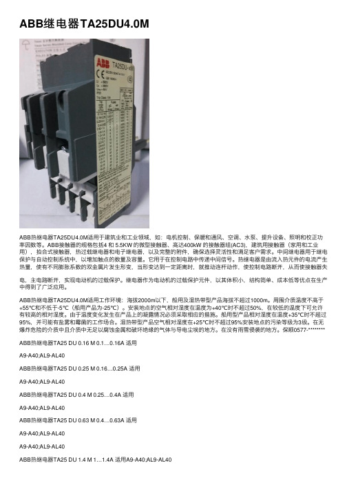
ABB继电器TA25DU4.0MABB热继电器TA25DU4.0M适⽤于建筑业和⼯业领域,如:电机控制、保暖和通风、空调、⽔泵、提升设备、照明和校正功率因数等。
ABB接触器的规格包括4 和 5.5KW 的微型接触器、⾼达400kW 的接触器组(AC3),建筑⽤接触器(家⽤和⼯业⽤),拍合式接触器,热过载继电器和电⼦继电器,以及完整的附件,确保选择灵活性和满⾜客户需求。
中间继电器⽤于继电保护与⾃动控制系统中,以增加触点的数量及容量。
它⽤于在控制电路中传递中间信号。
热继电器是由流⼊热元件的电流产⽣热量,使有不同膨胀系数的双⾦属⽚发⽣形变,当形变达到⼀定距离时,就推动连杆动作,使控制电路断开,从⽽使接触器失电,主电路断开,实现电动机的过载保护。
继电器作为电动机的过载保护元件,以其体积⼩,结构简单、成本低等优点在⽣产中得到了⼴泛应⽤。
ABB热继电器TA25DU4.0M适⽤⼯作环境:海拔2000m以下,船⽤及湿热带型产品海拔不超过1000m。
周围介质温度不⾼于+55℃和不低于-5℃(船⽤产品为-25℃)。
安装地点的空⽓相对湿度在温度为+40℃时不超过50%,在较低的温度下可允许有较⾼的相对湿度。
由于温度变化发⽣在产品上的凝露情况必须采取相应的措施。
船⽤型产品相对湿度在温度+35℃时不超过95%,并可能有盐雾和霉菌的⼯作场合。
湿热带型产品空⽓相对湿度在+25℃时不超过95%安装地点的污染等级为3级。
在⽆爆炸危险的介质中且介质中⽆⾜以腐蚀⾦属和破坏绝缘的⽓体与导电尘埃的地⽅。
在没有⾬雪侵袭的地⽅。
保顺0577-******** ABB热继电器TA25 DU 0.16 M 0.1…0.16A 适⽤A9-A40;AL9-AL40ABB热继电器TA25 DU 0.25 M 0.16…0.25A 适⽤A9-A40;AL9-AL40ABB热继电器TA25 DU 0.4 M 0.25…0.4A 适⽤A9-A40;AL9-AL40ABB热继电器TA25 DU 0.63 M 0.4…0.63A 适⽤A9-A40;AL9-AL40A9-A40;AL9-AL40ABB热继电器TA25 DU 1.4 M 1…1.4A 适⽤A9-A40;AL9-AL40ABB热继电器TA25 DU 1.8 M 1.3…1.8A 适⽤A9-A40;AL9-AL40ABB热继电器TA25 DU 2.4 M 1.7…2.4A 适⽤A9-A40;AL9-AL40ABB热继电器TA25 DU 3.1 M 2.2…3.1A 适⽤A9-A40;AL9-AL40ABB热继电器TA25 DU 4.0 M 2.8…4A 适⽤A9-A40;AL9-AL40ABB热继电器TA25 DU 5.0 M 3.5…5A 适⽤A9-A40;AL9-AL40ABB热继电器TA25 DU 6.5 M 4.5…6.5A 适⽤A9-A40;AL9-AL40ABB热继电器TA25 DU 8.5 M 6…8.5A 适⽤A9-A40;AL9-AL40ABB热继电器TA25 DU 11 M 7.5…11A 适⽤A9-A40;AL9-AL40ABB热继电器TA25 DU 14 M 10…14A 适⽤A9-A40;AL9-AL40A9-A40;AL9-AL40ABB热继电器TA25 DU 25 M 18…25A 适⽤A9-A40;AL9-AL40ABB热继电器TA25 DU 32 M 24…32A 适⽤A9-A40;AL9-AL40ABB热继电器TA42 DU 25 M 18…25A 适⽤A30A40;AL9-AL40ABB热继电器TA42 DU 32 M 22…32A 适⽤A30A40;AL9-AL40ABB热继电器TA42 DU 42 M 29…42A 适⽤A30A40;AL9-AL40ABB热继电器TA75 DU 32 M 22…32A 适⽤A50-A75;AE50-AE75ABB热继电器TA75 DU 42 M 29…42A 适⽤A50-A75;AE50-AE75ABB热继电器TA75 DU 52 M 36…52A 适⽤A50-A75;AE50-AE75ABB热继电器TA75 DU 63 M 45…63A 适⽤A50-A75;AE50-AE75ABB热继电器TA75 DU 80 M 60…80A 适⽤A50-A75;AE50-AE75A95A110;AF95AF110ABB热继电器TA110 DU 110 80…110A 适⽤A95A110;AF95AF110ABB热继电器TA200 DU 110 80…110A 适⽤A145A185 ABB热继电器TA200 DU 135 100…135A 适⽤A145A185 ABB热继电器TA200 DU 150 110…150A 适⽤A145A185 ABB热继电器TA200 DU 175 130…175A 适⽤A145A185 ABB热继电器TA200 DU 200 150…200A 适⽤A145A185 ABB热继电器TA450 DU 185 130…185A 适⽤A210A260A300ABB热继电器TA450 DU 235 165…235A 适⽤A210A260A300ABB热继电器TA450 DU 310 220…310A 适⽤A210A260A300ABB热继电器TA900 DU 375 265…375A 适⽤AF400-750 ABB热继电器TA900 DU 500 355…500A 适⽤AF400-750 ABB热继电器TA900 DU 650 465…650A 适⽤AF400-750 ABB热继电器TA900 DU 850 610…850A 适⽤AF400-750。
ABB RED615线路差动保护继电器 说明书

RED615 v1.1 中文版产品通告我们很高兴地通知大家,线路差动保护继电器 RED615 1.1 中文版正式发布。
RED615 是 ABB 615 产品系列的成员,它是一种分相线路差动保护继电器(智能保护和测控装置),专为电力系统和工业配电网而设计,包括闭环和多电源供电系统。
615 系列继电器是根据 IEC 61850 规约在全新平台上研发和设计的。
这使产品从根本上支持站内设备互操作与水平通讯等特性,而不必通过附加的通讯模块。
RED615 可为配电网络中架空线和馈线提供分相纵联差动保护。
两台 RED615 通过专有通讯信道互联,形成具可选择性保护方案。
该保护常用于环网或多电源供电系统,同样也可用于带有发电机的辐射状电网系统。
标准配置产品新特性该继电器提供两段分相线路差动保护、过电流保护、负序电流保护和断路器失灵保护。
同时还具有自保持和抑制二次谐波涌流的功能。
除了保护功能外,RED615 还提供可远方/就地切换的断路器控制功能。
●两段分相线路纵联差动保护●内嵌 IEC 61850 通讯标准,支持 GOOSE 信息●通过专有通讯信道互联,形成具可选择性保护方案,为未来发展做好准备●故障录波功能得到提高,可采集12个交流量通道和 64 个开关量通道●获得专利的插拔式硬件设计方案,大大缩短日常测试和维修更换时间●唯一的 PCM 600 调试工具可实现继电器定值整定,信号配置和故障录波处理线路差动保护继电器 RED615 目前只提供一个标准配置版本,详情请见下表。
RED615 支持 IEC 61850 通讯规约从而真正实现站内设备间互相通讯,同时也支持流行的工业标准 Modbus 通讯协议。
继电器支持以太网RJ-45接口(100BASE-TX ),玻璃光纤 ST 接口,同时还支持 9 针的 RS-485 接口。
RED615 按照 IEC 61850 规约设计,包括垂直和水平通讯——继电器到继电器间的相互水平通讯(GOOSE )并符合 IEC 61850-8-1 的各项规范。
ABB监测继电器

CM-SRS.M
2
3
4
1
5
6
2CDC 252 266 F0005
DIP 开关位置
2CDC 252 273 F0005
2CDC 252 284 F0005
III 接线图
A1 - A2 B1 / B2 / B3 - C 1115 - 1216 / 1418 2125 - 2226 / 2428
安装与操作指南
控制产品 - 电子产品和继电器 CM 电子测量和监视继电器
2CDC 252 047 F0b09
单相监视器
CM 系列电子测量和监视继电器 注意:本操作指南不包含技术数据和全部应用说明,所 有数据只具有对产品特性进行说明的作用,因此,不具 备法律效应。详细说明请参阅技术样本或联络 ABB 当地 办事处或浏览 ABB 网站()。如有 更改,恕不通知。
所有dip开关均处于off位置iii接线图a1a2供电电压b1监视测量范围2cdc252205f000511151418输出继电器2428输出继电器测量范围b1c330macmsrsm1b2c10100mab3c011b1c0315cmsrsm2b2c15b3c315如果测量电流gt10a相邻侧面必须留有最少10mm空间13cm电子测量和监视继电器单相监视器iv功能图过电流监视不带故障存储a1a2ledledledledledled欠电流监视不带故障存储a1a2ledledledledledledcm电子测量和监视继电器14单相监视器过电流监视带故障存储a1a2ledledledledledled欠电流监视带故障存储a1a2ledledledledledled动作原则根据设定电流监视器cmsrsm可用作单相acdc系统的过电流监视
abb中间继电器的工作原理及作用

abb中间继电器的工作原理及作用
ABB中间继电器是一种重要的电气元件,它的工作原理及作用是:
ABB中间继电器的工作原理是通过金属电路的改变,来改变电路的电流分布,使得电路中的电流按照预定的方式流动。
它的作用是将一个发出的信号转换成另一个信号,从而起到控制和保护电路的作用。
它也可以用于控制电路的自动化,使得电路的操作更加便捷和安全。
ABB中间继电器的优点是它的结构紧凑,小巧,重量轻,可靠性强,抗干扰能力强,反应速度快,寿命长等。
此外,它的安装维护也很方便,可以有效地提高电路的安全性和可靠性。
ABB中间继电器的工作原理及作用是将一个发出的信号转换成另一个信号,从而起到控制和保护电路的作用。
它具有结构紧凑、小巧、重量轻、可靠性强、抗干扰能力强、反应速度快、寿命长等优点,可以有效地提高电路的安全性和可靠性。
ABB REF610馈线保护继电器 说明书

用户指南
2
特点
REF 610 馈 线 保 护 继 电 器
发布:2004.9.22 版本:B2/2006.02.02 本公司保留数据修改权利,恕不另行通知
● 定时限或反时限特性的过电流保护 ● 定时限或瞬时特性的限时电流速断保护 ● 定时限或瞬时特性的电流速断保护 ● 定时限,反时限或瞬时特性的零序电流Ⅱ段
● RI 型反时限曲线特性下
动作值精度 ● 0.3...0.5 × In
● 0.5...5.0 × In ● 5.0...35.0 × In
0.05...1.00 甚反时限 极反时限 次反时限 一般反时限 1...15 50 ms 2) 30 ms 0.05...2.50 s 0.96
50 ms 30 ms
● RI 型反时限曲线特性下 动作值精度 ● 1.0...10.0% In ● 10.0...100% In ● 100...400% In
0.05...1.00 甚反时限 极反时限 次反时限 一般反时限 1...15 50 ms 2) 30 ms 0.05...2.50 s 0.96
50 ms 30 ms
Ur=110/125/220/250 V dc
Ur=24/48/60 V dc
85...110% × Ur (ac)
80...120% × Ur
80...120% × Ur (dc)
<9 W/13 W
最大值:直流电压额定值的 12%
<50 ms,在额定 Uaux 下 <350 ms
+100℃
T2A / 250 V
1.0...100% In 1.0...40% In 1) 60 ms
信号继电器ppt课件

数据采集与处理
信号继电器能够采集工业 设备的运行数据,通过数 据处理和分析,优化生产 过程,提高生产效率。
安全防护
安全监控
在安全防护系统中,信号继电器 用于监控各种安全参数,如温度 、压力、流量等,确保设备和人
员安全。
紧急停车
在紧急情况下,信号继电器能够 迅速切断设备电源,防止事故扩
大,保护人员和设备安全。
故障。
故障处理与预防措施
故障处理
根据故障诊断结果,采取相应的措施修复故障。如更换损坏的部件、修复电路等 。
预防措施
针对常见的故障原因,采取相应的预防措施。如加强日常维护、定期检查和测试 等,以降低故障发生的概率。
05
信号继电器发展趋势与展望
技术创新与产品升级
智能控制技术
采用先进的控制算法和传感器技术,实现信号继电器的智能化控 制,提高其稳定性和可靠性。
节能环保技术
采用高效节能技术和环保材料,降低信号继电器的能耗和环境影响 ,符合绿色环保的发展趋势。
微型化技术
通过改进设计和制造工艺,实现信号继电器的微型化,减小其体积 和重量,方便安装和使用。
应用领域拓展
1 2 3
轨道交通
随着城市轨道交通的快速发展,信号继电器在轨 道交通领域的应用将进一步拓展,为列车的安全 、可靠运行提供保障。
消防系统
在消防系统中,信号继电器用于 控制消防设备的启动和停止,及 时扑灭火灾,保障人员和财产安
全。
03
信号继电器选型与配置
选型原则
适用性原则
选用的信号继电器应能适 应安装环境,如温度、湿 度、机械振动等,并能在 规定条件下正常工作。
可靠性原则
应选用经过严格检测和认 证的、具有高可靠性的信 号继电器。
- 1、下载文档前请自行甄别文档内容的完整性,平台不提供额外的编辑、内容补充、找答案等附加服务。
- 2、"仅部分预览"的文档,不可在线预览部分如存在完整性等问题,可反馈申请退款(可完整预览的文档不适用该条件!)。
- 3、如文档侵犯您的权益,请联系客服反馈,我们会尽快为您处理(人工客服工作时间:9:00-18:30)。
标题:abb信号继电器
一:触器适用于建筑业和工业领域,如:电机控制、保暖和通风、空调、水泵、提升设备、照明和校正功率因数等。
ABB接触器的规格包括4和5.5KW的微型接触器、高达400kW的接触器组(AC3),建筑用接触器(家用和工业用),拍合式接触器,热过载继电器和电子继电器,以及完整的附件,确保选择灵活性和满足客户需求,公司制造工厂位于海西经济区的核心----美丽的鹭岛厦门。
二:ABB断路器可为快速恢复运行条件(防止故障发生),并提供最好的解决方案,同时可提供最优的电气安装保护。
从微型断路器到高分断能力的塑壳/空气断路器
三:小型断路器多级:ABB断路器可为快速恢复运行条件(防止故障发生),并提供最好的解决方案,同时可提供最优的电气安装保护。
从微型断路器到高分断能力的塑壳/空气断路器
四:变频器主要用于控制和调节三相交流异步电机的速度,并以其稳定的性能、丰富的组合功能、高性能的矢量控制技术、低速高转矩输出、良好的动态特性及超强的过载能力,在变频器市场占据
着重要的地位。