CSE-M73安装及测试手册
联想 ThinkPad M7Os Gen 3 M80s Gen 3 M90s Gen 3 用户指南

2. 光盘驱动器活动指示灯* 4. 电源按钮和电源指示灯 6. ThinkCentre® LED 8. 耳麦接口 10. USB 3.2 Gen 1 接口 12. 内置扬声器
© Copyright Lenovo 2022
1
M80s Gen 3 和 M90s Gen 3
1. 光盘驱动器弹出按钮* 3. SD 卡插槽* 5. 存储驱动器活动指示灯* 7. 麦克风接口 9. USB-C(3.2 Gen 2)接口 11. USB 3.2 Gen 2 接口
目录
了解您的 Lenovo 计算机 . . . . . . iii
第 1 章 认识您的计算机 . . . . . . . 1
前视图 . . . . . . . . . . . . . . . . . . 1 后视图 . . . . . . . . . . . . . . . . . . 4 功能部件和规格 . . . . . . . . . . . . . . 6 USB 规格 . . . . . . . . . . . . . . . . . 7
iii
iv M70s Gen 3/M80s Gen 3/M90s Gen 3 用户指南
第 1 章 认识您的计算机
前视图
M70s Gen 3
1. 光盘驱动器弹出按钮* 3. SD 卡插槽* 5. 存储驱动器活动指示灯* 7. 麦克风接口 9. USB-C®(3.2 Gen 1)接口 11. USB 3.2 Gen 2 接口
第 1 章. 认识您的计算机 3
后视图
M70s Gen 3
1. 音频输出接口 3. HDMI™ 输出接口 5. USB 2.0 接口 7. 安全锁插槽 9. PS/2 键盘接口* 11. 挂锁环 13. PCI-Express 卡区域
3.0 CS文稿软件用户安装说明

3.0CS文稿软件用户安装说明By Network Product Department Product Marketing Division May 2008Dayang Technology Development Inc.目录目录 (2)3.0文稿安装调试说明 (3)一、安装3.0文稿软件 (3)二、文稿软件调试 (7)2.1数据库连接设置 (7)2.2配置文稿系统 (8)2.3启动新闻消息服务器 (8)附表1新闻文稿软件数据库对应表.......................... 错误!未定义书签。
3.0文稿安装调试说明一、安装3.0文稿软件在一台已经满足所有硬件和软件配置的计算机中,打开 3.0文稿安装文件夹,双击setup.exe安装程序启动安装过程,系统弹出如下窗口:点击“Next”按钮,系统弹出如下窗口:其中第一个选项是文稿软件的安装,第二个选项是文稿的消息服务器的安装,选择需要安装的部分,点击“Next”按钮,系统弹出安装路径选择,如下图:点击“Browse…”按钮可以修改文稿软件的安装路径,(如无必要请勿修改),点击“Next”按钮系统弹出下图:直接点击“Next”,进入下一窗口:点击“Next”按钮,系统开始安装文稿软件。
安装结束后,系统弹出如下窗口,点击“Finsih”按钮,完成文稿软件安装。
安装成功后,桌面会新增如下两个快捷图标,其中NR-NewsManage是文稿软件,NR-SysManage是文稿系统管理软件。
二、文稿软件调试2.1数据库连接设置点击操作系统的“开始”“所有程序”“DayangNRCS III”“Tools”下的“DYDatabaseSet”项,系统弹出如下界面,在此界面中进行数据库连接设置。
设置完成后点击“确认”按钮。
备注:新闻文稿软件数据库对应表:2.2配置文稿系统点击桌面的“NR-SysManage”快捷方式,进入文稿系统管理软件,界面如下图,在软件左侧树中,按照从上到下的顺序一一配置(使用方法参看《3.0文稿软件系统设置手册》)。
CEM 微波(MARS )与分析处理技术

3. 将排气管放入通风厨。 注意:MARS 的排气量为 5.8 m3/min
MARS 必须连接到能提供足够电流的插座上,选择相应的电源开关。
打印设置
MARS 可以连接 IBM、Epson、Epson Color、Canon color 和 Citizen Color 打印机。 1. 参考打印机手册连接打印机和 MARS。 2. 连接打印机和 AC 电源。 3. 参考“系统设置”设置打印机。
CEM方法 US EPA方法 功率测试方法 QC方法 样品方法
仪器注意事项
仪器设置 设置菜单 系统变量 压力单位 溶剂传感器 ReactiGuard 按键提示音 EST-300 通用压力传感器 风扇控制 TempGuard TempGuard限 冷却时间
3
屏幕保护时间 时间设置 传感器选择 压力传感器 压力传感器清零 温度传感器 打印设置 串口设置 信息 服务信息 传感器信息 系统历史记录 语言
排气系统
MARS 配备排气管来排除腔体内的腐蚀性和有害气体。排气量为 5.8m3/min
12
进/出接口(选 项)
在仪器右边有两个进/出口。用于安装外接选项的压力和温度控制系统。
不要将金属物放入到进/出口中,也不要修改口径设计, 否则会导致严重的微波泄漏造成不可预知的危险。
压力控制系统 ESP-1500plus(压电传感器)是 MARS 压力控制系统,可以实时检测 (选件一) 反应罐中压力状态。压力传感器拆卸方便。
7
安装条件 工具 安装地点
开箱 附件
MARS 应该安装在实验室中靠近通风厨或者其他通风的工作台面上
扳手 手套 防护眼镜 安装地点选择:
提供一处两侧空余 20cm、后部空余 15cm 的实验台,实验台面尺寸 至少 100cm×80cm。
安规综合测试仪使用手册
BenQ M73系列网络投影机使用手册说明书

M73 系列网络投影机操作指南V1.01版权所有版权所有 2018 BenQ Corporation。
保留所有权利。
未经 BenQ Corporation 事先书面许可,不得以任何形式或方式,包括电子、机械、磁性、光学、化学、手写或其它方式,对本文的任何部分进行复制、传输、转译、储存于检索系统或翻译成任何文字或电脑语言。
本手册中提及的所有其它标志、产品或公司名称可能是其各自公司的注册商标或版权,在此仅用于信息目的。
免责声明BenQ Corporation 未对本手册中的任何内容作出任何明示或暗示的陈述或保证,尤其对适销性或针对特定用途的适用性不提供任何保证。
此外,BenQCorporation 保留修订本出版物和随时修改本文档内容而无需通知任何人的权利。
本用户手册旨在为客户提供最新和最准确信息,因此所有的内容都会适时修改而不另行通知。
请访问以获得本手册的最新版本。
BenQ 对于本产品可能链接的由第三方维护和控制的网站内容或类似资源不承担责任。
提供这些网站或类似信息源的链接并不意味着 BenQ 对其内容做出任何明示或默示的保证或陈述。
本产品预安装的任何第三方内容或服务均按“现状”提供。
BenQ 对于第三方提供的内容或服务不做出任何明示或默示的保证。
BenQ 对于第三方所提供内容或服务的正确性、有效性、最新性、合法性或完整性不做出任何保证。
在任何情况下,BenQ 对于第三方提供的内容或服务(包括第三方的疏忽)不承担任何责任。
第三方提供的服务可能暂时或永久性终止。
BenQ 对于第三方提供的任何内容或服务是否随时处于良好状态不做保证或担保,对于此等内容和服务的终止不承担责任。
此外,BenQ 不参与您在第三方维护的网站或类似资源中进行的任何交易。
您有任何问题、疑虑或争议,应联系该内容或服务的提供商。
目录准备 (5)切换到高级 (5)有线连接 (6)为投影机设置有线网络 (6)通过有线连接将电脑连接到投影机 (7)无线连接 (8)为投影机设置无线网络 (8)将电脑或移动设备以无线的方式连接到投影机。
最新中国电信家庭网关设备检测指导手册(ap外置型pon上行e8c(非机卡))_xhh资料

中国电信家庭网关测试要求--A P外置型E P O N/G P O N上行e8-C(非机卡分离)2014年4月目录前言 (2)1测试组网 (3)2IPV6功能 (7)2.1.IP V6基本功能测试 (7)2.2.IP V4/V6双栈功能测试 (13)2.3.IP V6软件升级及业务流程测试 (33)2.4.IP V4/V6双栈性能测试 (40)2.5.MLD功能测试 (46)2.6.DS-L ITE测试 (48)3其它功能 (56)3.1.语音相关 (56)3.2.Q O S功能 (60)3.3.管理及维护 (63)3.4.逻辑ID注册 (79)3.5.安全性测试 (83)3.6.光路接口能力 (87)3.7.稳定性 (89)3.8.中间件功能 (90)3.9.硬件方案及UI (92)3.10.认证及防雷击 (99)3.11.手机APP管理家庭网关功能 (101)前言本测试要求是根据中国电信开展家庭宽带业务的实际需要而制定的,主要包括针对家庭网关的宽带接入、家庭内部联网、业务承载、安全、QoS、管理维护、IPv6、、手机APP操控等功能要求的测试内容、测试方法和测试指标。
本测试要求仅针对AP外置型EPON/GPON上行e8-C(非机卡分离)设备。
本测试要求由中国电信股份有限公司上海研究院根据中国电信集团公司的要求起草。
1测试组网下面各章节所列的测试用例中,家庭网关(e8-c)用到以下网络连接配置方式(图中:B——桥接,R——路由)。
方式一:方式描述:3条VLANVLAN1支持1条路由session,用户上网使用该通道,TR069不可使用本通道VLAN2支持1条路由session,供TR069和VoIP使用,用户上网设备(如PC等)不可通过本通道上网VLAN3支持桥接session,供用户设备(如机顶盒)使用方式二:方式描述:3条VLANVLAN1为桥接模式,支持至少4条session,供用户设备(如PC)拨号上网,且用户设备能够访问家庭网关VLAN2为路由模式,为TR069和VoIP的专用通道,用户上网设备(如PC等)不可通过此通道上网VLAN3支持桥接session,供用户设备(如机顶盒)使用方式三:方式描述:3条VLANVLAN1同时支持4条桥接session和1条路由session,使用以下两种方式之一承载上网业务(TR069不可使用本通道,用户上网设备能够访问家庭网关):⏹4条桥接session供用户上网设备(如PC)IPv6拨号后上网,1条路由session供用户上网设备IPv4上网⏹4条桥接session供用户上网设备(如PC)IPv4拨号后上网,1条路由session供用户上网设备IPv6上网VLAN2为路由模式,为TR069和VoIP的专用通道,用户上网设备(如PC等)不可通过此通道上网VLAN3支持桥接session,供用户设备(如机顶盒)使用方式四:方式描述:4条VLANVLAN1支持1条路由session,用户上网使用该通道,TR069不可使用本通道VLAN2支持1条路由session,供TR069使用,用户上网设备(如PC 等)不可通过本通道上网VLAN3支持1条路由session,供VoIP使用,用户上网设备(如PC等)不可通过本通道上网VLAN4支持桥接session,供用户设备(如机顶盒)使用2IPv6功能2.1.IPv6基本功能测试2.1.1 IPv6地址获取及下发功能一(WAN侧SLAAC、LAN侧SLAAC)2.1.2 IPv6地址获取及下发功能二(WAN侧DHCPv6、LAN侧SLAAC)2.1.3 IPv6地址获取及下发功能三(WAN侧DHCPv6、LAN侧DHCPv6)2.2.IPv4/v6双栈功能测试2.2.1路由模式下IPv4/IPv6双栈上网功能测试2.2.2桥接模式下IPv4/IPv6双栈上网功能测试2.2.3 IPv4路由/IPv6桥接双栈上网功能测试2.2.4 IPv4桥接/IPv6路由双栈上网功能测试2.2.5路由模式下IPv4/IPv6双栈上网及智能电视功能测试2.2.6 IPv4/IPv6路由模式DHCP认证时的WAN连接Option功能测试2.2.7 IPv4/IPv6路由模式下网关安全性测试2.2.8 IPv4/IPv6路由模式下的公网接入用户总数限制2.2.9多WAN连接下的数据隔离要求测试2.3.IPv6软件升级及业务流程测试2.3.1软件整体远程升级功能测试(仅针对采用双Image升级方式的设备)2.3.1软件整体远程升级功能测试2.3.2业务配置流程测试1(IPv4路由上网改IPv4/v6双栈并添加智能电视)2.3.3业务配置流程测试2(IPv4桥接上网改IPv4/v6双栈并添加智能电视)2.4.IPv4/v6双栈性能测试2.4.1 IPv4/IPv6双栈路由上网性能测试(FTP测试,BRAS不限速)2.4.2 IPv4/v6路由上网性能测试(仪表测试,使用综合业务模板1,针对上网80M最低要求)仪表调用如下综合性能测试模板,运行5分钟,记录数据结果:路由上网下行90Mbps数据流(包含IPv4协议的P2P下载、P2P下载、FTP下载和web浏览,IPv6协议的FTP下载和web浏览等数据流)路由上网上行90Mbps数据流(包含IPv4协议的HTTP上传、FTP协议的FTP上传等数据流)2.4.3 IPv4/v6路由上网性能测试(仪表测试,使用综合业务模板2,针对上网120M建议要求)仪表调用如下综合性能测试模板,运行5分钟,记录数据结果:路由上网下行200Mbps数据流(包含IPv4协议的P2P下载、P2P下载、FTP下载和web浏览,IPv6协议的FTP下载和web浏览等数据流)路由上网上行200Mbps数据流(包含IPv4协议的HTTP上传、FTP2.5.MLD功能测试2.5.1路由模式下的MLDv1 PROXY测试2.5.2 路由模式下的MLDv1 SnooPing测试2.6.DS-Lite测试2.6.1 DS-Lite功能测试。
博根MA3模块适配器安装使用手册说明书

Module Adapter Kit Model MA3Installation and Use Manual©2004 Bogen Communications,Inc.All rights reserved.Specifications subject to change without notice.54-2127-01B 0409DescriptionThe MA3 Module Adapter Kit allows Bogen’s latest line of input modules to work with the D-Series line of amplifiers(Models DMA40,DMA80,DMA 160,DMP06,and DPA 160).One MA3 kit can adapt up to 3 modules in a single D-Series amplifier.T wo MA3 kits can be used in the same D-Series amplifier to adapt up to 6 modules.Note:Signal-processing output modules are not compatible with the D-Series line of amplifiers.InstallationMaster AdapterA master adapter must always be installed,but the two slave adapters are optional and may be installed on an as needed basis.1.Connect the power supply to the adapter.Wire tie the power supply cord to the connector if desired.2.Connect the module to the adapter and slide the power supply cord below the module.3.Insert the two screws supplied with the module through the module screw holes and then through the two washers,with the larger washer first and the smaller retaining washer second.Then,insert the module and adapter into the module bay by sliding them along the card guides inside the module bays.Secure them to the chassis using the two screws.A gap between the unit’s back panel and the module will exist to allow the power supply wire to exit.Slave BoardOnce the master module adapter is installed,the slave adapters can be installed if needed.1.Connect the module to the adapter.2.the card guides inside the module bays.the module to secure it to the chassis.module should be flush with the unit’s back panel.Master AdapterSlave Adapter(X2)Power SupplyWire tie the power supply Package Contents•Master Board • 2 Slave Boards •Power Supply •Wire Tie• 2 Washers (large)•2 Washers (small retaining)Limited WarrantyThe MA3 is warranted to be free from defects in material or workmanship for two (2) years from the date of sale to the original purchaser. Any part of the product covered by this warranty that, with normal installation and use, becomes defective will be repaired or replaced by Bogen, at our option, provided the product is shipped insured and prepaid to: Bogen Factory Service Department, 50 Spring Street, Ramsey, NJ 07446, USA. The product will be returned to you freight prepaid. This warranty does not extend to any of our products that have been subjected to abuse, misuse, improper storage, neglect, accident, improper installation or have been modified or repaired or altered in any manner whatsoever, or where the serial number or date code has been removed or defaced. THE FOREGOING LIMITED WARRANTY IS BOGEN’S SOLE AND EXCLUSIVE WARRANTY AND THE PURCHASER’S SOLE AND EXCLUSIVE REMEDY. BOGEN MAKES NO OTHER WARRANTIES OF ANY KIND, EITHER EXPRESS OR IMPLIED, AND ALL IMPLIED WARRANTIES OF MERCHANTABILITY OR FITNESS FOR A PARTICULAR PURPOSE ARE HEREBY DISCLAIMED AND EXCLUDED TO THE MAXIMUM EXTENT ALLOWABLE BY LAW. Bogen's liability arising out of the manufacture, sale or supplying of products or their use or disposition, whether based upon warranty, contract, tort or otherwise, shall be limited to the price of the product. In no event shall Bogen be liable for special, incidental or consequential damages (including, but not limited to, loss of profits, loss of data or loss of use damages) arising out of the manufacture, sale or supplying of products, even if Bogen has been advised of the possibility of such damages or losses. Some States do not allow the exclusion or limitation of incidental or consequen-tial damages, so the above limitation or exclusion may not apply to you. This warranty gives you specific legal rights, and you may also have other rights which vary from State to State.Products that are out of warranty will also be repaired by the Bogen Factory Service Department -- same address as above or call 201-934-8500. The parts and labor involved in these repairs are warranted for 90 days when repaired by the Bogen Factory Service Department. All shipping charges in addition to parts and labor charges will be at the owner's expense. All returns require a Return Authorization number.07/20/200450 Spring Street,Ramsey,NJ 07446,U.S.A.T el.201-934-8500,Fax:201-934-9832,。
PK-93873-10-00-2C 电子产品安装和使用指南说明书
PK-93873-10-00-2CWARNINGS AND CAUTIONS:• T O AVOID FIRE, SHOCK, OR DEATH; TURN OFF POWER AT CIRCUIT BREAKER OR FUSE AND TEST THAT POWER IS OFF BEFORE WIRING!• T o be installed and/or used in accordance with appropriate electrical codes and regulations.• I f you are unsure about any part of these instructions, consult an electrician.• S ensors must be mounted on a vibration free surface.• D o not terminate using data type wire, such as Cat 5/5E.• D o not mount sensors closer than 10 feet to each other.• A ll sensors must be mounted at least 6 feet away from air vents, air handlers, and reflective surfaces (windows/mirrors).NOTES• D o not touch the surface of the lens. Clean outer surface with a damp cloth only.• O perating Temperature: 32˚ to 104˚F (0˚ to 40˚C)• C ompatible with electronic and magnetic ballasts, electronic and magnetic low-voltage transformers, incandescent lamps, and fans.WARNINGS AND CAUTIONS:For Occupancy Sensors installed to control Emergency Lighting Equipment:If this equipment is being used for Emergency Lighting and Power Equipment, please adhere to the following information. This equipment is rated for only 25C if used on Emergency Lighting Equipment. Apply the "Emergency Circuits" label (provided) to the front cover.IMPORTANT SAFEGUARDSWhen using electrical equipment, basic safety precautions should always be followed, including the following:a) R EAD AND FOLLOW ALL SAFETY INSTRUCTIONS.b) DO NOT use outdoors.c) DO NOT mount near gas or electric heaters.d) Equipment should be mounted in locations and at heights where it will not readily be subjected to tampering by unauthorized personnel.e) The use of accessory equipment not recommended by manufacturer may cause an unsafe condition.f) DO NOT use this equipment for other than the intended use.SAVE THESE INSTRUCTIONSAll servicing shall be performed by qualified service personnel. If any Emergency Circuits are fed or controlled from this panel, it must be located electrically where fed from a UPS, generator, or other guaranteed source of power during emergencies and power outage situations.Ultrasonic Ceiling Mounted Line Voltage Occupancy SensorCalifornia Title 20 CompliantNo Minimum Load RequiredINSTALLATION INSTRUCTIONSCATALOG ITEMSCat. No.DescriptionVoltage RangeCurrent ConsumptionCoverage Suggested MountingLocationO2C05-UDW 1-Way Ultrasonic 120-277V , 50/60 Hz 60-30 ma 500 sq. ft.Mount in corner/overdoorway O2C10-UDW 2-Way Ultrasonic 120-277V , 50/60 Hz 60-30 ma 1000 sq. ft.Mount in center of room/area, 8-12 ft height O2C20-UDW2-Way Ultrasonic120-277V , 50/60 Hz60-30 ma2000 sq. ft.Mount in center of room/area, 8-12 ft height120 V 60 Hz8 A, Electronic Ballast 277 V 60 Hz5 A, Electronic Ballast 800 W/VA, Tungsten, Ballast 1200 VA, Ballast 1/4 Hp1/3 HpRating:6A-6AX 250V 720-1440 W/VA120-240 50HzMLIMITED 5 YEAR WARRANTY AND EXCLUSIONSLeviton warrants to the original consumer purchaser and not for the benefit of anyone else that this product at the time of its sale by Leviton is free of defects in materials and workmanship under normal and proper use for five years from the purchase date. Leviton’s only obligation is to correct such defects by repair or replacement, at its option. For details visit or call 1-800-824-3005. This warranty excludes and there is disclaimed liability for labor for removal of this product or reinstallation. This warranty is void if this product is installed improperly or in an improper environment, overloaded, misused, opened, abused, or altered in any manner, or is not used under normal operating conditions or not in accordance with any labels or instructions. There are no other or implied warranties of any kind, including merchantability and fitness for a particular purpose, but if any implied warranty is required by the applicable jurisdiction, the duration of any such implied warranty, including merchantability and fitness for a particular purpose, is limited to five years.Leviton is not liable for incidental, indirect, special, or consequential damages, including without limitation, damage to, or loss of use of, any equipment, lost sales or profits or delay or failure to perform this warranty obligation. The remedies provided herein are the exclusive remedies under this warranty, whether based on contract, tort or otherwise.。
EMCNetworker7.3安装配置手册(全)

Networker软件安装配置手册2008年 2月 12 日Networker 数据备份管理员手册目录一、备份环境描述 ........................................................................................................- 2 -二、软件安装 ...............................................................................................................- 3 -2.1备份服务器软件安装 .......................................................................................- 3 -2.2备份客户端软件安装 (18)2.3应用模块软件安装 (36)三、备份设置 (42)3.1备份设备创建和设置 (42)3.2备份组的创建和设置 (46)3.3备份客户端的创建和设置 (48)3.4备份策略的设置 (53)3.4.1 备份调度时间表(Schdules)的设置.................................................... - 53 -3.4.2Polices 的创建 (56)3.5特殊应用数据备份的设置 (57)3.5.1 Oracle 数据库的备份配置 (57)四、恢复 (62)Networker 数据备份管理员手册一、备份环境描述北京市网通公司后台业务数据的备份环境如下:1、备份服务器设计为Windows Server 平台;主机名:xxx IP :xx.xx.xx.xx2、备份客户端为两台Sun Solaris10 和两台 IBM AIX平台,数据库均为Oracle10.2.0 ,都采用 Oracle 自身的 RAC 做集群,设计Networker Client Pak For UNIX模块、Cluster支持模块及Oracle 数据库在线备份模块,实现异构环境下双机(Cluster)的 Oracle 数据库在线备份。
赛蓝移动办公平台快速配置手册

赛蓝移动办公平台快速配置手册一、设备的接口配置赛蓝移动办公平台SGA1000的接口出厂IP参数如下:ETH0:192.168.0.254ETH1:192.168.1.254Console:波特率38400二、首次配置赛蓝移动办公平台是基于WEB的配置方式,默认管理员端口是4433,管理员账号是admin, 密码是111111, 首次可以通过默认的IP进入管理界面(注意在本机添加0网段或者1网段的IP),设备默认进入方式如下:https://192.168.0.254:4433或https://192.168.1.254:4433三、修改SGA各网口IP以适合用户具体需求,配置网关和DNS信息。
四、网络测试配置好设备网络信息后,在设备内部做网络测试,看是否能ping通外网域名和内网待发布的服务器。
五、如果设备放在防火墙和路由器后面,需在前端防火墙或路由器上做端口转发(如果设备有固定公网IP,则可以省略此步骤),需要映射的端口如下:TCP 443 (用户使用)TCP 4433(后台管理)TCP 自定义(IP隧道使用端口)TCP 自定义(TCP隧道使用端口)如需用到IPSec需转发UDP 500和UDP4500端口。
六、发布手机应用进入设备后台管理页面,打开【应用发布】——【CAB应用】,点击【添加】,填好应用的名称、服务器的IP地址、服务器的WINDOWS账号、密码,如发布一个B/S的程序(OA或web),需在【登录后的工作目录】里面填IE的路径,为C:\Program Files\Internet Explorer,在【登录后启动程序】里面填IE的可执行文件名称,即IEXPLORE.EXE (此处为要发布的OA的URL),如下图:如发布一个C/S的程序(如ERP),需在【登录后的工作目录】里面填ERP 程序的路径,在【登录后启动程序】里面填IE的可执行文件名称,xxx.exe.(此处为要发布的ERP的exe文件),如下图:应用账户选择方式:使用手动绑定账号如选择这一项,表示应用账户可以与iServer上具有远程桌面登录权限的账号,进行手动绑定,拥有相应资源使用权限的特定用户组中的用户可以手动绑定Windows登录账号,需要在CAB用户绑定页面进行相应绑定,此处的SGA设备前台登录用户名、密码和绑定Windows登录账号、密码可以不同。
CSE-M53 M53N-EVB 用户说明书

串口-以太网联网模块测试板CSE-M53/M53N-EVB 用户说明书Version 1.0Sollae Systems Co., Ltd.1概要............................................................................................................................................ - 2 -1.1 概要.......................................................................................................................................................................... - 2 - 1.2 规格.......................................................................................................................................................................... - 3 - 1.3 电路图(Schematic) .............................................................................................................................................. - 4 - 1.4 功能.......................................................................................................................................................................... - 5 -1.4.1详细说明........................................................................................................................................................ - 5 -1.5 大小.......................................................................................................................................................................... - 8 -2技术支持及质保期..................................................................................................................... - 9 -2.1 技术支持................................................................................................................................................................. - 9 - 2.2 保证.......................................................................................................................................................................... - 9 -2.2.1退货................................................................................................................................................................. - 9 -2.2.2无偿A/S ....................................................................................................................................................... - 9 -2.2.3유상A/S ....................................................................................................................................................... - 9 -3注意事项及免责声明.............................................................................................................. - 10 -3.1注意事项.............................................................................................................................................................. - 10 - 3.2免责声明.............................................................................................................................................................. - 10 - 4变更及文献履历...................................................................................................................... - 12 -11.1概要SOLLAE SYSTEMS的CSE-M53/M53N是将串口通信设备通过因特网将其连接的迷你型模块。
联想 ThinkCentre E73s
PN: SP40F55898Printed in China第一版(2014 年 11 月)© Copyright Lenovo 2014.有限权利声明:如果数据或软件依照通用服务管理(GSA)合同提供,其使用、复制或公开受编号为 GS-35F-05925 的合同条款的约束。
For Those Who Do.、Lenovo、Lenovo 徽标、ThinkCentre 和 ThinkCentre 徽标是 Lenovo 在美国和/或其他国家或地区的商标。
Microsoft 和 Windows 是 Microsoft 公司集团的商标。
DisplayPort 是 Video Electronics Standards Association 的商标。
其他公司、产品或服务名称可能是其他公司的商标或者服务标记。
安全、保修和设置指南简要用户须知ThinkCentre E73s/supportLenovo®电子版手册... 为了更绿色的地球!有关详细的产品信息,请参阅电子版《用户指南》,网址为:/UserManuals打开包装*某些机型配备ThinkCentre®计算机*键盘*注:未提供恢复光盘。
而是在硬盘驱动器上的 Lenovo_Recovery 分区中提供恢复出厂安装的文件和应用程序所需的一切内容。
如果决定删除 Lenovo_Recovery 分区,请务必先创建一张恢复光盘。
需要更多信息,请参阅《用户指南》中的恢复信息。
有关打开计算机上提供的电子版《用户指南》的说明,请参阅“访问《用户指南》”。
使用计算机之前,请阅读此文档此文档提供有关 Lenovo 计算机的关键性安全和法律法规信息。
安全信息激光合规性声明警告:装有激光产品(如 CD-ROM、DVD 驱动器、光纤设备或发射器)时,请注意以下情况:∙请勿卸下外盖。
卸下激光产品的外盖可能会导致遭受危险的激光辐射。
设备中没有可维修的部件。
CATCH Power BLUE 3 安装手册说明书

BLUE 3This product must be installed by alicensed electrician. This product must beinstalled according to the AS3000 –Australian Wiring Standards.Danger to life due to high voltage ACAlways ensure all electricity sources areappropriately isolated when installing thispiece of equipment.Inside the package1 x CATCH Communicator1 x CATCH Diverter1 x AC Power cord1 x CAT5 network cable6 x Current TransformersCommunicatorinsideinto a power socket. Do not use power boards of any type. The network must have a DHCP service running for theCATCH DIVERTER InstallationIMPORTANT:•Maximum load allowed to be connected to HW terminal is 7.2kW.•Cable sizing must be chosen based on the AS3000 wiring standard.•The Diverter must be protected from weather and direct contact.The recommended installation location in inside the meter box,behind the metering board.The maximum load that can be connected to the Diverter is 7.2kW, however the maximum power delivered to the load is 5kW.BEFORE YOU BEGIN:•The arrows next to the CT’s in the wiring diagram represent the arrows on the inside of the CT’s.•Matching the CT’s to the correct phase is critically important special care must be taken to ensure this happens.•NEVER disconnect CT’s from diverter while they are wrapped around a current carrying conductor.•If Off Peak is not available leave the Off Peak connection empty.•Multiple wires can be put through the Load/Solar CT, as long as all currents are in the same direction.•Some electrical jurisdictions do not allow switches in the Off Peak circuit, if this is your case then do not connect the off peak circuit.P H A S E RP H A S E TP H A S E SO F F P E A KH O T W A T E RN E U T R A LE A R T HCONNECTING THE POWER CABLES•Ensure cables are sized for a 7.2kW load•Ensure all terminal block screws are screwed in tight, even the ones that are not used.•Phase sequence is not important, you can arbitrarily choose which phase goes to which Phase connection.•Off Peak MUST come from PHASE R .Active ConductorsIMPORTANT:The wire going into the PHASE R terminal must come from the same phase as the wire going into the OFF PEAK terminal block.CONNECTING THE CURRENT TRANSFORMERSIt is vitally important the CT’s areconnected to the correct Phase.Example:If the BLUE phase is connected to thePHASE S terminal block then the S–Mainsand S-Load ct’s must be connected to theBLUE phase.The instructions below refer to the Phase-S ct’s; however the same holds true for Phase-R and Phase-T.S-MainsOR。
SPARC M7 系列服务器产品说明书

Intel 和 Intel Xeon 是 Intel Corporation 的商标或注册商标。所有 SPARC 商标均是 SPARC International, Inc 的商标或注册商标,并应按照许可证的规定使用。AMD、 Opteron、AMD 徽标以及 AMD Opteron 徽标是 Advanced Micro Devices 的商标或注册商标。UNIX 是 The Open Group 的注册商标。
文档可访问性
有关 Oracle 对可访问性的承诺,请访问 Oracle Accessibility Program 网站 /pls/topic/lookup?ctx=acc&id=docacc。
获得 Oracle 支持
购买了支持服务的 Oracle 客户可通过 My Oracle Support 获得电子支持。有关信息,请访问 /pls/topic/lookup?ctx=acc&id=info;如果您 听力受损,请访问 /pls/topic/lookup?ctx=acc&id=trs。
SPARC M7 系列服务器产品说明
文件号码 E63771-063771-04
版权所有 © 2015, 2017, Oracle 和/或其附属公司。保留所有权利。
本软件和相关文档是根据许可证协议提供的,该许可证协议中规定了关于使用和公开本软件和相关文档的各种限制,并受知识产权法的保护。除非在许可证协议中明 确许可或适用法律明确授权,否则不得以任何形式、任何方式使用、拷贝、复制、翻译、广播、修改、授权、传播、分发、展示、执行、发布或显示本软件和相关文 档的任何部分。除非法律要求实现互操作,否则严禁对本软件进行逆向工程设计、反汇编或反编译。
abb工业机器人集成视觉应用手册(中文)

应用手册Integrated VisionTrace back information: Workspace R15-2 version a20 Checked in 2015-10-22 Skribenta version 4.6.176应用手册Integrated VisionRobotWare 6.02文档编号: 3HAC044251-010修订: E ©版权所有 2013-2015 ABB。
保留所有权利。
本手册中包含的信息如有变更,恕不另行通知,且不应视为 ABB 的承诺。
ABB 对本手册中可能出现的错误概不负责。
除本手册中有明确陈述之外,本手册中的任何内容不应解释为 ABB 对个人损失、财产损坏或具体适用性等做出的任何担保或保证。
ABB 对因使用本手册及其中所述产品而引起的意外或间接伤害概不负责。
未经 ABB 的书面许可,不得再生或复制本手册和其中的任何部件。
可从 ABB 处获取此手册的额外复印件。
本出版物的原始语言为英语。
所有其他语言版本均翻译自英语版本。
©版权所有 2013-2015 ABB。
保留所有权利。
ABB ABRobotics ProductsSe-721 68 Västerås瑞典专业资料目表目表手册概述 .............................................................................................................................................产品文档,IRC5 (7)9 安全 ................................................................................................................................................... 11 1 Integrated Vision 简介 13 1.1 系统概述 .......................................................................................................... 1.2 图像安全 .......................................................................................................... 1.3 Integrated Vision 入门 ........................................................................................ 1.4 术语表 ............................................................................................................. 13 14 15 16 2 3 安装 17 2.1 安装硬件 .......................................................................................................... 2.2 安装软件 .......................................................................................................... 17 19 RobotStudio 用户界面 21 3.1 主窗口 ............................................................................................................. 3.2 在线帮助 .......................................................................................................... 3.3 菜单条 ............................................................................................................. 3.4 控制器浏览器 .................................................................................................... 3.5 图像采集和配置区域 ........................................................................................... 3.6 胶卷 ................................................................................................................ 3.7 调色板窗口 ....................................................................................................... 3.8 上下文窗口 ....................................................................................................... 3.9 Options (选项)对话框 ....................................................................................... 3.10 电子表格视图 .................................................................................................... 21 22 23 26 27 29 30 31 32 33 4 5 FlexPendant 用户界面 37 4.1 RobotWare Integrated Vision ............................................................................... 4.2 操作员视图 ....................................................................................................... 37 38 配置 Integrated Vision 41 5.1 建议的工作步骤 ................................................................................................. 5.2 准备工作 .......................................................................................................... 5.3 设置摄像头 ....................................................................................................... 5.3.1 基本步骤 ................................................................................................ 5.3.2 其它摄像头配置 ....................................................................................... 5.3.3 限制用户访问 .......................................................................................... 5.4 设置新图像作业 ................................................................................................. 5.5 设置图像 .......................................................................................................... 5.6 校准 ................................................................................................................ 5.7 添加图像工具 .................................................................................................... 5.8 输出到 RAPID ................................................................................................... 5.9 I/O 处理 ........................................................................................................... 5.10 准备 RAPID 程序 ............................................................................................... 5.10.1 RobotStudio 中的 RAPID 代码片段 .............................................................. 5.10.2 基本编程示41 42 43 43 45 49 53 54 55 58 60 64 65 65 66 68 70 6 参考信息 71 6.1 坐标系统之间的关系 ........................................................................................... 6.2 校准理论 .......................................................................................................... 6.3 最佳做法 ................................................................................................71 74 76 6.3.1 在采用解决方案前先评估性能 ...................................................................... 76 6.3.2 如何安装摄像头 (77)专业资料目表6.3.3 获取精度 ................................................................................................ 6.3.4 获取良好的照明 ....................................................................................... 6.3.5 图像作业的结构组织 ................................................................................. 6.3.6 启动程序 ................................................................................................ 6.3.7 运行时间内启用和禁用图像工具 . (78)79 80 81 82 6.3.8 避免超出摄像头的存储空间 ......................................................................... 84 6.3.9 备份摄像头到控制器 ................................................................................. 6.3.10 将不同类型的项目分类 .............................................................................. 6.3.11 寻找同一类型的多个项目 ........................................................................... 6.3.12 总是检查确认图像目标在预期限制内 ............................................................. 85 86 88 90 7 RAPID 参考信息 91 7.1 指令: ............................................................................................................. 7.1.1 CamFlush - 从摄像头删除集合数据 .............................................................. 7.1.2 CamGetParameter - 获取不同名称的摄像头参数 ............................................. 7.1.3 CamGetResult - 从集合获取摄像头目标 ........................................................ 7.1.4 CamLoadJob -加载摄像头任务到摄像头 ........................................................ 91 91 92 94 96 7.1.5 CamReqImage - 命令摄像头采集图像 ........................................................... 98 7.1.6 CamSetExposure - 设置具体摄像头的数据 ...................................................100 7.1.7 CamSetParameter - 设置不同名称的摄像头参数 ............................................. 102 7.1.8 CamSetProgramMode - 命令摄像头进入编程模式 ...........................................1047.1.9 CamSetRunMode - 命令摄像头进入运行模式 (105)7.1.10 CamStartLoadJob - 开始加载摄像头任务到摄像头 (106)7.1.11 CamWaitLoadJob – 等待摄像头任务加载完毕 (108)7.2 函数 (109)7.2.1 CamGetExposure - 获取具体摄像头的数据 (109)7.2.2 CamGetLoadedJob - 获取所加载摄像头任务的名称 (111)7.2.3 CamGetName - 获取所使用摄像头的名称 (112)7.2.4 CamNumberOfResults - 获取可用结果的数量 (113)7.3 数据类型 (115)7.3.1 cameradev - 摄像头设备 (115)7.3.2 cameratarget - 摄像头数据 ......................................................................... 116 索引 119专业资料手册概述手册概述关于本手册本手册包含选件 Integrated Vision 安装、配置和日常操作的说明。
CSW-H80基本安装及测试手册
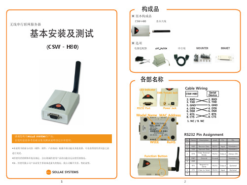
RS232 Pin Assignment
No. 1 2 3 4 5 6 7 Name RXD TXD DTR GND DSR RTS CTS Description Receive Data Transmit Data Data Terminal Ready Ground Request to Send Clear to Send Level RS232 RS232 RS232 Ground RS232 RS232 Dir. Input Output Output Output Input Etc. Mandatory Mandatory Always ON Mandatory Optional Optional -
配置按钮2阶段(TXD LED 闪)
TXD RXD LINK STS Parity
No parity Even Odd No parity Even Odd
Flow Control
No parity Even Odd RTS/CTS RTS/CTS RTS/CTS
1,将两个CSW-H80通过串行线连接 2,分别连接两个电源。 3,分别短按CSW-H80的功能按钮,将其启动为串行设定模式。 4,把其设定为自动后等待,其完成按1:1通信。 LINK LED亮,STS LED亮后将完成正常的TCP连接。 5,将串行电线分离后将其连接在使用者设备上并使用。
打开COM端口
实行随附CD中包括的ezManager后,在[串行栏]中,请 按与产品连接的COM端口中的[打开]按钮。
④ 完成设定后将参数值保存在产品中。 ⑤ 按[保存]按钮保存参数值。保存后按[重启]后点击[关闭]按钮。 ⑥ 重启后将试图与设定的无线网络(SSID)连接。完成无线网络的连接LINK灯亮。 ⑦如LINK灯不亮,请重新确认有关无线网络的设定(WLANMODE,SSID,保安协议)或确认与无 线网络(AP或是AD-HOC设备)的通信距离。(基本天线:室内:20~30M,室外:100~200M,根 据环境不同。)
静电控制 SCS-740 腕带和鞋子测试器安装、操作和维护指南说明书

740EFigure 1. Wrist Strap and Footwear Tester. DescriptionThe SCS 740 Wrist Strap and Footwear Testermeets ANSI/ESD S20.20 per ESD TR53 Compliance Verification testing of personnel grounding devices. The SCS 740 Wrist Strap and Footwear Testers are electronic test instruments that are easy to operate and designed to be wall-mounted. An AC/DC transformer is supplied. The Wrist Strap and Footwear Tester switches off automatically after non-use for approximately 30 minutes.The unit consists of two measurement circuits with an open circuit test voltage of 14V for wrist strap and shoe test applications. For wrist strap and footwear testing, a minimum threshold resistance of 750 kilohm is set internally. The desired maximum allowable resistance level can be selected separately for each measurement. If the resistance of the tested wrist strap or footwearis within the selected range, the green “o.k.”- LED will illuminate. The red “>” - LED alerts the operator that the resistance of the tested device is under 750 kilohm. The red “>”- LED indicates that the selected maximum resistance is exceeded.The Wrist Strap and Footwear Tester can be connectedLED fortoo highresistanceContact platefor shoe testConnectionto AC/DCTransformerSocket for shoeelectrodeUppper limitselection for testOutput signal forexternal devicesGround socketSocket forWrist StrapContact platefor WristStrap TestGround cord4 mm studLED fortoo lowresistanceFigure 2. Wrist Strap and Footwear Tester features and components.SCS offers the following accessories for the Wrist Strap and Footwear Tester:Item Description741Single Foot Plate, for 740 Tester741D Dual Foot Plate, for 740E Tester741DC Foot Plate Cable, for 741D Foot Plate740P Power Adapter, North America Plug740E-X Power Adapter, Europe Plug Packaging1 Wrist Strap and Footwear Tester1 Wall Mounting Kit (Dual Lock Fastening System) 1 Power AdapterInstallationConnecting the 741 and 741D Stainless Steel Foot Plates1. Connect the enclosed cord with the snap fastenerend to the stud of the electrode.2. Connect the plug to the appropriate socket of the740/740E Wrist Strap and Footwear Tester.3. Switch the 740/740E unit on. Continue with WristStrap and Footwear operating instructions.The foot plate must be connected if footwear testing is The enclosed Dual Lock Fastening Discs must be with both hands.Figure 3. Using the Dual Lock Fastening Discs for mounting.Wrist Strap TestPut the wristband on with ground cord attached and insert the ground cord into the wrist strap plug-in jack. Depress the metal contact plate and hold it. One of the indicator-LEDs will illuminate.Wrist Strap and Footwear TesterTemplate5 ft.(1.5 m)If the red “> “- LED is lit, replace the In some cases, high contact resistance between the skin and wristband will cause the tester to show a red “>” - LED condition. This resistance may be caused by dry skin or the presence of hair in the wrist area. The use of a skin lotion is recommended to solve this problem.If a red “>”- LED condition still exists, replace the wristband. Or the presence of hair in the wrist area.Output Connector+5VPin 1, 2 4, or 5ComputerInputComputer Ground Pin 35 kilohm Pin 6Figure 4. Output connection for use with a computer.Pin 1, 2, 4 or 5I max. 20 mARelay Pin 6External voltage source max. 30 VOutput ConnectorFigure 5. Output connection for use with a controlling device.Figure 6. Data output chartThe sequence for testing must be wrist strap test first and then the shoe test.Shaded pin indicators will read “hi” if the sequence is reversed or only the shoe tests are performed.Data Output Connector pin 1, 2, 4, 5 - high or low pin 3 - + 5 V pin 6 - DC-return740E。
创远三模扫频仪操作注意事项

1 创远扫频仪相关介绍本部分主要是这对ASPS所需数据通过上海创远Eagle扫频仪获取时,对应扫频仪如何正常设置、安装以及对应测试模式的设置,文件的导出。
适用于Eagle扫频仪TDD-LTE单模与多模系列产品。
上海创远用于路测数据采集的软件称为“Eagle无线环境评估分析系统”。
在本手册中,我们主要是借用“Eagle无线环境评估分析系统”前台数据采集部分,来说明Eagle扫频仪如何使用。
本手册以下章节中如无特别说明,所述内容均适用于全系列Eagle扫频仪产品。
1.1 支撑型号支持ASPS所需的TOPN测试机制的及相应文件输出的创远扫频仪的型号如下:不同型号的扫频仪上报能力上存在较大差异。
1.2 测量所需设备需要准备的设备与备附件:1、笔记本电脑2、Eagle 扫频仪3、Eagle无线环境评估分析系统软件4、扫频仪4G射频接收天线和GPS天线5、数据线(网线)6、扫频仪AC/DC电源适配器1.3 测量前准备工作1、将TDD-LTE射频天线连接到扫频仪前面板的RF2端口(RF1是为其他制式预留的)。
2、连接GPS天线到GPS端,将天线置于车顶。
3、接通设备电源,按扫频仪面板的power 开关。
4、LAN口处的指示灯红色闪烁表示扫频仪供电正常,连接网线端口数据线至电脑网口,配置电脑IP地址(T2311A型号射频模块默认对应IP地址192.168.0.40;T2311A+型号射频模块默认对应IP地址192.168.1.40请注意,PC端本地连接IP地址设置勿与扫频仪地址相同,否则会由于IP地址冲突无法连接设备。
如有冲突,请及时更改本地连接IP地址,建议设置为与默认地址不冲突的其他IP地址,如192.168.0.111;192.168.1.111,子网掩码默认255.255.255.0 即可。
)5、指示灯变成绿色闪烁,扫频仪处于开工状态。
6、在测试电脑上完成Eagle无线环境评估分析系统软件安装。
1.4 软件的安装及配置1.4.1 系统需求为了使系统可靠运转,保证系统的性能要求,安装时务必保证系统具有以下配置。
- 1、下载文档前请自行甄别文档内容的完整性,平台不提供额外的编辑、内容补充、找答案等附加服务。
- 2、"仅部分预览"的文档,不可在线预览部分如存在完整性等问题,可反馈申请退款(可完整预览的文档不适用该条件!)。
- 3、如文档侵犯您的权益,请联系客服反馈,我们会尽快为您处理(人工客服工作时间:9:00-18:30)。
STATUS/TX TTL LINK/RX
符合RoHS标识及WEEE 标识
SOLLAE SYSTEMS
1
2
基本连接
连接电源
设定产品参数
利用ezManager的参数设定
为了设定CSE-M73使用综合管理实用程序ezManager。 ① 参考基本连接,连接PC与CSE-M73。 ② 实行随附CD里的ezManager。 (在www.sollae.co.kr可下载最新版本。)
构成品
嵌入式串行联网模块
CSE-M73
基本安装及测试
(CSE - M73)
各部名称
RS422/RS485 RS232 ISP 产品型号及MAC地址
感谢您购买SOLLAE SYSTEMS的产品。 在使用前请参考基础安装及测试说明设定后再使用。
-本说明书的部分内容(硬件;软件;产品构成)根据升级功能及其他需要,可在获得使用者同意之前 进行变更。 -因使用者的网络环境及规定,会出现制约使用产品的功能及无法使用的情况。 -如,因使用我公司产品而发生事故或是损失的情况,我公司概不负责,特此说明。
7
8
4. 确认LED 状态
颜色 LED 状态 1秒闪1回 黄色 1秒闪4回 亮 亮 说明 IP地址为固定IP或被分配流动IP时 未被分配流动IP时 TCP 连接中 连接到网络时 没有连接到网络时 网络上有数据时 进入ISP模式时 进入串行设定模式时
2. 通信不好使
- 请重新确认下产品基本安装。 - 请确认是否能接收PING应答。(8页 5. 请参考PING测试) - 请确认当前连服务器模式的情况在[选项]栏可设定只允许特定IP连接。 请核实选项中[产品连接制约]的设定。 - 请核实向ezTCP发送的串行数据大小与实际串行数据进行比较。(8 页 4. 请参考当前状态) - 请核实动作模式。 产品按ISP模式或按串行设定模式工作时无法进行TCP连接。 - 请核实通信模式。 为了完成TCP连接必须一端为服务器,另一端为客户端。两个都为服务器或都为客户端时将 无法进行连接。
故障时注意事项
- 确认TCP连接信息 [ESTABLISHED 10.1.0.2:端口号码] : 与10.1.0.2的HOST与TCP连接状态 [LISTEN 1470]: TCP服务器模式时等待客户端的连接 [SYN_SENT 10.1.0.2:1470]: TCP客户端模式下向10.1.0.2的端口1470连接中 - sio_rx / net_tx / net_rx / sio_tx sio_rx: 加电后向自串行端口接收数据的字节数 net_tx: 自串行端口接收的数据向TCP/UDP数据字节数 net_rx: 自TCP/UDP接收的数据字节数 sio_tx: 自TCP/UDP接收的数据向串行端口传送的数据字节数
③ TCP 连接 在[通信地址]输入“10.1.0.1”[通信端口]输入“1470”后按[连接]按钮。 ② 请选择与CSE-M73连接的网络适配器。 ③ 如上所示,在PC上IP输入10.1.0.2,子网掩码输入255.0.0.0。 ④ 按添加按钮。 ⑤ 在网络适配器增加的IP地址上确认是否已增加。 ※ 注意PC的网络适配器设定为自动接收IP地址的情况,也可能不显示在画面上。 因为不是错误请继续进行。 以上完成了基本安装及测试。CSE-M73的参数值请按实际需适应的网络及串行设备进行 设定。 ④ 选择CSE-M73通过与串行电线连接的PC的相应COM端口后按[打开]按钮。 ⑤ 发送数据 ⓐ(在LAN发送数据)按[发送数据]按钮时ⓓ(串行 接收数据)中显示数据,ⓒ(串行 发送数据)中按[发送数据]按钮时,请在ⓑ(LAN 接收数据)中是否接收数据。
绿色
灭 闪
黄/绿色 黄/绿色
灭 同时闪
5. PING 测试
① 请点击ezManager画面的查看高级按钮后点击[PING/ARP] 按钮。 ② 请在HOST地址输入CSE-M73的IP地址。(基本出厂IP : 10.1.0.1) ③ 点击[查看ARP注册表]按钮。此时CSE-M73的MAC 地址与设定的IP值不同,会有使用相 同IP的HOST。此种情况因发生IP冲突而不能正常使用,请重新设定 CSE-M73的IP。 ④ 点击[删除 ARP]后进行PING测试,确认是否正常工作。
솔내시스템(주) SOLLAE SYSTEMS
公司 研究所 电话 销售咨询 607 Incheon IT Tower 592-5 Dohwa1Dong NamGu Incheon 402-711 605 Incheon IT Tower 592-5 Dohwa1Dong NamGu Incheon 402-711 032.245.2323 / 传真 032.245.2327 sales@sollae.co.kr / 技术咨询 : support@sollae.co.kr
※ 其他咨询项请参考公司网站(www.sollae.co.kr)及博客。
3. 在ezManager查看当前状态
- 点击ezManager的[查看当前状态]按钮 - 确认 IP Address/Subnet Mask/Gateway 状态 固定IP的情况,请确认是否为有效地址;流动IP的情况请确认是否准确的接收了IP地址。
3
4
产品测试
1. 初始化产品
CSE-M73出厂时基本IP是10.1.0.1, 子网掩码是255.0.0.0。 通过ezManager搜索,如参数与上面值不一样,请初始化该值为后进行。 初始化方法如下。 ① 实行ezManager程序后按[全部搜索]按钮。 ② 选择需要初始化的MAC地址后,请选择左下脚的[显示高级按钮]。 ③ 按下方[参数初始化]按钮初始化该产品。
利用VCC, GND针连接电源。
确认LED状态
请确认黄色STATUS LED是否按1秒间隔闪。
连接PC与串行线
将RS232端口与PC的COM端口连接。
连接PC与LAN线
通过LAN线与产品连接,LINK LED为绿色表示正常。
ezManager 实行画面 ③ 按[全部搜索]按钮搜索在同一局域网内的CSE-M73。 ④ 完成搜索,在搜索结果显示CSE-M73的MAC地址。 [网络] [选项] [串行端口] 产品IP地址,子网掩码,网关IP地址 等 是否使用TELNET, 允许远程管理, 制约ezTCP连接限制 等 串行端口设定, 动作模式(TCP动作, UDP) 等 在各栏设定的项目 ⑤ 在各设定栏输入符合安装环境的参数。 ⑥ 完成设定后按[保存]按钮,CSE-M73将自动重启后按设定的参数工作。 ⑦ 按[全部搜索]也无法搜索到时,请确认防火墙是否已解除,没有解除防火墙时,请先解 除防火墙。此时个人防火墙也请一起解除。(V3, Norton 等)
产品测试
3. 通信测试
通过出厂设定参数值在PC上简单进行数据送收测试。 ① 请参考3页基本连接将产品与PC连接。 ② 确认LED动作状态后按ezManager右下端的[通信测试]按钮实行测试程序。
2. 为了产品通信测试在PC添加IP
在PC上添加或设定同一局域网的IP地址10.1.0.2后,进行一下简单的数据送收测试。 ① 请实行随CD附的IP Manager 程序。 (在CD的Utilities文件夹。也可在www.sollae.co.kr下载最新版本。)
5
6
故障时注意事项
1. 通过ezManager无法搜索
- 请确认是否使用正常的程序。 CSE-M73使用的程序是ezManager。 - 请确认Windows的个人防火墙是否在使用中。 如正在使用防火墙,请解除后再搜索。 ※ 按ezManager的高级按钮[Windows防火墙设定]解除防火墙。 - 按ISP模式开始后请进行全部搜索。 [选项]栏中被设定连接制约选项时,无法搜索。 连接 ISP跳线将按ISP模式动作。丢失ezTCP密码时按ISP模式工作可重新设定密码。 按ISP模式工作时,LED状态为只亮电源LED(红色)。 - 无法搜索到IP地址时 在ezManager的[IP 地址]栏输入IP后按读取按钮,将搜索已设定IP的ezTCP。如无法进行 搜索,请将上面事项先检查后,核对下项目时。 ① PING 测试(请参考8 Page 5. PING 测试) ② IP地址搜索使用UDP 50005号端口。部分网络中此端口有可能被禁用,请咨询相应管 理员。