陶氏脱盐型纳滤膜的拆卸更换步骤
陶氏纳滤膜

陶氏纳滤膜简介陶氏纳滤膜(Dow Nanofilration Membrane)是一种高效、可靠的膜分离技术,由美国陶氏化学公司研发并广泛应用于水处理、食品饮料、生物医药等领域。
该膜具有良好的分离性能、高通量、耐腐蚀等特点,成为许多行业中的首选膜材料之一。
分类陶氏纳滤膜根据不同的应用场景和分离要求,可以分为以下几类:1.陶氏NF90纳滤膜2.陶氏NF270纳滤膜3.陶氏NF200纳滤膜这些纳滤膜具有不同的截留分子量范围和分离效率,在不同的领域中都有广泛的应用。
应用领域1. 水处理陶氏纳滤膜在水处理中扮演着重要的角色。
它可以用于海水淡化、废水处理、饮用水净化等方面。
其过滤介质可以有效地去除水中的悬浮物、微生物、大分子有机物等杂质,提供高质量的水源。
2. 食品饮料在食品饮料行业,陶氏纳滤膜被广泛应用于浓缩、纯化、澄清等工艺过程中。
例如,它可以用于乳制品的浓缩、果汁的去浑浊、啤酒的萃取等。
纳滤膜的选择取决于所需的分离效果和生产要求。
3. 生物医药陶氏纳滤膜在生物医药领域有着重要的应用。
它可以用于生物制药中的浓缩、纯化、分离等工艺步骤。
在药物制备过程中,纳滤膜可以去除杂质、提高产品纯度,从而确保药物的质量和安全性。
4. 化工行业在化工行业,陶氏纳滤膜可应用于溶剂回收、废水处理、反应产物分离等方面。
其卓越的分离效果和高通量能够大幅提升生产效率,并减少废物排放。
特点1.高分离性能:陶氏纳滤膜具有独特的膜结构,能够高效地截留微小分子,提供高纯度的分离物。
2.高通量:该膜拥有大的通量,能够快速而高效地进行分离过程,提高生产效率。
3.耐腐蚀性:陶氏纳滤膜由耐腐蚀材料制成,可以在各种恶劣环境下稳定运行。
4.长寿命:经过优化的膜结构和材料选择,使得陶氏纳滤膜具有较长的使用寿命。
使用与维护1.安装时需要注意避免膜材料的损坏和污染,保证正常的运行效果。
2.定期清洗和保养膜组件,以确保其正常的通量和分离性能。
3.避免接触膜组件的硬物体,以免划伤膜表面。
陶氏反渗透和纳滤膜元件产品与技术手册
陶氏反渗透和纳滤膜元件产品与技术手册标题:深度探讨陶氏反渗透和纳滤膜元件产品与技术手册一、引言陶氏反渗透和纳滤膜元件产品与技术手册是当今水处理技术领域备受瞩目的重要文献之一。
我们将在本文中深入剖析该手册的内容,从而全面理解其中蕴含的知识和技术。
二、产品介绍1. 反渗透膜元件我们将从反渗透膜元件的原理、结构和应用展开讨论。
反渗透膜元件作为水处理领域的核心产品,其高效的物质分离功能和广泛的应用前景备受瞩目。
在手册中,对反渗透膜元件的技术参数、使用注意事项和维护保养进行了详细的介绍,使读者能够全面了解其在实际应用中的优势和特点。
2. 纳滤膜元件我们将重点讨论纳滤膜元件在水处理领域的应用。
纳滤膜元件因其精细的过滤孔径和高效的截留能力而备受关注,其应用涵盖了污水处理、饮用水净化和工业废水处理等多个领域。
手册中详细介绍了纳滤膜元件的种类、性能参数和工艺流程,为读者提供了全面的学习和参考资料。
三、技术手册分析在技术手册的详细分析中,我们将重点关注以下几个方面:技术参数的解读、实际应用技术和维护保养指南。
技术参数是评价膜元件品质的重要指标,我们将详细解读其中的关键参数,并探讨如何根据这些参数选择合适的膜元件产品。
实际应用技术是技术手册的核心内容之一,我们将深入挖掘其中的实际案例和技术要点,以帮助读者了解膜元件在实际工程中的应用方法和技术要求。
维护保养指南是保证膜元件长期稳定运行的重要保障,我们将重点关注手册中对于膜元件日常维护和保养的建议,帮助读者树立正确的维护理念。
四、总结与展望通过本文的探讨和总结,相信读者已经对陶氏反渗透和纳滤膜元件产品与技术手册有了更深入的了解。
在未来,随着水处理技术的不断发展和创新,膜元件产品必将迎来更广阔的应用前景和市场机遇。
我们期待更多的科研人员和工程师能够通过技术手册的学习和实践,为推动我国水处理技术的发展贡献自己的一份力量。
个人观点和理解:对于陶氏反渗透和纳滤膜元件产品与技术手册,我个人认为其内容具有极高的实用价值。
膜法脱盐技术及膜法分离过程
膜法脱盐技术及膜法分离过程反渗透和纳滤过程单独、或与离子交换法、或其它分离过程相结合,可以降低再生剂的费用和废水排放量,也可以用来制备高纯水,在电厂与热法结合时,可以提高设备的利用率和水的利用率。
下图示意性地给出了主要脱盐过程适用于进水含盐量所对应的经济范围,即离子交换法、电渗析法、反渗透法及蒸馏法四种脱盐方法的最典型的操作范围。
目前常规的过滤过程可以按照脱除颗粒的大小进行分类,传统的悬浮物的过滤是通过水流垂直流过过滤介质来实现的,全部的水量完全通过过滤介质,全部变成出水流出系统,类似的过滤过程包括:滤芯式过滤、袋式过滤、砂滤和多介质过滤。
这种大颗粒过滤形式仅仅对粒径大于1 微米的不溶性固体颗粒有效。
为了除去更小的颗粒和可溶性盐类,必须使用错流式的膜过滤,错流式膜过滤对与膜表面平行的待处理流体施加压力,其中部分流体就透过了膜表面,流体中的颗粒等被排除在浓水中,由于流体连续地流过膜表面,被排除的颗粒不会在膜表面上累积,而是被浓水从膜面上带走了,因此一股流体就变成两股流体,即透过液和浓缩液。
膜法液体分离技术一般可分为四类:微滤(MF)、超滤(UF)、纳滤(NF)和反渗透(RO),它们的过滤精度按照以上顺序越来越高。
微滤(MF)微滤能截留0.1~1 微米之间的颗粒,微滤膜允许大分子有机物和溶解性固体(无机盐)等通过,但能阻挡住悬浮物、细菌、部分病毒及大尺度的胶体的透过,微滤膜两侧的运行压差(有效推动力)一般为0.7bar。
超滤(UF)超滤能截留0.002~0.1 微米之间的颗粒和杂质,超滤膜允许小分子物质和溶解性固体(无机盐)等通过,但将有效阻挡住胶体、蛋白质、微生物和大分子有机物,用于表征超滤膜的切割分子量一般介于1,000~100,000 之间,超滤膜两侧的运行压差一般为1~7bar。
纳滤是一种特殊而又很有前途的分离膜品种,它因能截留物质的大小约为1 纳米(0.001 微米)而得名,纳滤的操作区间介于超滤和反渗透之间,它截留有机物的分子量大约为200~400 左右,截留溶解性盐的能力为20~98%之间,对单价阴离子盐溶液的脱除率低于高价阴离子盐溶液,如氯化钠及氯化钙的脱除率为20~80%,而硫酸镁及硫酸钠的脱除率为90~98%。
陶氏O膜纳滤膜设备工艺原理
陶氏O膜纳滤膜设备工艺原理陶氏公司是全球一流的高科技材料公司,专门从事流体处理、滤清解决方案等领域的研发、制造、销售和服务。
其O膜纳滤膜设备因其高效、可靠、环保等特点,可广泛应用于水处理、食品饮料、化工、医药等行业,那么该设备的工艺原理是什么呢?本文就带大家一起来了解。
一、纳滤工艺简介纳滤,是指通过纳孔作用,将在溶液中直径大于孔径的物质截留下来,从而实现对其分离和提纯的一种技术。
纳滤技术主要分为超滤、纳滤、反渗透等类型。
其中,超滤的孔径大小为0.001~ 0.1微米(μm),对于高分子物质、胶体等系统的分离具有独特的优势。
而本文所介绍的O膜纳滤膜设备,则是陶氏公司针对生物制药、食品饮料、水处理等领域,以O膜(Organic Membrane, 有机膜)为基础,利用超滤膜的纳孔作用,以基础滤液为驱动力,将溶液中微生物、淀粉、蛋白质等高分子物质拦截下来。
膜组件干净、高效、可靠,是目前理想的液相高分子物质分离、富集和脱除杂质的技术手段。
二、O膜纳滤膜设备的组成O膜纳滤膜设备主要由膜组件、控制系统、泵站、清洗系统等部分组成。
1.膜组件:由一堆薄而膜分离膜构成,每层膜构成堆叠布置。
O膜主要是由PU、PS、PES等高性能有机膜材料制成,具有较高的耐腐蚀性,耐高温性,强大的分离作用及过滤性能。
2.控制系统:由PLC、触摸屏、变频器等组成。
触摸屏为操作人员提供各种工艺参数的调整及进出料动作程序的设定、运行状态的显示、报警信息等功能。
PLC为设备提供主控制逻辑程序和各元器件控制信号的产生和传送。
变频器则主要控制泵站和其他从动机器的转速和动力等。
3.泵站:由往复泵、离心泵、真空泵、电磁阀等组成。
往复泵主要负责滤液进出料的驱动力,离心泵实现对进出料压差的调节和平衡作用,真空泵主要为设备提供压差。
4.清洗系统:主要由酸、碱、清水等水箱,水泵,分配阀等组成。
根据不同的生产同时,需要清洗的部分不同,清洗系统主要功能就在于进行泵站、膜组件的清洗工作。
陶氏纳滤膜安全操作及保养规程
陶氏纳滤膜安全操作及保养规程基本概念什么是陶氏纳滤膜?陶氏纳滤膜是一种分离膜,利用在高压下通过陶氏纳滤膜,可以将水中的无机离子、有机物质、细菌等微小颗粒和溶解物分离出来,从而实现水的过滤。
为什么需要操作规程?陶氏纳滤膜在使用过程中需要注意安全,同时也需要进行保养和维护。
而操作规程的制定可以帮助人员正确使用、保养和维护陶氏纳滤膜,保障生产和使用的顺利进行。
安全操作规程操作程序1.在操作之前,应对陶氏纳滤膜进行检查,并确保设备正常。
2.保持操作区清洁,严禁杂物和碎片进入操作区。
3.操作过程中应佩戴适当的防护装备,如手套、护目镜等。
4.操作过程中应遵守设备使用规范,严格禁止违规操作。
5.操作结束后,应对设备进行清洗和消毒。
安全措施1.维护机器运行的稳定和安全性,确保设备正常运行。
2.在处理具有腐蚀性和毒性物质的前提下,必须佩戴适当的防护装备。
3.定期检查陶氏纳滤膜的使用情况,并及时更换。
4.在发现陶氏纳滤膜损坏或出现端部掉落现象时,应立即停止使用。
5.严格按照陶氏纳滤膜操作规程进行操作,严禁违规操作。
保养规程保养程序1.在使用过程中,应随时注意设备的清洁。
2.定期对陶氏纳滤膜进行检查和保养。
3.定期对设备进行维护和保养。
4.定期更换陶氏纳滤膜。
保养措施1.定期清洗陶氏纳滤膜并进行消毒。
2.避免在高温或低温环境下存放陶氏纳滤膜,以免影响产品质量。
3.定期检查陶氏纳滤膜的密封性和性能。
4.关注工厂和设备的清洁和消毒状况,及时修复损坏的设备。
5.定期更换陶氏纳滤膜,避免使用过期或已损坏的陶氏纳滤膜。
结论陶氏纳滤膜是一种功能强大的分离膜,使用陶氏纳滤膜可以将水中的无机离子、有机物质、细菌等微小颗粒和溶解物分离出来,从而实现水的过滤。
在使用过程中,应注意安全,严格遵守操作规程;在维护和保养方面,应定期检查和更换陶氏纳滤膜,避免使用过期或已损坏的陶氏纳滤膜。
只有正确地使用和保养陶氏纳滤膜,才能保障生产和使用的顺利进行。
陶氏反渗透和纳滤膜技术手册2016版全解

2-4.13陶氏苦咸水系列产品概述............................................................................................... 24
极低能耗反渗透元件
XLE-440极低能耗反渗透元件........................................................................................ 69
2-9陶氏FILMTEC™抗污染型反渗透元件
BW30-365-FR抗污染型反渗透元件............................................................................... 71
2-10陶氏FILMTEC™海水淡化反渗透元件
小型海水淡化反渗透元件
SW30-2514 SW30-2521 SW30-2540 SW30-4021 SW30-4040 ............Βιβλιοθήκη ...............77
TM陶氏化学公司或其附属公司的商标
目录-3
高脱盐率低能耗四英寸海水淡化反渗透元件
BW30-400-FR抗污染型反渗透元件............................................................................... 73
BW30-400/34i-FR端面自锁高产水量抗污染型苦咸水反渗透膜元件............................. 75
陶氏纳滤膜技术手册
陶氏纳滤膜技术手册
一、介绍
1.1 任务背景
1.2 任务目的
1.3 任务范围
二、纳滤膜基础知识
2.1 纳滤膜的定义
2.2 纳滤原理
2.3 纳滤膜分类
2.3.1 膜材料
2.3.2 分离模式
2.4 纳滤膜的性能指标
2.4.1 通量
2.4.2 选择性
2.4.3 耐久性
三、陶氏纳滤膜技术手册概述
3.1 内容简介
3.2 手册结构
3.3 使用指南
四、陶氏纳滤膜技术手册详解
4.1 纳滤膜的选型
4.1.1 渗透压选择
4.1.2 分离效果评估
4.1.3 膜面积计算
4.2 纳滤膜的操作
4.2.1 设备准备
4.2.2 膜元件安装
4.2.3 清洗过程控制
4.2.4 纳滤操作条件
4.3 纳滤膜的维护与保养
4.3.1 膜清洗
4.3.2 除气处理
4.3.3 膜存放
4.3.4 膜更换
五、陶氏纳滤膜技术手册应用案例分析
5.1 生物制药领域的应用
5.1.1 纳滤膜在药物提纯中的应用
5.1.2 纳滤膜在疫苗生产中的应用
5.2 食品与饮料领域的应用
5.2.1 纳滤膜在葡萄酒生产中的应用
5.2.2 纳滤膜在果汁生产中的应用
六、总结
6.1 陶氏纳滤膜技术的优势与发展前景
6.2 陶氏纳滤膜技术手册的作用与意义
6.3 陶氏纳滤膜技术的未来挑战与解决方案
参考文献: 1. 参考文献1 2. 参考文献2 3. 参考文献3。
纳滤膜组件操作条件及脱盐率指说明

纳滤膜组件操作条件及脱盐率指说明
陶氏纳滤膜对离子速度严重地影响总离子,同样的在同一离子膜分离和常量离子浓度条件下,总离子价数相同的情况下,总离子半径越小,美国陶氏膜产品型号对离子的拦截率越小,总离子价数越高,膜对离子的拦截率较高.纳滤膜对扣缴率是一个价格的二价离子截留率要高得多,主要是因为离子半径的影响和静电排斥。
一、陶氏膜组件操作条件
陶氏纳滤膜的分离性能有直接影响,操作压力的提高可提高水通量和脱盐率,回收率的提高可降低水通量和脱盐率,料液速率的提高可提高水通量和脱盐率。
纳滤膜的耐压密性好,水通量和截留率随操作时间延长基本不变,对分子量数百的有机小分子和高价离子有较高的脱除率。
二、陶氏纳滤膜元件其它条件
由于道南离子效应的影响、物料的荷电性、离子价数、离子浓度、溶液pH值等对纳滤膜的分离效率有一定的影响。
三、纳滤膜分离技术具有的典型特征:
一是截留分子量为200 ~2000Da,其值介于反渗透和超滤之间。
二是纳滤膜表面分离层通常带有电荷,对不同价态的离子具有道南效应,其分离性能具有离子选择性。
陶氏纳滤膜技术因其独特的分离性能在许多领域占有不可替代的位置。
目前,国内的研究纳滤膜技术领域的膜材料、膜结构和纳滤膜的分离机理元素操作功能包括两个方面的测试和操作特点。
测试功能指的是特定的运行条件下操作参数,如具体的给水含盐量,水的温度和条件下恢复膜通量元素的工作压力和通过脱盐率两个指标。
陶氏反渗透和纳滤膜元件产品与技术手册

陶氏反渗透和纳滤膜元件产品与技术手册1. 引言陶氏公司作为世界知名的化工企业,其反渗透和纳滤膜元件产品与技术手册备受行业关注。
本文将深入探讨陶氏公司在这两个领域所取得的成就和技术创新,为读者全面介绍陶氏公司在反渗透和纳滤膜领域的产品和技术。
2. 反渗透膜技术反渗透膜作为一种高效的膜分离技术,被广泛应用于水处理、海水淡化、工业废水处理等领域。
陶氏公司凭借其对膜材料和工艺技术的不断创新,推出了一系列高性能的反渗透膜产品,广受市场好评。
其中,陶氏公司的反渗透膜产品不仅在脱盐领域取得了成功,还在提高水质和水资源的可持续利用方面作出了重大贡献。
3. 纳滤膜元件技术纳滤膜作为一种新型的膜分离技术,具有高效、节能、环保等优点,在食品饮料、生物医药、化工等行业得到了广泛应用。
陶氏公司的纳滤膜元件产品与技术手册中,详细介绍了其纳滤膜元件产品的性能特点、应用范围和技术参数,为用户提供了更加便捷的选型和使用指导。
4. 全面评估陶氏公司的反渗透和纳滤膜元件产品与技术手册涵盖了膜材料、工艺技术、产品特性、应用案例等方面的内容,内容深度和广度兼具。
针对不同行业和应用领域,陶氏公司提供了多种解决方案,满足用户不同的需求。
5. 个人观点作为一名从事水处理行业多年的从业者,我对陶氏公司的反渗透和纳滤膜元件产品与技术手册给予了高度评价。
其产品技术先进、质量稳定可靠,能够满足不同行业的需求。
陶氏公司在方便用户选型和使用方面也做出了很多努力,为行业发展做出了积极贡献。
6. 总结通过对陶氏公司的反渗透和纳滤膜元件产品与技术手册的全面介绍,我们对其在膜分离领域的技术实力和市场地位有了更加深入的了解。
相信在未来,陶氏公司将继续在反渗透和纳滤膜领域取得更大的成就,为全球的水资源利用和环境保护做出更多贡献。
7. 结语陶氏反渗透和纳滤膜元件产品与技术手册的内容丰富、深入,对于了解和应用相关技术具有重要价值。
希望读者通过本文能够对陶氏公司在反渗透和纳滤膜领域所做的努力和取得的成就有更为全面深刻地认识。
陶氏4英寸纳滤膜使用注意事项及优势

陶氏4英寸纳滤膜使用注意事项及优势
陶氏4英寸纳滤膜使用注意事项及优势
陶氏4英寸纳滤膜是目前较为优质的有机膜元件之一,在水处理行业中应用较为广泛,该系列膜元件因使用性价比较高,受到了广大用户的青睐。
下面为大家分享陶氏4英寸纳滤膜使用注意事项及优势:
一、陶氏4英寸纳滤膜使用注意事项:
一般陶氏4英寸纳滤膜组件在出厂前都会密封保存在定量保护液中,因此在使用前需要现冲洗后使用。
在冲洗时应注意首先需低压冲洗1个小时,然后再用高压冲洗1个小时,无论是高压冲洗时间段还是低压冲洗时间段,均要把产水排放阀打开。
在使用陶氏4英寸纳滤膜组件时一定要轻拿轻放,注意正确操作方式,因为陶氏4英寸纳滤膜组件属于精密耗材,如出现任何纰漏,都会使其受到损坏,从而影响最终处理效果。
当设备停用时建议用户将膜元件清洗干净后、进行杀菌消毒,然后将其密封。
二、陶氏4英寸纳滤膜应用优势:
陶氏4英寸纳滤膜具有良好的截留性能和膜通量,陶氏4英寸纳滤膜设备控制系统可依据用户需求进行个性化设计,并采用高端控制软件,从而实现高标准监控设备运行参数,预防
人工操作失误。
该设备回收率高、陶氏4英寸纳滤膜性能高,可实现物料高效分离、纯化和浓缩,而且在处理过程中无相变,对原料组成成分不会造成不利影响,整个过程始终处理常温状态,有效避免了高温对某些物质的破坏。
整套设备自动化程度高、操作便捷。
陶氏4英寸纳滤膜应用技术不断提升,给用户使用带来很大的便利,有效降低成产成本的投入,提高企业经济效益。
陶氏纳滤膜的说明
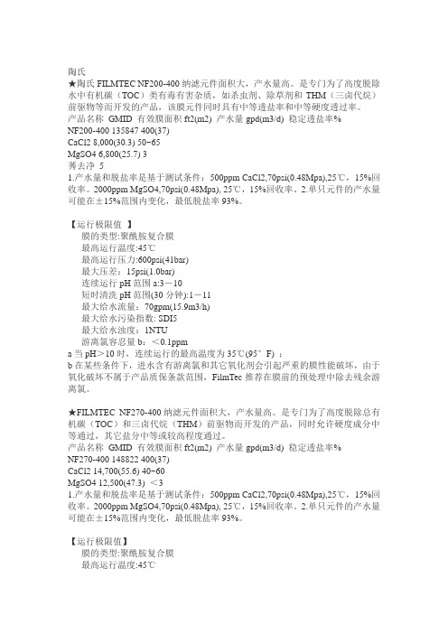
陶氏★陶氏FILMTEC NF200-400纳滤元件面积大,产水量高。
是专门为了高度脱除水中有机碳(TOC)类有毒有害杂质,如杀虫剂、除草剂和THM(三卤代烷)前驱物等而开发的产品,该膜元件同时具有中等透盐率和中等硬度透过率。
产品名称GMID 有效膜面积ft2(m2) 产水量gpd(m3/d) 稳定透盐率%NF200-400 135847 400(37)CaCl2 8,000(30.3) 50~65MgSO4 6,800(25.7) 3莠去净51.产水量和脱盐率是基于测试条件:500ppm CaCl2,70psi(0.48Mpa),25℃,15%回收率。
2000ppm MgSO4,70psi(0.48Mpa), 25℃,15%回收率。
2.单只元件的产水量可能在±15%范围内变化,最低脱盐率93%。
【运行极限值】膜的类型:聚酰胺复合膜最高运行温度:45℃最高运行压力:600psi(41bar)最大压差:15psi(1.0bar)连续运行pH范围a:3-10短时清洗pH范围(30分钟):1-11最大给水流量:70gpm(15.9m3/h)最大给水污染指数: SDI5最大给水浊度:1NTU游离氯容忍量b:<0.1ppma当pH>10时,连续运行的最高温度为35℃(95°F) ;b在某些条件下,进水含有游离氯和其它氧化剂会引起严重的膜性能破坏,由于氧化破坏不属于产品质保条款范围,FilmTec推荐在膜前的预处理中除去残余游离氯。
★FILMTEC NF270-400纳滤元件面积大,产水量高。
是专门为了高度脱除总有机碳(TOC)和三卤代烷(THM)前驱物而开发的产品,同时允许硬度成分中等通过,其它盐分中等或较高程度通过。
产品名称GMID 有效膜面积ft2(m2) 产水量gpd(m3/d) 稳定透盐率%NF270-400 148822 400(37)CaCl2 14,700(55.6) 40~60MgSO4 12,500(47.3) <31.产水量和脱盐率是基于测试条件:500ppm CaCl2,70psi(0.48Mpa),25℃,15%回收率。
陶氏4英寸纳滤膜的更换步骤介绍

陶氏4英寸纳滤膜的更换步骤介绍
2020.02.20
陶氏4英寸纳滤膜的更换步骤介绍
陶氏4英寸纳滤膜属于消耗品,基本上每隔一段时间就需要更换,但是有很多用户不知道该怎么更换杭州陶氏4英寸纳滤膜。
今天给大家介绍下陶氏4英寸纳滤膜的更换步骤介绍。
装卸陶氏4英寸纳滤膜的步骤
1、仔细检查上游进水管路并从中除去所有的灰尘、油脂、金属碎剧等,如有必要,应对进水管路和反渗适压力容器进行化学清洗,以保证所有的异物均被有效除去。
2、仔细检查进水质量。
元件安装前,应该让经预处理系统的合格水流过膜压力容器30分钟,同时检查进入反渗透的水质是否符合膜元件进水规范要求,检查管路是否有泄漏。
3、拆下压力容器的端板和止推环。
不同压力容器制造商的端板结构可能不相同,拆卸时应参考其产品示意图。
4、用干净水冲洗已打开的压力容器,除去灰尘和沉积物。
如果需要进一步清洗的话,可做一个大到能填满压力容器内径的拖把,让拖把吸满50%甘油水溶液,在压力容器内来回拖拉几次,直到压力容器内壁干净和润滑为止。
5、安装元件前,要保证安装和投运系统的所有零部件和化学药剂均齐全,预处理系统运转正常。
6、仅当计划马上投运系统,才可打开包装,安装膜,否则应在原包装内密封存放膜。
以上就是陶氏4英寸纳滤膜的更换步骤,希望对大家有所帮助。
膜元件更换方案
氯碱厂膜元件更换方案2015年4月2日目录目录 0一、膜元件布置方式 (1)二、RO系统化学维护药剂的确认及设备维护、完善 (1)三、膜元件更换准备工作 (1)四、拆、装膜元件 (2)五、系统调试 (2)六、运行方式的要求 (3)七、水样分析报告 (4)膜元件更换方案一、膜元件布置方式根据前期系统运行的情况,为便于更加准确、客观的分析陶氏膜和易膜的运行参数的变化,在本次更换易膜时,把陶氏膜和易膜放置于同一系统,以便在相同运行工况情况下,根据两种RO膜的运行参数的变化,更加客观、准确地分析各膜元件的优缺点。
具体布置如下:两套系统中的一段(3支膜壳)膜元件放置:1支膜壳6支陶氏膜元件1支膜壳6支易膜膜元件1支膜壳3支陶氏膜元件+3支易膜膜元件两套系统中二段(两支膜壳)膜元件放置:1支膜壳6支陶氏膜元件1支膜壳6支易膜膜元件二、RO系统化学维护药剂的确认及设备维护、完善2.1RO系统化学维护药剂的确认:根据需要取样分析的数据来看,硫酸盐、硬度指标相对来说较高。
应要求化学药剂供应商再次对原水水质进行分析,并根据新的原水水质数据调整RO系统的药剂(阻垢剂、还原剂及杀菌剂及PH值)的配方、注入剂量和控制参数。
必要时由膜供应商提供药剂。
2.2设备维护、完善:系统流量计,进、出水电导检测设备,阻垢剂计量泵应加强维护,完善其应有的功能作用。
必要时更换新设备。
三、膜元件更换准备工作为了记录每支压力容器和膜元件所处的相对位置,准备一张用于辩别压力容器和膜元件安装位置的示意图,装卸元件的同时,立即在示意图上填写膜元件的序列号(位于元件标签上)作为元件编号,标明压力容器和膜元件位置的示意图将有助于今后跟踪系统中的每一支膜元件运行情况。
装卸元件准备下列物品:✧拆膜工具一套✧加力杠两更✧榔头一把✧推杆两更(具体长度现场定)✧干净的布✧甘油(无甘油时可用RO产水替代润滑)✧记号笔一支四、拆、装膜元件4.1陶氏膜元件替换移位:把完全使用陶氏膜的系统中拆出15支膜元件,用新的易膜膜元件替换上,所处位置与留下的陶氏膜元件在同一段间。
脱盐中清洗纳滤膜的新方法
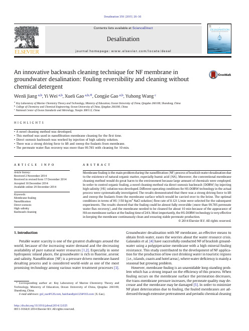
An innovative backwash cleaning technique for NF membrane in groundwater desalination:Fouling reversibility and cleaning without chemical detergentWenli Jiang a ,b ,Yi Wei a ,b ,Xueli Gao a ,b ,⁎,Congjie Gao a ,b ,Yuhong Wang ca Key Laboratory of Marine Chemistry Theory and Technology,Ministry of Education,Ocean University of China,Qingdao 266100,Shandong,Chinab College of Chemistry and Chemical Engineering,Ocean University of China,Qingdao 266100,China cNational Center of Ocean Standards and Metrology,Tianjin 300112,ChinaH I G H L I G H T S •A novel cleaning method was developed.•This method was used in nano filtration membrane cleaning for the first time.•Direct osmosis backwash was worked by injection of high salinity solution.•There was a strong driving force to lift and sweep the foulants from membrane.•The permeate water flux recovery was more than 99.78%with cleaning for 10min.a b s t r a c ta r t i c l e i n f o Article history:Received 2November 2014Received in revised form 17December 2014Accepted 18December 2014Available online 29December 2014Keywords:Membrane fouling Nano filtration Direct osmosis High salinityBackwash cleaningMembrane fouling is the main problem during the nano filtration (NF)process of brackish water desalination due to the existence of natural organic matter,especially humic acid (HA).Moreover,the conventional membrane cleaning method would do great harm to the environment because large amount of chemicals were employed.In order to control organic fouling,a novel cleaning method via direct osmosis backwash (DOBW)by injecting high salinity (HS)solution was developed.Different operating conditions for HS-DOBW technology in the actual process were systematically investigated.The results demonstrated that there was a strong driving force to lift and sweep the foulants from the membrane surface which would be carried over to the brine.The optimal conditions in terms of HS (150kg/m 3NaCl solution)flow rate of 0.121L/min were selected for the subsequent experiments.The results showed that the fouling could be almost fully reversible (more than 99.78%permeate water flux recovery),and the membrane needed to be cleaned for about 10min because of the appearance of HA on membrane surface at the fouling time of 24h.Most importantly,the HS-DOBW technology is very effective in keeping the membrane continuously clean and ensuring stable permeate production.©2014Elsevier B.V.All rights reserved.1.IntroductionPotable water scarcity is one of the greatest challenges around the world,because of the increasing water demand and the decreasing availability of pure natural water resources [1,2].Especially in some hydroponic inland places,the groundwater is rich in fluorine,arsenic and salinity.Nano filtration (NF)is a pressure driven membrane-based desalting process and is considered world-wide as one of the most promising technology among various water treatment processes [3].Groundwater desalination with NF membrane,an effective means to obtain fresh water,eases the worries about the water resource crisis.Galanakis et al.[4]have successfully conducted NF of brackish ground-water using a polypiperazine membrane with a high mineral fouling resistance.This study contributed to the development of NF applica-tion for the production of low cost drinking water in touristic regions (i.e.,islands,coasts and hotel areas),where water de ficiency is mainly a seasonal but growing problem.However,membrane fouling is an unavoidable long-standing prob-lem which has a strong impact on the ef ficiency of this process.When fouling occurs on the membrane surface the permeation decreases,the trans-membrane pressure increases,the permeate quality may de-crease and the membrane may be damaged [5].In order to minimize NF plant deterioration due to fouling,the fouled membranes are ad-dressed through extensive pretreatment and periodic chemical cleaningDesalination 359(2015)26–36⁎Corresponding author at:Key Laboratory of Marine Chemistry Theory and Technology,Ministry of Education,Ocean University of China,Qingdao 266100,Shandong,China.E-mail addresses:gxl_ouc@ ,haichaodiyin123@ (X.Gao)./10.1016/j.desal.2014.12.0250011-9164/©2014Elsevier B.V.All rightsreserved.Contents lists available at ScienceDirectDesalinationj o u r n a l h o m e pa ge :ww w.e l s e v i e r.c o m /l o c a t e /d e s a land disinfection[6–9,27].In any case,due to the downtime resulting from frequent NF operation stoppage,these widely used methods will not only result in low effectiveness of production and high cost of cleaning agents,but also create environmental issues related to the waste chemical disposal.Therefore,it is strongly desired tofind a new method to reduce or even eliminate chemical cleaning.Pressure-driven backwashing,which is a common practice in microfiltration and ultrafiltration processes,is an effective means of fouling control.But it is not applied in NF membranes,as the high back-pressure may rupture the composite membranes[6,10].Spiegler and Macleish[6,11]proposed the means of introducing an osmotic driv-ing force for backwashing.Osmotic backwashing can be induced when the feed-side osmotic pressure exceeds the applied hydraulic pressure across the membrane.Development of direct osmosis(DO)technology has been in-creasingly attractive for backwash cleaning of reverse osmosis(RO) because it is highly efficient and eco-friendly[11].Spiegler,Macleish, Semiat's group,Avraham and Liberman et al.[3–6,12–19]have al-ready studied DO technology.Spiegler and Macleish[4,11]investi-gated DOBW of RO membranes and they found thatflux of the RO membrane fouled with ferric hydroxide could be restored after DOBW.However,it took at least30min for each backwash opera-tion.Ando et al.[20,21]implemented a permeate back pressure in the range of0.05–0.3MPa for backwash of a spiral wound RO mem-brane module.Rychen et al.[22]studied a new DOBW process run-ning with no pressure supplied at the permeate side.And then Semiat's group[5,13,23]conducted fundamental research on this conclusion.They studied the effects of feed concentration,backwash time and feed operating pressure on the DOBWflow rate.Soon after-wards,Avraham et al.[5]reported that there were two distinct stages for the permeate backflow rate vs.time.In Stage I,the back-washflow rate was the highest at the beginning and sharply declined with time.In Stage II,the backwashflow rate then slowed down until leveled off[4,13].They suggested that the DOBW period should be controlled within Stage I,maybe less than20s.And theflux of the RO membrane newly fouled by CaCO3could be resumed to its origi-nal level after the DOBW with0.5%NaCl solution over20s.Liberman[24–27]reported a new DOBW technology for RO mem-brane cleaning,where a high salinity solution(HS)was injected into the feed water over a few seconds.It was reported that in a seawater RO desalination process,a super-saline solution made of17%NaCl could be injected to create a net driving force of55bar for the DOBW process[4,26].And now with the development of this technology,it had been applied in four brackish water RO trains at Dshanim Factory in Israel[28].Hitherto a lot of studies on the DOBW method have been con-ducted and all of the above-mentioned researches are about RO membrane.However,there is no study on the DOBW method used for NF membranes.Both RO and NF are all pressure-driven processes, so the HS-DOBW technology may be applied in the NF membrane cleaning.The study of its application in potable water production from salinity-rich groundwater with NF membrane has not been re-ported.Therefore,previous studies provide a preliminary indication regarding the potential of employing the HS-DOBW technique for NF membrane cleaning.In this paper,the main purpose is to investigate the HS-DOBW mechanism for a singleflat sheet NF membrane and identify its main parameters.A simplified mathematical model was developed to predict the DOBW stage accurately and verified by corresponding experiments which is possible to understand and control the back-wash process of zero-applied pressures.Effects of major parameters and operating conditions were systematically investigated and opti-mized via a laboratory-scale operation for future practical imple-mentation in the case of zero-applied pressure,where osmosis forces alone drive the DOBW process,i.e.,atmospheric pressures al-lows on both sides of the NF membrane.2.Theory2.1.Driving force of the HS-DOBW processFig.1illustrates a comparison of the driving force in NF and HS-DOBW processes.Just like reverse osmosis(RO),NF is also a pressure-driven process.And the pressure is provided by exoteric power energy. Unlike NF,osmosis or FO or DO process is driven by the different osmo-sis pressures between two solutions separated by a semi-permeable membrane[29].The semipermeable membrane allows water to sponta-neously pass through it from higher water chemical potential side to the lower side,i.e.,passage of water is from the lower salt concentration side to the higher one because the lower the salt concentration is,the higher the water chemical potential is,which phenomenon was observed in1748[16].And the theoretical osmosis pressureΠof a salt solution can be calculated using the Van't Hoff Eq.(1).Π¼nc∅RTð1Þwhere n is the number of ions;c is the salt concentration(M),ϕis the osmosis coefficient;R is the universal gas constant (0.082057L·atm·K−1·mol−1),and T is the temperature(K).2.2.Simplest mathematical modelThe present simplest mathematical model together with experi-mental data that were assigned to point at two backwash stages com-prises the backwash mechanism.Measurable variables of the DOBW process were needed to verify the theory[23].One of these variables was the DOBWflux through the membrane,dV/dt′:dV t0ÀÁdt0¼A m DdÂ106∂C0;tðÞ∂yð2Þwhere A m(m2)was the membrane area,D(m2/s),d(m),t'(s)and V(t') (mL).C,t and y were dimensionless.A second measurable variable of the DOBW process was the DOBW accumulated volume,V(t'),entering the feed channel at a dimensional time,t'.V(t'),obtained by integrating Eq.(2)with DOBW time,t':V t0ÀÁ¼A m dÂ106Zt∂C0;tðÞ∂y dt:ð3ÞEq.(3)was the main outcome of the DOBW model.It may be applied to experimental data sets for the model's verification,predictability and further understanding,followed by control of the DOBW process.Eq.(3)parison of the driving force in NF and HS-DOBW processes.27W.Jiang et al./Desalination359(2015)26–36has one adjustable parameter,α,which may be determined by fitting Eq.(3)to a speci fic data set.2.3.Foulant lifting and sweepingFig.2shows a schematic of foulant accumulation in NF process and foulant lifting and sweeping during HS-DOBW cleaning [16,28].The ex-perimental situation that underlined the present model is as follows:the DOBW process starts as soon as the NF stops.Physically,after HS solution is injected into the feed water over a few seconds,the start mo-ment of the backwash process is when the net applied pressure drops below the osmotic pressure,Δπ.The HS solution enters the feed channel like a wave which occupies one or two membrane elements and moves towards the brine outlet.This is the moment at which the permeate water start to diffuse through the NF membrane and through the CP layer into the feed region,and then drain away [13].As a result,the foul-ing and/or scaling components are lift up vertically from the membrane surface.Meanwhile,velocity of the HS solution in the feed channel grows on its way to the brine due to the permeate “up ”suction,which induces an additional horizontal force to flush the feed bi-nation of the lifting up with the increased velocity of HS solution pro-vides both stripping and sweeping effects to effectively clean the membrane surface and remove the foulants from the feed spacer.The water,when transfers through the membrane and CP layer,dilutes the salt concentration subject to diffusion and flow laws while possibly removing the fouled layer.It was reported [1]that there were two distinct stages for the permeate back flow rate vs.time.The first backwash stage,characterized by high backwash flow rate,ends when the salt concentration in the CP layer becomes lower than the salt bulk concentration.In Stage II,the backwash flow rate then slows down until leveled off and water keeps diffusing into the feed space against the salt concentration.When no water feed to the membrane,it is reasonable to assume that time dependent water concentration in the feed side of the membrane is continuously reduced towards asymptot-ically pure water level.At the same time,transient process of salt con-centration dilution continues at the feed side.3.Experiments3.1.Reagents and NF membranesAll of the reagents were analytical grade except NaCl,and deionized water (DIW)was used throughout.HS solutions were prepared with in-dustrial grade NaCl.The NF membranes employed in this study were purchased from Zhejiang Mei Technology Co.,Ltd (China).The membranes employed in this experiment were installed in a laboratory-scale NF stack purchased from Shandong Tianwei Mem-brane Technology Co.,Ltd (Shandong,China).The main characteristics of the membranes are listed in Table 1.boratory-scale experimental set-up and synthetic groundwater qualitySchematic diagram of the fouling and subsequent HS-DOBW cleaning experiments performed with the NF-3A membrane in a laboratory-scale cross-flow test unit was shown in Fig.3.The membrane test unit was equipped with a feed reservoir,a pressure vessel containing the mem-brane module,a circulation and pressurization pump with a security value and two pressure gauges,a thermometer for temperature measure-ment in the circulation reservoir [30]of a membrane cell,an automatic circulating cooling device for temperature control,and a flow meter on the feed water pipe.A HS tank,a DIW tank and two peristaltic pumps were added for the process of HS-DOBW.The membrane cell was a rect-angular plate-and-frame unit,containing a flat membrane sheet placed in a rectangular channel of 12.6cm 2effective membrane area.Both perme-ate and retentate were recirculated.The cross flow velocity and the oper-ating pressure were adjusted by using a bypass valve in conjunction with a back-pressure regulator.In this paper synthetic groundwater was prepared according to the ratio of each ion in groundwater in northwest China,and the main ions in the synthetic solution and their corresponding concentrations are shown in Table 2.3.3.Analytical methodsAll the membrane samples were dried at 303.15K in hood for 24h.Subsequently,many relevant tests were measured.The contamination degree of NF membrane and cleaning ef ficiency of HS-DOBW method were measured with attenuated total re flectance-Fourier transform in-frared spectroscopy (ATR-FTIR),energy dispersive spectrometer (EDS)and atomic force microscope (AFM).Permeate flux recovery was also tested to demonstrate the cleaning ef ficiency of the novel technique.In the whole experiment,all samples were diluted to suitable levels for analysis.The content of arsenic in permeate samples was analyzed by using the AFS-230dual-channel atomic fluorescence spectropho-tometer.Each sample was measured five times,so as to get more accu-rate results.The salinity was analyzed by using a conductivity meter (DDS-307A).Table 1The main characteristics of the NF membranes.ItemNF-3AUnit Type bFlat sheet membrane –Material bPolyamide –Surface charge b Negative –NaCl rejection b 38.0%MgSO 4rejection b 99.5%DIW permeability a 57.84L·m −2·h −1Operation pressure b 15–27kg Operation pH b2.0–10.0–Cleaning temperature b54°CNF test condition:NaCl 2g/L &MgSO 42g/L in water at 1.0MPa.aThe values were measured in the study.bInformation was provided by themanufacturer.Fig.2.Schematic of NF:foulant accumulation and HS-DOBW cleaning:foulant lifting and sweeping.28W.Jiang et al./Desalination 359(2015)26–363.3.1.ATR-FTIR analysisIn order to investigate the changes in chemical bonds in membrane surfaces,ATR-FTIR (Tensor 27,BRUKER OPTIK GmbH)was employed.The spectra were recorded in the range of 600–4000cm −1.3.3.2.SEM –EDS analysisThe membrane samples were cut into 6mm ×6mm size and coated with gold powder in the surfaces by a sputter coating machine before the observation of SEM –EDS (XL 30,Philips).The images of membrane surface were taken by SEM,and the surface element contents were analyzed by EDS.To get the average values,5different sites on each of three membrane samples prepared under the same fouling conditions were tested for the element contents [31].3.3.3.Roughness measurementAFM was used to measure the roughness of the membrane surface and examine the cleaning ef ficiency.The force measurements were carried out with a NanoScope 3D multimode AFM controller (Veeco Metrology Group/Digital Instruments).Measurements were per-formed in tapping mode with etched silicon TESP probes (spring constant 42N/m).Resolution of 512×512data points at 1Hz per image was used to collect the images.Membrane samples were cut into 10mm ×10mm size and then were put onto the substrate to be observed.A high accuracy morphology diagram of the membrane surface could be achieved and it re flected the ion repulsion between the membrane surface and the probe.Then the roughness of the membrane surface and the degree of pollution could be reached.3.3.4.Permeate flux analysisFlux (J )is the volume of permeate (V )collected per unit membrane area (A )per unit time (t ),which is calculated as:J ¼V =At :ð4ÞPermeate samples were collected for arsenic concentration and sa-linity determination and the membrane permeate flux was measured at speci fied time intervals.In order to assess the cleaning ef ficiency of HS-DOBW method,flux recovery ratio (FRR)was calculated based on Eq.(5).FRR %ðÞ¼J w −J f wJ iw −J f wÂ100ð5Þwhere J iw is the pure water flux before fouling;J fw is the pure water flux after fouling;and J w is the pure water flux after cleaning.Pure water flux of membrane before and after fouling was measured.It was measured again after chemical cleaning.And all the pure water fluxes were mea-sured under applied pressure of 1.0MPa,cross-flow velocity of 1L/min,and temperature of 20.0±0.3°C.123450.81.01.2J / (L /m 2/h )Time / (min)Fig.4.Effects of HS and DIW flow rate on cleaning ef ficiency.Table 2The main compositions in the synthetic groundwater.Main parameters Concentration Unit K +7.500ppm Na +882.9ppm Ca 2+58.92ppm Fe 3+0.375ppm Cl −653.2ppm SO 42−1271ppm NO 3−0.605ppm Mg 2+61.00ppm HCO 3−108.8ppm As(V)0.7ppm HA30ppmFig.3.Schematic experimental unit for NF fouling and cleaning.29W.Jiang et al./Desalination 359(2015)26–363.4.Membrane fouling and cleaning protocolsEach backwash experiment was conducted after running the exper-imental system for about 15min to assure steady state NF operation.Backwash time starts at the stop moment of the NF process,by stopping the applied pressure as quickly as possible,to minimize the shift time between NF and backwash processes.Several operation conditions such as HS-DOBW feed-flow rate of both draw solution and feed solu-tion,valence state of ions,concentration of HS,the moment to start cleaning and the duration time.Three simple steps were added for HS-DOBW treatment orderly:(1)close the permeate valve V P ,concen-tration valve V C and feed flow valve V F to pause the NF process (full lines in Fig.3);(2)open valve V H ,V HE and V D ,V DE over the desired time to inject HS and DIW into the NF membrane module by two peri-staltic pumps (BT/101S,Baoding Lead Fluid Technology Co.,Ltd,China)to start the HS-DOBW process (dotted lines in Fig.3);and (3)re-sume the normal NF operation via opening V P ,V C and V F after comple-tion of a HS-DOBW treatment.It should be pointed out that one to four conditions were tested in one day during the HS-DOBW trials for optimization of operating conditions and the ef ficiency of HS-DOBW method on NF fouling control would be validated in a long-term contin-uous plant operation in the next study.4.Results and discussion4.1.Optimization of operating conditions for HS-DOBW treatment 4.1.1.Effect of HS-DOBW feed-flow rate on permeate rateFig.4summarized the results of a set of experiments which tested the in fluence of the HS and DIW flow rate.A HS-DOBW run was operat-ed using a HS solution and DIW at a certain flow rate.After the system reached a steady operation,the backwash process was operated for each flow rate.It could be observed that the permeate flux of DIW through the membrane decreased dramatically with the cleaning timefrom 0to 2min and then decreased gently as the cleaning time increased.The reason for this behavior was related to a concentration polarization (CP)effect on the membrane wall.Then the high salinity solution was diluted by the backwash permeate water with cleaning time and the backwash driving force was reduced subsequently.It made no difference among different flow rates by reason of their ana-logical performances.Taking into consideration economic and other fac-tors comprehensively,the flow rate of 0.121L/min was selected for the subsequent experiments.4.1.2.Selection of HS solutions on permeate rateOsmotic pressure (Π)of salt solution was calculated according to Eq.(1)with known density,so as to investigate the effect of valence state on HS-DOBW cleaning ef ficiency and obtain a feasible HS solution.We could clearly see the results in Table 3that the dose of NaCl was the least under the condition of producing the same osmotic pressure.Apparently,the ion quantity of Na 2SO 4and MgCl 2was 1.5times of NaCl and MgSO 4.So the concentration of NaCl and MgSO 4was 1.5times of Na 2SO 4and MgCl 2with the purpose of gaining the same osmot-ic pressure.Meanwhile,effect of different HS solutions on permeate rate were shown in Fig.5.It demonstrated that the permeate fluxes produced by high salinity solutions did not change very signi fipared with the other solutions,NaCl was the most effective one.On the whole,NaCl was selected as the final HS solution thanks to its utmost ef ficiency and least dose.4.1.3.Effect of HS concentration on permeate rateIt was understood that a higher feed concentration will induce a larger driving force and a bigger backwash flow rate according to Eq.(1).Some studies [3,14,16]have found that a HS with osmotic pressure of 35–100bar was needed and the corresponding NaCl con-centration should be 43–136kg/m 3[3]during backwash in RO.NaCl so-lutions with concentration in the range of 50–200kg/m 3were studied,0123451.32.63.95.2J / (L /m 2/h )Time / (min)Fig.6.Effect of HS concentration on permeate rate in HS-DOBW cleaning.Table 4Calculation of osmotic pressure for different potential HS solutions.NaCl concentration (kg/m 3)Osmotic pressure/Π(bar)5040.9310081.8611493.32125102.33136111.33150122.79200163.72123451.21.62.02.4J / (L /m 2/h )Time / (min)Fig.5.Effects of different HS solutions on permeate rate.Table 3The osmotic pressure and required dose of the representative four salts.Salt type Osmotic pressure (MPa)Concentration (mol/L)Salt dose (g)NaCl 7.183 1.587.75MgSO 47.183 1.5180Na 2SO 47.1831142MgCl 27.18319530W.Jiang et al./Desalination 359(2015)26–36so as to obtain a feasible osmotic pressure for NF membrane backwash.Osmolality of the corresponding NaCl solutions at different concentra-tions was measured and then was converted to osmotic pressure (Π)with the known density.The results were also shown in Table 4.The effect of HS concentration on permeate rate was shown in Fig.6.In the case presented,the permeate flux of the HS-DOBW with different NaCl feed concentrations was calculated based on the backwash flow rate.As shown,the flux increased with driving force (osmotic pressure)in the range of 50to 150kg/m 3NaCl solution.While the permeate flux was almost the same with NaCl concentration increased when it went beyond 150kg/m 3.So in order to economize the consumption of chem-ical salts and make it eco-friendly,the NaCl concentration of 150kg/m 3was engaged in the subsequent HS-DOBW cleaning processes.4.2.Membrane foulant identi ficationIt was found that at the initial stage of NF process,the deposition of sulfate and carbonate of calcium was the main cause of membrane fouling.At the later fouling stage,besides calcium salts,complex organic foulant functional groups also deposited onto membrane surface and gradually formed a densely packed fouling layer [31].By contrast with organic foulant,the inorganic one was much easier to be cleaned.The membrane foulants of different operation time were identi fied in detail by ATR-FTIR and SEM –EDX,for the sake of understanding the mem-brane fouling process during NF of brackish groundwater.4.2.1.Analysis by ATR-FTIRIn order to identify the compositions of organic and inorganic deposits on the membrane surfaces at different fouling stages,the FTIR spectra of membrane samples including virgin membrane andfouled membrane were compared and shown in Fig.7.HA was the only organic matter in the NF feed water,so it was necessary to know its molecular structural formula (Scheme 1).As shown in Scheme 1,HA was a complex organic matter with many functional groups of hydroxide radical (–OH)and carboxyl (–COOH).The FTIR spectrum for the virgin NF membrane showed characteristics of both polyamide barrier layer and polysulfone support layer [32–34].The broad band centered at 3550cm −1was attributed to the overlapping of bands from the stretching vibrations of O –H.The band at the range of 1680–1750cm −1was attributed to C _O stretching and blending vibra-tions.It was obvious that the transmittance was getting stronger and stronger with operating time,especially after 24h fouling with the band at the ranges of 3200–3650cm −1and 1680–1750cm −1.This was just because the existence of hydroxide radical (–OH)and carboxyl (–COOH),which indicated the deposition of HA on the membrane surface after 24h fouling.So in order to clean the mem-brane more easily,the cleaning time should be fixed on the operating time of 24h.4.2.2.Analysis by SEM –EDXIn order to characterize the changes in morphology at different fouling stages,membrane samples including virgin membrane,and membranes of different time fouling were analyzed by SEM.From Fig.8,it was observed that after 5h and 12h operation,a large amount of white crystal substances appear in the fouling layer,which should be sulfate and carbonate of calcium as con firmed by ATR-FTIR analyses.After 24h and 36h operation,a densely packed fouling layer which could consist of both organic matters and inorganic salts was observed on the membrane surface.Combined with SEM,EDX was used to analyze the element contents in fouling layers [31,35].The results were shown in Table 5.It was observed that the content of carbon and oxygen was kept changing with fouling time.But the ratio of carbon/oxygen vs.operation time was almost the same as the virgin membrane when the operation time was in the range of 12h.The ratio began to decrease at the fouling time of 24h,which just meant that the HA appeared on the membrane surface after 24h operation,and its weight percent decreased from 5.533to 5.435,while the change was not very obvious.In order to fur-ther con firm the accurate time of HA appearing on membrane surface,the backwash (with NaCl solution,150kg/m 3)cleaning ef ficiencies for membranes with different filtration time had been studied.As shown in Fig.9,at the cleaning time of about 10min,the FRR of membrane with 24,36and 48h filtration reached 99.78%,92.87%and 86.95%,re-spectively.This should be caused by the deposition of organic foulants during NF of brackish groundwater as discussed above,and the osmotic pressure formed by high salinity solution was not suf ficient to remove them.Many studies [2,14,31,36]have suggested that it was easier for the inorganic matters to be cleared from the membrane surface than the organic pollutants.So the critical point of HS-DOBW cleaning was fixed on the operation time of 24h.Then the membrane was easier to be cleaned and its service life could be extended.T r a n s m i t t a n c eWave numbers / (cm -1)parison of the FTIR spectra of NF membrane samples at different fouling stages:(a)virgin membrane,(b)membrane of 5h fouling,(c)membrane of 12h fouling,(d)membrane of 24h fouling and (e)membrane of 120hfouling.Scheme 1.Chemical formula of humic acid (HA).31W.Jiang et al./Desalination 359(2015)26–36。
RO膜拆卸更换及保养方法
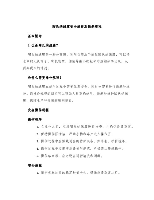
8. 取膜壳微生物样
膜壳完成最终清洗,棉签 擦拭确认清洗效果,并和之 前的分析结果进行对比。
9. RO膜及构件安装
.
按顺序安装RO膜及构件。
10、人工清洗过滤器
11、人工清洗助剂(如阻
检查膜片和垫圈如果发现垫圈损坏或膜片内部有生物膜层需要更取膜壳微生物样膜壳完成最终清洗棉签擦拭确认清洗效果并和之前的分析结果进行对比
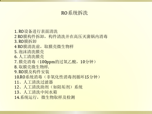
RO系统拆洗
1. RO设备进行表面清洗 2 RO膜构件拆卸,构件清洗并在高压灭菌锅内消毒 3. RO膜拆卸 4 RO膜清洗前,取膜壳微生物样 5. 泡沫清洗膜壳 6. 人工清洗膜壳 7. 膜壳消毒(100ppm的过氧乙酸,10分钟) 8. 取膜壳微生物样. 9. RO膜及构件安装 10.RO系统消毒(非氧化性消毒剂循环15分钟) 11、人工清洗过滤器 12、人工清洗助剂(如阻垢剂)系统 13、人工清洗中间水箱 14.系统运行,微生物取样及检测
将拆卸后的膜置于区域工作台上,膜片的放置都依照拆卸的顺序以免 混乱或不对应的相应外壳。
4 .RO膜清洗前,取膜壳微生物样
在每个膜壳上用棉签进行微生物取 样。
进行
5. 泡沫清洗膜壳
6. 人工清洗膜壳
对膜壳进行人工擦洗以去除附着在上面的薄膜片。含有0.5%的次氯酸 钠泡沫洗涤剂进行擦洗。
7. 膜壳消毒(100ppm的过氧乙酸,10分钟)
1. RO设备进行表面清洗
拆卸RO膜之前,设备区域喷雾消毒。
2. RO膜构件拆卸,构件清洗并在高压灭菌 锅内消毒
取出RO设备构件(密封件、连 接件)并清洗。
在膜壳塞子处能见到一层胶状生物膜异 物。
2. 拆卸RO膜部件,清洗部件并在高压灭菌 器内消毒
更换72支反渗透膜技术要求
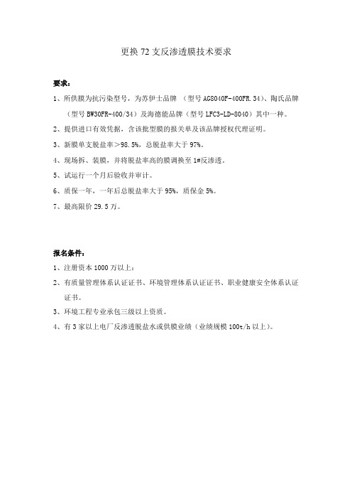
更换72支反渗透膜技术要求
要求:
1、所供膜为抗污染型号,为苏伊士品牌(型号AG8040F-400FR.34)、陶氏品牌
(型号BW30FR-400/34)及海德能品牌(型号LFC3-LD-8040)其中一种。
2、提供进口有效凭据,含该批型膜的报关单及该品牌授权代理证明。
3、新膜单支脱盐率>98.5%,总脱盐率大于97%。
4、现场拆、装膜,并将脱盐率高的膜调换至1#反渗透。
5、试运行一个月后验收并审计。
6、质保一年,一年后总脱盐率大于95%,质保金5%。
7、最高限价29.5万。
报名条件:
1、注册资本1000万以上:
2、有质量管理体系认证证书、环境管理体系认证证书、职业健康安全体系认证
证书。
3、环境工程专业承包三级以上资质。
4、有3家以上电厂反渗透脱盐水或供膜业绩(业绩规模100t/h以上)。
- 1、下载文档前请自行甄别文档内容的完整性,平台不提供额外的编辑、内容补充、找答案等附加服务。
- 2、"仅部分预览"的文档,不可在线预览部分如存在完整性等问题,可反馈申请退款(可完整预览的文档不适用该条件!)。
- 3、如文档侵犯您的权益,请联系客服反馈,我们会尽快为您处理(人工客服工作时间:9:00-18:30)。
专注水处理及流体分离技术
陶氏脱盐型纳滤膜的拆卸更换步骤
即使是再优质的陶氏脱盐型纳滤膜也会有使用周期,当陶氏脱盐型纳滤膜性能饱和时就需要进行拆卸更换,根据陶氏脱盐型纳滤膜的污染程度进行清洗,有的时候甚至需要拆卸进行清洗。
今天,小编就给大家介绍下陶氏脱盐型纳滤膜的拆卸更换步骤吧。
1、先拆卸陶氏脱盐型纳滤膜滤瓶和外壳,注意旋转方向,以免越旋越紧。
2、然后将陶氏脱盐型纳滤膜元件从滤瓶内取出,注意:RO反渗透膜产品推出的时候不要使用坚硬的金属棒,避免损坏膜元件。
3、清洁压力容器:部分设备有这个部件,因此在安装陶氏反渗透膜产品之前清洁压力容器是有必要的,通常建议用海棉球浸入甘油溶液后,在采用专业工具在膜壳内来回擦拭,保障膜壳内部的清洁与卫生。
4、清洁系统水路:假如水路系统是全新的,那么在安装陶氏反渗透膜产品之前就需要对系统水路进行冲洗清洁,以避免碎片、溶剂、余氯等杂质污染膜片。
上述就是陶氏脱盐型纳滤膜的拆卸更换步骤介绍,希望对大家有所帮助。
北京立川环保愿与您携手共同呵护环境。