K文件关键字总结
C语言中32个关键字使用详解
C语言中32个关键字使用详解C语言的关键字共有32个。
根据关键字的作用,可分其为数据类型关键字、控制语句关键字、存储类型关键字和其它关键字四类。
下面是店铺为大家整理的C语言中32个关键字使用详解,欢迎参考~ C语言一共有32个关键字,如下所述:auto :声明自动变量short :声明短整型变量或函数int:声明整型变量或函数long :声明长整型变量或函数float:声明浮点型变量或函数double :声明双精度变量或函数char :声明字符型变量或函数struct:声明结构体变量或函数union:声明共用数据类型enum :声明枚举类型typedef:用以给数据类型取别名const :声明只读变量unsigned:声明无符号类型变量或函数signed:声明有符号类型变量或函数extern:声明变量是在其他文件正声明register:声明寄存器变量static :声明静态变量volatile:说明变量在程序执行中可被隐含地改变void :声明函数无返回值或无参数,声明无类型指针if:条件语句else :条件语句否定分支(与 if 连用)switch :用于开关语句case:开关语句分支for:一种循环语句do :循环语句的.循环体while :循环语句的循环条件goto:无条件跳转语句continue:结束当前循环,开始下一轮循环break:跳出当前循环default:开关语句中的“其他”分支sizeof:计算数据类型长度return :子程序返回语句(可以带参数,也可不带参数)循环条件[C语言中32个关键字详解]。
一、关于起爆点设置的问题:ls-dyna中是通过点来定义起爆的,即关键字

一、关于起爆点设置的问题:LS-DYNA中是通过点来定义起爆的,即关键字*INITIAL_DETONTION,解释一下下面card 的意思,第一个PID,定义炸药的ID,EQ:-1,考虑声学边界,可参考注释中的公式,详细可查看关键字手册;EQ:0,考虑所有炸药。
下面三个数据定义点坐标X,Y,Z的值,LT定义起爆时间。
如果考虑声学边界,则要用到第二个card。
下面纠正一个错误,一直以来很多人都认为设置两个起爆点即为线起爆,这种说法并不准确,k手册中并没有提及到线或面起爆,只是通过点来定义起爆的,因此,定义两个点就叫做线起爆是不对的,从另一个方面分析:线起爆只能通过多个点来近似模拟,并不是真正意义上的线起爆。
关于线起爆的说法,在时老师的书中提到过,在一个例子中,说是采用中心线起爆,设置了两个起爆点。
这个问题我问过时老师,设置两个起爆点就说是线起爆是不准确的,线起爆可以通过多点近似模拟,并不能真正实现线起爆。
所以ls_dyna中只能说是点起爆或者是多点起爆。
补充一下,如果不设置起爆点,则系统会默认为考虑所有炸药同时起爆,下面是一个简单的例子,例子中未设置起爆点,K文件中包含3个part,part1、2为炸药,part3为空气,均采用共节点。
为方便计算,采用“准二维”方式建模,即z轴只有一个单元的厚度。
二、流固耦合流固耦合用以处理流体和结构相互作用的问题,说白了,就是ALE(或者Euler)和lagrange 单元间的耦合。
论坛中有中说法:流固耦合有三种方法,共节点法,接触法,和真正意义上的流固耦合,我觉得这种说法是不准确的,下面解释一下,流固耦合最明显的特征就是在建立模型时,流体和结构(固体)之间必须有重合部分,一般是流体的网格包含结构的网格,举例说明一下,如时党勇一书中,炸药在土壤中的爆炸一例,炸药、土壤、空气、和混凝土板,前三个定义为ALE(流体)单元,混凝土板定义为LAG单元,流体网格包含结构网格,也就是流体和固体之间有重合的网格。
K文件—关键部件的信息情况

关键部件的信息情况1.B柱信息(右B柱的材料、部件、属性编号分别为2000158、2000137、2000186) 材料信息*MAT_PIECEWISE_LINEAR_PLASTICITY$HMNAME MATS 2000185MATL24_200032620001857.8900E-09 210000.0 0.3 400.0 0.0 0.0 0.080.0 4.5 2000006 0 0.0$$ HM Entries in Stress-Strain Curve = 80.0 0.0 0.0 0.0 0.0 0.0 0.0 0.00.0 0.0 0.0 0.0 0.0 0.0 0.0部件信息*part$HMNAME COMPS 2000157CH-B-PILLAR-I-L$HWCOLOR COMPS 2000157 13CH-B-PILLAR-I-L20001572000136 2000185 0 0 0 0 0 属性信息*SECTION_SHELL$HMNAME PROPS 2000136SectShll_20003262000136 2 0.0 3 0.0 0.0 01.328 1.328 1.328 1.328 0.0 0.0 0.0 02.A柱信息(右A柱的材料、部件、属性编号分别为2000150、2000128、2000177) 材料信息*MAT_PIECEWISE_LINEAR_PLASTICITY$HMNAME MATS 2000177MATL24_200031820001777.8900E-09 210000.0 0.3 400.0 0.0 0.0 0.080.0 4.5 2000006 0 0.0$$ HM Entries in Stress-Strain Curve = 80.0 0.0 0.0 0.0 0.0 0.0 0.0 0.00.0 0.0 0.0 0.0 0.0 0.0 0.0 0.0部件信息*part$HMNAME COMPS 2000149CH-A-PILLAR-I-L$HWCOLOR COMPS 2000149 64CH-A-PILLAR-I-L2000149 2000128 2000177 0 0 0 0 0 属性信息*SECTION_SHELL$HMNAME PROPS 2000128SectShll_2000318200012816 0.0 3 0.0 0.0 01.561 1.561 1.561 1.561 0.0 0.0 0.0 0 3.前围板信息材料信息*MAT_PIECEWISE_LINEAR_PLASTICITY$HMNAME MATS 2000211MATL24_200035220002117.8900E-09 210000.0 0.3 250.0 0.0 0.0 0.080.0 4.5 2000003 0 0.0$$ HM Entries in Stress-Strain Curve = 80.0 0.0 0.0 0.0 0.0 0.0 0.0 0.00.0 0.0 0.0 0.0 0.0 0.0 0.0 0.0部件信息*part$HMNAME COMPS 2000183CH-CBN-FIREWALL$HWCOLOR COMPS 2000183 6CH-CBN-FIREWALL20001832000162 2000211 0 0 0 0 0 属性信息*SECTION_SHELL$HMNAME PROPS 2000162SectShll_20003522000162 2 0.0 3 0.0 0.0 00.735 0.735 0.735 0.735 0.0 0.0 0.0 0 4.前纵梁信息(右A柱的材料、部件、属性编号分别为2000218、2000197、2000242) 材料信息*MAT_PIECEWISE_LINEAR_PLASTICITY$HMNAME MATS 2000240MATL24_200038920002407.8900E-09 210000.0 0.3 400.0 0.0 0.0 0.080.0 4.5 2000006 0 0.0$$ HM Entries in Stress-Strain Curve = 80.0 0.0 0.0 0.0 0.0 0.0 0.0 0.00.0 0.0 0.0 0.0 0.0 0.0 0.0 0.0部件信息*part$HMNAME COMPS 2000216CH-RAILS-FT-L-I$HWCOLOR COMPS 2000216 9CH-RAILS-FT-L-I20002162000195 2000240 0 0 0 0 0属性信息*SECTION_SHELL$HMNAME PROPS 2000195SectShll_20003892000195 2 0.0 3 0.0 0.0 01.895 1.895 1.895 1.895 0.0 0.0 0.0 0 5.保险杠信息材料信息*MAT_PIECEWISE_LINEAR_PLASTICITY$HMNAME MATS 2000189MATL24_200033020001897.8900E-09 210000.0 0.3 570.0 0.0 0.0 0.080.0 4.5 2000002 0 0.0$$ HM Entries in Stress-Strain Curve = 80.0 0.0 0.0 0.0 0.0 0.0 0.0 0.00.0 0.0 0.0 0.0 0.0 0.0 0.0 0.0 部件信息*part$HMNAME COMPS 2000161CH-BUMPER-FT-I$HWCOLOR COMPS 2000161 24CH-BUMPER-FT-I2000161 2000140 2000189 0 0 0 0 0 属性信息*SECTION_SHELL$HMNAME PROPS 2000140SectShll_20003302000140 7 0.0 3 0.0 0.0 01.956 1.956 1.956 1.956 0.0 0.0 0.0 0 6.前地板信息材料信息*MAT_PIECEWISE_LINEAR_PLASTICITY$HMNAME MATS 2000212MATL24_200035320002127.8900E-09 210000.0 0.3 330.0 0.0 0.0 0.080.0 4.5 2000005 0 0.0$$ HM Entries in Stress-Strain Curve = 80.0 0.0 0.0 0.0 0.0 0.0 0.0 0.00.0 0.0 0.0 0.0 0.0 0.0 0.0 0.0 部件信息*part$HMNAME COMPS 2000184CH-CBN-FLOORBRD-FT$HWCOLOR COMPS 2000184 7CH-CBN-FLOORBRD-FT20001842000163 2000212 0 0 0 0 0 属性信息*SECTION_SHELL$HMNAME PROPS 2000160SectShll_20003502000160 2 0.0 3 0.0 0.0 00.536 0.536 0.536 0.536 0.0 0.0 0.0 0。
mk文件语法

mk文件语法
“MK文件语法”通常指的是Makefile文件的语法。
Makefile是一种用于自动化构建程序的工具,它描述了如何从源代码生成可执行文件或库文件。
Makefile文件使用特定的语法规则来定义构建规则、依赖关系和编译选项等。
Makefile的语法包括以下部分:
1.变量定义:使用VAR = value的形式定义变量,可以使用${VAR}引用变量
的值。
2.规则定义:使用target: dependencies的形式定义规则,其中target是要
生成的目标文件,dependencies是生成目标文件所需的依赖文件。
例如:hello: main.o utility.ogcc -o hello main.o utility.o
3.命令:定义规则之后可以跟一系列命令,用于生成目标文件。
命令会在执
行Makefile时顺序执行。
例如:%.o: %.cgcc -c $< -o $@
4.条件判断和循环:Makefile支持条件判断和循环结构,可以根据条件执行
不同的命令或重复执行一组命令。
例如:
ifeq ($(CC), gcc)CFLAGS += -O2elseCFLAGS += -O0endif
5.函数:Makefile还提供了一些内置函数,可以在变量、规则和命令中使用。
例如:$(warning "This is a warning message")
以上是Makefile语法的一些基本组成部分。
具体的语法规则和用法可能会根据不同的Makefile版本和工具而有所不同。
C语言的关键字知识要点

C语言的关键字知识要点C语言的关键字知识要点C语言有丰富的数据结构和运算符。
包含了各种数据结构,如整型、数组类型、指针类型和联合类型等,用来实现各种数据结构的运算。
以下是店铺为大家搜索整理的C语言的.关键字知识要点,希望能给大家带来帮助!C语言的关键字共有32个,根据关键字的作用,可分其为数据类型关键字、控制语句关键字、存储类型关键字和其它关键字四类。
1 数据类型关键字(12个):(1) char :声明字符型变量或函数(2) double :声明双精度变量或函数(3) enum :声明枚举类型(4) float:声明浮点型变量或函数(5) int:声明整型变量或函数(6) long :声明长整型变量或函数(7) short :声明短整型变量或函数(8) signed:声明有符号类型变量或函数(9) struct:声明结构体变量或函数(10) union:声明联合数据类型(11) unsigned:声明无符号类型变量或函数(12) void :声明函数无返回值或无参数,声明无类型指针(基本上就这三个作用)(2)控制语句关键字(12个):A循环语句(1) for:一种循环语句(可意会不可言传)(2) do :循环语句的循环体(3) while :循环语句的循环条件(4) break:跳出当前循环(5) continue:结束当前循环,开始下一轮循环B条件语句(1)if: 条件语句(2)else :条件语句否定分支(与 if 连用)(3)goto:无条件跳转语句C开关语句(1)switch :用于开关语句(2)case:开关语句分支(3)default:开关语句中的“其他”分支Dreturn :子程序返回语句(可以带参数,也看不带参数)3 存储类型关键字(4个)(1)auto :声明自动变量一般不使用(2)extern:声明变量是在其他文件正声明(也可以看做是引用变量)(3)register:声明积存器变量(4)static :声明静态变量4 其它关键字(4个):(1)const :声明只读变量(2)sizeof:计算数据类型长度(3)typedef:用以给数据类型取别名(当然还有其他作用(4)volatile:说明变量在程序执行中可被隐含地改变【C语言的关键字知识要点】。
c语言32个关键字详解
c语言32个关键字详解C语言是一种广泛使用的编程语言,它的设计初衷是为了实现操作系统和系统软件。
C语言具有高效、可移植和可扩展性等特点,在计算机领域中拥有广泛的应用。
C语言中有32个关键字,它们是语言中的特定单词,具有特殊含义,可以用于定义变量、控制程序流程、操作内存等。
本文将详细介绍C语言的32个关键字,并讨论它们的用法和作用。
1. autoauto是C语言的一个关键字,用于定义局部变量。
在函数内部定义的变量默认为auto类型,它的生命周期与函数的生命周期相同。
auto关键字可以省略,编译器会自动识别变量类型。
2. breakbreak是C语言中的一个关键字,用于跳出循环语句。
当执行到break语句时,程序会立即跳出当前循环,并执行下一条语句。
3. casecase是C语言中的一个关键字,用于在switch语句中定义分支条件。
case语句后面跟着一个常量表达式,当switch语句的表达式与case语句的常量表达式匹配时,程序会执行该分支语句。
4. charchar是C语言中的一个关键字,用于定义字符类型变量。
char 类型的变量通常用于存储单个字符,它占用一个字节的内存空间。
5. constconst是C语言中的一个关键字,用于定义常量。
const关键字可以用于修饰变量、函数参数和函数返回值,表示它们的值是不可修改的。
6. continuecontinue是C语言中的一个关键字,用于跳过当前循环的剩余语句,执行下一次循环。
当执行到continue语句时,程序会跳过当前循环的剩余语句,并开始下一次循环。
7. defaultdefault是C语言中的一个关键字,用于定义switch语句的默认分支。
当switch语句的表达式与所有case语句的常量表达式都不匹配时,程序会执行default分支语句。
8. dodo是C语言中的一个关键字,用于定义do-while循环语句。
do-while循环语句先执行一次循环体,然后判断循环条件是否成立,如果成立则继续执行循环体,否则退出循环。
C语言32个关键字总结
C语言关键字所谓关键字就是已被C语言编辑工具本身使用, 不能作其它用途使用的字。
C语言的关键字共有32个,根据关键字的作用,可分其为数据类型关键字、控制语句关键字、存储类型关键字和其它关键字四类。
auto double int struct break else long switchcase enum register typedef char extern return unionconst float short unsigned continue for signed voidDefault goto sizeof volatile do while static if1 数据类型关键字(12个):(1)char:声明字符型变量或函数例:char c;用来定义为字符型变量。
它的范围通常为1个字节。
它在内存中是以ASC||玛来表示的。
所以它也可以跟整型来运算。
也可使用无符号或有符号来定义。
(2) double :声明双精度变量或函数例:double name;用来声明为双精度类型。
它的范围为8个字节。
14位为小数位。
也可使用更高精度的long double 它的范围则更大,达到10字节。
(3)enum:声明枚举类型enumday{one,two,three,four,five,six,seven };用来声明枚举变量。
(4) float:声明浮点型变量或函数例:float name;用来声明变量的类型。
float为浮点型,也叫实型。
它的范围固定为4个字节。
其中6位为小数位。
其他为整数位。
(5) int:声明整型变量或函数例:int num;用来声明变量的类型。
int为整型。
注意在16位和32位系统中它的范围是不同的。
16位中占用2个字节。
32位中占用4个字节。
还可以显式的声明为无符号或有符号:unsigned int signed int .有符号和无符号的区别就是把符号位也当作数字位来存储。
c语言32个关键字详解

c语言32个关键字详解C语言是一种广泛应用的编程语言,是许多其他编程语言的基础。
C语言中有32个关键字,这些关键字在编程中具有特殊的含义和功能。
本文将详细介绍这32个关键字,让大家更好地理解和掌握C语言的编程思想和方法。
1. autoauto是C语言中的一个关键字,用于声明自动变量。
自动变量是指在函数内部定义的变量,它们的生命周期与函数的调用和返回有关。
auto关键字可以省略,因为在C语言中默认为auto类型。
2. breakbreak是C语言中的一个关键字,用于跳出循环语句。
当程序执行到break语句时,程序会立即跳出当前循环语句,继续执行后面的语句。
3. casecase是C语言中的一个关键字,用于switch语句中的分支语句。
case后面跟着一个常量表达式,当switch语句中的表达式值与case 后面的常量表达式相等时,程序会执行该分支语句。
4. charchar是C语言中的一个关键字,用于声明字符类型的变量。
char 类型的变量只能存储一个字符,其取值范围是-128到127。
5. constconst是C语言中的一个关键字,用于声明常量。
const关键字可以用于修饰变量或函数的返回值,表示它们是只读的。
一旦被定义为const类型,变量的值就不能被修改。
6. continuecontinue是C语言中的一个关键字,用于跳过当前循环中的某次迭代。
当程序执行到continue语句时,会立即跳过当前循环中的剩余语句,开始下一次迭代。
7. defaultdefault是C语言中的一个关键字,用于switch语句中的默认分支。
当switch语句中的表达式值与所有case后面的常量表达式都不相等时,程序会执行default分支语句。
8. dodo是C语言中的一个关键字,用于do-while循环语句。
do-while 循环语句会先执行一次循环体中的语句,然后再根据循环条件判断是否继续执行循环。
9. doubledouble是C语言中的一个关键字,用于声明双精度浮点数类型的变量。
Java最常用关键字大全(实用版)

Java最常用关键字大全(实用版)本文将介绍 Java 编程语言中最常用的关键字。
关键字是编程语言中具有特殊意义的标识符,它们被用于控制程序的流程、定义变量和类型以及实现不同的功能。
以下是 Java 最常用的关键字:- abstract:用于声明抽象类或抽象方法。
抽象类不能被实例化,只能被继承。
抽象方法只有声明而没有实现。
abstract:用于声明抽象类或抽象方法。
抽象类不能被实例化,只能被继承。
抽象方法只有声明而没有实现。
- assert:用于在代码中进行断言检查,确保程序的正确性。
assert:用于在代码中进行断言检查,确保程序的正确性。
- boolean:表示布尔类型,可以取值为true 或false。
boolean:表示布尔类型,可以取值为 true 或 false。
- break:用于跳出当前循环或开关语句块。
break:用于跳出当前循环或开关语句块。
- byte:表示字节类型,用于存储较小的整数值。
byte:表示字节类型,用于存储较小的整数值。
- case:用于在开关语句中进行匹配选项的比较。
case:用于在开关语句中进行匹配选项的比较。
- catch:用于捕获和处理异常。
catch:用于捕获和处理异常。
- char:表示字符类型,用于存储单个字符。
char:表示字符类型,用于存储单个字符。
- class:用于定义类。
class:用于定义类。
- const:不再使用,替代者为 final。
const:不再使用,替代者为 final。
- continue:用于跳过当前循环的剩余部分,继续下一次循环。
continue:用于跳过当前循环的剩余部分,继续下一次循环。
- default:在开关语句中的默认选项。
default:在开关语句中的默认选项。
- do:用于执行循环体至少一次。
do:用于执行循环体至少一次。
- double:表示双精度浮点数类型。
double:表示双精度浮点数类型。
- else:在 if-else 条件语句中的另一个分支。
dyna中K关键字整理

一,Supported LS-DYNA KeywordsThe following gathers the supported keywords and their syntax for Explicit Dynamics (LS-DYNA Export) systems. The exported keyword file follows the same format as the corresponding Mechanical APDL application. Keywords conform to the “LS_DYNA Keyword User’s Manual” versions 970 and 971 (version 971 has particular features for the handling of beam cross section and integration options).Each keyword consists of one or more cards, each with one of more parameters. If a parameter is not shown, it will be assigned default values by the LS-DYNA solver. In addition some descriptions to Workbench features that do not relate directly to keywords are given at the end of this section, entitled General Descriptions.1,*BOUNDARY_NON_REFLECTINGSpecifies impedance boundaries. Impedance boundaries can only be applied on solid elements in LS-DYNA.Card∙SSID = ID of segment on whose nodes the boundary is applied (see *SET_SEGMENT bellow).∙AD = 0.0 (default) for setting the activation flag for dilatational waves to on.∙AS = 0.0 (default) for setting the activation flag for shear waves to on.2,*BOUNDARY_PRESCRIBED_MOTION_NODE_IDSee *BOUNDARY_PRESCRIBED_MOTION_SET3,*BOUNDARY_PRESCRIBED_MOTION_RIGID_IDSee *BOUNDARY_PRESCRIBED_MOTION_SET4,*BOUNDARY_PRESCRIBED_MOTION_SET_IDSpecifies velocity and displacement boundary conditions.Card required for keyword option ID.∙ID = ID of the prescribed motion keyword. This parameter is optional and does not have to be unique. An index number is added.∙HEADING = Name of the specific boundary condition load. The name is taken from the caption of the applied velocity or displacementin the tree outline of the Mechanical application.Card1∙ID = ID of set of nodes or part (for rigid bodies) to which the boundary condition is applied.∙DOF = 1, 2 or 3 depending whether the boundary condition is in the x, y or z direction respectively. Setting 4 is used if the boundaryis applied according to a local coordinate system.∙VAD = 0 or 2 depending whether the boundary condition is velocity or displacement.∙LCID = ID of the curve prescribing the magnitude of the boundary condition. Constant values of velocity are applied as a stepfunction from time = 0. Constant values of displacement are ramped from zero at time = 0 to the constant value at termination time.This is done to make sure that displacements are applied in atransient fashion.∙SF = 1.0 (default) scale factor for load curve.∙VID = 0 (default). ID of vector that defines the local coordinate system the boundary condition is applied with.∙DEATH = 0.0 (default), sets it to 1E28.∙BIRTH = 0, the motion is applied from the beginning of the solution. Card2: not required.5,*BOUNDARY_SPC_SETSpecifies Fixed Support, Simple Support and Fixed Rotation constraints. Card∙NSID = ID of set of nodes to which the boundary is applied.∙CID = ID of the associated coordinate system. 0 specifies the global coordinate system.∙DOFX = 0 or 1 for free or fixed translation, respectively, along the x direction. It is set to 0 for Fixed Rotation and to 1 otherwise.∙DOFY = 0 or 1 for free or fixed translation, respectively, along the y direction. It is set to 0 for Fixed Rotation and to 1 otherwise.∙DOFZ = 0 or 1 for free or fixed translation, respectively, along the z direction. It is set to 0 for Fixed Rotation and to 1 otherwise.∙DOFRX = 0 or 1 for free or fixed translation, respectively, along the x direction. It is set to 0 for Simple Support and to 1 otherwise.∙DOFRY = 0 or 1 for free or fixed translation, respectively, along the y direction. It is set to 0 for Simple Support and to 1 otherwise.∙DOFRZ = 0 or 1 for free or fixed translation, respectively, along the z direction.. It is set to 0 for Simple Support and to 1otherwise.6,*CONSTRAINED_RIGID_BODIESSpecifies rigid bodies to be merged into one part. The resulting Part ID matches the ID of the rigid body designated as the master.This keyword is created for rigid bodies which belong to the same multibody part. By constraining the rigid bodies together using a single multibody part you avoid specifying conflicting motion on the nodes shared among the rigid bodies. All boundary conditions applied to the master body will also be applied to all the slaves. Any boundary conditions that were applied to the slaves will be ignored.The body that is selected to be master is the first one that appears in the multibody-part list.Card∙PIDM = ID of the master rigid body.∙PIDS = ID of the slave rigid body.7,*CONSTRAINED_SPOTWELDSpecifies spot welds between non-contiguous nodal pairs of shell elements. This keyword is created when a spot weld contact is defined in the Mechanical application.Card∙N1 = ID of the first node used in the weld.∙N2 = ID of the second node present in the weld.∙SN = Normal force at weld failure.∙SS = Shear force at weld failure.∙N = Exponent of normal force.∙M = Exponent of shear force.8,*CONTACT_AUTOMATIC_GENERALSpecifies friction or frictionless contacts between line bodies (beams). This keyword is created if the contact is specified using Body Interactions and the geometry contains line bodies.All the parameter cards are the same as in*CONTACT_AUTOMATIC_SINGLE_SURFACE.9,*CONTACT_AUTOMATIC_NODES_TO_SURFACESpecifies nodes-to-surface friction or frictionless contacts. This keyword is created if the contact is specified using a Contact Region and the Behavior is set to Asymmetric.Card1 - mandatory∙SSID = ID for the set of slave nodes involved in the contact.∙MSID = ID for the set of master segments involved in the contact.∙SSTYP = 4, the slave entities for the contact are nodes.∙MSTYP = 0, the master entities for the contact are segments.∙SBOXID, MBOXID, SPR and MPR are the same as in*CONTACT_AUTOMATIC_SINGLE_SURFACE.Parameter Card2 and Card3 is the same as in*CONTACT_AUTOMATIC_SINGLE_SURFACE.10,*CONTACT_AUTOMATIC_SINGLE_SURFACESpecifies friction or frictionless contacts between parts. This keyword is created if the contact is specified using Body Interactions.Card1 - mandatory∙SSID = ID for the set of parts created for the bodies in the Body Interaction. If the contact is applied to all the bodies in the geometry then this parameter is set to 0.∙MSID = 0.∙SSTYP =2, the slave entities are parts. If the contact is applied to all the bodies in the geometry then this parameter is set to 5.∙MSTYP = 2, the master entities are parts. If the contact is applied to all the bodies in the geometry then this parameter is set to 0.∙SBOXID = It is not used, will be left blank.∙MBOXID = It is not used, will be left blank.∙SPR = 1 (constant) requests that forces on the slave side of the contact be included in the results files NCFORC (ASCII) and INTFOR(binary). These two results files are not currently specified in the exported K file and are not created. The user will need tomanually specify the *DATABASE_NCFORC and *DATABASE_BINARY_INTFORkeywords to obtain them.∙MPR = 1 (constant) requests that forces on the master side of the contact be included in the results files NCFORC (ASCII) and INTFOR(binary). These two results files are not currently specified inthe exported K file and are not created. The user will need tomanually specify the *DATABASE_NCFORC and *DATABASE_BINARY_INTFORkeywords to obtain them.Card2 - mandatory∙FS = Friction Coefficient value from the inputs for frictional contact.∙FD = Dynamic Coefficient value from the inputs for frictional contact.∙DC = Decay Constant value from the inputs for frictional contact.∙VC = 0 (LS-DYNA default).∙VDC = 10 (constant). This parameter specifies the percentage of the critical viscous damping coefficient to be used in order to avoidundesirable oscillation in the contact.Card3 - mandatory, left blank for defaults to be used.Card A is the same as for *CONTACT_AUTOMATIC_SURFACE_TO_SURFACE. 11,*CONTACT_AUTOMATIC_SURFACE_TO_SURFACEDefines specific surface-to-surface friction or frictionless contacts. This keyword is created if the contact is specified using a Contact Region and the Behavior is set to Symmetric.Card1 - mandatory∙SSID = ID for the set of slave segments involved in the contact.∙MSID = ID for the set of master segments involved in the contact.∙SSTYP = 0, the slave entities for the contact are segments.∙MSTYP = 0, the master entities for the contact are segments.∙SBOXID, MBOXID, SPR and MPR are the same as in*CONTACT_AUTOMATIC_SINGLE_SURFACE.Parameter Card2 and Card3 are the same as in*CONTACT_AUTOMATIC_SINGLE_SURFACE.Card A∙SOFT = 2 except for asymmetric contacts like NODES_TO_SURFACE and unbreakable bonded contacts for which it is set to 1.∙• SOFSCL = left blank, the default value of 0.1 will be used. This scale factor is used to determine the stiffness of the interfacewhen SOFT is set to 1. For SOFT = 2 scale factor SLSFAC (see*CONTROL_CONTACT) is used instead.∙LCIDAB = left blank.∙MAXPAR= left blank.∙SBOPT = 3.∙DEPTH = 5.12,*CONTACT_AUTOMATIC_SURFACE_TO_SURFACE_TIEBREAKSpecifies breakable symmetric bonded contacts. This keyword is created for Bonded contact when the Breakable option is set to Stress Criteria and the contact Behavior is set to Symmetric.Card 1 is the same as in *CONTACT_TIED_SURFACE_TO_SURFACE_OFFSET.Card2 - mandatory∙FS = Normal Stress Limit value for the bonded contact.∙FD = Shear Stress Limit value for the bonded contact.∙DC = 0 (LS-DYNA default). This parameter is not required for bonded contacts.∙VC and VDC are the same as in *CONTACT_AUTOMATIC_SINGLE_SURFACE. Card3 - mandatory, is left blank.Card A is the same as for *CONTACT_AUTOMATIC_SURFACE_TO_SURFACE. 13,*CONTACT_ONEWAY_AUTOMATIC_SURFACE_TO_SURFACE_ TIEBREAKSpecifies breakable asymmetric bonded contacts. This keyword is created for Bonded contact when the Breakable option is set to Stress Criteria and the contact Behavior is set to Asymmetric.Parameter cards are the same as in*CONTACT_AUTOMATIC_SURFACE_TO_SURFACE_TIEBREAK.Card A is not used for this keyword.14,*CONTACT_TIED_NODES_TO_SURFACE_OFFSETSpecifies non breakable asymmetric bonded contacts. This keyword is created for Bonded contacts that are not designated as Breakable whose Behavior is set to Asymmetric. This keyword is not used for Body Interactions as these types of contacts are always symmetric.Card1 - mandatory∙SSID = ID for the set of slave nodes involved in the contact.∙MSID = ID for the set of master segment or for the set of parts involved in the contact.∙SSTYP = 4. SSID indicates the ID for a set of nodes.∙MSTYP = 0, MSID indicates the ID for a set of segments.∙SBOXID, MBOXID, SPR and MPR are the same as in*CONTACT_AUTOMATIC_SINGLE_SURFACE.Card 2 left blank.Card 3∙SFS = left blank, the default value of 1.0 will be used. Default slave penalty stiffness scale factor for SLSFAC (see*CONTROL_CONTACT).∙SFM= left blank, the default value of 1.0 will be used. Default master penalty stiffness scale factor for SLSFAC (see*CONTROL_CONTACT).∙SST = the negative value of:"Maximum Offset" is the Definition parameter available for bondedcontacts and body interactions. "Maximum Offset" is obtained fromthe inputs of the Contact Region of Bonded type.∙MST = SST.15,*CONTACT_TIED_SURFACE_TO_SURFACE_OFFSETSpecifies general non-breakable bonded contacts that are symmetric. This keyword is created for Bonded and non-breakable contacts which are defined by Contact Regions that are Bonded, non-breakable and whose Behavior is set to Symmetric.Card1 - mandatory∙SSID = ID for a set of slave segments or a set of parts involved in the contact.∙MSID = ID for the set of master segments or the set of parts involved in the contact..∙SSTYP = specifies whether the ID used in SSID represents parts or segments. It is set to 0 if SSID represents a set of segments and2 if it represents a set of parts.∙MSTYP = SSTYP.∙SBOXID, MBOXID, SPR and MPR are the same as in*CONTACT_AUTOMATIC_SINGLE_SURFACE.Cards 2 and 3 are the same as in *CONTACT_TIED_NODES_TO_SURFACE_OFFSET. Card A is the same as for *CONTACT_AUTOMATIC_SURFACE_TO_SURFACE. 16,*CONTROL_ACCURACYSpecifies control parameters that can improve the accuracy of the calculation.Card∙OSU = 1. Global flag for objective stress updates. Required for parts that undergo large rotations. When set to 1 the flag is on.∙INN = 4. Invariant node numbering for shell and solid elements. When set to 4 the flag is on for both shell and solid elements. 17,*CONTROL_BULK_VISCOSITYSets the bulk viscosity coefficients globally.Card∙Q1 = Quadratic Artificial Viscosity from the "Damping Controls" in the Analysis Settings.∙Q2 = Linear Artificial Viscosity from the "Damping Controls" in the Analysis settings.∙TYPE = -2. Internal energy dissipated by the viscosity in the shell elements is computed and included in the overall energy balance. 18,*CONTROL_CONTACTSpecifies the defaults for computations of contact surfaces.Card 1∙SLSFAC = 0 (default). Scale factor for sliding interface penalties.When set to 0 the value used is 0.1. This scale factor together withthe SFS and SFM parameters of the individual contact keyword (seeCard 3 of *CONTACT_TIED_NODES_TO_SURFACE_OFFSET) is used todetermine the stiffness of the interface when SOFT is set to 2 (seeCard A of *CONTACT_AUTOMATIC_SURFACE_TO_SURFACE).∙RWPNAL = 0 (there is no default value). Scale factor for rigid wall penalties. When equal to 0 the constrain method is used and nodalpoints which belong to rigid bodies are not considered.∙ISLCHK = 1 (default). Initial penetration check in contact surfaces.When set to 1 there is no checking.∙SHLTHK = 1 (default). Shell thickness considered in surface to surface and node to surface contact types. When set to 1, thicknessis considered but rigid bodies are excluded.∙PENOPT = 1 (default). Penalty stiffness value option.∙THKCHG = 0 (default).∙ORIEN = 2. Automatic reorientation for contact segments during initialization. When set to 2 it is active for manual (segment) and automated (part) input.∙ENMASS = 0 if the Retain Inertia Of Eroded Material option of the Erosion Controls in the Details window of the analysis settings is set to No.= 2 (default) if Retain Inertia Of Eroded Material option of the Erosion Controls in the Details view of the analysis settings is set to Yes.This parameter regulates the treatment of the mass for eroded nodes in contact. When set to 0 eroding nodes are removed from thecalculation.Card 2∙USRSTR = 0. Storage per contact interface for user supplied interface control subroutine. When set to 0 no input data is read and no interface storage is permitted in the user subroutine.∙Default values are used for all other parameters.Card3∙SFRIC = 0. Default static coefficient of friction.∙Default values are used for all other parameters.Card4∙IGNORE = 2. Specifies whether to ignore initial penetrations in the *CONTACT_AUTOMATIC options. When set to 2 initial penetrations are allowed to exist by tracking them. Also warning messages are printed with the original and the recommended coordinates of each slave node.∙FRCENG = 0 (default).∙SKIPRWG = 0 (default).∙OUTSEG = 1. Yes, output each beam spot weld slave node and its master segment for *CONTACT_SPOTWELD into D3HSP file.∙SPOTSTP = 0 (default).∙SPOTDEL = 1.Yes, delete the attached spot weld element if the nodes of a spot weld beam or solid element are attached to a shell element that fails and the nodes are deleted.∙SPOTHIN = 0.5. This factor can be used to scale the thickness of parts within the vicinity of the spot weld. This factor helps avertpremature weld failures due to contact of the welded parts with theweld itself. Should be greater than zero and less than one. 19,*CONTROL_ENERGYSpecifies the controls for energy dissipation options.Card∙HGEN = 2. Hourglass energy is computed and included in the energy balance. Results are reported in ASCII files GLSTAT and MATSUM.∙RWEN = 2 (default).∙SLNTEN = 2. Sliding interface energy dissipation is computed and included in the energy balance. Results are reported in ASCII filesGLSTAT and SLEOUT.∙RYLEN = 2. Rayleigh energy dissipation is computed and included in the energy balance. Results are reported in ASCII file GLSTAT. 20,*CONTROL_HOURGLASSSpecifies the global hourglass parameters.Card∙IHQ = 1 if Hourglass Damping of type Standard is selected in the Analysis Settings. Also this parameter is equal to 1 if the Flanagan Belytschko option is selected but both the coefficients are zero.= 5 if the Flanagan Belytschko option is selected and the Stiffness Coefficient is non-zero.= 3 if the Flanagan Belytschko option is selected, the Stiffness Coefficient is zero and the Hex Integration Type of the SolverControls is set to Exact.= 2 if the Flanagan Belytschko option is selected, the Stiffness Coefficient is zero and the Hex Integration Type of the SolverControls is set to 1pt Gauss.∙QH = Viscous Coefficient of the Hourglass Damping section of the Analysis Settings if IHQ is equal to 1, 2, or 3.= Stiffness Coefficient if IHQ is 5.21,*CONTROL_SHELLSpecifies global parameters for shell element types.Card∙WRPANG = 20 (default).∙ESORT = 1, full automatic sorting of triangular shell elements to treat degenerate quadrilateral shell elements as C0 triangularshells.∙IRNXX = -2, shell normal update option. When set to -2 unique nodal fibers are incrementally updated based on the nodal rotation at the location of the fiber.∙ISTUPD = 4, shell thickness update option for deformable shells.Membrane strains cause changes in thickness in 3 and 4 node shell elements, however elastic strains are neglected. This option is very important in sheet metal forming or whenever membranestretching is important. For crash analysis, setting 4 may improve energy conservation and stability.∙THEORY = 2 (default). Belytschko-Tsay formulation.∙BWC = 1 if Shell BWC Warp Correction option is set to Yes in the Solver Controls section of the Analysis Settings. For this setting, Belytschko-Wong-Chiang warping stiffness is added.= 2 if Shell BWC Warp Correction option is set to No.∙MITER = 1 (default). Plane stress plasticity: iterative with 3 secant iterations.∙PROJ = 1, the full projection method is used for the warping stiffness in the Belytschko-Tsay and Belytschko-Wong-Chiang shell elements. This option is required for explicit calculations. 22,*CONTROL_SOLIDSpecifies global parameters for solid element types.Card∙ESORT = 1, full automatic sorting of tetrahedron and pentahedron elements to treat degeneracies. Degenerate tetrahedrons will be treated as ELFORM = 10 and pentahedron as ELFORM = 15 solidsrespectively (see *SECTION_SOLID).23,*CONTROL_TERMINATIONSpecifies the termination criteria for the solver.Card∙ENDTIM = End Time in the Step Controls section of the Analysis Settings.∙ENDCYC = Maximum Time Steps of the Step Controls section of the Analysis Settings.∙DTMIN = 0.01 (constant).∙ENDENG = Maximum Energy Error from the Step Controls section of the Analysis Settings.∙ENDMAS = Maximum Part Scaling from the Step Controls section of the Analysis Settings, if Automatic Mass Scaling is set to Yes.If Automatic Mass Scaling is set to No, the default value of 0.0 is used.24,*CONTROL_TIMESTEPSpecifies conditions for determining the computational time step. Card∙DTINIT = Initial Time Step from the Step Controls section of the Analysis Settings.∙TSSFAC = Time Step Safety Factor from the Step Controls section of the Analysis Settings.∙ISDO = 0 (default). Basis of time size calculation for 4-node shell elements.∙TSLIMT = Minimum Element Timestep from the Erosion Controls section of the Analysis Settings, if On Minimum Element Timestep is set to Yes. If On Minimum Element Timestep is set to No the default value of 0.0 is used.∙DT2MS = the negative value of Minimum CFL Timestep specified in the Step Controls section of the Analysis Settings, if Automatic Mass Scaling is set to Yes. If Automatic Mass Scaling is set to No the default value of 0.0 is used.∙LCTM = ID of the load curve which uses Maximum Time Step from the Step Controls section of the Analysis Settings.∙ERODE = 1 (constant).∙MS1ST = 0 (default).25,*DAMPING_GLOBALSpecifies the mass weighted nodal damping applied globally to the nodes of deformable bodies and the center of mass of rigid bodies.Card∙LCID = 0, a constant damping factor will be used as specified in VALDMP.∙VALDMP = Static Damping from the Damping Controls section of the Analysis Settings.26,*DATABASE_BINARY_D3PLOTSpecifies the sampling parameters for the binary D3PLOT results plotting file.Card∙DT = Time from the Output Controls section of the Analysis Settings if Save Results on is set to Time.= End Time divided by the Number of Points if Save Results On is set to Equally Spaced Time Points.27,*DATABASE_BINARY_RUNRSFSpecifies the sampling parameters for the RUNRSF restart file.Card∙CYCL = Time Steps from the Output Controls section of the Analysis Settings if Save Restart Files on is set to Time Steps.= Maximum Time Steps divided by the Number of Points if Save Results On is set to Equally Spaced Time Points.28,*DATABASE_ELOUTSpecifies the sampling parameters for the ELOUT results file (stores stress and strain results).Card∙DT = (see *DATABASE_BINARY_D3PLOT).29,*DATABASE_FORMATSpecifies the format in which to write binary results files like D3PLOT and D3THDT.Card∙IFORM = 0, binary results will be written only in the LS-DYNA format. 30,*DATABASE_GLSTATSpecifies the sampling parameters for the GLSTAT results file (stores general energy results).Card∙DT = (see *DATABASE_BINARY_D3PLOT).31,*DATABASE_MATSUMSpecifies the sampling parameters for the MATSUM results file (stores general energy and velocity results as the GLSTAT file but it stores them per body. It is necessary for rigid bodies).Card∙DT = (see *DATABASE_BINARY_D3PLOT).32,*DATABASE_NODOUTSpecifies the sampling parameters for the NODOUT results file (stores displacement and velocity results).Card∙DT = (see *DATABASE_BINARY_D3PLOT).33,*DEFINE_COORDINATE_SYSTEMSpecifies a local coordinate system with three points: one at the local origin, one on the local x-axis and one on the local x-y plane.Card1∙CID = ID of the coordinate system, must be unique.∙XO = global X-coordinate of the origin.∙YO = global Y-coordinate of the origin.∙ZO = global Z-coordinate of the origin.∙XL = global X-coordinate of a point on the local x-axis.∙YL = global Y-coordinate of a point on the local x-axis.∙ZL = global Z-coordinate of a point on the local x-axis.Card2∙XP = global X-coordinate of a point on the local x-y plane.∙YP = global Y-coordinate of a point on the local x-y plane.∙ZP = global Z-coordinate of a point on the local x-y plane. 34,*DEFINE_CURVESpecifies magnitudes that are given in tabular format. Some keywords require magnitudes to be specified as a load curve. Should a constant be needed, it may be represented as a curve by repeating its value for time steps 0 and 1.Card1∙LCID = ID for load curve, is incremented every time a new load curve is defined.Card2, 3, 4...∙ A = abscissa value, usually time.∙O = ordinate (function) value.35,*DEFINE_VECTORSpecifies a vector by defining the coordinates of two points. This keyword defines the local coordinate system with respect to which a*BOUNDARY_PRESCRIBED_MOTION is prescribed. The ID of this coordinate system is specified with parameter CID.Card∙VID = ID of the vector.∙XT = 0, the local x-coordinate of the origin of the coordinate system specified with CID below.∙YT = 0, the local y-coordinate of the origin of the coordinate system specified with CID below.∙ZT = 0, the local z-coordinate of the origin of the coordinate system specified with CID below.∙XH = 1 if the vector has a component in the x direction of the coordinate system specified with CID. Otherwise, this is set to 0.∙YH = 1 if the vector has a component in the x direction of the coordinate system specified with CID. Otherwise, this is set to 0.∙ZH = 1 if the vector has a component in the x direction of the coordinate system specified with CID. Otherwise, this is set to 0.∙CID = ID of the coordinate system used to define the vector. If no coordinate system is specified this parameter is set to 0 to specify the global coordinate system.36,*ELEMENT_BEAMSpecifies beam elements.Card∙EID = ID of the element.∙PID = ID of the part it belongs to.∙N1 = ID of nodal point 1.∙N2 = ID of nodal point 2.∙N3 = ID of nodal point 3, used for cross section orientation. 37,*ELEMENT_SHELLSpecifies three, four, six and eight noded shell elements.Card∙EID = ID of the element.∙PID = ID of the part it belongs to.∙N1 = ID of nodal point 1.∙N2 = ID of nodal point 2.∙N3 = ID of nodal point 3.∙N4 = ID of nodal point 4.∙N5-8 = ID of mid side nodes for six and eight noded shells. 38,*ELEMENT_SOLIDSpecifies 3D solid elements including 10-noded tetrahedrons (second order). Apart from the second order case the two cards are combined into one.Card1∙EID = ID of the element.∙PID = ID of the part it belongs to.Card2∙N1 = ID of nodal point 1.∙N2 = ID of nodal point 2.∙N3 = ID of nodal point 3.∙N4 = ID of nodal point 4.∙.∙.∙.∙N10 = ID of nodal point 10.39,*ENDTerminates the keyword file. It has no parameter cards.二,Equation Of State (EOS) keywordsThe following are descriptions for *EOS keywords natively supported by the LS-DYNA export feature. More generally, any *EOS keyword may be introduced into the export file with the help of Commands objects in the Mechanical application (termed Keyword Snippet when referring to the LS-DYNA solver). To use it, insert a Keyword Snippet under a Geometry body in the Tree Outline. The program will automatically substitute the EOSID parameter, in accordance with the *PART keyword (see below) of the associated body. All other parameters in the Keyword Snippet are transcribed literally, overriding any values that would otherwise derive from the Engineering Data workspace.If the *EOS keyword is entered in a Keyword Snippet anywhere else in the Tree Outline, it will be exported literally and the Engineering Data EOS information will also be exported, if present. This practice is not recommended, however, and a warning is provided in the header of Keyword Snippet objects when detected.1,*EOS_GRUNEISENSpecifies a shock equation of state. This keyword is created when a Shock EOS linear equation of state is present in the properties of a material that is used in the simulation and the Johnson Cook plasticity model is also present. The bilinear version of this equation of state is not currently supported.Card1∙EOSID = ID of the keyword, must be unique between the *EOS keywords.∙ C = parameter C1 for a Linear Shock EOS property.∙S1 = parameter S1 for a Linear Shock EOS property.∙S2 = Parameter Quadratic S2 for a Linear Shock EOS property.∙S3 = 0.∙GAMAO = Gruneisen Coefficient for a Linear Shock EOS property.∙ A = 0.Card2 - mandatory, left blank.2,*EOS_LINEAR_POLYNOMIAL。
C语言的关键字共有32个
一、C语言的关键字共有32个,根据关键字的作用,可分其为数据类型关键字、控制语句关键字、存储类型关键字和其它关键字四类。
1 数据类型关键字(12个):(1) char (柴(发4声)尔):声明字符型变量或函数,(2) double (搭泊):声明双精度变量或函数(3) enum (呢末):声明枚举类型(4) float(佛唠特):声明浮点型变量或函数(5) int(硬特):声明整型变量或函数(6) long(浪):声明长整型变量或函数(7) short(邵特):声明短整型变量或函数(8) signed(塞依特):声明有符号类型变量或函数(9) struct(死爪克特):声明结构体变量或函数(10) union(由内呕):声明共用体(联合)数据类型(11) unsigned(安塞依特):声明无符号类型变量或函数(12) void(外偶德):声明函数无返回值或无参数,声明无类型指针(基本上就这三个作用)2控制语句关键字(12个):A循环语句(1) for(否发4声):一种循环语句(可意会不可言传)(2) do (杜):循环语句的循环体(3) while(外偶):循环语句的循环条件(4) break(波瑞克):跳出当前循环(5) continue(肯忒牛):结束当前循环,开始下一轮循环B条件语句(1) if(诶福): 条件语句[/code(扣的)](2) else(艾斯):条件语句否定分支(与if(诶福) 连用)(3) goto(沟吐):无条件跳转语句C开关语句(1) switch(思维吃) :用于开关语句(2) case(诶斯):开关语句分支(3) default (得儿赴澳特):开关语句中的“其他”分支D返回语句Return(瑞腾儿) :子程序返回语句(可以带参数,也看不带参数)3 存储类型关键字(4个)(1)auto (噢吐):声明自动变量一般不使用(2)extern(艾克斯腾儿):声明变量是在其他文件正声明(也可以看做是引用变量)(3)register(瑞盖斯特):声明积存器变量(4)static (斯搭科特):声明静态变量4 其它关键字(4个):(1)const (考斯特):声明只读变量(2)sizeof(塞兹噢夫):计算数据类型长度(3)typedef(汰泼得福):用以给数据类型取别名(当然还有其他作用(4)volatile(喔赖忒偶):说明变量在程序执行中可被隐含地改变二、C语言中的9中控制语句goto(够头)语句:无条件转向; If(诶福)语句:判断语句;While(外偶)循环语句;do-while(杜-外偶)语句:先执行循环体,然后判断循环条件是否成立. 之后继续循环;for(否发4声)语句:循环,可替代while(外偶)语句; 只是用法不同;break(布瑞科)语句跳出本层的循环;(只跳出包含此语句的循环)continue(肯忒牛)语句:继续(一般放到循环语句里,不在执行它下面的语句,直接跳到判断语句例:for(否发4声)语句,就直接跳到第二个分号处,while(外偶)语句,就直接跳到while(外偶)的括号里;switch(思维吃)语句:多相选择;return(瑞腾儿)语句:返回;浅谈小学生如何学英语英语作为国际通用的语言,随着世界经济的发展和中国加入wto,英语所起的作用越来越大,因此,英语亟待于在我国普及。
C++66个关键字的中文含义

C++66个关键字的中文含义1.asm(汇编),用法如下:asm (指令字符串);允许在C++程序中嵌入汇编代码。
2. auto(自动,automatic)是存储类型标识符,表明变量“自动”具有本地范围,块范围的变量声明(如for循环体内的变量声明)默认为auto存储类型。
3. bool(布尔)类型,C++中的基本数据结构,其值可选为true (真)或者false(假)。
C++中的bool类型可以和int混用,具体来说就是0代表false,非0代表true。
bool类型常用于条件判断和函数返回值。
4. break(中断、跳出),用在switch语句或者循环语句中。
程序遇到break后,即跳过该程序段,继续后面的语句执行。
5. case用于switch语句中,用于判断不同的条件类型。
6. catch catch和try语句一起用于异常处理。
7. char char(字符,character)类型,C++中的基本数据结构,其值一般为0~255的int。
这256个字符对应着256个ASCII码。
char类型的数据需要用单引号’’括起来。
8. class class(类)是C++面向对象设计的基础。
使用class关键字声明一个类。
9. const const(常量的,constant)所修饰的对象或变量不能被改变,修饰函数时,该函数不能改变在该函数外面声明的变量也不能调用任何非const函数。
在函数的声明与定义时都要加上const,放在函数参数列表的最后一个括号后。
在C++中,用const声明一个变量,意味着该变量就是一个带类型的常量,可以代替#define,且比#define多一个类型信息,且它执行内链接,可放在头文件中声明;但在C中,其声明则必须放在源文件(即.C文件)中,在C中const 声明一个变量,除了不能改变其值外,它仍是一具变量。
10. const_cast用法:const_cast (expression)该运算符用来修改类型的const或volatile属性。
列举 dockerfile 关键字 及其解释

列举dockerfile 关键字及其解释Dockerfile 是使用Docker 部署容器化应用时的重要文件,其中包含了容器镜像的构建和配置信息。
而Dockerfile 中的关键字则是构建和配置容器镜像的重要元素,下面是一些常用的关键字以及它们的解释。
1. FROMFROM 是Dockerfile 中使用最广泛的关键字之一,它用于指定基础镜像。
也就是说,我们的容器镜像将基于哪个镜像构建。
例如:FROM ubuntu:18.042. RUNRUN 关键字用于在镜像中运行指令,可以用来执行任何Shell 命令或其他可执行文件。
例如,我们可以使用RUN 关键字来安装一些软件:RUN apt-get update && apt-get install -y nginx3. CMDCMD 关键字用于在容器启动时运行指令。
也就是说,在Dockerfile 中只能使用一次CMD 关键字,用于指定容器启动时默认运行的命令。
例如:CMD ["nginx", "-g", "daemon off;"]这条命令将在容器启动时运行Nginx,并将输出写入到标准输出。
4. EXPOSEEXPOSE 关键字用于在容器镜像中声明将要开放的端口,这些端口不是自动映射到主机端口的,而是供其他容器链接使用。
例如:EXPOSE 805. ENVENV 关键字用于设置容器中的环境变量。
Dockerfile 中可以使用多个ENV 关键字来设置多个环境变量。
例如:ENV NAME John6. ADDADD 关键字用于将本地文件或目录复制到容器镜像中。
例如:ADD ./src /usr/src/app7. COPYCOPY 关键字与ADD 关键字类似,用于将本地文件或目录复制到容器镜像中。
但是COPY 关键字更加简单,只能用于复制本地文件或目录到容器内部。
例如:COPY src /usr/src/app8. ARGARG 关键字用于定义变量,这些变量在构建镜像时可以通过指定参数值来修改。
JAVA中的关键字和保留字
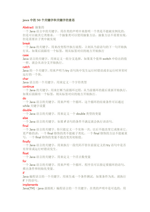
java中的50个关键字和关键字的意思Abstract抽象的一个Java语言中的关键字,用在类的声明中来指明一个类是不能被实例化的,但是可以被其它类继承。
一个抽象类可以使用抽象方法,抽象方法不需要实现,但是需要在子类中被实现break一个Java的关键字,用来改变程序执行流程,立刻从当前语句的下一句开始执行从。
如果后面跟有一个标签,则从标签对应的地方开始执行caseJava语言的关键字,用来定义一组分支选择,如果某个值和switch中给出的值一样,就会从该分支开始执行。
catchJava的一个关键字,用来声明当try语句块中发生运行时错误或非运行时异常时运行的一个块。
charJava语言的一个关键字,用来定义一个字符类型continue一个Java的关键字,用来打断当前循环过程,从当前循环的最后重新开始执行,如果后面跟有一个标签,则从标签对应的地方开始执行。
do一个Java语言的关键字,用来声明一个循环,这个循环的结束条件可以通过while关键字设置double一个Java语言的关键字,用来定义一个double类型的变量else一个Java语言的关键字,如果if语句的条件不满足就会执行该语句。
final一个Java语言的关键字。
你只能定义一个实体一次,以后不能改变它或继承它。
更严格的讲:一个final修饰的类不能被子类化,一个final修饰的方法不能被重写,一个final修饰的变量不能改变其初始值。
finally一个Java语言的关键字,用来执行一段代码不管在前面定义的try语句中是否有异常或运行时错误发生。
float一个Java语言的关键字,用来定义一个浮点数变量for一个Java语言的关键字,用来声明一个循环。
程序员可以指定要循环的语句,推出条件和初始化变量。
ifJava编程语言的一个关键字,用来生成一个条件测试,如果条件为真,就执行if下的语句。
implementsJava(TM)(java虚拟机)编程语言的一个关键字,在类的声明中是可选的,用来指明当前类实现的接口。
