PD204-6C-L3中文资料
士兰微电子LED照明驱动产品及方案-FC

R22 U3 R23
D5
page13
Silan 士兰微电子
AC-DC LED Lighting Solutions AC-DC LED 照明驱动产品及方案
SD7530 功率因数校正控制器
关键参数列表
典型参数 VCC极限电压值 VCC工作电压最大值 VCC开启电压值 VCC关闭电压值 VCC过压保护值 IC启动电流 原边OCP比较点 输入UVLO 输入OVP GATE钳位电压 短路保护
Silan 士兰微电子
DC-DC LED 照明驱动产品及方案
Company Confidential, don’t copy
Silan 士兰微电子
DC-DC LED 照明驱动产品及方案
型号 SD42522 SD42524 SD42525 SD42527 SD42560 SD42565 SD42566 SD42567
SD7530
40V 32V 17V 9V 33.5V 5uA 1.7V 0.95V 4.5V 15V 专利
Company Confidential, don’t copy
page14
Silan 士兰微电子
VCC特性描述
AC-DC LED Lighting Solutions AC-DC LED 照明驱动产品及方案
SILAN LED 照明驱动产品及解决方案
Find what we can do……
Up d 201 ate 2.3
Silan 士兰微电子
LED 照明驱动产品及方案
DC-DC LED 照明驱动产品
◆ SD4252X 系列 -降压型(BUCK) ◆ SD42560 - 升-降压型(BUCK-BOOST) ◆ 80V高压系列(升压SD42566,降压SD42565,升/降压SD42567)
程控直流电源说明书

2
0
安全指导
◇ 可靠性高 具有短路保护、过载保护、过热保护、过压保护、过流保护和独立的温度检测保
护电路。 采用先进的静噪技术,创造安静舒适的工作环境 ◇ 远端测量
远端测量功能可用于补偿输出端子到负载之间的电压降。 ◇ OVP 过电压保护
directcurrentpowersupply直流电源2性能指标型号dlc600020500输入电压范围220v20频率4763hz输出电压020v输出电流0500a负载调整率08满载纹波有效值08高频噪声1负载响应时间1ms数字电压表4位led显示分辨率01v数字电流表4位led显示分辨率01a环境温度550相对湿度9025防护等级ip20大气压力80106kpc海拔2000m以下过电压保护设定输出过压设定值时模块能自动保护并告警
1.2 主要技术特点
◇ 符合中国国家军用标准
GJB572-88《飞机地面电源供电特性及一般要求》的要求 ◇ 符合民用航空行业标准
MH/T 6018-1999《地面静态电源》的要求 ◇ 符合中国国家军用标准
GJB 181A-2003《飞机供电特性》的要求 ◇ 规格多
输出电压0~600V、输出电流0~2000A 、输出功率0-60KW(单机)之内任选。 ◇ 稳压稳流
DLC6000 系列 程控直流稳压稳流电源
用户手册
上海至茂电子科技有限公司
首先,感谢您采用至茂 DLC6000 系列直流电源。
DLC系列大功率稳压稳流直流电源采用国际先进的软开关逆变技术,以德国西 门子IGBT和非晶磁芯为核心器件研制而成,本电源提供了高度稳定的输出电压及电 流,并且提供了极大的便利性,以利于各种的运行模式。本电源提供了可安装于19 寸机柜或桌面机型。本产品配置了10圈精密电位器,用于电压及电流的调整。同时 也提供了数字电压,电流表,使用者可以在设定值,实际值或OVP过电压保护值中 切换。它具有有超高的准确性、高精确度、高稳定性等优良电子特性;所以在研究 单位、在实验室,作为可调电源或是生产线上作为产品寿命测试的固定电源。它确 实是最好的选择。再则它更具有完善的保护线路、与遥控线路;更能满足使用者简 单、方便的使用需求。
Analog Devices EZ-PD CCG3 USB-C电源传输管理器子板演示手册说明书

SYMBOL PARAMETERCONDITIONSMIN TYPMAX UNITSV IN DC2654A Input Voltage Range 520V V OUT DC2654A Output Voltage Range 520V I OUTDC2654A Output Current5A1Rev. 0DESCRIPTIONEZ-PD CCG3USB-C Power Delivery Manager Daughter BoardDemonstration circuit 2654A features the EZ-PD™ CCG3 USB Type-C Port Controller IC designed by Cypress Semiconductor . This product is a daughter board meant to interface with some of Analog Devices’ power product demonstration circuits in order to dem -onstrate their compatibility with the USB Type-C Power Delivery specification.All registered trademarks and trademarks are the property of their respective owners.PERFORMANCE SUMMARYBOARD PHOTOThe default program for this board negotiates a USB Power Delivery profile and chooses the highest voltage advertised by the power adapter plugged into the board, then turns on the power switches to power the main PCB through the banana plugs for a low-impedance connec-tion. Any required digital information is passed between boards through header J3.Design files for this circuit board are available.Specifications are at TA = 25°CRefer to Figure 1, Figure 2 and Figure 3 for the proper equipment setup. Follow the procedure below to familiar-ize yourself with the DC2654A.STANDALONE PROCEDURE1. Connect a voltmeter (VM1) across the V OUT and GND turrets.2. Plug your USB Type-C power adapter into J1 on the DC2654A.3. Observe the voltage on VM1 go to 5V and then to the negotiated voltage (if there is one). The LED on the DC2654A will light as soon as power is delivered to the VM1 node.DEMO BOARD PROCEDURE1. If the demo board is designed to interface with DC2654A, follow any instructions in that board’s demo manual before continuing. If you need to program the DC2654A, refer to the Programming Instructions sec-tion in this manual. If the board is not designed to interface with DC2654A, you can continue, but be sure that the adapter used does not offer a higher profile than the board can withstand.2. Connect a voltmeter (VM1) across the V OUT and GND turrets. Connect DC2654A to the demo board under test.4. Plug your USB Type-C power adapter into J1 on the DC2654A.5. Observe the voltage on VM1 go to 5V and then to the negotiated voltage (if there is one). The LED on the DC2654A will light as soon as power is delivered to the VM1 node.Figure 1. DC2038A is a Battery Charger Demo Board for the LTC4162 Designed to Interface with DC2654A.Figure 2. DC2654A Mounted Onto DC2038AFigure 3. The Banana Plugs and Header on DC2654A Will Fit Snugly Into Compatible Demo Boards.2DEMO MANUAL DC2654A Rev. 0QUICK START PROCEDUREDEFAUL T PROGRAMThe factory-default program on DC2654A is based on the CYPD3125-40LQXI_notebook example project that comes with the EZ-PD CCG3 SDK. The main differences are the addition of variable sink power profile and the operation of the on-board LED. The LED (D1) operates as shown in Table 1.Table 1. LED (D1) OperationLED STATE BOARD STATUSOff Power Switches Off, Load Has No Power On Power Switches On, Load Has at Least 5V BlinkingSMBAlert Is Asserted LowSOURCE MOSFETsComponents M5, M6, R8, and R9 are left unpopulated by default, making DC2654A operate as a sink-only device. In order to operate as a source, these compo-nents can be purchased separately and installed to therelevant footprints. Table 2 shows the part numbers for these components.Table 2. Part Number for Source ComponentsCOMPONENT MANUFACTURER PART NUMBER M5, M6Toshiba SSM6K513NU, LFR8, R9Any 10MΩ 0402Resistor USE WITH CUSTOM DESIGNSWhile in the early design phase, it may be helpful to simply use DC2654A as a simple breakout board for the EZ-PD CCG3. The banana plug outputs have an industry-stan-dard spacing which can serve as an input to many boards with banana jacks. This may serve as a simple way to con-nect any board to a wall outlet using any USB-C adapter . This spacing as well as spacing for the header that mates with J3, can be copied from gerbers for any demo boards compatible with DC2654A (such as DC2038A).Software to interface with specific demo boards can be found on the DC2654A product page. Follow any instruc-tions within those software downloads to program the DC2654A with application-specific firmware examples. The generic software, which just passes a USB-C adapt-er’s highest available voltage to a sink, is also available from the DC2654A product page.MiniProg3 PROGRAMMER/DEBUGGERTo program DC2654A, you will need a MiniProg3 Pro-grammer/Debugger . This can be used for uploading a hex file as well as programming and debugging yourown project. The MiniProg3 can be purchased through Cypress Semiconductor’s website or third-party distribu-tors. The 5-pin header on the MiniProg3 connects to J2 on DC2654A as shown below. The CCG3 can be repro-grammed in-circuit with or without USB power applied.EZ-PD SOFTWARE DEVELOPMENT KITAfter acquiring a MiniProg3 debugger , download the EZ-PD SDK for CCG3. Be sure to consult the instructions in the firmware download for the demo board that you will be interfacing with to determine the version of the SDK that should be used.3DEMO MANUAL DC2654ARev. 0Figure 4. MiniProg3 Connected to DC2654A for Programming and DebuggingBOARD OPERATIONPROGRAMMING INSTRUCTIONSPSoC PROGRAMMERThe quickest way to upload an existing program to the DC2654A is to upload the HEX file using PSoC Program-mer software from Cypress Semiconductor . The HEX file is included in the top-level directory of the DC2654A firm-ware package hosted on the product page of any compat-ible demo board. See Figure 5 for the proper program-ming configuration.PSoC CREATORDC2654A source code can be also programmed and debugged using the PSoC Creator IDE. Firmware down-loads include source code and a PSoC Creator project which can be easily uploaded to the DC2654A. From there,users can modify the code to fit their own requirements and program/debug as necessary.To program DC2654A once a project has been down-loaded, launch PSoC Creator and click the Program button (or Ctrl + F5). This will launch the Select Debug Target dia-log as shown in Figure 6. Click the Port Setting button and verify that the settings match those shown in Figure 7.Ensure that the computer is connected to the MiniProg3 and that the MiniProg3 is connected to the DC2654A. In the Select Debug Target dialog, click the Port Acquire button, and then the Connect button once acquired. Press OK to program the target board.For further instructions, consult PSoC Creator docu-mentation.Figure 5. PSoC Programmer Settings4DEMO MANUAL DC2654A Rev. 0PROGRAMMING INSTRUCTIONSFigure 6. Select Debug Target DialogFigure 7. Port Setting Dialog5DEMO MANUAL DC2654ARev. 0PROGRAMMING INSTRUCTIONSFigure 8. CY4500 EZ-PD Protocol Analyzer Connected Between the DC2654A and a USB PD Wall Adapter6DEMO MANUAL DC2654A Rev. 0PROTOCOL ANALYZERThe CY4500 EZ-PD Protocol Analyzer from Cypress Semiconductor can be used to monitor the USB PD nego-tiation. This is useful for debugging and understanding the data that is being passed between the USB PD adapter and the board under test.The adapter can be connected between the USB PD source providing power and the DC2654A as shown in Figure 8. The micro USB port is then connected to a computerto monitor the data through the supporting GUI from Cypress Semiconductor . Visit the CY4500 product page for more information.Figure 9 shows the negotiation from a power supply offering 3 Power Data Objects (PDOs): 5V/3A, 9V/3A, and 12V/2.25A.Figure 9. Decoded Data from the Protocol Analyzer GUI Showing the Power Data Objects (PDOs) Offered7DEMO MANUAL DC2654ARev. 0PROTOCOL ANALYZER8DEMO MANUAL DC2654A Rev. 0PARTS LISTITEM QTY REFERENCE PART DESCRIPTIONMANUFACTURER/PART NUMBER Required Circuit Components13C1, C2, C9CAP ., 1µF, X5R, 35V, 10%, 0402MURATA, GRM155R6YA105KE11D 22C3, C4CAP ., 390pF, COG, 50V, 5%, 0402AVX, 04025A391JAT2A 31C5CAP ., 0.1µF, X7R, 25V, 10%, 0402AVX, 04023C104KAT2A 43C6-C8CAP ., 2.2µF, X5R, 6.3V, 10%, 0402AVX, 04026D225KAT2A 51D1LED,GREEN, WATER CLEAR, 0603LITE-ON, L TST-C190KGKT 62M1, M2XSTR., MOSFET N-CH, 30V, 15A, UDFN-B EP TOSHIBA, SSM6K513NU,LF 72M3, M4XSTR., MOSFET , DUAL N-CH, 0.28A, SOT-563DIODES INC., 2N7002VAC-782R1, R2RES., 10MΩ, 5%, 1/16W ,0402VISHAY, CRCW040210M0JNED 91R3RES., 1k, 1%, 1/16W, 0402, AEC-Q200VISHAY, CRCW04021K00FKED 102R4, R5RES., 10k, 1%, 1/16W, 0402SAMSUNG, RC1005F103CS 111R6RES., 100k, 1%, 1/10W, 0402, AEC-Q200KOA SPEER, RK73H1ETTP1003F 121R7RES.,200Ω, 5%, 1/2W, 0805, AEC-Q200PANASONIC, ERJP06J201V 131U1IC, USB TYPE-C PORT CONTROLLER, 40-PIN QFNCYPRESS, CYPD3125-40LQXITHardware12E1, E2TEST POINT , TURRET , 0.094" MTG. HOLE, PCB 0.062" THICK MILL-MAX, 2501-2-00-80-00-00-07-022E3, E4CONN., PLUG BANANA, MALE,INTERNAL THREAD KEYSTONE, 607231J1CONN., USB 3.1, RCPT , 24POS, 0.5mm, SMD RA MOLEX, 105450010141J2CONN., HEADER, MALE PIN, 5 POS, 2.54mm, ST THT TE CONNECTIVITY, 640456-551J3CONN., HEADER, MALE, 16 POS, 1.27mm, VERT TALLSAMTEC, FW-08-05-L-D-315-1009DEMO MANUAL DC2654ARev. 0Information furnished by Analog Devices is believed to be accurate and reliable. However , no responsibility is assumed by Analog Devices for its use, nor for any infringements of patents or other rights of third parties that may result from its use. Specifications subject to change without notice. No license is granted by implication or otherwise under any patent or patent rights of Analog Devices.SCHEMATIC DIAGRAMw w w .l i n e a r .c o m10DEMO MANUAL DC2654ARev. 0ANALOG DEVICES, INC. 202012/20ESD CautionESD (electrostatic discharge) sensitive device. Charged devices and circuit boards can discharge without detection. Although this product features patented or proprietary protection circuitry, damage may occur on devices subjected to high energy ESD. Therefore, proper ESD precautions should be taken to avoid performance degradation or loss of functionality.Legal Terms and ConditionsBy using the evaluation board discussed herein (together with any tools, components documentation or support materials, the “Evaluation Board”), you are agreeing to be bound by the terms and conditions set forth below (“Agreement”) unless you have purchased the Evaluation Board, in which case the Analog Devices Standard Terms and Conditions of Sale shall govern. Do not use the Evaluation Board until you have read and agreed to the Agreement. Your use of the Evaluation Board shall signify your acceptance of the Agreement. This Agreement is made by and between you (“Customer”) and Analog Devices, Inc. (“ADI”), with its principal place of business at One Technology Way, Norwood, MA 02062, USA. Subject to the terms and conditions of the Agreement, ADI hereby grants to Customer a free, limited, personal, temporary, non-exclusive, non-sublicensable, non-transferable license to use the Evaluation Board FOR EVALUATION PURPOSES ONL Y. Customer understands and agrees that the Evaluation Board is provided for the sole and exclusive purpose referenced above, and agrees not to use the Evaluation Board for any other purpose. Furthermore, the license granted is expressly made subject to the following additional limitations: Customer shall not (i) rent, lease, display, sell, transfer , assign, sublicense, or distribute the Evaluation Board; and (ii) permit any Third Party to access the Evaluation Board. As used herein, the term “Third Party” includes any entity other than ADI, Customer , their employees, affiliates and in-house consultants. The Evaluation Board is NOT sold to Customer; all rights not expressly granted herein, including ownership of the Evaluation Board, are reserved by ADI. CONFIDENTIALITY. This Agreement and the Evaluation Board shall all be considered the confidential and proprietary information of ADI. Customer may not disclose or transfer any portion of the Evaluation Board to any other party for any reason. Upon discontinuation of use of the Evaluation Board or termination of this Agreement, Customer agrees to promptly return the Evaluation Board to ADI. ADDITIONAL RESTRICTIONS. Customer may not disassemble, decompile or reverse engineer chips on the Evaluation Board. Customer shall inform ADI of any occurred damages or any modifications or alterations it makes to the Evaluation Board, including but not limited to soldering or any other activity that affects the material content of the Evaluation Board. Modifications to the Evaluation Board must comply with applicable law, including but not limited to the RoHS Directive. TERMINATION. ADI may terminate this Agreement at any time upon giving written notice to Customer . Customer agrees to return to ADI the Evaluation Board at that time. LIMITATION OF LIABILITY. THE EVALUATION BOARD PROVIDED HEREUNDER IS PROVIDED “AS IS” AND ADI MAKES NO WARRANTIES OR REPRESENTATIONS OF ANY KIND WITH RESPECT TO IT . ADI SPECIFICALL Y DISCLAIMS ANY REPRESENTATIONS, ENDORSEMENTS, GUARANTEES, OR WARRANTIES, EXPRESS OR IMPLIED, RELATED TO THE EVALUATION BOARD INCLUDING, BUT NOT LIMITED TO, THE IMPLIED WARRANTY OF MERCHANTABILITY, TITLE, FITNESS FOR A PARTICULAR PURPOSE OR NONINFRINGEMENT OF INTELLECTUAL PROPERTY RIGHTS. IN NO EVENT WILL ADI AND ITS LICENSORS BE LIABLE FOR ANY INCIDENTAL, SPECIAL, INDIRECT , OR CONSEQUENTIAL DAMAGES RESUL TING FROM CUSTOMER’S POSSESSION OR USE OF THE EVALUATION BOARD, INCLUDING BUT NOT LIMITED TO LOST PROFITS, DELAY COSTS, LABOR COSTS OR LOSS OF GOODWILL. ADI’S TOTAL LIABILITY FROM ANY AND ALL CAUSES SHALL BE LIMITED TO THE AMOUNT OF ONE HUNDRED US DOLLARS ($100.00). EXPORT . Customer agrees that it will not directly or indirectly export the Evaluation Board to another country, and that it will comply with all applicable United States federal laws and regulations relating to exports. GOVERNING LAW . This Agreement shall be governed by and construed in accordance with the substantive laws of the Commonwealth of Massachusetts (excluding conflict of law rules). Any legal action regarding this Agreement will be heard in the state or federal courts having jurisdiction in Suffolk County, Massachusetts, and Customer hereby submits to the personal jurisdiction and venue of such courts. The United Nations Convention on Contracts for the International Sale of Goods shall not apply to this Agreement and is expressly disclaimed.。
东裕光电科技有限公司产品规格书:红外接收管DY-PT204-6C说明书

广州市东裕光电科技有限公司GUANGZHOU TONYU TECHNOLOGY CO.,LTD产品规格书SPECIFICATION客户名称CUSTOMER 产品名称PRODUCTION红外接收管Photo Transistor产品型号MODEL DY-PT204-6C 版本号VERSION NOA1.0地址(Add):广东省广州市番禺区石基镇海涌路3号10号厂房2楼电话(Tel):************传真(Fax):************邮箱(E-mail):************网址(Net):客户确认CUSTOMER CONFIRMATION 审核CHECKED BY编制PREPARED BY汪建新陈少龙DY-PT204-6C产品描述Descriptions●PT204-6C是一种NPN型高速度和高敏感的光敏三极管.(PT204-6C is an NPN type photosensitive transistor with high speed and high sensitivity.)产品特性Features●响应时间快(Fast response time)●高灵敏度(High photo sensitivity)●引脚间距2.54mm(2.54mm Lead spacing)●无铅(Pb free)●符合RoHS要求(This product itself will remain within RoHS compliant version)产品应用Applications●打印机(Printer)●烟感(Smoke detector)●红外应用系统(Infrared applied system)包装方式Packing Quantity Specification●袋装:1000PCS/袋,4袋/小盒,10小盒/箱(1000PCS/1Bag,4Bags/1Box,10Boxes/1Carton)一、外形图Outline dimensions :Notes:1.All dimensions are in mm,tolerance is ±0.25unless otherwise noted.2.An epoxy meniscus way extend about 1.5mm down the leads.3.Burr around bottom of epoxy may be 0.5mm Max.※备注:承认书之编号和型号可用于查询,客户如有需要,请提供相应的编号和型号。
PD204-6B中文资料

Everlight Electronics Co., Ltd. http:\\ Rev 1.3 Page: 1 of 7Technical Data Sheet3mm Silicon PIN Photodiode T-1PD204-6BFeatures․Fast response time ․High photo sensitivity ․Small junction capacitance ․Pb freeDescriptions․PD204-6B is a high speed and high sensitive PIN photodiode in a standard 3Φplastic package.The device is matched to infrared emitting diode.Applications․Automatic door sensor ․Copier․Game machineDevice Selection Guide ChipLED Part No.MaterialLens ColorPD Silicon Water clearPD204-6BAbsolute Maximum Ratings (Ta=25℃)Parameter Symbol RatingUnits Reverse Voltage V R 32 VOperating Temperature T opr-25 ~ +85 ℃Storage Temperature T stg-40 ~ +85 ℃Soldering Temperature T sol 260 ℃P c 150 mWPower Dissipation at(or below)25℃Free Air TemperatureNotes: *1:Soldering time≦5 seconds.Everlight Electronics Co., Ltd. http:\\ Rev 1.3 Page: 2 of 7Everlight Electronics Co., Ltd. http:\\ Rev 1.3 Page: 3 of 7PD204-6BElectro-Optical Characteristics (Ta=25℃)Parameter Symbol Condition Min Typ Max UnitRang Of Spectral Bandwidth λ0.5 --- 840 --- 1100nm Wavelength Of Peak Sensitivity λP --- --- 940 --- nm Open-Circuit Voltage V OC Ee=5mW/cm 2λp=940nm --- 0.42 --- V Short- Circuit Current I SC Ee=1mW/cm 2 λp=940nm --- 3.0 --- μA Reverse Light Current I L Ee=1mW/cm 2 λp=940nm V R =5V 1.0 3.0 --- μA Reverse Dark CurrentI DEe=0mW/cm 2V R =10V --- --- 10 nAReverse Breakdown Voltage B VR Ee=0mW/cm 2 I R =100μA 32 170 --- VTotal Capacitance C t Ee=0mW/cm 2V R =5V f=1MHz--- 5 --- pFRise Time t r --- 6 ---Fall Timet fV R =10VR L =1000Ω--- 6 --- nSPD204-6BEverlight Electronics Co., Ltd. http:\\ Rev 1.3 Page: 4 of 7Everlight Electronics Co., Ltd. http:\\ Rev 1.3 Page: 5 of 7PD204-6BReliability Test Item And ConditionThe reliability of products shall be satisfied with items listed below.Confidence level:90%Everlight Electronics Co., Ltd. http:\\ Rev 1.3 Page: 6 of 7PD204-6B Packing Quantity Specification2. When using this product, please observe the absolute maximum ratings and the instructionsfor using outlined in these specification sheets. EVERLIGHT assumes no responsibility for any damage resulting from use of the product which does not comply with the absolutemaximum ratings and the instructions included in these specification sheets.3. These specification sheets include materials protected under copyright of EVERLIGHTcorporation. Please don’t reproduce or cause anyone to reproduce them without EVERLIGHT’s consent.Everlight Electronics Co., Ltd. http:\\ Rev 1.3 Page: 7 of 7。
ir2101中文资料

数据表PD60043典型连接具有浮动通道设计的引导操作完全可操作+600V耐受性负转换电压dV/dt免疫网关驱动电源范围从10个欠压锁定3.3V,5V,15V逻辑输入兼容匹配传播延迟两个通道输入(IR2101)输入(IR2102)描述高压,高速功率MOSFET-igbt 驱动器独立的高低压侧参考输出通道。
专有的HVIC latchimmune CMOS技术支持加固单片结构。
逻辑输入标准CMOS LSTLOUTPUT,下降3.3Vlogic。
输出驱动器具有高脉冲电流缓冲高低压侧驱动程序包产品概要偏置600V最大130mA 270mA输出10开/关(典型)160 150ns延迟匹配50 ns IR2101 IR2102 IR2101 LeadSOIC LeadPDIP阶段设计的最小驱动器交叉传导。
浮动沟道can N沟道功率MOSFET高侧配置,工作电压高达600伏。
网站HOLO-COM-HIN-LIN-HIN-up-HOLO-COM-HIN-LIN-HIN-up-CC(参考引线分配修正引脚配置)。
图表仅显示电气连接。
请参阅我们的应用注意事项电路板布局。
第二章:IR2101/符号定义最小最大单元高压侧浮动电源电压-0.3 625高压侧浮动电源偏移电压HO高压侧浮动输出电压CC低压侧逻辑固定电源电压-0.3 25 L低压侧输出电压-0.3逻辑输入电压(HIN LIN)-0.3 0.3dV/dt允许的偏移电源电压瞬变50V/ns包装功耗导线pdip)导线soic)0.625Rth JA热电阻,连接导线pdip)导线soic)接头温度存储温度-55 150导线温度(焊接,10秒)300绝对最大额定值绝对最大额定值指示持续极限,超过该极限值可能会发生损坏设备。
所有电压参数均为绝对电压参考的热电阻功率耗散额定值,在安装在板上的静止空气条件下测量。
SymbolDefinition 最小最大单位高压侧浮动电源绝对电压高压侧浮动电源偏移电压注HO高压侧浮动输出电压CCLow side logicfixed supply voltage 10 20 Low side output voltage Logicinput voltage (HIN LIN)(IR2101)LIN)(IR2102)环境温度-40 125注释逻辑操作+600V。
PD204_6B光敏二极管产品说明书
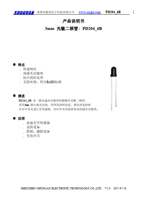
产品说明书3mm光敏二极管:PD204_6B ⏹特点․快速响应․高感光灵敏度․较小的结电容․无铅环保,符合RoHS标准⏹描述PD204_6B是一款高速高灵敏度的插脚式光敏二极管,采用3mm圆头感光结构,用环氧材料封装,黑色封装材料可对可见光进行有效滤除,对红外光均保持很高的感光灵敏度。
⏹应用․高速光学传感器․安防设备․照相、摄影设备․光电开关⏹封装尺寸1.正极2.负极注: 1. 所有尺寸单位为毫米(英寸)2. 未说明误差的尺寸为±0.25mm(0.01英寸)⏹极限参数(Ta=25℃)参数符号参数值单位反向电压VR30V耗散功率Pd150mW焊接温度Tsol260℃工作温度Topr-25~+85℃存储温度Tstg-40~+85℃Ambient Temperature Ta(°C)P o w e r D i s s i p a t i o n (m W )5020020406080100-20-401001501008060200600Wavelength(nm)R e l a t i v e S p e c t r a l S e n s i t i v i t y (%)Ta=25°40700800900100011001200⏹光电参数(Ta=25℃)参数符号条件最小典型最大单位光谱带宽λ0.5---840---1100nm 感光峰值波长λp ------940---nm 开路电压V OC Ee=5m W/cm 2λp=940nm ---0.32---V短路电流I SC Ee=5m W/cm 2λp=940nm ---60---μA反向亮电流I LEe=5m W/cm 2λp=940nm V R =5V5560---μA暗电流Id Ee=0m W/cm 2V R =10V------10nA反向击穿电压BV R Ee=0m W/cm 2I R =100μA 30------V 总计电容CtEe=0m W/cm 2V R =3V f=1MHZ ---12---pF 上升/下降时间t r /t fV R =10V R L =1K Ω25/25nS⏹光电特性曲线图.1耗散功率与环境温度图.2相对频谱灵敏度400Ambient Temperature Ta(°C)R e v e r s e D a r k C u r r e n t (n A )608010020101001000V =10V R1Reverse Voltage (V)T e r m i n a l C a p a c i t a n c e C t (p F )101000.1204060f=1MHzV =3V Ee=0mW cmR2/10Load Resistance R L ( )R e s p o n s e T i m e t r ,t f (u s )10310101010101010101-316012080402.55.07.5Ee(mW/cm )10.02V =5V Rλ=940nm图.3暗电流与环境温度图.4反向感光电流与辐射强度图.5结电容与反向电压图.6响应时间与负载电阻注意事项:1.我公司保留更改产品材料和以上说明书的权利,更改以上产品说明书恕不另行通知。
DC24V输入 输出6串3并 18-21V 0.9A 18W 恒流dcdc洗墙灯电池电瓶灯汽车LED专用电源
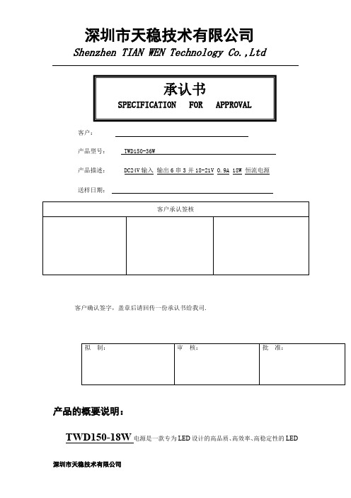
承认书SPECIFICATION FOR APPROVAL客户:产品型号: TWD150-36W产品描述: DC24V输入输出6串3并18-21V 0.9A 18W 恒流电源送样日期:客户承认签核客户确认签字,盖章后请回传一份承认书给我司.拟制:审核:批准:产品的概要说明:TWD150-18W电源是一款专为LED设计的高品质、高效率、高稳定性的LED防水恒流驱动电源。
具有启动快速,兼容负载范围宽,保护功能齐全,采用美国原装进口成熟方案,输入电压DC24V,输出6串3并,电压18-21V,电流0.9A±3%A,高精确的恒流控制,极高的效率和可靠的性能,以及全铝的外观结构会使你的灯具更加趋于安全、稳定。
LED负载概要说明:LED总灯珠规格为VF=DC18-21V,I=0.9A;最大输出18W。
产品电性参数电源型号TWD150-18W电源规格DC24V输入,输出6串3并、18-21V、0.9A、18W防水等级IP67应用太阳能、洗墙灯、工矿灯、矿井、隧道、地铁、码头、工地等产品外壳材料防水电源金色半铝外壳:L54*W25*H21mm 加孔位70*W25*H21mm,两头塑胶,底部没盖产品实测试数据尺寸铝体表面L108×W42×H30 加两端螺丝孔位耳朵L125×W42×H30 标贴1),亚银纸亮光,厚度≤0.1mm。
2),颜色:白底黑字。
产品反面图产品正侧面图产品反侧面图输入特性输入范围DC23-30V 输入频率NA输入电流(Irms)0.5-0.8A 功率因素(PF)NA整机效率94.5% -96%输出特性输出类型恒流(CC) 输出电压18V-21V 输出电流0.9A±3% 输出纹波( <250mV 输出噪音(Vp-p) <500mV 开机时间<1s保护过压保护(OVP) Y 过流保护(OCP) Y 短路保护(OSP) Y 输入低压保护Y 输入高压保护NA环境产品常温最高温度+45℃工作环境温度范围-20℃ - +85℃存储温度-20℃ - +80℃相对湿度10%-90%散热方式自冷接线说明输入400mm黑色橡胶线(2*0.75m㎡)输出300mm黑色橡胶线(2*0.75m㎡)安全标准IEC61347-1:2000 ,IEC61347-2-13, IEC62384 电磁兼容EN55022、EN61000-3-2输入保护功能:1.有防接反电路设计输入,接反会不亮,按正负极接对后就可正常工作,接反不会对电源有任何的损坏。
SPD3000C可编程线性直流电源使用指南说明书

2
SPD3000C 可编程线性直流电源数据手册
技术规格
型号 通道输出 显示 分辨率 设定精度 回读精度
ห้องสมุดไป่ตู้恒压模式
恒流模式 并联模式 串联模式[1]
特性与优点
三路高精度电源独立可控输出: 32V / 3.2A × 2,可切换 2.5V / 3.3V / 5V / 3.2A × 1,总功率 220W 最高 4 位电压和 3 位电流显示,最小分辨率 为 10mV、10mA 三种输出模式:独立,串联和并联连接; 100V / 120V / 220V / 230V 兼容的设计,以 满足不同电网的需求 智能温控风扇,有效降低噪音 内部 5 组系统参数保存/调取,支持数据存 储空间扩展 提供 EasyPower 上位机软件,提供 SCPI 程 控命令集和 LabView 驱动包,满足远程控制 和通信需求
技术许可
对于本文档中描述的硬件和软件,仅在得到许可 的情况下才会提供,并且只能根据许可进行使用 或复制。
SPD3000C 可编程线性直流电源数据手册
5
SPD3000C 可编程线性直流电源数据手册
1
设计特色
高分辨率输出 SPD3000C 可编程线性直流电源最高分辨率为 10mV,10mA,优良的设定和回读精度,确保精确纯净 的输出,即使非常小的电压或电流变化,也能够准确模拟,完全满足负载的供电要求,这是普通的低精 度电源所不能做到的。
串联 / 并联 / 独立模式功能 串并联功能能够将两路电源合并成一路电源使用,扩充了单路电源的输出功率范围,这在一些应用场所 带来了方便。三路独立电源均可单独控制输出开关,也可同时打开或关断,使用起来非常方便。
PanelView 5310 终端 用户手册说明书

目录
概述 安装 PanelView 5310 终端
配置终端设置
前言
变更摘要. . . . . . . . . . . . . . . . . . . . . . . . . . . . . . . . . . . . . . . . . . . . . . . . . 7 包装清单. . . . . . . . . . . . . . . . . . . . . . . . . . . . . . . . . . . . . . . . . . . . . . . . . 7 索取开源软件包的对应源代码 . . . . . . . . . . . . . . . . . . . . . . . . . . . . . . 8 产品固件和发行说明 . . . . . . . . . . . . . . . . . . . . . . . . . . . . . . . . . . . . . . 8 其他资源. . . . . . . . . . . . . . . . . . . . . . . . . . . . . . . . . . . . . . . . . . . . . . . . . 9
第1章
关于 PanelView 5310 终端 . . . . . . . . . . . . . . . . . . . . . . . . . . . . . . . . 11 硬件特性. . . . . . . . . . . . . . . . . . . . . . . . . . . . . . . . . . . . . . . . . . . . . . . . 12 操作员控制. . . . . . . . . . . . . . . . . . . . . . . . . . . . . . . . . . . . . . . . . . . . . . 13 触摸手势. . . . . . . . . . . . . . . . . . . . . . . . . . . . . . . . . . . . . . . . . . . . . . . . 13 Studio 5000 环境 . . . . . . . . . . . . . . . . . . . . . . . . . . . . . . . . . . . . . . . . 14 EtherNet/IP 通信 . . . . . . . . . . . . . . . . . . . . . . . . . . . . . . . . . . . . . . . . 15 典型配置. . . . . . . . . . . . . . . . . . . . . . . . . . . . . . . . . . . . . . . . . . . . . . . . 15 产品目录号说明 . . . . . . . . . . . . . . . . . . . . . . . . . . . . . . . . . . . . . . . . . 15 产品选择. . . . . . . . . . . . . . . . . . . . . . . . . . . . . . . . . . . . . . . . . . . . . . . . 16 附件. . . . . . . . . . . . . . . . . . . . . . . . . . . . . . . . . . . . . . . . . . . . . . . . . . . . 16 以太网电缆. . . . . . . . . . . . . . . . . . . . . . . . . . . . . . . . . . . . . . . . . . . . . . 17
精确保护揽胜未来

目前我国的城市轨道交通(如地铁、轻轨和运行于其上的电力机车、动车 组等)体系均采用直流系统供电。而其直流电源大多由大功率硅整流装置 提供,硅整流装置元器件因过载能力低,对直流电网保护元器件的要求更 高。快速分断的直流专用断路器是轨道交通中的重要元器件。
舰船
在舰船电力系统和电力推进系统中,直流断路器是非常重要的元器件之 一。它对变配电系统和用电设备的故障实施保护,采取多种防护,确保舰 船供电系统和用电设备的安全。
NSX-DC
C65LS-DC C65H-DC NSX-DC LSI
ዷజ၍1 220V(110V)
ዷజ၍2 220V(110V)
NSX-DC
C65LS-DC C65H-DC NSX-DC LSI
ቤተ መጻሕፍቲ ባይዱ
INS
INS
ۉݴೡజ၍
INS
INS
ۉݴೡజ၍
MT-DC LSI
NW-DC HA
NSX-DC LSI
-~
直流电源
信息产业的蓬勃发展迎来了通讯电源、EPS、UPS等直流电源行业的大发 展,基站、数据中心象雨后春笋般地出现在神州大地上。为了保证直流电 源的高精密度要求,作为直流电源中各级馈电回路中最重要的操作和保护 元器件的直流断路器,以其可靠的选择性分级配合对保护设备、限制事故 范围起着非常重要的作用。
客户关爱中心热线:400 810 1315
施耐德电气中国 Schneider Electric China
北京市朝阳区望京东路6号 施耐德电气大厦 邮编: 100102 电话: (010) 8434 6699 传真: (010) 8450 1130
NSX-DC NSX-DC
-~
NW-DC HA
珠海市海威尔电器有限公司 DC DC 电源模块说明书

选型表产品特性封装形式:SIP 7工作温度范围:-40℃-105℃ 隔离电压:3000VDC 效率:最高效率可达89% 符合标准:国际标准引脚方式应用领域:电力、工控、通信、物联网、汽车等#每路输出输入特性输出特性纹波噪声20MHz带宽--45100mVp-p 温度漂移系数满载--±0.03--%/℃短路保护可持续,自恢复通用特性物理特性外壳材料黑色阻燃耐热塑料(UL94V-0)封装尺寸19.65*6.00*10.16mm重量 2.4g冷却方式自然空冷EMC特性EMI 传导骚扰CISPR32/EN55032CLASS B(推荐电路见图5)辐射骚扰CISPR32/EN55032CLASS B(推荐电路见图5)EMS静电放电IEC/EN61000-4-2Contact±8KV perf.Criteria B产品特性曲线图+2.0%-5.0%-12%10%20%40%60%80%100%0%-5%-10%+5%+12%输出电压精度输出电流百分比(标称输入电压).误差包络曲线图(3.3VDC输出)图1Max.Typ.Min.误差包络曲线图(其他输出)+2.5%-2.5%-7.5%10%20%40%60%80%100%+5%0%-5%-10%+10%+15%输出电压精度输出电流百分比(标称输入电压)M a x .T y p .M in .图2外观尺寸/建议印刷版图注:尺寸单位:mm[inch]端子直径公差:±0.10[±0.004]未标注之公差:±0.50[±0.020]引脚功能(单路)功能(双路)1Vin Vin 2GND GND 5-Vo -Vo 6NO PIN COM 7+Vo+VoNC :不能与任何外部电路链接2]0.1.典型应用若要求进一步减小输入输出纹波,可在输入输出端连接一个电容滤波网络,应用电路如图4所示。
但应注意选用合适的滤波电容。
金升阳 LHE20-20Bxx 电源模块产品说明书

20W ,AC-DC 模块电源产品特点●全球通用电压:85-264VAC/100-370VDC ●工作温度范围:-40℃to +85℃●4000VAC 高隔离电压●稳压输出、低纹波噪声●输出短路、过流、过压保护●高效率、高可靠性●全塑料外壳,符合UL94V-0●EMI性能满足CISPR32/EN55032CLASS B●通过IEC62368、UL62368、EN62368认证CB RoHSLHE20-20Bxx 系列-----是金升阳为客户提供的小体积模块式开关电源。
该系列电源具有全球输入电压范围、交直流两用、低功耗、高效率、高可靠性、安全隔离等优点。
产品安全可靠,EMC 性能好,EMC 及安全规格满足IEC62368、CISPR32/EN55032、UL62368和EN62368标准。
该系列产品广泛应用于工业、办公及民用等行业中,当应用于电磁兼容比较恶劣的环境时必须参考应用电路。
选型表认证产品型号输出功率标称输出电压及电流效率(230V AC,%/Typ.)最大容性负载(µF)UL/CE/CBLHE20-20B0311.55W 3.3V/3500mA 7336000LHE20-20B0515.5W5V/3100mA 7712240LHE20-20B0920W9V/2100mA 795600LHE20-20B1212V/1600mA 815000LHE20-20B1515V/1300mA 823000LHE20-20B2424V/850mA84900注:*产品型号后缀加“A2”为接线式封装拓展,后缀加“A4”为导轨式封装拓展,如:LHE20-20B03A2表示接线式封装,LHE20-20B03A4表示导轨式封装。
输入特性项目工作条件Min.Typ.Max.单位输入电压范围交流输入85--264VAC 直流输入100--370VDC 输入频率47--63Hz输入电流115V AC ----0.60A230V AC ----0.34冲击电流115V AC --20--230V AC--30--外接保险管推荐值2A/250V ,慢断,必接热插拔不支持输出特性项目工作条件Min.Typ.Max.单位输出电压精度 3.3V 输出--±3--%其他输出--±2--线性调节率满载--±0.5--负载调节率0%-100%负载--±1--纹波噪声*20MHz 带宽(峰-峰值)--50100mV 温度漂移系数--±0.02--%/℃短路保护打嗝式,可长期短路,自恢复过流保护≥110%Io自恢复过压保护3.3/5VDC输出≤7.5VDC(输出电压钳位或打嗝) 9VDC输出≤15VDC(输出电压钳位或打嗝) 12/15VDC输出≤20VDC(输出电压钳位或打嗝) 24VDC输出≤30VDC(输出电压钳位或打嗝)最小负载0----%掉电保持时间115V AC输入--15--ms 230V AC输入--80--注:*纹波和噪声的测试方法采用平行线测试法,具体操作方法参见《AC-DC模块电源应用指南》。
模拟直流信号光电隔离放大器
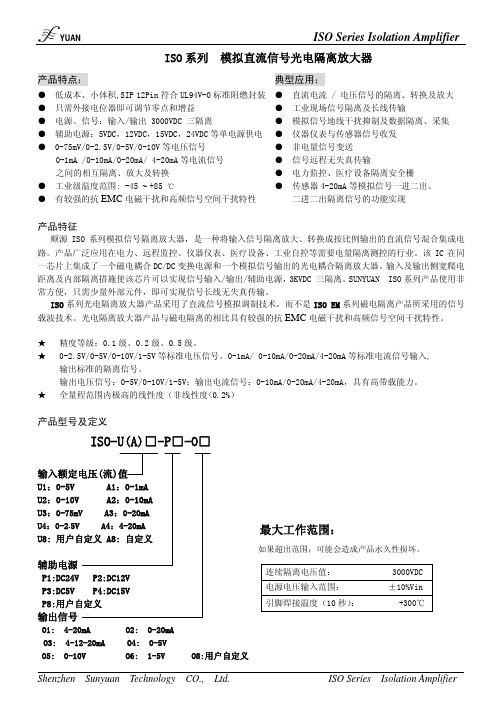
ISO 系列 模拟直流信号光电隔离放大器产品特点:典型应用:● 低成本、小体积,SIP 12Pin 符合UL94V-0标准阻燃封装 ● 只需外接电位器即可调节零点和增益● 电源、信号:输入/输出 3000VDC 三隔离● 辅助电源:5VDC,12VDC,15VDC,24VDC 等单电源供电● 0-75mV/0-2.5V/0-5V/0-10V 等电压信号0-1mA /0-10mA/0-20mA/ 4-20mA 等电流信号之间的相互隔离、放大及转换产品特征顺源ISO 系列模拟信号隔离放大器,是一种将输入信号隔离放大、转换成按比例输出的直流信号混合集成电路。
产品广泛应用在电力、远程监控、仪器仪表、医疗设备、工业自控等需要电量隔离测控的行业。
该IC 在同一芯片上集成了一个磁电耦合DC/DC 变换电源和一个模拟信号输出的光电耦合隔离放大器。
输入及输出侧宽爬电距离及内部隔离措施使该芯片可以实现信号输入/输出/辅助电源,3KVDC 三隔离。
SUNYUAN ISO 系列产品使用非常方便,只需少量外部元件,即可实现信号长线无失真传输。
ISO 系列光电隔离放大器产品采用了直流信号模拟调制技术,而不是ISO EM 系列磁电隔离产品所采用的信号载波技术。
光电隔离放大器产品与磁电隔离的相比具有较强的抗EMC 电磁干扰和高频信号空间干扰特性。
★ 精度等级:0.1级、0.2级、0.5级。
★ 0-2.5V/0-5V/0-10V/1-5V 等标准电压信号。
0-1mA/ 0-10mA/0-20mA/4-20mA 等标准电流信号输入, 输出标准的隔离信号。
输出电压信号:0-5V/0-10V/1-5V;输出电流信号:0-10mA/0-20mA/4-20mA,具有高带载能力。
★ 全量程范围内极高的线性度(非线性度<0.2%)产品型号及定义ISO-U(A)□-P□-O□输入额定电压(流)值U1:0-5V A1:0-1mA U2:0-10V A2:0-10mA U3:0-75mV A3:0-20mAU4:0-2.5V A4:4-20mA U8: 用户自定义 A8: 自定义辅助电源P1:DC24V P2:DC12VP3:DC5V P4:DC15VP8:用户自定义输出信号O1: 4-20mA O2: 0-20mAO3: 4-12-20mA O4: 0-5V O5: 0-10V O6: 1-5V O8:用户自定义● 工业级温度范围: -45 ~ +85 ℃● 有较强的抗EMC 电磁干扰和高频信号空间干扰特性● 直流电流 / 电压信号的隔离、转换及放大● 工业现场信号隔离及长线传输 ● 模拟信号地线干扰抑制及数据隔离、采集 ● 仪器仪表与传感器信号收发● 非电量信号变送 ● 信号远程无失真传输 ● 电力监控、医疗设备隔离安全栅 ● 传感器4-20mA 等模拟信号一进二出、 二进二出隔离信号的功能实现 连续隔离电压值: 3000VDC电源电压输入范围: ±10%Vin 引脚焊接温度(10秒): +300℃产品选型举例例1: 输入:0-5V 辅助电源:24V 输出: 4-20mA 产品型号: ISO-U1-P1-O1例2: 输入:4-20mA 辅助电源:24V 输出:4-20mA 产品型号: ISO-A4-P1-O1产品技术参数参数名称测试条件最小典型值最大单位隔离电压 1min 3000 VDC 增益1 V/V 增益温漂 100 ppm/℃ 非线性度 0.1 0.2 %FSR 电压 0 50 V 信号输入 电流0 30 mA 输入失调电压 2 5 mV 电压 0.3 1 M 输入阻抗 电流 250 Ω 电压 0 10 V 信号输出 电流0 20mA 电压 Vout=10V 2 * kΩ 负载能力 电流0 350 *Ω 频率响应-3DB 1 KHz 信号输出纹波 不滤波 10 20 mV RMS 信号电压温漂0.2 mV/℃ 电压 用户自定义 3.3 12 24 VDC 辅助电源 功耗 0.5 1 W 工作环境温度 -45 85 ℃ 贮存温度-55105℃* 备注:用户对产品电压信号或电流信号的输出带负载能力有要求的,可以按技术要求定制。
GNDRDBSDBSDARDAF...

目录第一章 产品概述.........................................................................................................................1 1.1 功能 ...............................................................................................................................1 1.2 一般规格 ........................................................................................................................1 1.3 各部分名称.....................................................................................................................2 1.4 外型尺寸及安装方法 ......................................................................................................4第二章 编辑软件 MD20...............................................................................................................5 2.1 MD20基本概述 ..............................................................................................................5 2.2 编辑用户画面 .................................................................................................................5 2.3 保存工程 ......................................................................................................................29 2.4 下载画面 ......................................................................................................................30 2.5 导入旧工程..................................................................................................................30第三章 操作方法.......................................................................................................................32 3.1 联机通讯 ......................................................................................................................32 3.2 切换画面 ......................................................................................................................32 3.3 系统口令 ......................................................................................................................32 3.4 修改数据 ......................................................................................................................33 3.5 开关量控制...................................................................................................................34第四章 与 PLC 的连接方法 .......................................................................................................35 4.1 三菱 FX 系列 ................................................................................................................35 4.2 西门子 S7-200 系列 .....................................................................................................36 4.3 欧姆龙 C 系列 ..............................................................................................................36 4.4 OMRON CP1H 系列 ............................................................................................................... 37 4.5 施耐德 NEZA/TWIDO 系列 ..........................................................................................39 4.6 台达 DVP 系列 ............................................................................................................40 4.7 松下 FP 系列 ................................................................................................................40 4.8 LG Master-K CNet 系列 ...............................................................................................41 4.9 LG 系列 Modbus 协议 ................................................................................................42 4.10 LG Master-K 120S 编程口通讯 .................................................................................43 4.11 FACON 永宏系列 .......................................................................................................43 4. 12 光洋 S 系列 ..............................................................................................................44 4.13 ECOSTEP 系列 ........................................................................................................45 4.14 AB Micrologix 系列.....................................................................................................46 4.15 MODBUS RTU/ASCII/EMERSON/RTU EXTEND .....................................................47 4.16 MODBUS SERVER ...................................................................................................48 4.17 自由协议 ........................................................................................................49 4.18 SAIA PCD S-BUS 协议 ..............................................................................................50 4.19 VIGOR PLC...............................................................................................................51 4.20 EMERSON EC20 系列 PLC ......................................................................................51Created with novaPDF Printer (). Please register to remove this message.文本显示器MD204L V4 用户手册4.21 KEYENCE KV 系列 PLC............................................................................................52 4.22 KEYENCE KV 系列 PLC...................................................................... 错误!未定义书签。
PA620-L3光纤纵差保护装置技术使用说明书V1.2
*本说明书有可能被更改,请关注最新版本。
敬请访问 参阅更多产品信息
INT 南京因泰莱电器股份有限公司
PA620-P 备用电源自投装置
目录
1 装置简介.....................................................................................................................................1 1.1 应用范围.........................................................................................................................1 1.2 主要功能和特点.............................................................................................................1 技术参数.....................................................................................................................................2 2.1 机械及环境参数.............................................................................................................2 2.2 额定电气参数................................................
汽车应用的限流可调、高效降压型DC-DC转换器(SD45216的数据手册)说明书
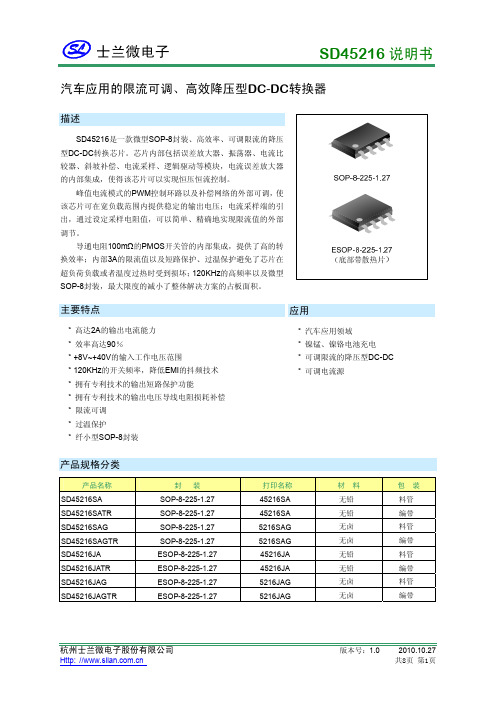
汽车应用的限流可调、高效降压型DC-DC转换器汽车应用领域镍锰、镍铬电池充电可调限流的降压型DC-DC可调电流源材料无铅45216SA45216SA 无铅5216SAG 无卤无卤45216JA 无铅45216JA5216JAG内部框图Q电压误差放大器+放大器R2=25参 数参 数 范 围输入端工作电压范围 +44 V -1 ~ +44+3 V+3 V 充电指示开漏输出端电压电气参数(除非特别注明,否则T amb =25°C ,V IN =12V ,V OUT =5V ,负载电流为0)参 数符 号 测 试 条 件最小值典型值 最大值单位输入电压范围 V IN V IN 端电压 8 -- 40 V 反馈端基准电压 V FB0.8150.835 0.855 V反馈端电流I FB V FB =0.81V -0.1 μA静态电流(无开关状态)I switch offV FB =1V3 mA管脚名称1 1 VIN P 芯片的电压输入端。
2 2 COMP I/O 补偿端,外接电阻电容网络。
3 3 GND G地。
4 4 FB I输出电压反馈输入端。
5 5 CS- I 6 6 CS+ I 电流采样的输入端,部电阻接于该两端之间。
7 7 CHRG O 充电状态指示的开漏输出端。
8 8 SW O 开关端。
EPExposedPAD散热片,接开关端。
功能描述SD45216是一款外部可调限流的降压型DC-DC转换器,电流采样管脚的引出,通过板子上的采样电阻,可以简单准确的调节限流值的大小。
恒流控制可以用来对镍锰、镍铬电池充电;也可用来作为一个带有可调限流值的标准降压DC-DC转换器。
典型导通电阻100mΩ的内部PMOS功率管,提高了转换效率,即使在大负载电流的情形下,也能维持较小的压降;内部3A的峰值限流,避免的芯片在负载过大等极端情况下受到损坏;当输出过载或者短路时,开关被关断,限制提供至输出端的电流大小,从而使负载以及芯片本身受到保护。
士兰微电子 AC-DC 产品简介

典型应用图
N
EMI FILTER
AC IN
L
DC OUT
SDH682X
新产品
1 GND 2 VCC 3 FB 4 BO
Drain Drain Drain HV
8 7 6 5集成MOS 电流检测电阻Silan 士兰微电子
内部框图
交叉式频率抖动,具有 自己的专利,改善EMI 集成可关断恒流源, 减小待机功耗,独 特工艺专利.
Silan 士兰微电子
SDH682X系列
SDH6823A 5V 2.1A 适配器
主要特色 demo外观
低待机功耗(230VAc, 25mW) 平均效率80%,满足EPA2.0标准 仅有一个差模电感 实现B/O功能,宽范围电压恒功率限制 100KHz频率,整机体积小 各种异常保护发生时自动重启 通过了各种安规测试( EMI, surge, ESD等)
Silan 士兰微电子
Part No. SD6861 SD6863 SD6864 SD6865 10W 14W 20W 26W 190V-265V Adapter Open Frame 14W 19W 24W 30W Adapter 8W 12W 18W 24W 85V-265V
SD686X系列
Ron 9.6 4.0 2.8 1.1 Ipeak 0.75 1.2 1.5 2.2
AC-DC产品和典型应用
Silan 士兰微电子
AC-DC 产品分布和应用
Silan AC/DC Product Profile & EE Applications
Applications Note
- 1、下载文档前请自行甄别文档内容的完整性,平台不提供额外的编辑、内容补充、找答案等附加服务。
- 2、"仅部分预览"的文档,不可在线预览部分如存在完整性等问题,可反馈申请退款(可完整预览的文档不适用该条件!)。
- 3、如文档侵犯您的权益,请联系客服反馈,我们会尽快为您处理(人工客服工作时间:9:00-18:30)。
Everlight Electronics Co., Ltd. http:\\ Rev 1.1 Page: 1 of 7
Technical Data Sheet
3mm Silicon PIN Photodiode T-1
PD204-6C/L3
Features
․Fast response time ․High photo sensitivity ․Small junction capacitance ․Pb free
Descriptions
PD204-6C/L3 is a high speed and high sensitive PIN photodiode in a standard 3Φplastic package. Due to its
water clear epoxy the device is sensitive to visible and infrared radiation.
Applications
․Automatic door sensor ․Camera
․Game machine
․High speed photo detector
Device Selection Guide Chip
LED Part No.
Material
Lens Color
PD Silicon Water clear
PD204-6C/L3
Absolute Maximum Ratings (Ta=25℃)
Parameter Symbol Rating
Units Reverse Voltage V R 32 V
Operating Temperature T opr-25 ~ +85 ℃
Storage Temperature T stg-40 ~ +85 ℃
Soldering Temperature T sol 260 ℃
P c 150 mW
Power Dissipation at(or below)
25℃Free Air Temperature
Notes: *1:Soldering time≦5 seconds.
Everlight Electronics Co., Ltd. http:\\ Rev 1.1 Page: 2 of 7
Everlight Electronics Co., Ltd. http:\\ Rev 1.1 Page: 3 of 7
PD204-6C/L3
Electro-Optical Characteristics (Ta=25℃)
Parameter Symbol Condition Min Typ Max Unit
Rang Of Spectral Bandwidth λ0.5 --- 400 --- 1100nm Wavelength Of Peak Sensitivity λP --- --- 940 --- nm Open-Circuit Voltage V OC Ee=5mW/cm 2
λp=940nm --- 0.44 --- V Short- Circuit Current I SC Ee=1mW/cm 2 λp=940nm --- 10 --- μA Reverse Light Current I L Ee=1mW/cm 2 λp=940nm V R =5V --- 10 --- μA Reverse Dark Current
I D
Ee=0mW/cm 2
V R =10V --- --- 10 nA
Reverse Breakdown Voltage B VR Ee=0mW/cm 2 I R =100μA 32 170 --- V
Total Capacitance C t Ee=0mW/cm 2
V R =5V f=1MHz
--- 10 --- pF
Rise Time t r --- 10 --- Fall Time
t f V R =10V
R L =100Ω
--- 10 ---
nS
Everlight Electronics Co., Ltd. http:\\ Rev 1.1 Page: 5 of 7
PD204-6C/L3
Reliability Test Item And Condition
The reliability of products shall be satisfied with items listed below.
Confidence level:90%
Everlight Electronics Co., Ltd. http:\\ Rev 1.1 Page: 6 of 7。
