OK国际推出全新的MRS-1000系统升级版
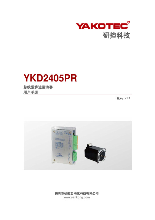
研控科技 YKD2405PR 总线型步进驱动器 用户手册说明书
目录前言 (1)1概述 (2)1.1产品介绍 (2)1.2特性 (2)1.3应用领域 (2)1.4产品命名规则 (3)2性能指标 (4)2.1电气特性 (4)2.2使用环境 (4)3安装 (5)3.1安装尺寸 (5)3.2安装方法 (5)4 驱动器端口与接线 (6)4.1接线示意图 (6)4.2端口定义 (7)4.2.1状态指示灯 (7)4.2.2控制信号输入/输出端口 (7)4.2.3电源输入/电机输出端口 (8)4.2.4拨码开关 (8)4.2.5 MODBUS总线端口 (8)4.3输入/输出端口操作 (8)4.4拨码开关设定 (10)4.5 RS485通讯端口 (12)5适配电机 (13)5.1电机尺寸 (13)5.2技术参数 (13)5.3电机接线图 (14)6 MODBUS通讯协议 (15)6.1 MODBUS寄存器地址定义 (15)6.2 MODBUS常用功能码 (21)6.2.1读保持寄存器命令03 (21)6.2.2写单个寄存器命令06 (22)6.2.3写多个寄存器命令16 (22)6.2.4通讯错误码 (23)6.2.5应用示例 (24)7运动控制功能介绍 (26)7.1位置模式 (26)7.2速度模式 (27)7.3多段位置模式 (27)7.3.1 位置段参数介绍 (27)7.3.2 多段位控制方式 (28)7.4多段速度模式 (29)7.4.1 速度段参数介绍 (29)7.4.2 多段速度控制方式 (29)7.5回原点功能 (30)7.6运动控制命令 (31)7.6.1 启动命令(0x0027) (31)7.6.2 停止命令(0x0028) (31)7.6.3 回原点命令(0x0030) (32)8报警排除 (33)9版本修订历史 (34)10保修及售后服务 (35)10.1保修 (35)10.2售后服务 (35)前言感谢您使用本公司总线型步进驱动器。
在使用本产品前,请务必仔细阅读本手册,了解必要的安全信息、注意事项以及操作方法等。
卡伦三代管理系统说明书
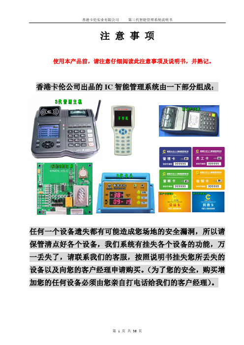
注意事项使用本产品前,请注意仔细阅读此注意事项及说明书,并熟记。
香港卡伦公司出品的IC智能管理系统由一下部分组成:任何一个设备遗失都有可能造成您场地的安全漏洞,所以请保管清点好各个设备,我们系统有挂失各个设备的功能,万一丢失了,请联系我们的客服,按照说明书挂失您所丢失的设备以及向您的客户经理申请购买。
(为了您的安全,购买增加您的任何设备必须由您亲自打电话给我们的客户经理)。
主机操作说明主机开机后显示欢迎界面,左侧显示的是全球唯一卡伦游艺厅编码一、收银员操作:主键盘付键盘功能键:<F1>为存入状态、<F2>为取出状态、<F3>为卡取币状态、<F4>为现金售币状态、<条码>为小票取币、按<功能>键可以让客人输入密码或用户标识信息,按<主菜单>可以调出其他菜单。
1、插入收银卡(芯片面朝下),此时界面上会显示此收银卡的工号,在密码框输入收银员密码,按确定进入收银界面:2、放上用户卡显示卡号和余数。
这时只要输入充值金额,按确定。
我们主机会自动算出充值数充入卡中,余数显示正确后听到“嘟”一声,充值成功。
(下方提示总存总取等是指,本会员卡持卡人使用的总存和总取)3、按功能键<F2>,进入了取出状态,放上用户卡后显示卡号和余额,并且在输入框里面自动计算出金额,如果是全部取出,那直接按确定键,如果取出一部分,那直接输入取出值后按确定。
5、按<F3>,进入取币操作界面,此时放上用户卡,显示卡号与余额,此时只要输入需要取出的币数就可以直接从售币机里打出所取币数。
6、按<F4>,进入售币操作界面,此时就可以收现金,键入金额就可以售出所需的币数。
7、按条码键进入条码扫描出币状态,此时用条码枪扫描卡伦存币机打印的小票进行取币操作。
8、放上客人卡后显示卡号和余额,这时按功能键会弹出一个修改用户密码的窗口,此时用户可以修改自己的使用密码。
斯耐克森 数字社区可视对讲门口主机 SNX-IPX-D11系列 IPX单摄像头门口主机 使用说明书
数字社区可视对讲门口主机使用说明书V1.3型号:SNX-IPX-D11系列SNX-IPX-D12系列SNX-IPX-D17系列SNX-IPX-D18系列SNX-IPX-D19系列SNX-IPX-D28系列SNX-IPX-D29系列SNX-IPX-D33系列目录产品简介: (2)基本功能介绍: (2)基本功能操作说明: (4)工程设置操作说明: (5)安装注意事项: (7)技术参数: (8)故障排查: (8)安全注意事项: (8)谢谢您使用斯耐克森数字智慧社区楼宇对讲系统的产品,使用前请详细阅读本手册。
请妥善保管本手册,以备日后参考。
由于技术的不断更新,手册中可能会于实际操作有不符之处,其最终解释权归本公司所有。
产品简介:可视对讲门口主机产品采用嵌入式安装设计,可以安装在单元入口作为单元门口主机,也可以安装在小区入口作为围墙门主机使用。
通过使用键盘拨号可以呼叫小区住户可视对讲分机,或者呼叫小区保安分机及管理中心电脑平台。
在核实来访者身份后,业主或者小区管理人员可以远程控制打开连接在门口机上的电控锁或者磁力锁。
除此之外,门口主机还有多种开锁方式,比如:密码开锁,刷卡开锁等等。
这些开门方式的操作说明都显示在门口主机的显示屏上供用户参考。
基本功能介绍:1.访客可视对讲:1.1门口主机可输入业主房号呼叫业主的室内机,进行可视对讲。
2.求助功能:2.1门口机可呼叫保安亭或者物业中心进行求助和咨询。
3.门禁开锁功能:3.1门口机可密码开锁。
3.2IC卡刷卡开锁。
3.3访客呼叫业主室内机,室内可远程开锁,打开本地门禁电控锁。
3.4求助保安亭或者物业中心开锁。
4.视频监控功能:4.1业主可通过室内机来监控单元门的图像,并可拍照保存。
4.2保安亭和物业中心可通过远程监控,来查看当前门口机的监控情况。
5.呼叫电梯功能:5.1门口机开锁的同时,呼叫电梯到1层。
5.2住户用刷卡开锁,密码开锁等开锁方式开锁后,打开住户对应楼层的电梯权限。
ViHome 客户端安装使用 说明书

3.1 家居管理
点击手机菜单,在弹出的界面中 选择“系统设置”,单击选择设备管 理,在屏幕下方可出现楼层、房间、 情景、设备、定时五种选项。如右 图所示:
3.1.1 楼层管理
请单击点击手机菜单, 在弹出的界面中选择系统 设置设备管理 > 楼层,进 入楼层管理界面。
若需添加新楼层,请 在楼层管理界面选择添加 楼层,在添加楼层界面输 入楼层名称,点击“添加” 添加成功;
电话:0755-83256376
网址:
ViHome 最具性价比的智能家居系统
若需修改楼层, 请在楼层管理界面 选择需要修改的楼 层,点击编辑,编 辑楼层信息完成后, 点击“确定”编辑 成功;
家模式”点击“说完了”即可执行“回家模式”
操作,若想返回点击“取消”。目前此版本的语
音识别只支持中文,所以在给设备命名时请尽
量使用中文。
电话:0755-83256376
网址:
ViHome 最具性价比的智能家居系统
3.家居管理
物联智慧 创意生活
点击手机菜单,在弹出的界面中选择“系统设置”。
注意:在远程登录后,不能添加、删除、编辑任何设备,只能对设备进 行远程操控。
电话:0755-83256376
网址:
ViHome 最具性价比的智能家居系统
2.客户端主界面 登录后客户端主界面如图所示:
物联智慧 创意生活
语音控制
:
点击此图标可弹出如右图对话框,您需要
在弹出对话框后说出你要进行的操作,如“回
二、产品功能 ² 普通灯光控制 ² 插座控制 ² 调光灯控制 ² RGB 灯控制 ² 空调控制 ² 窗帘控制 ² 家庭影院控制 ² 安防监控 ² 语音控制
电话:0755-83256376
录播MRS解决方案
创视通MRS多媒体会议录播解决方案需求概述用户有12间多媒体会议室音视频、电脑信号需要录制,多媒体会议室已有完整的扩声及视频显示系统,现场信号需要能被录制下来,供PC用户点播。
方案部署根据现在网络结构情况,在网络中心机房配置1台TRS录播服务器,7个标清多媒体会议室各配置一台avx1000,进行音视频及vga电脑信号的录制。
视频输入接口接一路摄像头。
一路音频输入分别接功放或者调音台的声音输入。
Vga 的信号的输入,最大支持到1600x1280分辨率输入,一般的1024x768分辨率可以到25帧。
5个高清多媒体会议室各配置两台avx3000,一台进行音视频及vga电脑信号的录制。
视频输入接口接一路摄像头。
一路音频输入分别接功放或者调音台的声音输入。
一台进行VGA的录制。
方案解析架构非常合理:全部的数据交换是在网络中心机房进行,因此可以满足大容量的点播和直播需求,而且因为中心机房可以7x24小时开机器,所以可以满足7x24小时的点播和直播。
使用非常简单:每个会议室放置的A VX,因为是dsp设计,完全不需要风扇,完全没有噪音。
而且因为不是电脑插卡的方式,因此开机即用,也没有防病毒的烦恼。
功能丰富:除了可以大量的进行开会过程的录制,还可以做为领导对下属开会情况的考评。
高性价比:因为采用了分布式的结构,因此每个会议室只需要配置A VX核心设备,而其他的辅助设备都是可选件,因此成本相对非分布式架构的录播系统来说,相差很大。
系统效果图系统结构图(高清)一、录制二、播放系统结构图(标清)系统配置系统功能描述MRS 3000多媒体录播广播视频系统:●同步录制同步录制视频、音频,计算机动态屏幕,即可将主讲人的图像、声音和所讲解的课件、讲稿、鼠标操作轨迹以及电子白板上书写的内容等计算机屏幕上所显示的内容同步录制到一个文件中。
●实时直播和组播可通过单播或组方式将现场的视频、音频、计算机动态屏幕在网络上进行实时直播,用户可通过IE浏览器同步接收到现场的视频、音频和计算机动态屏幕信息。
AP1000

(2)简化的非能动设计提高安全性和经济性
AP1000主要安全系统,如余热排出系统、安注系统、安全壳冷却系统等,均采用非能动设计,系统简单,不 依赖交流电源,无需能动设备即可长期保持核电站安全,非能动式冷却显著提高安全壳的可靠性。安全裕度大。 针对严重事故的设计可将损坏的堆芯保持在压力容器内,避免放射性释放。
AP1000
美国西屋公司开发的产品
01 历史
03 第3代
目录
02 设计规范 04 发展历程
美国西屋公司在已开发的非能动先进压水堆AP600的基础上开发了AP1000。AP1000是Advanced Passive PWR的简称,1000为其功率水平(百万千瓦级),该堆型为西屋公司设计的3代核电堆型。
2009年3月31日14时06分,世界上首台AP1000核电机组三门核电站一号机组核岛第一罐混凝土浇注顺利完成, 4月20日混凝土养护取得成功。这是世界核电站工程建设中首次成功采用核岛筏基大体积混凝土一次性整体浇注 的先进技术,中国成为首个成功掌握此项技术的国家。核电站核岛筏基是核反应堆厂房的基础部分,其大体积混 凝土一次性整体浇注,可以实现核电站核岛基础的一次整体成形,具有无接口、防渗好等技术优点,特别适合安 全性能要求较高的核电施工。但由于浇注后的养护是难点,一直是施工的一大技术难题。该项技术的成功实施, 可以有效缩短工期,将为未来第三代核电的批量化建设带来巨大的经济价值。
TeamPoS 2000 版本 1.0 升级至 M 母板安装指南说明书

Team PoS2000® Installation Instructions Upgrade to M MotherboardFujitsu Transaction Solutions Inc. endeavors to ensure that the information in this document is correct and fairly stated but does not accept liability for any error or omission. For safety and regulatory information see the TeamPoS 2000 Installation & Maintenance Manual (PIN #90000291).The development of Fujitsu products and services is continuous and published information may not be up to date. It is important to check the current position with Fujitsu Transaction Solutions Inc. This document is not part of a contract or license save insofar as may be expressly agreed.This document was originally issued October 1, 2004.Hardware Differences: The new M motherboad differs from the older H and A motherboards in the following ways:o CPU o LANo Chipsets o USBo Memory o Video Controllero Drivers o HeatsinkThe most notable differences are the CPU and chipsets, The A & H motherboards utilize Intel’s 440BX chipset, whereas the newer M motherboard uses Intel’s 855GME chipset.“A” or “H” Pentium III Motherboard (90000153 or 90000459)“M” motherboard (90000759)Operating System Differences: Windows2000 Pro and Windows XP Pro disk images installed on and built for previous motherboards will not function on M motherboard systems. If attempted, results will vary from BSOD (bad sector on disk) experiences to repetitive reboot scenarios.Fresh Windows2000 Pro and XP Pro images targeted to the M motheraboad must be acquired from Fujitsu Transaction Solutions Inc., or installed from Windows release media. Once the Windows platform is installed and system drivers for M motherboard devices configured, applications can be ported to the platform and system can be tested. After installing a fresh Windows build on the new system, M motherboard device drivers and instructions for loading them can be acquired from/fujitsutemp.asp?navid=47 or from your Fujitsu Transaction Solutions Inc technical Sales Support team representative.TeamPoS 2000 I/O boards and POS peripherals remain unchanged between M motherboard and previous motherboards so the porting activity should consist of properTP2K slice configuration and testing.Lab Testing: It goes without saying that applications should be thoroughly system tested on the new platform prior to installing it in any store. CPU and bus speeds are significantly increased with the M motherboard so timing based routines could be impacted.The current release set of M motherboard hardware is as follows:Base Motherboard Chipset Intel 855GMEVideo Intel Shingle Springs drivers for FujitsuLAN Adapter Intel 82562ET Pro/100 VE NetworkConnectionAudio RealTek AC’97 AudioInstallation Checklist with Time EstimatesEstimate Process Time1. Install CPU and heatsink on Pentium M (See page xx) 10 minutes2. Install memory (no instructions required) 1 minute3. Remove the old motherboard and set aside. (See page xx) 5 minutes4. Install new motherboard and attach peripherals (no5 minutesinstructions required)60 minutes*5. Load Windows 2000 or XP Pro (follow Microsoftinstructions6. Load Windows 2000 or XP Devices/Drivers**30 minutesa. Windows 2000 Driver Installationb. Windows XP Driver Installation7. BIOS check – for customers using custom BIOS settingsonly.* Time estimate based on loading from CD** See web page /fujitsutemp.asp?navid=47Preparing the motherboard – CPU and Heatsink Installation:Installing the CPU & Heatsink1. Place the M motherboard on a clean flat surface.2.Install the CPU into the socket making sure that the CPU slides all the way into the socket.3.Turn CPU socket locking screw ¼ turn clockwise to lock in the CPU (see picture on page 2).4. Mount new retention bracket on back side of motherboard5. Rotate heatsink so that the vents are running parallel to the memory sticks (for correct airflow from the chassis fan and CPU fan over the heatsink).6. Remove protective cover over heatsink compound and mount heatsink on CPU making sure it is flush against the CPU and the vents are pointing in the right direction.7. Screw in the four mounting screws by first screwing in two screws in opposite corners. Do the same for the remaining two screws. Screws will come to a stop when bottoming out on retention bracket.8.Plug in the CPU fan and reinsert motherboard.VentalignmentMemory alignmentInstallation – Removing the old and installing the new motherboardThis section shows how to access the control unit components to add or change configurations. Accessing the TeamPoS2000 internal components always requires the removal of the front panel.1.Push the upper center (three raised dots) of the front cover to open it. An optionalkey lock is available for front cover (not shown here).2.Manually loosen the two metal thumbscrews on the right and left to remove theentire front cover. A coin or screwdriver can be used to loosen the thumbscrews if they are too tight.3.While facing the front of the device, first pull the left side cover slightly forward(in the direction indicated by the arrow) to remove the side cover.3.To mount the side cover again, first insert the tab at the lower back of the coverinto the hole in the cabinet, insert the remaining tabs, and then slide cover to the rear.4.Remove all cables from the back of the motherboard and unplug the AC power5. Remove the motherboard by sliding the lever arm toward you on the side access panel6. To install a new motherboard reverse this procedure. Use the lever arm to completely seat the new motherboard. If the new motherboard is not seated properly, boot up issues may arise.。
安全隔离与信息交换系统技术说明书
延续,如何解决安全与应用之间的矛盾?应用的需要和安全的需要催生了一种新型的技术,
物理隔离技术(GAP)。这种技术在 1993 年由 Myong H.Kang 在“A Pump for Rapid, Reliable,
Secure Communication”一文中提出,并在 1996 年对这种概念进一步深化为一种适于网络应
5.1.1. 静态文件单向传输..........................................................................15 5.1.2. 数据库单向同步..............................................................................18 5.1.3. 网页单向发布..................................................................................19 5.1.4. 邮件单向中继..................................................................................19 5.2. 产品对比.................................................................................................20
2.1. 概述...........................................................................................................4 2.2. 体系结构...................................................................................................4 2.3. 功能指标...................................................................................................6 3. 产品功能描述.........................................................................................................7 3.1 信息单向传输功能...........................................................................................7 3.2 安全控制功能...................................................................................................9 3.3 系统监控与审计功能.....................................................................................10 4. 技术特点............................................................................................................... 11 4.1. 单向数据通道......................................................................................... 11 4.2. 数据封装及传输.....................................................................................12 4.3. 协议终止.................................................................................................13 4.4. 数据容错处理.........................................................................................14 5. 产品使用方式.......................................................................................................15 5.1. 产品应用范围.........................................................................................15
SIMATIC IPC547J SIMATIC 工业 PC SIMATIC IPC547J 操作说明
C
法律资讯
警告提示系统
为了您的人身安全以及避免财产损失,必须注意本手册中的提示。人身安全的提示用一个警告三角表示,仅 与财产损失有关的提示不带警告三角。警告提示根据危险等级由高到低如下表示。
危险 表示如果不采取相应的小心措施,将会导致死亡或者严重的人身伤害。
警告 表示如果不采取相应的小心措施,可能导致死亡或者严重的人身伤害。
Siemens AG Digital Industries Postfach 48 48 90026 NÜRNBERG 德国
A5E45911111-AB Ⓟ 09/2021 本公司保留更改的权利
Copyright © Siemens AG 2021. 保留所有权利
前言
本操作说明的用途 本操作说明包含 SIMATIC IPC547J 安装、电气连接、调试和扩展以及维护和维修设备所需 的全部信息。本操作说明是专为以下具有资质的专业人员编写的: • 装配工 • 调试工程师 • IT 管理员 • 维修与维护人员
SIMATIC IPC547J
SIMATIC 工业 PC SIMATIC IPC547J
操作说明
09/2021
A5E45911111-AB
前言
产品说明
1
安全须知
2
安装和连接设备
3
调试设备
4
操作设备
5
扩展设备并为其分配参数
6
设备维护和维修
7
技术规范
8
尺寸图
9
标准和认证
10
硬件说明
A
技术支持
B
标志和符号
小心 表示如果不采取相应的小心措施,可能导致轻微的人身伤害。
பைடு நூலகம்注意
【MD培训课件1】滚筒新爱尚系列

1、蒸汽洗涤
➢ 顾客利益点:
更干净 就像人美容一样,用蒸汽打开人体面部的毛孔,彻底清除毛 孔内的脏污。高温蒸汽深层渗透衣物的纤维,软化污渍,强化洗涤 效果。
更健康 高温有效减少衣物上的细菌 更清新 高温水蒸汽喷洒在衣物上,可清除衣物上的异味,洗过的衣
物没有刺鼻的洗涤剂味道,闻起来更清爽。 更舒展 高温蒸汽洗涤不伤衣物,在筒内均匀释放蒸汽,洗过的衣物
洗涤时间、漂洗次数、脱水时间、洗涤温度、脱水转速都可调
16
4、集成洗护程序
➢ 记忆洗——真正懂你洗衣机习惯的洗衣机 记忆洗为上一次洗涤的程序设定。即本次设定的洗涤 过程,洗衣机自动记忆。下次开机选择记忆洗时,自 动显示为上次的洗涤设定
17
三、美的新爱尚辅助核心功能
美的新爱尚辅助核心功能介绍: 1、中途添衣; 2、一件衣服也能甩; 3、特色程序; 4、人性化设计; 5、雅智外观
18
1、中途添衣
➢ 特设中途添衣功能键,能够即时开门,再也不怕遗忘衣物, 中途可以随时添衣,洗衣更方便。
➢ 采用德国进口EMZ电子门锁,平常洗涤状态下选择中途 添衣,开门只需1秒钟;进排水和脱水时选择中途添衣, 停止进排水或脱水加上开门时间,不超过3秒钟。令衣物 可以更快、更方便的添加或取出,洗涤更加方便。
更舒展、更柔软、更蓬松,不用熨烫都能穿。
7
2、智能烘干,衣干即停
➢ 技术原理: 爱尚烘干技术采用冷凝式烘干。风机鼓风, 通过加热管加热,热空气被股入筒中开始 烘干,筒内湿热的空气通过冷凝装置预热 变成小水珠,通过排水管排出。被干燥冷 却的空气继续回到风机进行下一个循环。 (在烘干过程中,进水阀一直打开,保证 冷凝管中冷水储备)
冷凝
直排
9
2、智能烘干,衣干即停
Pepperl+Fuchs 1000系列快速交换烟道系统说明说明书
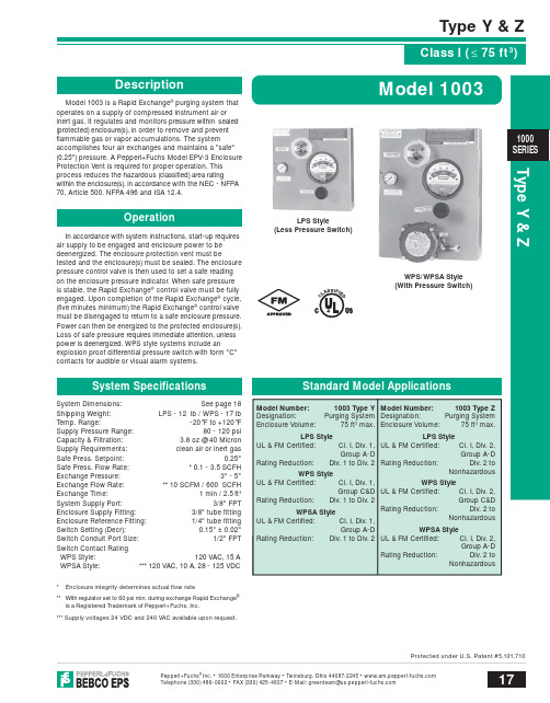
Type Y & ZType Y & Z17Pepperl+Fuchs ® Inc. • 1600 Enterprise Parkway • Twinsburg, Ohio 44087-2245 • Telephone(330)486-0002•FAX(330)425-4607•E-Mail:**************************.comProtected under U.S. Patent #5,101,7101000SERIESModel 1003 is a Rapid Exchange ® purging system that operates on a supply of compressed instrument air or inert gas. It regulates and monitors pressure within sealed (protected) enclosure(s), in order to remove and prevent fl ammable gas or vapor accumulations. The systemaccomplishes four air exchanges and maintains a "safe" (0.25") pressure. A Pepperl+Fuchs Model EPV-3 Enclosure Protection Vent is required for proper operation. This process reduces the hazardous (classifi ed) area ratingwithin the enclosure(s), in accordance with the NEC - NFPA 70, Article 500, NFPA 496 and ISA 12.4.In accordance with system instructions, start-up requires air supply to be engaged and enclosure power to be deenergized. The enclosure protection vent must betested and the enclosure(s) must be sealed. The enclosure pressure control valve is then used to set a safe reading on the enclosure pressure indicator. When safe pressure is stable, the Rapid Exchange ® control valve must be fully engaged. Upon completion of the Rapid Exchange ® cycle, (fi ve minutes minimum) the Rapid Exchange ® control valve must be disengaged to return to a safe enclosure pressure. Power can then be energized to the protected enclosure(s). Loss of safe pressure requires immediate attention, unless power is deenergized. WPS style systems include anexplosion proof differential pressure switch with form "C" contacts for audible or visual alarm systems.System Dimensions: See page 18Shipping Weight: LPS - 12 lb / WPS - 17 lb Temp. Range: -20°F to +120°F Supply Pressure Range: 80 - 120 psi Capacity & Filtration: 3.8 oz @ 40 Micron Supply Requirements: clean air or inert gas Safe Press. Setpoint: 0.25"Safe Press. Flow Rate: * 0.1 - 3.5 SCFH Exchange Pressure: 3" - 5" Exchange Flow Rate: ** 10 SCFM / 600 SCFH Exchange Time: 1 min / 2.5 ft 3System Supply Port: 3/8" FPT Enclosure Supply Fitting: 3/8" tube fi tting Enclosure Reference Fitting: 1/4" tube fi tting Switch Setting (Decr): 0.15" ± 0.02"Switch Conduit Port Size: 1/2" FPT Switch Contact Rating WPS Style: 120 VAC, 15 A WPSA Style: *** 120 VAC, 10 A, 28 - 125 VDC* Enclosure integrity determines actual fl ow rate** With regulator set to 60 psi min. during exchange Rapid Exchange ® is a Registered Trademark of Pepperl+Fuchs, Inc.*** Supply voltages 24 VDC and 240 VAC available upon request.LPS Style(Less Pressure Switch)3WPS/WPSA Style (With Pressure Switch)Type Y & Z18Pepperl+Fuchs ® Inc. • 1600 Enterprise Parkway • Twinsburg, Ohio 44087-2245 • Telephone(330)486-0002•FAX(330)425-4607•E-Mail:**************************.comProtected under U.S. Patent #5,101,7101000Filter1003 - LPS - CI - YZ - LH - ##Series Model Number System Style LPS - less pressure switch WPS - with pressure switch WPSA - with pressure switch Area Classifi cation CI - Class I Area System Type YZ - Div. 1 to Div. 2, Div. 2 to Nonhazardous Mounting Confi guration LH - left hand left side of enclosure RH - right hand right side of enclosure TM - top mount top of enclosure BM - bottom mount bottom of enclosure WM - wall mount wall surface FM - frame mount external frame or rack PM - panel mount enclosure surface cutout (Not available in WPS Style )## - See Accessories Page 116 for additional factory installed accessoriesONE (1) ENCLOSURE WARNING NAMEPLATE & ONE (1) INSTALLATION & OPERATION MANUAL ARE PROVIDED WITH EACH SYSTEMMaterial Specifi cationsFilter Regulator Body: Zinc w/Enamel FinishRegulator Handle & Bowl: Polycarbonate Enclosure Pressure Gauge: Alum. w/Enamel Finish Rapid Exchange Gauge: Poly Case & Brass Tube Tube Fittings & Valves: 316 SS Forged Body Tubing: 316 SS 1/4" & 3/8" .035 Welded System Nameplates: Silk screened Lexan ® & SS Fastener Hardware: Alum. & Stainless Steel Mounting Plate: 316 14 Ga #3 Brush SS EXP Pressure Switch Body: Anodized Cast Alum.Enclosure Warning Nameplate: Silk screened SSLexan ® is a registered trademark of the General Electric CompanySupply Outlet PlateSystem Supply Inlet Rapid ®Venturi Orifi ce Gauge Inlet WPS/WPSA Style (With Pressure Switch)CONNECTION FITTINGSNC-6 3/8" Ninety Connector SC-6 3/8" Straight Connector EFC-4 1/4" Flush Connector EFC-6 3/8" Flush Connector EBC-6 3/8" Bulkhead ConnectorEPC-13 1" Pipe ConnectorADDITIONAL ITEMSSMK-2 or -8 System Mounting Kit EPSK-1Explosion Proof Switch KitGPSK-1 General Purpose Switch KitRAH Remote Alarm HornRAB-1 Div. 1 Remote Alarm Beacon RAB-2 Div. 2 Remote Alarm BeaconLCK L Fitting Conduit Kit TCK T Fitting Conduit KitENCLOSURE PROTECTION VENTSONE VENT REQUIRED WITH EACH SYSTEMEPV-3-SA-00 Straight w/Spark Arrestor EPV-3-SA-90 Rt Angle w/Spark ArrestorWARNING NAMEPLATESEWN-1 Class I Enclosure Warning ETW Enclosure Temperature WarningINSTALLATION & OPERATION MANUAL129-0195Inst. & Operation ManualSMK-2EBC-6EFC-4CONNECTION POINTS SHOWN ABOVE IN BOLD TEXT ON SYSTEM DIAGRAM。
RIM-1000配置菜单访问指南说明书
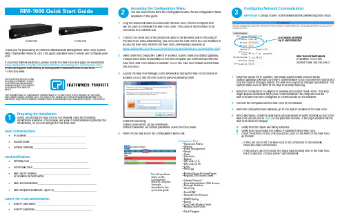
Accessing the Configuration MenuYou will select items from the Configuration Menu for all configuration tasks described in this guide.1 Plug the crossover cable (included with the RIM-1000) into the computer thatwill be used to configure the RIM-1000. Note: T his cable is not intended to beconnected to a network hub.2 Connect the other end of the crossover cable to the Ethernet port on the back ofthe RIM-1000. Note:Alternatively, you could use the RIM-1000’s EIA-232 interface to access the RIM-1000. Refer to the RIM-1000 User Manual (available at /Products/Environmental-Monitoring-and-Security/RIM-1000).3 Write down the computer’s current IP address, subnet mask and default gateway.Change these items temporarily so that the computer can communicate with the RIM-1000. RIM-1000 default IP address: 10.0.0.188. RIM-1000 default subnet mask: 255.255.255.0.4 Access the RIM-1000 through a web browser by typing the RIM-1000’s default IPaddress (10.0.0.188) into the location bar and pressing Enter.Enter the following:Default User Name: cpi (all lowercase)Default Password: No default password. Leave this field blank.5 From the top bar, select the Configuration Menu link.Configuring Network CommunicationIMPORTANT Consult your IT administrator before performing these steps.1 Enter the values for IP Address, Net Mask (subnet mask) and Def Route(default gateway) provided by your IT administrator. Once you enter the values and click the Submit Changes button, the RIM-1000 saves the changes and reboots. T he system status LED on front of the RIM-1000 stops flashing.2 Reset the computer to its original IP address and subnet mask. Note: T his stepmight require assistance from your IT administrator. T he computer and theRIM-1000 are now both configured to communicate on the network.3 Connect the computer and the RIM-1000 to the network.4 From the computer’s web browser, go to the new IP address of the RIM-1000.5 When prompted, enter the user name and password to verify network access to theRIM-1000 (as you did in step 4 in the previous section). If the login window for theRIM-1000 does not display:A Verify that the cables are firmly attached.B Verify that you entered the correct IP address for the RIM-1000.C Check for activity on the Link and Active LEDs on the front of the RIM-1000as follows:> If the Link LED is off, the RIM-1000 is not connected to the network. Check the cable connections. > If the Active LED is on solid, too much data is being sent to the RIM-1000 for it to process. Consult your IT administrator.Preparing for InstallationWhen connecting the RIM-1000 to the network, have the followinginformation available. If necessary, ask your IT administrator to provide this information, so you can assign it to the RIM-1000.Basic Communications• IP Address _______________________________________________• Subnet Mask _____________________________________________•Default Gateway __________________________________________Email Notifications• Primary DNS _______________________________________________• Secondary DNS _____________________________________________•Mail SMTP address __________________________________________(IP address or host name)• Mail sender address_______________________________________________•Mail recipient addresses (up to 8)__________________________________ESMTP (for e-mail authentication)• ESMTP user name _______________________________________________•ESMTP password _____________________________________________Thank you for purchasing the Remote Infrastructure Management (RIM-1000) System from Chatsworth Products (CPI). T his guide describes how to install and configure your unit.If you need further assistance, please access the RIM-1000 web page on our website /Products/Environmental-Monitoring-and-Security/RIM-1000/, ******************************************************************+1-800-834-4969.©2014 Chatsworth Products, Inc. All rights reserved. Chatsworth Products, CPI, CPI Passive Cooling, eConnect, MegaFrame, Saf-T-Grip, Seismic Frame, SlimFrame, TeraFrame, GlobalFrame, Cube-iT Plus, Evolution, OnTrac, QuadraRack and Velocity are federally registered trademarks of Chats-worth Products. Simply Efficient is a trademark of Chatsworth Products. All other trademarks belong to their respective companies. 7/14 MKT-60020-620While every effort has been made to ensure the accuracy of all information, CPI does not accept liability for any errors or omissions and reserves the right to change information and descriptions of listed services andproducts.* Y ou will use theseitems on the ConfigurationMenu to complete the tasksdescribed in thisquick start guide.Configuration Menu • Inputs and Relays * • System * • Alarm Management • T rends • Clock • Schedules • Battery • URL Links (1-5) • URL Links (6-10) • Links • Nest/Egg• Modem/Phone Number/Pagers • Keypad/DTMF Access Users • Internet Protocol *• User Administration (Web Access) • Network Statistics • Icmp Ping• Email/DNS *• Network T ime Protocol • SNMP/Syslog • Bacnet• Com Port1/Modbus/Telnet • Modbus Slave Units• Flash Program2U RIM-10001U RIM-1000123R IM-1000 Default Values IP address: 10.0.0.188Subnet mask: 255.255.255.0©2014 Chatsworth Products, Inc. All rights reserved. Chatsworth Products, CPI, CPI Passive Cooling, eConnect, MegaFrame, Saf-T-Grip, Seismic Frame, SlimFrame, TeraFrame, GlobalFrame, Cube-iT Plus, Evolution, OnTrac, QuadraRack and Velocity are federally registered trademarks of Chats-worth Products. Simply Efficient is a trademark of Chatsworth Products. All other trademarks belong to their respective companies. 7/14 MKT-60020-619While every effort has been made to ensure the accuracy of all information, CPI does not accept liability for any errors or omissions and reserves the right to change information and descriptions of listed services andproducts.Configuring the InputsThe eight non-isolated universal inputs are connected to T B2 and T B3. Universal input channels can be individually configured through the RIM-1000 to monitor a 4-20mA signal, a normally open (NO) dry contact relay or a normally closed (NC) dry contact relay.Making the Physical ConnectionsThe following figure shows examples of input wiring.Once you have wired the inputs, make note of the following:• Sensor type (analog or digital) connected to each channel.• For analog sensors, the high/low values.• For digital sensors, the non-alarm state - normally open (NO) or normally closed(NC).Configuring the ChannelsConfigure the input channels using the Inputs & Relays page of the RIM-1000 web inteface. Click on the underlined label for the input you want to configure.Configuring InputsA Input can be Analog 4-20 mA or Digital NO or NC.B Applies only to analog inputs. Gain and offsett determine the correct value for the RIM-1000.C Applies only to analog inputs. Hysteresis designates the amount an input must change before returning to normal.D Applies only to analog inputs. Displays units on main menu, such as Deg F , Deg C, %RH, Amps, Volts, psi, etc.E RIM-1000 current raw reading and calculated value.F Applies only to Analog inputs. High and Low alarm thresholds of range being monitored.G This label is displayed on the RIM-1000 menu and the configuration menu.HRelay configuration link.A B C DEHConfiguring System InformationA An alphanumeric name that you would recognize. T his name appears on the Main Menu and is included as part of email and pager notifications.B An integer greater than 5.C Consult your PDA manual for the correct width.D The number of points to be monitored. Maximum 104.AB CConfiguring Email NotificationThe RIM-1000 sends one email message per alarm instance to a maximum of eight email recipients.A Refer to information from IT administrator.B Text that is easily recognized as notification from the RIM-1000.C Up to eight email recipients.D For ESMTP email authentication. Refer to information from ITadministrator.CCompleting the InstallationOnce you have completed the tasks in this quick start guide, the RIM-1000 can communicate over the network and monitor the inputs you configured.Consult the RIM-1000 User Manual at /Products/Environmental-Monitoring-and-Security/RIM-1000 for information about completing these additional tasks:• System clock settings• Network time protocol settings • SNMP/Syslog settings • Modbus/Telnet settings • BACnet settings • User administration• URL links to IP-addressable devices• Nest/Egg configuration (for additional RIM-1000 appliances that will bemonitored by a central RIM-1000 appliance)• Trends• Alarm managementCommon 4Wire SensorsCommon 3Wire SensorsIE: CPI P/N 60111-001, 60111-002T emperature SensorIE: CPI P/N 60111-004/60111-005T emperature/Humidity SensorIE: CPI P/N 60110-001Power Fail MonitorIE: Common Ground forUPSIE: CPI P/N 60109-001,Spot Detector4567。
英语M ASTRO APX 1000系列数码无线电对话器快速参考卡说明书
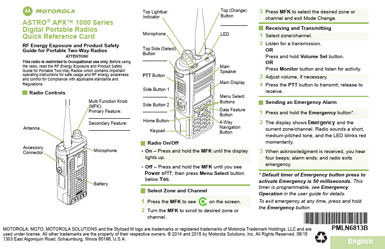
EnglishmASTRO ® APX™ 1000 Series Digital Portable Radios Quick Reference CardRF Energy Exposure and Product Safety Guide for Portable Two-Way RadiosATTENTION!This radio is restricted to Occupational use only. Before usingRadio On/OffSelect Zone and ChannelReceiving and Transmitting Sending an Emergency Alarm* Default timer of Emergency button press to activate Emergency is 50 milliseconds. This timer is programmable, see Emergency Operation in the user guide for details.To exit emergency at any time, press and hold the Emergency button.•On – Press and hold the MFK until the display lights up.•Off – Press and hold the MFK until you see Power off?, then press Menu Select button below Yes .1Press the MFK to seeon the screen.2Turn the MFK to scroll to desired zone orchannel.3Press MFK to select the desired zone orchannel and exit Mode Change.1Select zone/channel.2Listen for a transmission.ORPress and hold Volume Set button.ORPress Monitor button and listen for activity.3Adjust volume, if necessary.4Press the PTT button to transmit; release toreceive.1Press and hold the Emergency button*. 2The display shows Emergency and thecurrent zone/channel. Radio sounds a short, medium-pitched tone, and the LED blinks red momentarily.3When acknowledgment is received, you hearfour beeps; alarm ends; and radio exits emergency.*PMLN6813B*PMLN6813BMOTOROLA, MOTO, MOTOROLA SOLUTIONS and the Stylized M logo are trademarks or registered trademarks of Motorola Trademark Holdings, LLC and are used under license. All other trademarks are the property of their respective owners. ©2014 and 2015 by Motorola Solutions, Inc. All Rights Reserved. 06/15 1303 East Algonquin Road, Schaumburg, Illinois 60196, U.S.A.Sending an Emergency CallTo exit emergency at any time, press and hold the Emergency button.Sending a Silent Emergency CallTo exit emergency at any time, press and hold the Emergency button.Display Status Icons1Press the Emergency button.2Press and hold the PTT button. Speak clearlyinto the microphone.3Release the PTT button to end call.4Press and hold Emergency button to exitemergency.1Press the Emergency button.2The display does not change; the LED doesnot light up, and there is no tone.3Silent emergency continues until you:Press and hold the Emergency button to exit emergency state.ORPress and release the PTT button to exit the Silent Emergency Alarm mode and enter regular dispatch or Emergency Call mode.Receiving a call or data.Transmitting a call or data.u tBlinks when the battery is low.The more stripes, the stronger the signal strength for the current site (trunking only).Direct radio to radio communication or connected through a repeater.On = Direct Off = RepeaterThis channel is being monitored.L = Radio is set at Low power.H = Radio is set at High power.Scanning a scan list.Blinking dot = Detects activity on thePriority-One Channel during scan.Steady dot = Detects activity on thePriority-Two Channel during scan.The vote scan feature is enabled.8v OM H OR.i j kOn = User is currently associated withthe radio.Off = User is currently not associatedwith the radio.Blinking = Device registration or user registration with the server failed due to an invalid username or pin.Data activity is present.MFK is in Mode Change feature.MFK is in Volume Change feature.On = Secure operation.Off = Clear operation.Blinking = Receiving an encryptedvoice call.no mMenu Navigation< or > to Menu Entry.{, |, or } directly belowMenu Entry to select.H to exit.U or D to scroll through sub-list.{, |, or } directly belowMenu Entry to select.。
NCK品牌诠释

为什么选择“NCK膜丽仪”因为我们有严谨市场调查、我们有专业的技术能力、我们有不一样的财富模式,我们有不一样的权威背书,我们有不一样的医用级产品系类,我们有安全的退出机制,我们不仅仅是一台机器,··我们有的同行业保证可能没有!中国抗衰老促进会、中华中医药协会及数百国医专家推荐品牌NCK膜丽工坊韩国美仪科技携手中华抗衰医学划时代巨献个人肌肤管理系统全国合作伙伴招募:400-8989-8380元创业超低门槛总部引流超有保障开业90天,NCK拉动会员1000人不愁本钱不愁顾客,那你还愁什么!!!~~~~~~~~~~~~~~~~~~~~~~~~~~~~~~~~~~~~~~~~~~~~~~~~~~~~~~~~~~~~~~~~~~~~~~~~~~~~~~~~~~~~~~~~~NCK膜丽工坊全球开创草本萃取DIY护理先河“快”时代美丽财富裂变互联网+会员井喷微商分销财富裂变美院行业快速联盟权威背书入驻医院(店铺图片)中国抗衰老促进会、中华中医药协会推荐品牌/入驻百家三甲医院总部已将财富高速铺好只待你来风驰电掣模式创新·独家行业·无忧退换·安全退出·全程扶持全国合作伙伴招募:400-8989-838~~~~~~~~~~~~~~~~~~~~~~~~~~~~~~~~~~~~~~~~~~~~~~~~~~~~~~~~~~~~~~~~~~~~~~~~~~~~~逆龄膜变划时代革命空前蓝海核爆级财富1\体膜DIY -消费模式革命2\量肤定制-用户体验革命3\草本逆龄-产品功效革命4\膜丽管家-生活方式革命万亿崭新市场你定游戏规则1次投资改变3代人命运~~~~~~~~~~~~~~~~~~~~~~~~~~~~~~~~~~~~~~~~~~~~~~~~~~~~~~~~~~~~~~~~~~~~~~~~~~~~~~~~~~~~~~~~~3亿女性抗衰神器2亿家庭护肤必备NCK锁定未来十年美业财富让每个人轻松DIY医用级体膜护肤品,NCK做到了!汇融康美·是一家实力雄厚的多元化集团公司,建立了人才、资金、管理、经营、研发、资源整合为一体的大型综合运营体系,旗下拥有“网络科技、生物制药、医疗、金融、教育”等综合公司群体,依托中国抗衰老促进会,中华中医药协会,并携手享誉国内外的中华国医专家团、顶级营销大师、韩美抗衰护肤领域尖端人才,开创1机+多元肽的NCK内养面膜量肤定制系统,为3亿女性带来抗衰护肤全新生活主张,掀起新一轮美业财富浪潮。
AP1000无线电话系统浅析

AP1000无线电话系统浅析发布时间:2021-06-25T10:37:36.783Z 来源:《中国电业》2021年3月第7期作者:刘洺骞1,司林顺2[导读] 山东海阳核电作为中国首批引进的三代核电技术的工程刘洺骞1,司林顺2山东核电有限公司,烟台,265116摘要:山东海阳核电作为中国首批引进的三代核电技术的工程,无线电话系统代表了目前先进核电设施的设计与运营的技术趋势,会对未来核电站的高效、安全生产起到积极作用。
关键词:AP1000;无线电话系统引言山东海阳核电作为中国首批引进的三代核电技术示范工程,在设计中大量采用利用重力、压缩气体等非能动概念,在严重事故的预防和缓解上不依赖于外界触发和动力源,大大提高安全性和可靠性。
AP1000通信系统秉承核电行业对通信系统安全性、可靠性、多样性和有效性要求高等特点,本身虽为非1E级设备,但作为核电厂建造、调试及运行期间的重要保障,与核电厂安全运行和应急保障息息相关。
其中,无线电话系统代表了目前先进核电设施设计与运营的技术趋势,会对未来核电站的稳定运行、安全生产起到积极作用。
一、技术选型目前,全国各核电厂基本采用以下五种无线通讯手段:小灵通、无线集群通信、多载波无线信息本地环路及Wi-Fi电话。
在前期的无线通讯系统选择阶段,进行了四种无线通讯手段的横向对比得出结论:采用Wi-Fi技术的天线发射功率以及手持设备功率均可以限定到100毫瓦以下,实际发射功率约60至70毫瓦,不会对其它精密仪表和控制设备产生干扰(包括无线电频率干扰RFI 和电磁干扰EMI)。
由于无线电话系统技术先进、传输速度快且属于ISM使用频段,无需当地无线电管理部门审批,使得Wi-Fi电话(无线电话)系统成为符合AP1000核电安全要求的安全型设备。
二、技术优势Wi-Fi,是基于IEEE802.11协议的无线通信技术。
目前正在使用的通信标准为IEEE802.11a、IEEE802.11b和IEEE802.11g协议。
Shure PSM1000 无线个人监控系统使用指南说明书
PSM1000无线个人监控系统Online user guide for PSM1000 wireless personal monitor system. Version: 6 (2019-F)Table of ContentsPSM1000无线个人监控系统4重要安全事项! 4安全事项 4小心 5警告 5警告 5收听注意事项 5澳大利亚无线警告 5澳大利亚无线警告5 Switzerland Warning for Wireless 6许可信息6 Information to the user6 PSM 1000 7特性7巡演级设计和性能 7稳定的射频性能和联网控制 7高级设置和操作 7出色的音频质量 8高级可充电选项 8部件8快速入门说明9机架固定发射机 9腰包式 10扫描和同步11前面板控制部件13后面板 13发射机菜单结构和导航操作 14腰包接收机 20无线电射频设置 21电池寿命24多系统设置25 CueMode 模式25将发射机添加到 CueMode 列表 25试听混音 26退出 CueMode 模式 26管理 CueMode 混音26频率扫描26 Sync(同步)26从腰包下载设置值 26将设置值发送到腰包 27建立定制组27混音模式®27环路应用27适用于多个系统的 MixMode 28地面监控器 28录音装置 28静噪28静噪设置 28点对点无线音频传输28以太网连接29通过计算机访问网络 29静态 IP 地址 29连接发射机 30Connecting to an AMX or Crestron System 30 Message Types 31 Syntax 31 Example Messages 31命令响应表31频谱扫描32扫描和分配频率 32查看频谱数据 33更新接收机固件33规格33提供的附件37可选配附件38频率范围和发射机输出功率38认证39 P10R+ 39 P10T 401.2.3.4.5.6.7.8.9.10.11.12.13.14.15.16.17.18.19.20.21.PSM1000无线个人监控系统重要安全事项!必须阅读这些注意事项。
迈斯全功能办公楼门禁一卡通系统

迈斯全功能办公楼门禁一卡通系统现在,大厦智能化逐渐成为一种趋势,而大厦一卡通也渐渐成为大厦智能化的主流项目,迈斯全功能办公楼门禁一卡通系统是在“RBS-Ⅱ”技术基础上,密切结合现代智能大厦综合管理要求研制而成。
轻松实现对整个大厦的门禁、停车场、考勤、消费、会议签到、巡更、访客、电梯以及消防系统进行完善而专业的管理。
广泛应用在智能大厦、机关办公楼等综合性要求比较高的场合。
一、迈斯全功能办公楼门禁一卡通系统方案优点:1、模块化结构,不同的职能部门安装不同的职能终端,系统支持多个不同职能部门同时登录系统进行管理。
2、提供OPC SERVER,可以和各类楼控系统实现完美对接。
3、门禁、消费、停车场、会议、考勤、电梯等高度集成,实现真正意义的一卡一库一服务器。
4、大容量,快速响应,10万持卡人响应时间小于0.2秒。
5、针对办公楼的一些针对性的功能,如双控制器热备份、办公室模式等功能,既满足了甲方的需求,同事也增加工程商、集成商的项目竞争优势。
二、迈斯全功能办公楼门禁一卡通系统基本功能介绍1、模块化的系统结构(服务器+工作站)这种结构便于不同的职能部门采用专用的职能终端,简化使用部门的操作。
如:服务器ui-sys用于数据处理,维护工作站用于系统维护,巡更工作站用于保安管理,电梯工作站用于电梯控制,访客工作站用于访客的管理,停车场工作站用于停车场管理,消费工作站用于收费管理。
2、硬件结构(主控+分控)和国际主流品牌相同,针对智能大厦中门点多且相对集中的场合,可以最大限度的节约工程成本和后期维护成本。
同时支持双主控制热备份功能,让系统更加可靠,且增强各合作伙伴的项目竞争力。
3、一卡通用,系统可以根据实际需要加入停车场、访客管理、电梯控制、消费系统等其它更多的工作站模块,只需一次登记人员资料便可以使用于所有工作站,在UISYS一个服务器基础平台上实现真正意义上的一卡通。
4、强大而灵活的权限管理功能,可以指定某个操作员具备哪些权限并可设定其权限管理的范围。
BOS标准简介

2023《bos标准简介》CATALOGUE目录•BOS标准概述•BOS标准的核心内容•BOS标准的优势与特点•BOS标准的实施步骤•BOS标准的实践案例•BOS标准的未来趋势与展望01 BOS标准概述1定义与背景23BOS标准是一种针对智慧城市建设的开放式、可扩展、可互操作的技术框架和标准体系。
它旨在规范智慧城市各领域的信息系统建设,提升城市基础设施的智能化水平,促进城市可持续发展。
BOS标准是伴随着智慧城市的快速发展而产生的,它为智慧城市建设提供了标准化的技术支撑和指导。
BOS标准的产生源于智慧城市建设的多样化和复杂性,需要统一的标准来规范和指导各领域的信息系统建设。
BOS标准在国内外得到了广泛的关注和认可,成为智慧城市建设的重要参考和基础标准。
随着技术的不断发展和智慧城市建设的不断深化,BOS标准也在不断优化和完善,以适应新的需求和挑战。
BOS标准的产生与发展BOS标准的应用范围通过BOS标准的应用,可以实现各领域信息系统的互联互通和数据共享,提升城市基础设施的智能化水平。
BOS标准适用于智慧城市建设的各个领域,包括智慧交通、智慧能源、智慧环保、智慧公共服务等。
BOS标准也为城市规划、建设和管理提供了重要的技术支撑和指导,促进城市的可持续发展和创新。
02BOS标准的核心内容架构与设计原则开放性与标准化BOS标准采用开放架构和标准化接口,方便不同系统之间的集成和互操作。
要点一要点二模块化与可扩展性BOS标准将系统划分为多个模块,每个模块具有独立的功能和扩展性,方便用户根据需求进行定制和扩展。
灵活性与可配置性BOS标准支持多种配置模式,可根据不同场景和需求进行灵活配置,满足不同用户的需求。
要点三数据管理BOS标准提供完善的数据管理功能,包括数据存储、数据传输、数据共享、数据安全等方面,满足用户对数据管理的需求。
组织管理BOS标准提供组织机构、角色、用户等管理功能,方便用户对系统用户和权限进行统一管理。
