REC3-2412DRWH4中文资料
C2412中文资料

Product Construction:Conductor:• Fully annealed tinned copper perASTM B-33• Fully annealed solid bare copper perASTM B-3, (C2754, C2755)Insulation:• Premium-grade, coIor-coded S-R PVCper UL 1061Jacket:• PVC, gray• Temperature Range: –20°C to +80°CApplications:• Public address systems• Intercoms• Remote control circuits• Suggested voltage rating: 300 voltsCompliances:• NEC Article 800 Type CM (UL: 75°C)• UL Style 2464 (UL: 80°C 300V)• CSA CMG (CSA: 60°C)• Designed to meet UL 70,000 BTU VerticalTray Flame Test• Passes CSA CMG Flame TestPackaging:• Please contact Customer Service forpackaging and color options*Capacitance between conductorsProduct Construction: Conductor:• 24 AWG fully annealed stranded tinnedcopper per ASTM B-33 Insulation:• Premium-grade, coIor-coded S-R PVCper UL 1061• Color Code: See charts below Jacket:• PVC, gray• Temperature Range: –20°C to +80°C Applications:• Public address systems• Intercoms• Internal telephones• Remote control circuits• Suitable for EIA RS-232 applications • Suggested voltage rating: 300 volts Features:• Easy to terminate• Excellent electrical properties• Tinned conductors provide excellentcorrosion resistance• Assists soldering applications Compliances:• NEC Article 800 Type CM (UL: 75°C)• UL Style 2464 (UL: 80°C, 300V)• UL Style 2576 (UL: 80˚C, 150V)• CSA CMG (CSA: 60°C)• Designed to meet UL 70,000 BTU Vertical Tray Flame Test• Passes CSA CMG Flame Test Packaging:• Please contact Customer Service forpackaging and color optionsProduct Construction:Conductor:• 22 AWG fully annealed, stranded tinnedcopper per ASTM B-33Insulation:• Premium-grade, coIor-coded S-R PVCper UL 1061• Color Code: See charts belowJacket:• PVC, gray• Temperature Range: –20°C to +80˚CApplications:• Public address systems• Intercoms• Internal telephones• Remote control circuits• Suitable for EIA RS-232 applications• Suggested voltage rating: 300 voltsFeatures:• Easy to terminate• Excellent electrical properties• Tinned conductors provide excellentcorrosion resistance• Assists soldering applicationsCompliances:• NEC Article 800 Type CM (UL: 75°C)• UL Style 2464 (UL: 80°C, 300V)• UL Style 2576 (UL: 80˚C, 150V)• CSA CMG (CSA 80°C)• Designed to meet UL 70,000 BTU VerticalTray Flame Test• Passes CSA CMG Flame TestPackaging:• Please contact Customer Service forpackaging and color options†CM-CSA CMG OnlyProduct Construction:Conductor:• 20 or 18 AWG fully annealed stranded,tinned copper per ASTM B-33Insulation:• Premium-grade, coIor-coded PVC perUL 1007• Color Code: See charts belowJacket:• PVC, gray• Temperature Range: –20˚C to +80°CApplications:• Public address systems• Intercoms• Internal telephones• Remote control circuits• Suitable for EIA RS-232 applications• Suggested voltage rating: 300 voltsCompliances:• NEC Article 800 Type CM (UL: 75°C)• UL Style 2464 (UL: 80°C, 300V)• UL Style 2576 (UL: 80˚C, 150V)• CSA CMG (CSA: 60°C)• Designed to meet UL 70,000 BTU VerticalTray Flame Test• Passes CSA CMG Flame TestPackaging:• Please contact Customer Service forpackaging and color options†CM (UL) c(UL), CSA CMG OnlyProduct Construction:Conductor:• 16 thru 12 AWG fully annealed strandedtinned copper per ASTM B-33Insulation:• Premium-grade, coIor-coded PVC• Color Code: See chart belowJacket:• PVC, gray• Temperature Range: –20°C to +80°CApplications:• Public address systems• Intercoms• Internal telephones• Remote control circuits• Suitable for EIA RS-232 applications• Suggested voltage rating: 300 voltsCompliances:• NEC Article 725 Type CL3 (UL: 75°C)• NEC Article 800 Type CM (UL: 75°C)• UL Style 2464 (UL: 80°C, 300V)• UL Style 2587 (UL: 90°C, 600V)• CSA CMG (CSA: 60°C)• Designed to meet UL 70,000 BTU VerticalTray Flame Test• Passes CSA CMG Flame TestPackaging:• Please contact Customer Service forpackaging and color options†CL3, UL2587, CSA CMH OnlyProduct Construction: Conductor:• 22 thru 18 fully annealed stranded tinnedcopper per ASTM B-33Insulation:• Premium-grade, coIor-coded PVC (18 AWG), S-R PVC (22 AWG)• Color Code: See chart belowJacket:• PVC, gray• Temperature Range: –20°C to +80°C Applications:• TV antenna rotor control• Satellite actuator control• Public address systems• Suggested voltage rating: 300 volts Features:• Tinned copper conductors provide excellent corrosion resistance• Assists with soldering applications Compliances:• NEC Article 800 Type CM (UL: 75°C)• UL Style 2464 (UL: 80°C, 300V)• CSA CMG (CSA: 60°C)• Designed to meet UL 70,000 BTU VerticalTray Flame Test• Passes CSA CMG Flame Test Packaging:• Please contact Customer Service forpackaging and color options。
REC5-1205DRWH6中文资料
Continuous, Auto Restart -40°C to +75°C (see Graph) -55°C to +125°C 95% RH Non-Conductive Plastic 20°C/W for metal case 13g 850 x 10 hours 206 x 103hours
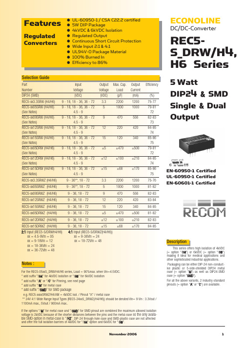
Notes :
For the REC5-05xxS_DRW/H4/H6 series, Load = 90%max. when Vin=4.5VDC. * add suffix "/H4" for 4kVDC isolation or "/H6" for 6kVDC isolation * add suffix "/A" or "/C" for Pinning, see next page * add suffix "/M" for metal case
REC5-S_DRW/H4,H6 Series
2:1 & 4:1 ±2% max. ±0.3% max. ±0.6% max. 50mVp-p max. 120kHz typ. 200kHz typ. Pi Network see above 300mW max.
Load Regulation (for output load current change from 20% to 100%) Output Ripple and Noise (0,1µF capacitor on output, 20MHz BW) Operating Frequency at Full Load 2:1 input (at nominal input voltage) 4:1 input Input Filter Efficiency at Full Load No Load Power Consumption Isolation Voltage Rated Working Voltage Isolation Voltage Rated Working Voltage Isolation Capacitance Isolation Resistance Short Circuit Protection Operating Temperature (free air convection) Storage Temperature Range Relative Humidity Case Material Thermal Impedance Package Weight MTBF (+25°C) (+75°C) Natural convection using MIL-HDBK 217F using MIL-HDBK 217F H4 types (see note) H6 types (see note) (tested for 1 second) (long term isolation) (tested for 1 second) (long term isolation)
RP40-2412DGW中文资料
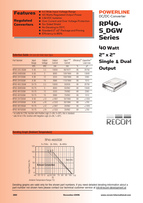
125 100 75 Output Power (%) 50 25
Natural Convection
0 -40 -25 -10 0 40 50 60 70 80 90 100 110 55 Ambient Temperature Range (°C)
RP40-243.3SGW RP40-2405SGW RP40-2412SGW RP40-2415SGW RP40-483.3SGW RP40-4805SGW RP40-4812SGW RP40-4815SGW RP40-2412DGW RP40-2415DGW RP40-4812DGW RP40-4815DGW
元器件交易网
Features
Regulated Converters
● ● ● ● ● ● ● ●
4:1 Wide Input Voltage Range 40 Watts Regulated Output Power 1.6kVDC Isolation Over Current and Over Voltage Protection Six-Sided Shield No Derating to 55°C Standard 2” x2” Package and Pinning Efficiency to 86%
* no suffix for CTRL function with Positive Logic (1=ON, 0=OFF), this is standard * add /N for CTRL function with Negative Logic (0=ON, 1=OFF)
FN2410 FN2412 标准性能单相过滤器说明书

DATA SHEETStandard Performance Single-Phase Filters FN2410 and FN2412EMC/RFI Filters for Industrial ElectronicsExcellent filter performance for applications with high interference levelsFilters for two-phase supply up to 2x 520 VAC (P-P) availableFast and comfortable snap-in installation on popular TS 35 DIN-rails up to 45 A Industrial grade terminal blocks for unsurpassed electrical safetyPerformance indicatorsTechnical SpecificationsMaximum continuous operating voltage 2x 520/300 VAC (FN 2410 H/FN 2412 H)1x 250 VAC (FN 2410/FN 2412)Operating frequencyDC to 400 HzRated currents8 to 45 A @ 50°C (FN 2412)8 to 100 A @ 50°C (FN 2410)High potential test voltageP –> P 2250 VDC for 2 sec (H types)P –> E 2000 VAC for 2 sec P –> N 1100 VDC for 2 secP –> E 2700 VDC for 2 sec (H types)Protection category IP 20Overload capability4x rated current at switch on,1.5x rated current for 1 minute, once per hour Temperature range (operation and storage)-25°C to +100°C (25/100/21)Flammability corresponding to UL 94 V-2 or betterDesign corresponding toUL 1283, CSA 22.2 No. 8 1986, IEC/EN 60939MTBF @ 50°C/250 V (Mil-HB-217F)1,200,000 hours250,000 hours (H types)Approvals & CompliancesFeatures and BenefitsTypical ApplicationsFN 2410 filters up to 100 A are designed for traditional chassis mountingFor extra fast installation, FN 2412 filters up to 45 A can comfortably be snapped-in on popular TS 35DIN-rails which are common in most electrical cabinetsBoth FN 2410 and FN 2412 are also avail- able as …H versions“. These are ideally suitable for anoperation on two phases in a three-phase power network, handling voltages up to 520 VAC All filters provide an exceptional conductedattenuation performance, based on chokes with high saturation resistance and excellent thermal behavior. Thus, all filters retain the expected filter performance even in very noisy applications and under full load conditionsTouch-safe industrial grade terminal blocks provide maximum electrical safety and protect humans from undeliberate contact with life conductors. They help to fulfill the mostdemanding installation standardsSmall to medium-sized machines and industrial equipmentHigh-end single-phase power supplies Single-phase variable speed motor drives,inverters and convertersDIN-rail filter versions are ideal for panel building and electrical cabinetsVarious noisy applications with higher power single-phase or two-phase supply Typical electrical schematicFilterRated current Leakage current*Power loss Input/Output Weight@ 50°C (40°C)@ 250 VAC /50 Hz @ 25°C/50 Hzconnections(@ 120 VAC /60 Hz)[A][mA][W][kg]FN 2410-8-448 (8.8) 2.60 (1.49) 2.6-440.4FN 2410-16-4416 (17.5) 2.60 (1.49) 3.5-440.5FN 2410-25-3325 (27.4) 2.60 (1.49) 5.5-330.6FN 2410-32-3332 (35.0) 2.60 (1.49) 5.6-330.7FN 2410-45-3345 (49.3) 2.60 (1.49)7.4-330.7FN 2410-60-3460 (65.7) 2.60 (1.49) 5.5-34 1.8FN 2410-80-3480 (87.6) 2.60 (1.49)9.9-34 1.8FN 2410-100-34100 (109.5)2.60 (1.49)15.4-34 1.8FN 2410 H-8-448 (8.8) 2.60 (1.49) 2.6-440.5FN 2410 H-16-4416 (17.5) 2.60 (1.49)3.5-440.6FN 2410 H-25-3325 (27.4) 2.60 (1.49) 5.5-330.7FN 2410 H-32-3332 (35.0) 2.60 (1.49) 5.6-330.8FN 2410 H-60-3460 (65.7) 2.60 (1.49) 5.5-34 1.9FN 2410 H-80-3480 (87.6) 2.60 (1.49)9.9-34 1.9FN 2410 H-100-34100 (109.5)2.60 (1.49)15.4-34 1.9FN 2412-8-448 (8.8) 2.60 (1.49) 2.6-440.4FN 2412-16-4416 (17.5) 2.60 (1.49)3.5-440.6FN 2412-25-3325 (27.4) 2.60 (1.49) 5.5-330.7FN 2412-32-3332 (35.0) 2.60 (1.49) 5.6-330.8FN 2412-45-3345 (49.3) 2.60 (1.49)7.4-330.8FN 2412 H-8-448 (8.8) 2.60 (1.49) 2.6-440.5FN 2412 H-16-4416 (17.5) 2.60 (1.49) 3.5-440.7FN 2412 H-25-3325 (27.4) 2.60 (1.49) 5.5-330.8FN 2412 H-32-3332 (35.0)2.60 (1.49)5.6-330.9* Maximum leakage under normal operating conditions (acc. to IEC60939-3). Note: if the neutral line is interrupted, worst case leakage could reach twice this level.Filter Selection TablePer CISPR 17; A=50 Ω/50 Ω sym; B=50 Ω/50 Ω asym; C=0.1 Ω/100 Ω sym; D=100 Ω/0.1 Ω sym Typical Filter Attenuation8 to 45 A types60 to 100 A typesMechanical DataFN 2410 (H)FN 2412 (H)FN 2410FN 24128 A16 A 25 A 32 A 45 A 60 A 80 A 100 A 8 A 16 A 25 A 32 A 45 A A 130130130130130165165165110110110110110B 93939393931151151159393939393C 62627676761001001007373878787D 108108108108108140140140E 120120120120120155155155F 7070707070909090G 5.3 5.3 5.3 5.3 5.3 5.3 5.3 5.3H 1.0 1.0 1.0 1.0 1.0 1.2 1.2 1.2I 22222525253939392222252525JM6M6M6M6M6M8M8M8M6M6M6M6M6Rec. torque (Nm) 3.5 - 4.0 3.5 - 4.0 3.5 - 4.0 3.5 - 4.0 3.5 - 4.08.0 - 9.08.0 - 9.08.0 - 9.0 3.5 - 4.0 3.5 - 4.0 3.5 - 4.0 3.5 - 4.0 3.5 - 4.0L17.517.531.531.531.539.239.239.228.528.542.542.542.5All dimensions in mm; 1 inch = 25.4 mmTolerances according: ISO 2768-m/EN 22768-mDimensions-33-34-44Solid wire 16 mm 235 mm 210 mm 2Flex wire 10 mm 225 mm 2 6 mm 2AWG type wire AWG 6AWG 2AWG 8Recommended torque1.5-1.8 Nm4.0-4.5 Nm1.0-1.2 NmPlease visit to find more details on filter connectors.Filter Input/Output Connector Cross SectionsTo find your local partner within Schaffner‘s global network © 2022 Schaffner GroupThe content of this document has been carefully checked and understood.However,neither Schaffner nor its subsidiaries assume any liability whatsoever for any errors or inaccuracies of this document and the consequences thereof.Published specifica-tions are subject to change without notice.Product suitability for any area of application must ultimately be determined by the customer.In all cases,products must never be operated outside their published specifications.Schaffner does not guarantee the availability of all published products.This disclaimer shall be governed by substantive Swiss law and resulting disputes shall be settled by the courts at the place of business of Schaffner Holding test publications and a complete disclaimer can be downloa-ded from the Schaffner website.All trademarks recognized.Headquarters, Global Innovation and DevelopmentSwitzerlandSchaffner Holding AG Industrie Nord Nordstrasse 11e 4542Luterbach+41 32 681 66 26******************Sales and Application CentersChinaSchaffner EMC Ltd. ShanghaiT20-3 C, No 565 Chuangye Road,Pudong district 201201Shanghai+86 2138139500*********************FinlandSchaffner Oy Sauvonrinne 19 H 8500Lohja+358 50 468 7284**************************FranceSchaffner EMC S.A.S.16-20 Rue Louis Rameau 95875Bezons+33 1 34 34 30 60*************************GermanySchaffner Deutschland GmbH Schoemperlenstrasse 12B 76185Karlsruhe +49 721 56910**************************IndiaSchaffner India Pvt. Ltd Regus World Trade CentreWTC, 22nd Floor Unit No 2238, Brigade Gateway Campus, 26/1, Dr. Rajkumar Road Malleshwaram (W)560055Bangalore+91 8067935355************************ItalySchaffner EMC S.r.l.Via Ticino, 3020900Monza (MB)+39 039 21 41 070************************JapanSchaffner EMC K.K.ISM Sangenjaya 7F1-32-12 Kamiuma, Setagaya-ku 154-0011Tokyo+81 3 5712 3650************************SingaporeSchaffner EMC Pte Ltd.Blk 3015A Ubi Road 1, #05-09, Kampong Ubi Industrial Estate 408705Singapore +65 63773283****************************SpainSchaffner EMC EspañaCalle Caléndula 93, Miniparc III, Edificio E El Soto de Moraleja, Alcobendas 28109Madrid+34 917 912 900************************SwedenSchaffner EMC AB Östermalmstrorg 1114 42Stockholm+46 8 5050 2425*************************SwitzerlandSchaffner EMV AG Industrie Nord Nordstrasse 11e 4542Luterbach+41 32 681 66 26******************************TaiwanSchaffner EMV Ltd.U-Town20 Floor-2, No 97, Section 1, XinTai 5th Road,XiZhi District 22175New Taipei City +886 226975500*************************ThailandSchaffner EMC Co. Ltd.Sathorn Square TowerRoom 3780, 37FL, 98 North-Sathorn Rd,Silom, Bangrak 10500Bangkok+66 621056397***************************United Kingdom Schaffner Ltd.1, Oakmede Place Terrace Road RG42 4JF Binfield+44 118 9770070*********************United StatesSchaffner EMC Inc.52 Mayfield Avenue Edison, New Jersey +1 732 225 9533**********************。
TPS2412PW中文资料
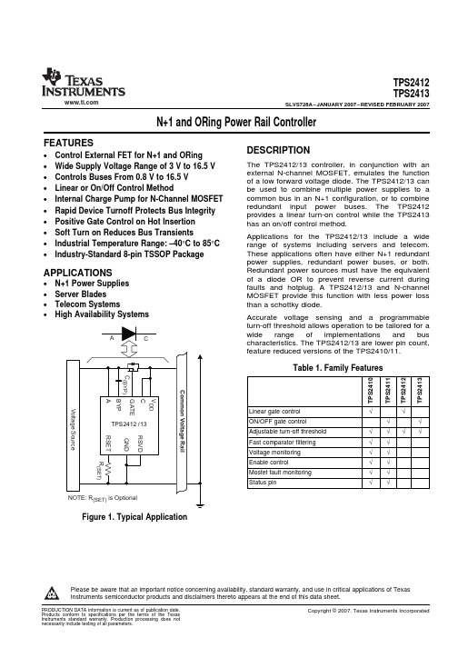
DEVICE TPS2412 TPS2413
ORDERING INFORMATION(1)
TEMPERATURE
PACKAGE (2)
ORDERING CODE
–40°C to 85°C
PW (TSSOP - 8)
TPS2412PW TPS2413PW
MARKING TPS2412 TPS2413
(1) Add an R suffix to the device type for tape and reel. (2) For the most current package and ordering information, see the Package Option Addendum at the end
Accurate voltage sensing and a programmable turn-off threshold allows operation to be tailored for a wide range of implementations and bus characteristics. The TPS2412/13 are lower pin count, feature reduced versions of the TPS2410/11.
VALUE –0.3 to 18
7.5 18 –0.3 to 30 –0.3 to 13 0.3 –0.3 to 7 Indefinite 2 500 Internally liited –65 to 150
UNIT V V V V V V V
kV V °C °C
(1) Stresses beyond those listed under absolute maximum ratings may cause permanent damage to the device. These are stress ratings only and functional operation of the device at these or any other conditions beyond those indicated under recommended operating conditions is not implied. Exposure to absolute-maximum-rated conditions for extended periods may affect device reliability.
LM124DRG4资料
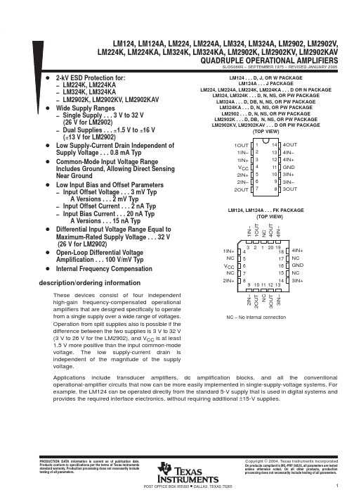
PACKAGING INFORMATIONOrderableDevice Status (1)Package Type Package DrawingPins Package Qty Eco Plan (2)Lead/Ball Finish MSL Peak Temp (3)5962-7704301VCAACTIVE CDIP J 141TBD A42SNPB N /A for Pkg Type 77043012A ACTIVE LCCC FK 201TBD POST-PLATE N /A for Pkg Type7704301CA ACTIVE CDIP J 141TBD A42SNPB N /A for Pkg Type 7704301DA ACTIVE CFP W 141TBD A42SNPB N /A for Pkg Type 77043022A ACTIVE LCCC FK 201TBD POST-PLATE N /A for Pkg Type7704302CA ACTIVE CDIP J 141TBD A42SNPB N /A for Pkg Type JM38510/11005BCAACTIVE CDIP J 141TBD A42SNPB N /A for Pkg Type LM124ADR OBSOLETE SOIC D 14TBD Call TI Call TILM124AFKB ACTIVE LCCC FK 201TBD POST-PLATE N /A for Pkg TypeLM124AJ ACTIVE CDIP J 141TBD A42SNPB N /A for Pkg Type LM124AJB ACTIVE CDIP J 141TBD A42SNPB N /A for Pkg Type LM124D ACTIVE SOIC D 1450TBD CU NIPDAU Level-3-245C-168HR LM124DG4ACTIVE SOIC D 1450Green (RoHS &no Sb/Br)CU NIPDAU Level-1-260C-UNLIM LM124DR ACTIVE SOIC D 142500TBDCU NIPDAU Level-3-245C-168HR LM124DRG4ACTIVE SOIC D 142500Green (RoHS &no Sb/Br)CU NIPDAULevel-1-260C-UNLIMLM124FKB ACTIVE LCCC FK 201TBD POST-PLATE N /A for Pkg Type LM124J ACTIVE CDIP J 141TBD A42SNPB N /A for Pkg Type LM124JB ACTIVE CDIP J 141TBD A42SNPB N /A for Pkg Type LM124N OBSOLETE PDIP N 14TBD Call TI Call TILM124W ACTIVE CFP W 141TBD A42SNPB N /A for Pkg Type LM124WB ACTIVE CFP W 141TBD A42SNPB N /A for Pkg Type LM224AD ACTIVE SOIC D 1450Green (RoHS &no Sb/Br)CU NIPDAU Level-1-260C-UNLIM LM224ADE4ACTIVE SOIC D 1450Green (RoHS &no Sb/Br)CU NIPDAU Level-1-260C-UNLIM LM224ADG4ACTIVE SOIC D 1450Green (RoHS &no Sb/Br)CU NIPDAU Level-1-260C-UNLIM LM224ADR ACTIVE SOIC D 142500Green (RoHS &no Sb/Br)CU NIPDAU Level-1-260C-UNLIM LM224ADRE4ACTIVE SOIC D 142500Green (RoHS &no Sb/Br)CU NIPDAU Level-1-260C-UNLIM LM224ADRG4ACTIVE SOIC D 142500Green (RoHS &no Sb/Br)CU NIPDAU Level-1-260C-UNLIM LM224AN ACTIVE PDIP N 1425Pb-Free (RoHS)CU NIPDAU N /A for Pkg Type LM224ANE4ACTIVE PDIP N 1425Pb-Free (RoHS)CU NIPDAU N /A for Pkg Type LM224D ACTIVE SOIC D 1450Green (RoHS &no Sb/Br)CU NIPDAU Level-1-260C-UNLIM LM224DE4ACTIVE SOIC D 1450Green (RoHS &no Sb/Br)CU NIPDAU Level-1-260C-UNLIM LM224DG4ACTIVE SOIC D 1450Green (RoHS &no Sb/Br)CU NIPDAU Level-1-260C-UNLIM LM224DRACTIVESOICD142500Green (RoHS &CU NIPDAULevel-1-260C-UNLIMPACKAGE OPTION ADDENDUM9-Oct-2007Addendum-Page 1OrderableDeviceStatus (1)Package Type Package DrawingPins Package QtyEco Plan (2)Lead/Ball FinishMSL Peak Temp (3)no Sb/Br)LM224DRE4ACTIVE SOIC D 142500Green (RoHS &no Sb/Br)CU NIPDAU Level-1-260C-UNLIM LM224DRG4ACTIVE SOIC D 142500Green (RoHS &no Sb/Br)CU NIPDAU Level-1-260C-UNLIM LM224KAD ACTIVE SOIC D 1450Green (RoHS &no Sb/Br)CU NIPDAU Level-1-260C-UNLIM LM224KADE4ACTIVE SOIC D 1450Green (RoHS &no Sb/Br)CU NIPDAU Level-1-260C-UNLIM LM224KADG4ACTIVE SOIC D 1450Green (RoHS &no Sb/Br)CU NIPDAU Level-1-260C-UNLIM LM224KADR ACTIVE SOIC D 142500Green (RoHS &no Sb/Br)CU NIPDAU Level-1-260C-UNLIM LM224KADRE4ACTIVE SOIC D 142500Green (RoHS &no Sb/Br)CU NIPDAU Level-1-260C-UNLIM LM224KADRG4ACTIVE SOIC D 142500Green (RoHS &no Sb/Br)CU NIPDAU Level-1-260C-UNLIM LM224KAN ACTIVE PDIP N 1425Pb-Free (RoHS)CU NIPDAU N /A for Pkg Type LM224KANE4ACTIVE PDIP N 1425Pb-Free (RoHS)CU NIPDAU N /A for Pkg Type LM224KD ACTIVE SOIC D 1450Green (RoHS &no Sb/Br)CU NIPDAU Level-1-260C-UNLIM LM224KDE4ACTIVE SOIC D 1450Green (RoHS &no Sb/Br)CU NIPDAU Level-1-260C-UNLIM LM224KDG4ACTIVE SOIC D 1450Green (RoHS &no Sb/Br)CU NIPDAU Level-1-260C-UNLIM LM224KDR ACTIVE SOIC D 142500Green (RoHS &no Sb/Br)CU NIPDAU Level-1-260C-UNLIM LM224KDRE4ACTIVE SOIC D 142500Green (RoHS &no Sb/Br)CU NIPDAU Level-1-260C-UNLIM LM224KDRG4ACTIVE SOIC D 142500Green (RoHS &no Sb/Br)CU NIPDAU Level-1-260C-UNLIM LM224KN ACTIVE PDIP N 1425Pb-Free (RoHS)CU NIPDAU N /A for Pkg Type LM224KNE4ACTIVE PDIP N 1425Pb-Free (RoHS)CU NIPDAU N /A for Pkg Type LM224N ACTIVE PDIP N 1425Pb-Free (RoHS)CU NIPDAU N /A for Pkg Type LM224NE4ACTIVE PDIP N 1425Pb-Free (RoHS)CU NIPDAU N /A for Pkg Type LM2902D ACTIVE SOIC D 1450Green (RoHS &no Sb/Br)CU NIPDAU Level-1-260C-UNLIM LM2902DE4ACTIVE SOIC D 1450Green (RoHS &no Sb/Br)CU NIPDAU Level-1-260C-UNLIM LM2902DG4ACTIVE SOIC D 1450Green (RoHS &no Sb/Br)CU NIPDAU Level-1-260C-UNLIM LM2902DR ACTIVE SOIC D 142500Green (RoHS &no Sb/Br)CU NIPDAU Level-1-260C-UNLIM LM2902DRE4ACTIVESOICD142500Green (RoHS &no Sb/Br)CU NIPDAULevel-1-260C-UNLIM9-Oct-2007OrderableDevice Status (1)Package Type Package DrawingPins Package Qty Eco Plan (2)Lead/Ball Finish MSL Peak Temp (3)LM2902DRG4ACTIVE SOIC D 142500Green (RoHS &no Sb/Br)CU NIPDAU Level-1-260C-UNLIM LM2902KAVQDR NRND SOIC D 142500Pb-Free (RoHS)CU NIPDAU Level-2-250C-1YEAR/Level-1-235C-UNLIM LM2902KAVQDRG4ACTIVE SOIC D 142500Green (RoHS &no Sb/Br)CU NIPDAU Level-1-260C-UNLIM LM2902KAVQPWR ACTIVE TSSOP PW 142000TBDCU NIPDAU Level-1-250C-UNLIM LM2902KAVQPWRG4ACTIVE TSSOP PW 142000Green (RoHS &no Sb/Br)CU NIPDAU Level-1-260C-UNLIM LM2902KD ACTIVE SOIC D 1450Green (RoHS &no Sb/Br)CU NIPDAU Level-1-260C-UNLIM LM2902KDB ACTIVE SSOP DB 1480Green (RoHS &no Sb/Br)CU NIPDAU Level-1-260C-UNLIM LM2902KDBE4ACTIVE SSOP DB 1480Green (RoHS &no Sb/Br)CU NIPDAU Level-1-260C-UNLIM LM2902KDBG4ACTIVE SSOP DB 1480Green (RoHS &no Sb/Br)CU NIPDAU Level-1-260C-UNLIM LM2902KDBR ACTIVE SSOP DB 142000Green (RoHS &no Sb/Br)CU NIPDAU Level-1-260C-UNLIM LM2902KDBRE4ACTIVE SSOP DB 142000Green (RoHS &no Sb/Br)CU NIPDAU Level-1-260C-UNLIM LM2902KDBRG4ACTIVE SSOP DB 142000Green (RoHS &no Sb/Br)CU NIPDAU Level-1-260C-UNLIM LM2902KDE4ACTIVE SOIC D 1450Green (RoHS &no Sb/Br)CU NIPDAU Level-1-260C-UNLIM LM2902KDG4ACTIVE SOIC D 1450Green (RoHS &no Sb/Br)CU NIPDAU Level-1-260C-UNLIM LM2902KDR ACTIVE SOIC D 142500Green (RoHS &no Sb/Br)CU NIPDAU Level-1-260C-UNLIM LM2902KDRE4ACTIVE SOIC D 142500Green (RoHS &no Sb/Br)CU NIPDAU Level-1-260C-UNLIM LM2902KDRG4ACTIVE SOIC D 142500Green (RoHS &no Sb/Br)CU NIPDAU Level-1-260C-UNLIM LM2902KN ACTIVE PDIP N 1425Pb-Free (RoHS)CU NIPDAU N /A for Pkg Type LM2902KNE4ACTIVE PDIP N 1425Pb-Free (RoHS)CU NIPDAU N /A for Pkg Type LM2902KNSR ACTIVE SO NS 142000Green (RoHS &no Sb/Br)CU NIPDAU Level-1-260C-UNLIM LM2902KNSRE4ACTIVE SO NS 142000Green (RoHS &no Sb/Br)CU NIPDAU Level-1-260C-UNLIM LM2902KNSRG4ACTIVE SO NS 142000Green (RoHS &no Sb/Br)CU NIPDAU Level-1-260C-UNLIM LM2902KPW ACTIVE TSSOP PW 1490Green (RoHS &no Sb/Br)CU NIPDAU Level-1-260C-UNLIM LM2902KPWE4ACTIVE TSSOP PW 1490Green (RoHS &no Sb/Br)CU NIPDAU Level-1-260C-UNLIM LM2902KPWG4ACTIVE TSSOP PW 1490Green (RoHS &no Sb/Br)CU NIPDAU Level-1-260C-UNLIM LM2902KPWRACTIVETSSOPPW142000Green (RoHS &no Sb/Br)CU NIPDAULevel-1-260C-UNLIM9-Oct-2007OrderableDevice Status (1)Package Type Package Drawing Pins Package Qty Eco Plan (2)Lead/Ball Finish MSL Peak Temp (3)LM2902KPWRE4ACTIVE TSSOP PW 142000Green (RoHS &no Sb/Br)CU NIPDAU Level-1-260C-UNLIM LM2902KPWRG4ACTIVE TSSOP PW 142000Green (RoHS &no Sb/Br)CU NIPDAU Level-1-260C-UNLIM LM2902KVQDR NRND SOIC D 142500Pb-Free (RoHS)CU NIPDAU Level-2-250C-1YEAR/Level-1-235C-UNLIM LM2902KVQDRG4ACTIVE SOIC D 142500Green (RoHS &no Sb/Br)CU NIPDAU Level-1-260C-UNLIM LM2902KVQPWR ACTIVE TSSOP PW 142000TBDCU NIPDAU Level-1-250C-UNLIM LM2902KVQPWRG4ACTIVE TSSOP PW 142000Green (RoHS &no Sb/Br)CU NIPDAU Level-1-260C-UNLIM LM2902N ACTIVE PDIP N 1425Pb-Free (RoHS)CU NIPDAU N /A for Pkg Type LM2902NE4ACTIVE PDIP N 1425Pb-Free (RoHS)CU NIPDAU N /A for Pkg Type LM2902NSR ACTIVE SO NS 142000Green (RoHS &no Sb/Br)CU NIPDAU Level-1-260C-UNLIM LM2902NSRG4ACTIVE SO NS 142000Green (RoHS &no Sb/Br)CU NIPDAU Level-1-260C-UNLIM LM2902PW ACTIVE TSSOP PW 1490Green (RoHS &no Sb/Br)CU NIPDAU Level-1-260C-UNLIM LM2902PWE4ACTIVE TSSOP PW 1490Green (RoHS &no Sb/Br)CU NIPDAU Level-1-260C-UNLIM LM2902PWG4ACTIVE TSSOP PW 1490Green (RoHS &no Sb/Br)CU NIPDAU Level-1-260C-UNLIM LM2902PWLE OBSOLETE TSSOP PW 14TBDCall TI Call TILM2902PWR ACTIVE TSSOP PW 142000Green (RoHS &no Sb/Br)CU NIPDAU Level-1-260C-UNLIM LM2902PWRE4ACTIVE TSSOP PW 142000Green (RoHS &no Sb/Br)CU NIPDAU Level-1-260C-UNLIM LM2902PWRG4ACTIVE TSSOP PW 142000Green (RoHS &no Sb/Br)CU NIPDAU Level-1-260C-UNLIM LM2902QN OBSOLETE PDIP N 14TBD Call TI Call TILM324AD ACTIVE SOIC D 1450Green (RoHS &no Sb/Br)CU NIPDAU Level-1-260C-UNLIM LM324ADBLE OBSOLETE SSOP DB 14TBDCall TI Call TILM324ADBR ACTIVE SSOP DB 142000Green (RoHS &no Sb/Br)CU NIPDAU Level-1-260C-UNLIM LM324ADBRE4ACTIVE SSOP DB 142000Green (RoHS &no Sb/Br)CU NIPDAU Level-1-260C-UNLIM LM324ADBRG4ACTIVE SSOP DB 142000Green (RoHS &no Sb/Br)CU NIPDAU Level-1-260C-UNLIM LM324ADE4ACTIVE SOIC D 1450Green (RoHS &no Sb/Br)CU NIPDAU Level-1-260C-UNLIM LM324ADG4ACTIVE SOIC D 1450Green (RoHS &no Sb/Br)CU NIPDAU Level-1-260C-UNLIM LM324ADR ACTIVE SOIC D 142500Green (RoHS &no Sb/Br)CU NIPDAU Level-1-260C-UNLIM LM324ADRE4ACTIVE SOIC D 142500Green (RoHS &no Sb/Br)CU NIPDAU Level-1-260C-UNLIM LM324ADRG4ACTIVESOICD142500Green (RoHS &CU NIPDAULevel-1-260C-UNLIM9-Oct-2007Orderable Device Status(1)PackageType PackageDrawingPins PackageQtyEco Plan(2)Lead/Ball Finish MSL Peak Temp(3)no Sb/Br)LM324AN ACTIVE PDIP N1425Pb-Free(RoHS)CU NIPDAU N/A for Pkg TypeLM324ANE4ACTIVE PDIP N1425Pb-Free(RoHS)CU NIPDAU N/A for Pkg TypeLM324ANSR ACTIVE SO NS142000Green(RoHS&no Sb/Br)CU NIPDAU Level-1-260C-UNLIMLM324ANSRE4ACTIVE SO NS142000Green(RoHS&no Sb/Br)CU NIPDAU Level-1-260C-UNLIMLM324ANSRG4ACTIVE SO NS142000Green(RoHS&no Sb/Br)CU NIPDAU Level-1-260C-UNLIMLM324APW ACTIVE TSSOP PW1490Green(RoHS&no Sb/Br)CU NIPDAU Level-1-260C-UNLIMLM324APWE4ACTIVE TSSOP PW1490Green(RoHS&no Sb/Br)CU NIPDAU Level-1-260C-UNLIMLM324APWG4ACTIVE TSSOP PW1490Green(RoHS&no Sb/Br)CU NIPDAU Level-1-260C-UNLIM LM324APWLE OBSOLETE TSSOP PW14TBD Call TI Call TILM324APWR ACTIVE TSSOP PW142000Green(RoHS&no Sb/Br)CU NIPDAU Level-1-260C-UNLIMLM324APWRE4ACTIVE TSSOP PW142000Green(RoHS&no Sb/Br)CU NIPDAU Level-1-260C-UNLIMLM324APWRG4ACTIVE TSSOP PW142000Green(RoHS&no Sb/Br)CU NIPDAU Level-1-260C-UNLIMLM324D ACTIVE SOIC D1450Green(RoHS&no Sb/Br)CU NIPDAU Level-1-260C-UNLIMLM324DE4ACTIVE SOIC D1450Green(RoHS&no Sb/Br)CU NIPDAU Level-1-260C-UNLIMLM324DG4ACTIVE SOIC D1450Green(RoHS&no Sb/Br)CU NIPDAU Level-1-260C-UNLIMLM324DR ACTIVE SOIC D142500Green(RoHS&no Sb/Br)CU NIPDAU Level-1-260C-UNLIMLM324DRE4ACTIVE SOIC D142500Green(RoHS&no Sb/Br)CU NIPDAU Level-1-260C-UNLIMLM324DRG4ACTIVE SOIC D142500Green(RoHS&no Sb/Br)CU NIPDAU Level-1-260C-UNLIMLM324KAD ACTIVE SOIC D1450Green(RoHS&no Sb/Br)CU NIPDAU Level-1-260C-UNLIMLM324KADE4ACTIVE SOIC D1450Green(RoHS&no Sb/Br)CU NIPDAU Level-1-260C-UNLIMLM324KADG4ACTIVE SOIC D1450Green(RoHS&no Sb/Br)CU NIPDAU Level-1-260C-UNLIMLM324KADR ACTIVE SOIC D142500Green(RoHS&no Sb/Br)CU NIPDAU Level-1-260C-UNLIMLM324KADRE4ACTIVE SOIC D142500Green(RoHS&no Sb/Br)CU NIPDAU Level-1-260C-UNLIMLM324KADRG4ACTIVE SOIC D142500Green(RoHS&no Sb/Br)CU NIPDAU Level-1-260C-UNLIMLM324KAN ACTIVE PDIP N1425Pb-Free(RoHS)CU NIPDAU N/A for Pkg TypeLM324KANE4ACTIVE PDIP N1425Pb-Free CU NIPDAU N/A for Pkg Type 9-Oct-2007OrderableDeviceStatus (1)Package Type Package Drawing Pins Package QtyEco Plan (2)Lead/Ball FinishMSL Peak Temp (3)(RoHS)LM324KANS PREVIEW SO NS 1450Green (RoHS &no Sb/Br)CU NIPDAU Level-1-260C-UNLIM LM324KANSR ACTIVE SO NS 142000Green (RoHS &no Sb/Br)CU NIPDAU Level-1-260C-UNLIM LM324KANSRE4ACTIVE SO NS 142000Green (RoHS &no Sb/Br)CU NIPDAU Level-1-260C-UNLIM LM324KANSRG4ACTIVE SO NS 142000Green (RoHS &no Sb/Br)CU NIPDAU Level-1-260C-UNLIM LM324KAPW ACTIVE TSSOP PW 1490Green (RoHS &no Sb/Br)CU NIPDAU Level-1-260C-UNLIM LM324KAPWE4ACTIVE TSSOP PW 1490Green (RoHS &no Sb/Br)CU NIPDAU Level-1-260C-UNLIM LM324KAPWG4ACTIVE TSSOP PW 1490Green (RoHS &no Sb/Br)CU NIPDAU Level-1-260C-UNLIM LM324KAPWR ACTIVE TSSOP PW 142000Green (RoHS &no Sb/Br)CU NIPDAU Level-1-260C-UNLIM LM324KAPWRE4ACTIVE TSSOP PW 142000Green (RoHS &no Sb/Br)CU NIPDAU Level-1-260C-UNLIM LM324KAPWRG4ACTIVE TSSOP PW 142000Green (RoHS &no Sb/Br)CU NIPDAU Level-1-260C-UNLIM LM324KD ACTIVE SOIC D 1450Green (RoHS &no Sb/Br)CU NIPDAU Level-1-260C-UNLIM LM324KDE4ACTIVE SOIC D 1450Green (RoHS &no Sb/Br)CU NIPDAU Level-1-260C-UNLIM LM324KDG4ACTIVE SOIC D 1450Green (RoHS &no Sb/Br)CU NIPDAU Level-1-260C-UNLIM LM324KDR ACTIVE SOIC D 142500Green (RoHS &no Sb/Br)CU NIPDAU Level-1-260C-UNLIM LM324KDRE4ACTIVE SOIC D 142500Green (RoHS &no Sb/Br)CU NIPDAU Level-1-260C-UNLIM LM324KDRG4ACTIVE SOIC D 142500Green (RoHS &no Sb/Br)CU NIPDAU Level-1-260C-UNLIM LM324KN ACTIVE PDIP N 1425Pb-Free (RoHS)CU NIPDAU N /A for Pkg Type LM324KNE4ACTIVE PDIP N 1425Pb-Free (RoHS)CU NIPDAU N /A for Pkg Type LM324KNS PREVIEW SO NS 1450Green (RoHS &no Sb/Br)CU NIPDAU Level-1-260C-UNLIM LM324KNSR ACTIVE SO NS 142000Green (RoHS &no Sb/Br)CU NIPDAU Level-1-260C-UNLIM LM324KNSRE4ACTIVE SO NS 142000Green (RoHS &no Sb/Br)CU NIPDAU Level-1-260C-UNLIM LM324KNSRG4ACTIVE SO NS 142000Green (RoHS &no Sb/Br)CU NIPDAU Level-1-260C-UNLIM LM324KPW ACTIVE TSSOP PW 1490Green (RoHS &no Sb/Br)CU NIPDAU Level-1-260C-UNLIM LM324KPWE4ACTIVE TSSOP PW 1490Green (RoHS &no Sb/Br)CU NIPDAU Level-1-260C-UNLIM LM324KPWG4ACTIVETSSOPPW1490Green (RoHS &no Sb/Br)CU NIPDAULevel-1-260C-UNLIM9-Oct-2007Orderable Device Status(1)PackageType PackageDrawingPins PackageQtyEco Plan(2)Lead/Ball Finish MSL Peak Temp(3)LM324KPWR ACTIVE TSSOP PW142000Green(RoHS&no Sb/Br)CU NIPDAU Level-1-260C-UNLIMLM324KPWRE4ACTIVE TSSOP PW142000Green(RoHS&no Sb/Br)CU NIPDAU Level-1-260C-UNLIMLM324KPWRG4ACTIVE TSSOP PW142000Green(RoHS&no Sb/Br)CU NIPDAU Level-1-260C-UNLIMLM324N ACTIVE PDIP N1425Pb-Free(RoHS)CU NIPDAU N/A for Pkg TypeLM324NE4ACTIVE PDIP N1425Pb-Free(RoHS)CU NIPDAU N/A for Pkg TypeLM324NSR ACTIVE SO NS142000Green(RoHS&no Sb/Br)CU NIPDAU Level-1-260C-UNLIMLM324NSRE4ACTIVE SO NS142000Green(RoHS&no Sb/Br)CU NIPDAU Level-1-260C-UNLIMLM324NSRG4ACTIVE SO NS142000Green(RoHS&no Sb/Br)CU NIPDAU Level-1-260C-UNLIMLM324PW ACTIVE TSSOP PW1490Green(RoHS&no Sb/Br)CU NIPDAU Level-1-260C-UNLIMLM324PWE4ACTIVE TSSOP PW1490Green(RoHS&no Sb/Br)CU NIPDAU Level-1-260C-UNLIMLM324PWG4ACTIVE TSSOP PW1490Green(RoHS&no Sb/Br)CU NIPDAULevel-1-260C-UNLIMLM324PWLE OBSOLETE TSSOP PW14TBD Call TI Call TILM324PWR ACTIVE TSSOP PW142000Green(RoHS&no Sb/Br)CU NIPDAU Level-1-260C-UNLIMLM324PWRE4ACTIVE TSSOP PW142000Green(RoHS&no Sb/Br)CU NIPDAU Level-1-260C-UNLIMLM324PWRG4ACTIVE TSSOP PW142000Green(RoHS&no Sb/Br)CU NIPDAU Level-1-260C-UNLIM LM324Y OBSOLETE DIESALE Y0TBD Call TI Call TI(1)The marketing status values are defined as follows:ACTIVE:Product device recommended for new designs.LIFEBUY:TI has announced that the device will be discontinued,and a lifetime-buy period is in effect.NRND:Not recommended for new designs.Device is in production to support existing customers,but TI does not recommend using this part in a new design.PREVIEW:Device has been announced but is not in production.Samples may or may not be available.OBSOLETE:TI has discontinued the production of the device.(2)Eco Plan-The planned eco-friendly classification:Pb-Free(RoHS),Pb-Free(RoHS Exempt),or Green(RoHS&no Sb/Br)-please check /productcontent for the latest availability information and additional product content details.TBD:The Pb-Free/Green conversion plan has not been defined.Pb-Free(RoHS):TI's terms"Lead-Free"or"Pb-Free"mean semiconductor products that are compatible with the current RoHS requirements for all6substances,including the requirement that lead not exceed0.1%by weight in homogeneous materials.Where designed to be soldered at high temperatures,TI Pb-Free products are suitable for use in specified lead-free processes.Pb-Free(RoHS Exempt):This component has a RoHS exemption for either1)lead-based flip-chip solder bumps used between the die and package,or2)lead-based die adhesive used between the die and leadframe.The component is otherwise considered Pb-Free(RoHS compatible)as defined above.Green(RoHS&no Sb/Br):TI defines"Green"to mean Pb-Free(RoHS compatible),and free of Bromine(Br)and Antimony(Sb)based flame retardants(Br or Sb do not exceed0.1%by weight in homogeneous material)(3)MSL,Peak Temp.--The Moisture Sensitivity Level rating according to the JEDEC industry standard classifications,and peak solder temperature.9-Oct-2007Important Information and Disclaimer:The information provided on this page represents TI's knowledge and belief as of the date that it is provided.TI bases its knowledge and belief on information provided by third parties,and makes no representation or warranty as to the accuracy of such information.Efforts are underway to better integrate information from third parties.TI has taken and continues to take reasonable steps to provide representative and accurate information but may not have conducted destructive testing or chemical analysis on incoming materials and chemicals.TI and TI suppliers consider certain information to be proprietary,and thus CAS numbers and other limited information may not be available for release.In no event shall TI's liability arising out of such information exceed the total purchase price of the TI part(s)at issue in this document sold by TI to Customer on an annualbasis.9-Oct-2007TAPE AND REEL BOXINFORMATIONDevicePackage Pins SiteReel Diameter (mm)Reel Width (mm)A0(mm)B0(mm)K0(mm)P1(mm)W (mm)Pin1Quadrant LM224ADR D 14SITE 4133016 6.59.0 2.1816Q1LM224DR D 14SITE 4133016 6.59.0 2.1816Q1LM224KADR D 14SITE 4133016 6.59.0 2.1816Q1LM224KDR D 14SITE 4133016 6.59.0 2.1816Q1LM2902DR D 14SITE 2733016 6.59.0 2.1816Q1LM2902DR D 14SITE 4133016 6.59.0 2.1816Q1LM2902KDBR DB 14SITE 41330168.2 6.6 2.51216Q1LM2902KDR D 14SITE 4133016 6.59.0 2.1816Q1LM2902KNSR NS 14SITE 41330168.210.5 2.51216Q1LM2902KPWR PW 14SITE 41330127.0 5.6 1.6812Q1LM2902NSR NS 14SITE 41330168.210.5 2.51216Q1LM2902PWR PW 14SITE 41330127.0 5.6 1.6812Q1LM324ADBR DB 14SITE 41330168.2 6.6 2.51216Q1LM324ADR D 14SITE 4133016 6.59.0 2.1816Q1LM324ANSR NS 14SITE 41330168.210.5 2.51216Q1LM324APWR PW 14SITE 41330127.0 5.6 1.6812Q1LM324DR D 14SITE 2733016 6.59.0 2.1816Q1LM324DR D 14SITE 4133016 6.59.0 2.1816Q1LM324KADRD14SITE 41330166.59.02.1816Q14-Oct-2007DevicePackage Pins SiteReel Diameter (mm)Reel Width (mm)A0(mm)B0(mm)K0(mm)P1(mm)W (mm)Pin1Quadrant LM324KANSR NS 14SITE 41330168.210.5 2.51216Q1LM324KAPWR PW 14SITE 41330127.0 5.6 1.6812Q1LM324KDR D 14SITE 4133016 6.59.0 2.1816Q1LM324KNSR NS 14SITE 41330168.210.5 2.51216Q1LM324KPWR PW 14SITE 41330127.0 5.6 1.6812Q1LM324NSR NS 14SITE 41330168.210.52.51216Q1LM324PWRPW14SITE 41330127.05.61.6812Q1Device PackagePins Site Length (mm)Width (mm)Height (mm)LM224ADR D 14SITE 41346.0346.033.0LM224DR D 14SITE 41346.0346.033.0LM224KADR D 14SITE 41346.0346.033.0LM224KDR D 14SITE 41346.0346.033.0LM2902DR D 14SITE 27342.9336.628.58LM2902DR D 14SITE 41346.0346.033.0LM2902KDBR DB 14SITE 41346.0346.033.0LM2902KDR D 14SITE 41346.0346.033.0LM2902KNSR NS 14SITE 41346.0346.033.0LM2902KPWRPW14SITE 41346.0346.029.04-Oct-2007DevicePackage Pins Site Length (mm)Width (mm)Height (mm)LM2902NSR NS 14SITE 41346.0346.033.0LM2902PWR PW 14SITE 41346.0346.029.0LM324ADBR DB 14SITE 41346.0346.033.0LM324ADR D 14SITE 41346.0346.033.0LM324ANSR NS 14SITE 41346.0346.033.0LM324APWR PW 14SITE 41346.0346.029.0LM324DR D 14SITE 27342.9336.628.58LM324DR D 14SITE 41346.0346.033.0LM324KADR D 14SITE 41346.0346.033.0LM324KANSR NS 14SITE 41346.0346.033.0LM324KAPWR PW 14SITE 41346.0346.029.0LM324KDR D 14SITE 41346.0346.033.0LM324KNSR NS 14SITE 41346.0346.033.0LM324KPWR PW 14SITE 41346.0346.029.0LM324NSR NS 14SITE 41346.0346.033.0LM324PWRPW14SITE 41346.0346.029.04-Oct-2007IMPORTANT NOTICETexas Instruments Incorporated and its subsidiaries(TI)reserve the right to make corrections,modifications,enhancements, improvements,and other changes to its products and services at any time and to discontinue any product or service without notice. Customers should obtain the latest relevant information before placing orders and should verify that such information is current and complete.All products are sold subject to TI’s terms and conditions of sale supplied at the time of order acknowledgment.TI warrants performance of its hardware products to the specifications applicable at the time of sale in accordance with TI’s standard warranty.Testing and other quality control techniques are used to the extent TI deems necessary to support this warranty.Except where mandated by government requirements,testing of all parameters of each product is not necessarily performed.TI assumes no liability for applications assistance or customer product design.Customers are responsible for their products and applications using TI components.To minimize the risks associated with customer products and applications,customers should provide adequate design and operating safeguards.TI does not warrant or represent that any license,either express or implied,is granted under any TI patent right,copyright,mask work right,or other TI intellectual property right relating to any combination,machine,or process in which TI products or services are rmation published by TI regarding third-party products or services does not constitute a license from TI to use such products or services or a warranty or endorsement e of such information may require a license from a third party under the patents or other intellectual property of the third party,or a license from TI under the patents or other intellectual property of TI. Reproduction of TI information in TI data books or data sheets is permissible only if reproduction is without alteration and is accompanied by all associated warranties,conditions,limitations,and notices.Reproduction of this information with alteration is an unfair and deceptive business practice.TI is not responsible or liable for such altered rmation of third parties may be subject to additional restrictions.Resale of TI products or services with statements different from or beyond the parameters stated by TI for that product or service voids all express and any implied warranties for the associated TI product or service and is an unfair and deceptive business practice.TI is not responsible or liable for any such statements.TI products are not authorized for use in safety-critical applications(such as life support)where a failure of the TI product would reasonably be expected to cause severe personal injury or death,unless officers of the parties have executed an agreement specifically governing such use.Buyers represent that they have all necessary expertise in the safety and regulatory ramifications of their applications,and acknowledge and agree that they are solely responsible for all legal,regulatory and safety-related requirements concerning their products and any use of TI products in such safety-critical applications,notwithstanding any applications-related information or support that may be provided by TI.Further,Buyers must fully indemnify TI and its representatives against any damages arising out of the use of TI products in such safety-critical applications.TI products are neither designed nor intended for use in military/aerospace applications or environments unless the TI products are specifically designated by TI as military-grade or"enhanced plastic."Only products designated by TI as military-grade meet military specifications.Buyers acknowledge and agree that any such use of TI products which TI has not designated as military-grade is solely at the Buyer's risk,and that they are solely responsible for compliance with all legal and regulatory requirements in connection with such use.TI products are neither designed nor intended for use in automotive applications or environments unless the specific TI products are designated by TI as compliant with ISO/TS16949requirements.Buyers acknowledge and agree that,if they use anynon-designated products in automotive applications,TI will not be responsible for any failure to meet such requirements. Following are URLs where you can obtain information on other Texas Instruments products and application solutions:Products ApplicationsAmplifiers Audio /audioData Converters Automotive /automotiveDSP Broadband /broadbandInterface Digital Control /digitalcontrolLogic Military /militaryPower Mgmt Optical Networking /opticalnetworkMicrocontrollers Security /securityRFID Telephony /telephonyLow Power /lpw Video&Imaging /videoWirelessWireless /wirelessMailing Address:Texas Instruments,Post Office Box655303,Dallas,Texas75265Copyright©2007,Texas Instruments Incorporated。
REC3-2412DRWZH4中文资料
120 100 80 60 50 40 20 0 -40
Vin = 5V
300mW max. 4000VDC min. see Application Notes 6000VDC min. see Application Notes 20pF min. / 60pF max. 40pF min. / 80pF max. 1 GΩ min. Continuous, Auto Restart -40°C to +80°C (see Graph) -40°C to +85°C (see Graph)
Typical Characteristics
Single 2:1 Input Single 2:1 Input
Efficiency / Load
100 80 60 40
3 Watt DIP24 & SMD Single & Dual Output
EN-60950-1 Certified UL-60950-1 Certified EN-60601-1 Certified
Description
4:1 Input * add suffix /H4 for 4kVDC isolation or /H6 (REC3-S/DRWZ(H4/H6)) for 6kVDC isolation xx = 9-36Vin = 24 * add suffix "/A" or "/C" for Pinning, see next page xx = 18-72Vin = 48 “B” Pinning is NOT available for this series ! * add suffix "/M" for metal case * add suffix "/SMD" for SMD package e.g. REC3-2412SRW/H4/AM = 4kVDC isol. / Pinout "A" / metal case
ECONOLINE DC DC 转换器说明书
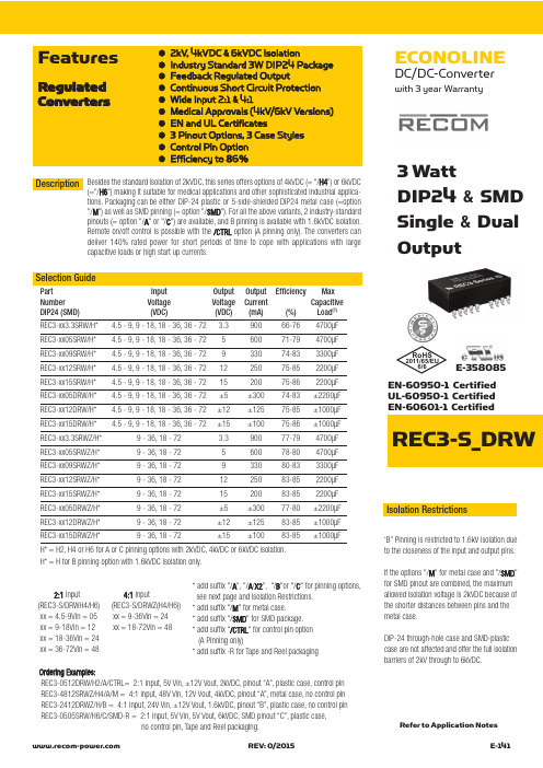
ECONOLINEDC/DC-Converterwith 3 year WarrantyREC3-S_DRW●2kV, 4kVDC &6kVDC Isolation●Industry Standard 3W DIP24 Package ●Feedback Regulated Output●Continuous Short Circuit Protection ●Wide Input 2:1 & 4:1●Medical Approvals (4kV/6kV Versions)●EN and UL Certificates●3 Pinout Options, 3 Case Styles ●Control Pin Option ●Efficiency to 86%FeaturesRegulated Converters3 WattDIP24 & SMD Single &DualOutputEN-60950-1 Certified UL-60950-1 Certified EN-60601-1 CertifiedSelection GuidePart Input Output Output Efficiency Max Number Voltage Voltage Current Capacitive DIP24 (SMD)(VDC)(VDC)(mA)(%)Load (1)REC3-xx3.3SRW/H* 4.5 - 9, 9 - 18, 18 - 36, 36 - 72 3.390066-764700µF REC3-xx05SRW/H* 4.5 - 9, 9 - 18, 18 - 36, 36 - 72560071-794700µF REC3-xx09SRW/H* 4.5 - 9, 9 - 18, 18 - 36, 36 - 72933074-833300µF REC3-xx12SRW/H* 4.5 - 9, 9 - 18, 18 - 36, 36 - 721225075-852200µF REC3-xx15SRW/H* 4.5 - 9, 9 - 18, 18 - 36, 36 - 721520075-862200µF REC3-xx05DRW/H* 4.5 - 9, 9 - 18, 18 - 36, 36 - 72±5±30074-83±2200µF REC3-xx12DRW/H* 4.5 - 9, 9 - 18, 18 - 36, 36 - 72±12±12575-85±1000µF REC3-xx15DRW/H* 4.5 - 9, 9 - 18, 18 - 36, 36 - 72±15±10075-86±1000µF REC3-xx3.3SRWZ/H*9 - 36, 18 - 72 3.390077-794700µF REC3-xx05SRWZ/H*9 - 36, 18 - 72560078-804700µF REC3-xx09SRWZ/H*9 - 36, 18 - 72933080-833300µF REC3-xx12SRWZ/H*9 - 36, 18 - 721225083-852200µF REC3-xx15SRWZ/H*9 - 36, 18 - 721520083-852200µF REC3-xx05DRWZ/H*9 - 36, 18 - 72±5±30077-80±2200µF REC3-xx12DRWZ/H*9 - 36, 18 - 72±12±12583-85±1000µF REC3-xx15DRWZ/H*9 - 36, 18 - 72±15±10083-85±1000µFH* = H2, H4 or H6 for A or C pinning options with 2kVDC, 4kVDC or 6kVDC isolation.H* = H for B pinning option with 1.6kVDC isolation only.Besides the standard isolation of 2kVDC, this series offers options of 4kVDC (= "/H4") or 6kVDC(="/H6") making it suitable for medical applications and other sophisticated industrial a pplica-tions. Packaging can be either DIP-24 plastic or 5-side-shielded DIP24 metal case (=option "/M ") as well as SMD pinning (= option "/SMD "). For all the above variants, 2 industry-standard pinouts (= option "/A "or "/C ") are available, and B pinning is available with 1.6kVDC isolation.Remote on/off control is possible with the /CTRL option (A pinning only). The converters can deliver 140% rated power for short periods of time to cope with applications with large capacitive loads or high start up currents.Description 2:1Input 4:1Input(REC3-S/DRWH4/H6) (REC3-S/DRWZ(H4/H6))xx = 4.5-9Vin = 05 xx = 9-36Vin = 24xx = 9-18Vin = 12 xx = 18-72Vin = 48 xx = 18-36Vin = 24xx = 36-72Vin = 48*add suffix "/A ", "/A /X2", "/B "or "/C " for pinning options,see next page and Isolation Restrictions.*add suffix "/M " for metal case.* add suffix "/SMD " for SMD package.* add suffix "/CTRL " for control pin option (A Pinning only)* add suffix -R for Tape and Reel packagingIsolation Restrictions‘B” Pinning is restricted to 1.6kV isolation dueto the closeness of the input and output pins.If the options "/M " for metal case and "/SMD "for SMD pinout are combined, the maximum allowed isolation voltage is 2kVDC because of the shorter distances between pins and the metal case.DIP-24 through-hole case and SMD-plastic case are not affected and offer the full isolation barriers of 2kV through to 6kVDC.Ordering Examples:REC3-0512DRW/H2/A/CTRL= 2:1 input, 5V Vin, ±12V Vout, 2kVDC, pinout “A”, plastic case, control pin REC3-4812SRWZ/H4/A/M = 4:1 input, 48V Vin, 12V Vout, 4kVDC, pinout “A”, metal case, no control pin REC3-2412DRWZ/H/B = 4:1 input, 24V Vin, ±12V Vout, 1.6kVDC, pinout “B”, plastic case, no control pin REC3-0505SRW/H6/C/SMD-R = 2:1 input, 5V Vin, 5V Vout, 6kVDC, SMD pinout “C”, plastic case,no control pin, Tape and Reel packaging.Refer to Application NotesE-358085RoHS2011/65/EU6/6Input Voltage Range 2:1 & 4:1Output Voltage Accuracy ±2% max.Line Regulation (HL-LL)±0.4% max.Load Regulation (for output load current change from 20% to 100%)±0.6% max.Minimum Load 10% (2)Output Ripple and Noise (0,1µF capacitor on output, 20MHz BW)50mVp-p max.Switching Frequency at Full Load 2:1 Input types 90kHz min. / 150kHz max.and nominal Input Voltage 4:1 Input types 120kHz min. / 180kHz max.Input Filter Pi Network Efficiency at Full Load see above No Load Power Consumption 300mW max.Isolation Voltage H2-Suffix (tested for 1 second)2000VDC(rated for 1 minute**)1000VAC / 60HzIsolation Voltage H4-Suffix (tested for 1 second)4000VDC(rated for 1 minute**)2000VAC / 60HzIsolation Voltage H6-Suffix (tested for 1 second)6000VDC(rated for 1 minute**)3000VAC / 60HzIsolation Capacitance 2:1 Input types 20pF min. / 60pF max.4:1 Input types 40pF min. / 80pF max.Isolation Resistance 1 G Ωmin.Short Circuit Protection (Max temp. = 60°C during short circuit conditions)Continuous, Auto Restart Operating Temperature Range 5V input types -40°C to +80°C (see Graph)(free air convection)others -40°C to +85°C (see Graph)Storage Temperature Range -55°C to +125°C Relative Humidity 95% RH Case Material Non-Conductive Plastic or Metal Thermal Impedance Natural convection 20°C/W for plastic case12°C/W for metal casePackage Weight 13g Packing Quantity 15 pcs per Tube100 pcs per ReelMTBF (+25°C)using MIL-HDBK 217F 1043 x 103 hours (+85°C)using MIL-HDBK 217F 186 x 103 hours Certifications UL General Safety Report: E358085UL 60950-1 1st Ed.C22.2 No. 60950-1-03EN General Safety Report: SPCLVD1212007EN60950-1:2006 + A1:2010+A12:2011EN Medical Safety Report: MDD1205098-3 + RM1205098-3 IEC/EN 60601-1 3rd Ed.Medical Report + ISO14971 Risk AssessmentDerating-Graph(Ambient T emperature)Specifications (measured at T A = 25°C, nominal input voltage, full load and after warm-up)O u t p u t P o w e r (%)1201002060125750-40Operating Temperature (°C)0805025804010010550Safe Operating AreaTypical CharacteristicsE f f i c i e n c y %100040%0%100%40Efficiency / Load 60%80%20%206080Total Output current (%)E f f i c i e n c y%100040%0%100%40Efficiency / Load 60%80%20%206080Total Output current (%)E f f i c i e n c y %10040%0%100%40Efficiency / Load60%80%20%206080Total Output current (%)Dual 2:1 InputSingle 2:1 InputSingle 2:1 Input Vin = 5VO u t p u t P o w e r (%)1201002060125750-40Operating Temperature (°C)0805025854010010550Safe Operating Area}Detailed Information seeApplication Notes chapter "MTBF"R E C 3-R WNotes Note 1:Maximum capacitive load is defined as the capacitive load that will allow start up in under 1 second without damage to the converter Note 2:The REC3-RW series requires a minimum of 10% load on the output to maintain specified regulation. Operating under no-load conditions will not damage these devices; however, they may not meet all listed specifications.**Any data referred to in this datasheet are of indicative nature and based on our practical experience only. For further details, please refer to our Application Notes.REC3-RW“C” Pinning /H2, /H4 & /H6E f f i c i e n c y %100040%0%100%40Efficiency / Load 60%80%20%206080Total Output current (%)E f f i c i e n c y %100040%0%100%40Efficiency / Load 60%80%20%206080Total Output current (%)E f f i c i e n c y %100040%0%100%40Efficiency / Load 60%80%20%206080Total Output current (%)Dual 4:1 InputSingle 4:1 InputSingle 4:1 Input Typical Characteristics - ContinuedPackage Style and Pinning (mm) DIP 24 , Wide Input 2:1 & 4:1“A” Pinning /H2, /H4 & /H6Pin Connections Pin #Single Single/X2Dual 1 (option)CTRL CTRL CTRL 2–Vin –Vin –Vin 3–Vin –Vin –Vin 9NC No Pin Com 11NC NC –Vout 14+Vout +Vout+Vout 16–Vout –Vout Com 22+Vin +Vin +Vin 23+Vin+Vin+VinNC = No Connection CTRL OptionVin+0V22,232,31CTRL TTL Input1k W RECx-xxxx/CTRL1N4148OnOffON = Open or 0V< V ctrl <1.2V OFF = 2.2V< V ctrl<12VCTRL OptionRecommended Footprint Details1Bottom View121110213152324Pin Connections Pin #Single Dual 1+Vin +Vin 2+Vin +Vin 10NC Com 11NC Com 12–Vout NC 13+Vout –Vout 15NC +Vout 23–Vin –Vin 24–Vin–VinNC = No ConnectionXX.X ± 0.5 mm XX.XX ± 0.25 mmRecommended Footprint DetailsXX.X ± 0.5 mm XX.XX ± 0.25 mm1Bottom View12111032131415222324Recommended Footprint DetailsXX.X ± 0.5 mm XX.XX ± 0.25 mmPackage Style and Pinning (mm) DIP 24 , Wide Input 2:1 & 4:1SMD PinningRecommended Footprint DetailsSMD pin connections follow standard package A (/A/SMD), B (/B/SMD) or C (/C/SMD) pinning.All unused pins are NC(No Connection). See Below for detailed pinout listsPin Connections Pin #Single Dual 1 (Option) CTRLCTRL 2–Vin –Vin 3–Vin –Vin 4NC NC 5NC NC 9NC Com 10NC NC 11NC -Vout 12NCNCPin Connections Pin #Single Dual 13 NC NC 14+Vout +Vout 15NC NC 16-Vout Com 20NC NC 21NC NC 22+Vin +Vin 23+Vin +Vin 24NCNCPin Connections Pin #Single Dual 1 +Vin +Vin 2NC –Vout 3NC Com 4NC NC 5NC NC 9NC NC 10-Vout Com 11+Vout +Vout 12-Vin-VinPin Connections Pin #Single Dual 13 -Vin -Vin 14+Vout +Vout 15-Vout Com 16NC NC 20NC NC 21NC NC 22NC Com 23NC -Vout 24+Vin+VinPin Connections Pin #Single Dual 1 +Vin +Vin 2+Vin +Vin 3NC NC 4NC NC 5NC NC 9NC NC 10NC Com 11NC Com 12-VoutNCPin Connections Pin #Single Dual 13 +Vout -Vout 14NC NC 15NC +Vout 16NC NC 20NC NC 21NC NC 22NC NC 23-Vin -Vin 24-Vin-Vin/A/SMD Pinning/B/SMD Pinning/C/SMD PinningPin Connections Pin #Single Dual 1+Vin +Vin 2No Pin –Vout 3No Pin Com 10–Vout Com 11+Vout +Vout 12–Vin –Vin 13–Vin –Vin 14+Vout +Vout 15–Vout Com 22No Pin Com 23No Pin –Vout 24+Vin+VinNC = No Connection for all packages incl.SMD case the length of plastic case is 31,8 mm, length of metal case 32.0 mm“B” Pinning /H (1.6kV Only)R E C 3-R WThe product information and specifications are subject to change without prior notice. RECOM products are not authorized for use in safety-critical applications (such as life support) without RECOM’s explicitwritten consent. A safety-critical application is defined as an application where a failure of a RECOM product may reasonably be expected to endanger or cause loss of life, inflict bodily harm or damage property. The buyer shall indemnify and hold harmless RECOM, its affiliated companies and its representatives against any damage claims in connection with the unauthorized use of RECOM products in such safety-critical applications.。
RP15-2412SAW;RP15-2405SAW;RP15-4812SAW;RP15-483.3SAW;RP15-243.3SAW;中文规格书,Datasheet资料
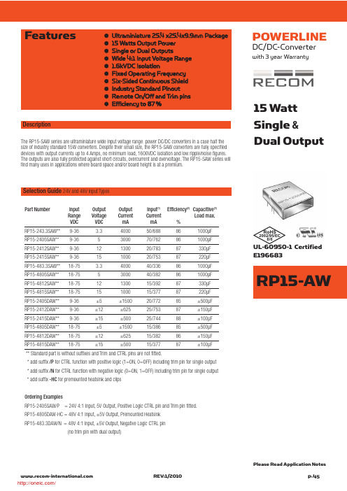
15 Watt Single &Dual Output●Ultraminiature 25.4 x25.4x9.9mm Package ●15 Watts Output Power ●Single or Dual Outputs●Wide 4:1 Input Voltage Range ●1.6kVDC Isolation●Fixed Operating Frequency ●Six-Sided Continuous Shield ●Industry Standard Pinout ●Remote On/Off and Trim pins ●Efficiency to 87%FeaturesSelection Guide 24V and 48V Input TypesPart NumberInput Output Output Input (1)Efficiency (2)Capacitive (3)Range Voltage Current Current Load max.VDC VDC mA mA %RP15-243.3SAW**9-36 3.3400050/688861000µF RP15-2405SAW**9-365300070/762861000µF RP15-2412SAW**9-3612130020/78387330µF RP15-2415SAW**9-3615100020/75387220µF RP15-483.3SAW**18-75 3.3400040/336861000µF RP15-4805SAW**18-755300040/382861000µF RP15-4812SAW**18-7512130015/39287330µF RP15-4815SAW**18-7515100015/37787220µF RP15-2405DAW**9-36±5±150020/77285±500µF RP15-2412DAW**9-36±12±62525/75387±150µF RP15-2415DAW**9-36±15±50025/74488±100µF RP15-4805DAW**18-75±5±150015/38685±500µF RP15-4812DAW**18-75±12±62515/38286±150µF RP15-4815DAW**18-75±15±50015/37787±100µF** Standard part is without suffixes and Trim and CTRL pins are not fitted.* add suffix /P for CTRL function with positive logic (1=ON, 0=OFF) including trim pin for single output * add suffix /N for CTRL function with negative logic (0=ON, 1=OFF) including trim pin f or single output * add suffix -HC for premounted heatsink and clips Ordering ExamplesRP15-2405SAW/P = 24V 4:1 Input, 5V Output, Positive Logic CTRL pin and Trim pin fitted.RP15-4805DAW-HC = 48V 4:1 Input, ±5V Output, Premounted Heatsink RP15-483.3DAW/N = 48V 4:1 Input, ±5V Output, Negative Logic CTRL pin(no trim pin with dual output)The RP15-SAW series are ultraminiature wide input voltage range power DC/DC converters in a case half the size of industry standard 15W converters. Despite their small size, the RP15-SAW converters are fully specified devices with output currents up to 4 Amps, no minimum load, 1600VDC isolation and low ripple/noise figures.The outputs are also fully protected against short circuits, overcurrent and overvoltage. The RP15-SAW series will find many uses in applications where board space and/or board height is at a premium.DescriptionPlease Read Application NotesUL-60950-1 Certified E196683REV:1/2010P-45 RP15-AWPOWERLINEDC/DC-Converterwith 3 year WarrantyRoHS2002/95/EC6/6/Input Voltage Range 24V nominal input 9-36VDC 48V nominal input18-75VDC Input FilterPi Type Input Surge Voltage (100 ms max.)24V Input 50VDC 48V Input 100VDC Input Reflected Ripple (nominal Vin and full load) (see Note 4)30mAp-p Start Up Time (nominal Vin and constant resistor load)30ms max.Optional Remote ON/OFF (See Note 5)DC-DC ON Short or 0V < Vr < 1.2V (Negative logic)DC-DC OFF Open or 3.0V < Vr < 12VRemote Pin drive current Nominal Vin -0.5mA~1.0mARemote OFF input currentNominal Vin 2.5mAOutput Voltage Accuracy (full Load and nominal Vin)±1%Optional Output Trim (see Note 5)±10%Minimum Load0%Line Regulation (low line, high line at full load)Single ±0.2%Dual ±0.5%Load Regulation (0% to full load)Single ±0.2%Dual ±1%Cross Regulation (Asymmetrical 25% <> 100% load)Dual Output ±5%Ripple and Noise (20MHz bandwith) 3.3, 5V Outputs 75mVp-p Others100mVp-p Temperature Coefficient±0.02%/°C max.Transient Response (25% load step change)250µs Over Voltage Protection3.3V 3.7-5.4V Zener diode clamp (only single)5V 5.4-7.0V 12V 13.5-19.6V 15V16.8-20.5V Over Load Protection (% of full load at nominal Vin)150% typUndervoltage Lockout See Application Notes Short Circuit Protection Hiccup, automatic recovery Efficiencysee …Selection Guide“ tableIsolation Voltage (rated for one minute)1600VDC Isolation Resistance 1 G Ωmin.Isolation Capacitance1000pF max.continued on next pageSpecifications (typical at nominal input and 25°C unless otherwise noted)Typical CharacteristicsDerating graphs are valid only for the shown part numbers. If you need detailed derating-information about a part-number not shown here please contact our technical support service at info@recom-development.at125755025100Ambient Temperature Range (°C)-40-10050708090100O u t p u t P o w e r (%)60Natural Convection-25125755025100Ambient Temperature Range (°C)-40-10050608090100O u t p u t P o w e r (%)66Natural Convection-2570RP15-4805SAWRP15-4805SAW With Heat SinkR P 15-A WREV: 1/2010P-46/Specifications (typical at nominal input and 25°C unless otherwise noted)Operating Frequency 400kHz typOperating Temperature Range -40°C to +85°C(with derating)Maximum Case Temperature +105°CStorage Temperature Range -55°C to +125°CThermal Impedance Natural convection18.2°C/Watt (see Note 6)Natural convection with Heat Sink15.8°C/Watt Thermal Shock MIL-STD-810FVibration 10-55Hz, 10G, 30 Min. along X, Y and ZRelative Humidity 5% to 95% RH Case Material Nickel plated copperBase Material FR4 PCB Potting MaterialEpoxy (UL94-V0)Conducted Emissions (see Note 7)EN55022Class A Radiated Emissions EN55022Class A ESDEN61000-4-2Perf. Criteria A Radiated Immunity EN61000-4-3Perf. Criteria A Fast Transient EN61000-4-4Perf. Criteria A Surge (see note 8)EN61000-4-5Perf. Criteria A Conducted Immunity EN61000-4-6Perf. Criteria AWeight 15gPacking Quantity Refer to App Notes for tube dimensions8 pcs per Tube Dimensions 25.4 x 25.4 x 9.9mmMTBF (see Note 9)Bellcore TR-NWT-0003321330 x 103hours MIL-HDBK 217F 563 x 103hours1. Values at nominal input voltage and no load/full load.2. Typical Value at nominal input voltage and full load.3.Test by minimum Vin and constant resistor load.4.Simulated source impedance of 12µH. 12µH inductor in series with +Vin.5.The ON/OFF control function can be positive or negative logic. The pin voltage is referenced to negative input.Positive logic ON/OFF is marked with suffix-P (eg. RP15-2405SAW/P)Negative logic ON/OFF is marked with suffix-N (eg. RP15-2405SAW/N).If no suffix is specified, the control pin will be omitted.6.Optional Heat-sink P/N is 7G-0047-C. Powerline DC/DC Converters can be ordered with pre-mounted heatsinks including antivibration fixing clips (add suffix -HC). See Application Notes for heatsink details.7. Meets Class A with external input capacitors shown below. Will meet Class B with external common mode filter (see Application Notes)8.Requires external capacitor to meet EN61000-4-5: 220µF/100V, low ESR (48mOhm)9.BELLCORE TR-NWT-000332. Case l: 50% Stress, Temperature at 40°C.MIL-HDBK 217F Notice 2. Ta = 25°C, full load, (Ground Benign, controlled environment).Notes :Trim UpRUTrim DownR D5654External Output Trimming (optional)With /CTRL suffix, output can be externally trimmed by using the method shown here. See Application Notes for details.REV:1/2010P-47 RP15-AW/Package Style and Pinning (mm)1.0 dia3rd angle projectionEMC Filtering - For Class B filter suggestion, see Application NotesClass A FilterVin=24V: C1=6.8µF/50V 1812 MLCC, C2 omitted.Vin=48V: C1, C2 = 2.2µF/100V 1812 MLCCTypical CharacteristicsPin Connections Pin #Single Single/Dual Dual/P or /N P or /N 1+Vin +Vin +Vin +Vin 2-Vin -Vin -Vin -Vin 3no pin CTRL no pin CTRL 4+Vout +Vout +Vout +Vout 5no pin Trim Com Com 6-Vout-Vout-Vout-VoutCase Tolerance ±0.5 mm Pin Pitch Tolerance ±0.25 mm301848Efficiency VS Input Voltage3642245460667072747678808284868890E f f i c i e n c y (%)Input Voltage (V)7225075Efficiency VS Output load 501004045505560657075808590Output Load (%)E f f i c i e n c y (%)RP15-4805SAWRP15-4805SAWR P 15-A WREV: 1/P-48/分销商库存信息:RECOM-POWERRP15-2412SAW RP15-2405SAW RP15-4812SAWRP15-483.3SAW RP15-243.3SAW RP15-4805SAWRP15-2415DAW RP15-4815DAW RP15-4812DAWRP15-2415SAW RP15-4815SAW RP15-2405SAW-HC RP15-2412SAW-HC RP15-2415SAW-HC RP15-243.3SAW-HC RP15-4805SAW-HC RP15-4812SAW-HC RP15-4815SAW-HC RP15-483.3SAW-HC RP15-2405SAW/N RP15-2405SAW/PRP15-2412SAW/N RP15-2412SAW/P RP15-2415SAW/NRP15-2415SAW/P RP15-243.3SAW/N RP15-243.3SAW/PRP15-4805SAW/N RP15-4805SAW/P RP15-4812SAW/NRP15-4812SAW/P RP15-4815SAW/N RP15-4815SAW/PRP15-483.3SAW/N RP15-483.3SAW/P RP15-2405DAWRP15-4805DAW RP15-2412DAW RP15-2405SAW/N-HC RP15-2405SAW/P-HC RP15-2412SAW/N-HC RP15-2412SAW/P-HC RP15-2415SAW/N-HC RP15-2415SAW/P-HC RP15-243.3SAW/N-HC RP15-243.3SAW/P-HC RP15-4805SAW/N-HC RP15-4805SAW/P-HC RP15-4812SAW/N-HC RP15-4812SAW/P-HC RP15-4815SAW/N-HC RP15-4815SAW/P-HC RP15-483.3SAW/N-HC RP15-483.3SAW/P-HC RP15-2405DAW-HC RP15-2412DAW-HC RP15-2415DAW-HC RP15-4805DAW-HC RP15-4812DAW-HC RP15-4815DAW-HC RP15-2405DAW/N RP15-2405DAW/P RP15-2412DAW/NRP15-2412DAW/P RP15-2415DAW/N RP15-2415DAW/PRP15-4805DAW/N RP15-4805DAW/P RP15-4812DAW/NRP15-4812DAW/P RP15-4815DAW/N RP15-4815DAW/PRP15-2405DAW/N-HC RP15-2405DAW/P-HC RP15-2412DAW/N-HC RP15-2412DAW/P-HC RP15-2415DAW/N-HC RP15-2415DAW/P-HC RP15-4805DAW/N-HC RP15-4805DAW/P-HC RP15-4812DAW/N-HC RP15-4812DAW/P-HC RP15-4815DAW/N-HC RP15-4815DAW/P-HC。
2412无刷电机规格书
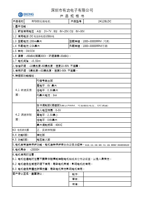
深圳市有功电子有限公司产 品 规 格 书产品名称RF300无刷电机产品型号2412BLDC 1.基本性能:1.1 额定使用电压:A型:2V~7V;B型:6V~20V; C型:6V~30V.1.2 使用电源:DC 电池供电或USB供电1.3 空载电流:200m A最大空载转速:1000~30000RPM(可调)1.4 负载电流:2.0A最大负载转速:1000~30000RPM(可调) 1.5 转向:CW/CCW1.6 噪音:<60d B A(距离30C M,环境噪音<30d B A)。
1.7 电机间隙:<0.55mm2.存储环境:-10摄氏度-60摄氏度,湿度10-90% 不凝露。
3.使用环境:5摄氏度-+50摄氏度,湿度0-90% 不凝露。
4.接插脚功能描述:4.1转速反馈脚:F G信号输出脚高电平:6V 最大低电平:0.6V最大F G最大电流:3m A4.2调速控制脚:脉冲调制脚(调速脚)(默认PWM,可选模拟电压、I2C调速)输入电压范围:0-5V高电平:2.5V最小低电平:0.6V最大最大调制频率:40K H Z4.3 电机转向脚 正、反转控制脚4.4 功能4脚:接地脚4.5 功能5脚:电压输入脚5.电机自带堵转保护功能,电机堵转保护后会自动重启运转。
具过流、过压、反接、缺相、欠压、过温、堵转保护(具体请咨询供应商)6.电机寿命: >20000H6.电机使用时注意:6.1 电机在通电时注意不要身体触摸或接触电机轴或其它传动装置,以免人身受伤。
6.2 电机避免在潮湿环境下使用,导致电机受潮,影响电机的使用。
6.3 电机避免受撞击跌落伤害,导致电机受伤影响电机使用。
客户承认签名,盖章确认:制作:审核:核准:深圳市有功电子有限公司M o d e l Vo l t a g e N o I o a d A t m a x i m u m E f f i c i e n t S t a l l O p e r a t i n g R a n g e (V ) M o m i n a I (V ) S p e e d C u r r e n t S p e e d C u r r e n t R a t e d L o a d O u t p u t To r q u e C u r r e n t R P M m A R P M m A g f. c m m N.M W g f.c m m N. m A I E M -300L H 1.8V-7V 5.0V 8000 120 7500 320 18.35 1.8 1.6 158 15.52000I E M - 300H F6V-20V 12V 17000 150 15300 590 41.8 4.1 7.1 174.317.11800I E M -300VA 6V-30V 12V 9900 75 8000 320 41.3 4.05 3.84 201.919.81020 更多规格可定制,请提供需求参数。
2SC2412 二极管 数据手册

Transistors 2SC5658 / 2SC1740SGeneral purpose transistor (50V, 0.15A)2SC2412K / 2SC4081 / 2SC4617 / 2SC5658 /2SC1740S!Features 1) Low Cob.Cob=2.0pF (Typ.)2) Complements the 2SA1037AK /2SA1576A / 2SA1774H /2SA2029 / 2SA933AS.!StructureEpitaxial planar type NPN silicon transistor!External dimensions (Units : mm)* Denotes h FE!Absolute maximum (T a=25°C)Collector-base voltage Collector-emitter voltage Emitter-base voltage Collector currentCollector powerdissipationJunction temperature Storage temperatureParameterV CBO V CEO V EBO P CTj Tstg60V V V AW °C °C 5070.15I C0.20.150.32SC2412K, 2SC40812SC1740S 2SC4617, 2SC5658150−55~+150Symbol Limits UnitTransistors 2SC5658 / 2SC1740S!Electrical characteristics (T a=25°C)Collector-base breakdown voltage Collector-emitter breakdown voltage Emitter-base breakdown voltage Collector cutoff current Emitter cutoff current DC current transfer ratioCollector-emitter saturation voltage Output capacitanceParameterSymbol BV CBO BV CEO BV EBO I CBO I EBO h FE V CE(sat)f T CobMin.60507−−120−−−−−−−−−−1802−−−0.10.15600.4−3.5V I C =50µA I C =1mA IE =50µA V CB =60V V EB =7VV CE =6V, I C =1mA I C /I B =50mA/5mAV CE =12V, I E =−2mA, f=100MHz V CE =12V, I E =0A, f=1MHzV V µA µA −V MHz pFTyp.Max.Unit ConditionsTransition frequency !Packaging specifications and h FEh FE values are classified as follows :Item Q R S h FE120~270180~390270~560!Electrical characterristic curvesFig.1 Grounded emitter propagationcharacteristics C O L L E C T O R C U R R E N T: I C (m A )BASE TO EMITTER VOLTAGE : V BE (V)Fig.2 Grounded emitter outputcharacteristics ( Ι )C O L L E C T O R C U R R E N T : I C (m A )COLLECTOR TO EMITTER VOLTAGE : V CE (V)C O L L E C T O R C U R R E N T : I C (m A )COLLECTOR TO EMITTER VOLTAGE : V CE (V)Fig.3 Grounded emitter outputcharacteristics ( ΙΙ )Transistors2SC5658 / 2SC1740SFig.4 DC current gain vs.collector current ( Ι )D C C U R RE N T G A I N: h F ECOLLECTOR CURRENT : I C (mA)Fig.5 DC current gain vs.collector current ( ΙΙ )D C C U R R E N T G A I N : h F ECOLLECTOR CURRENT : I C (mA)Fig. 6 Collector-emitter saturationvoltage vs. collector currentC O L L E C T O R S A T U R A T I O N V O L T A G E : V C E (s a t ) (V )COLLECTOR CURRENT : I C (mA)Fig.7 Collector-emitter saturation voltage vs. collector current ( Ι )C O L L E C T O R S A T U R A T I O N V O L T A G E : V C E (s a t ) (V )COLLECTOR CURRENT : I C (mA) Fig.8 Collector-emitter saturationvoltage vs. collector current (ΙΙ)C O L L E C T O R S A T U R A T I O N V O L T A G E : V C E (s a t ) (V )COLLECTOR CURRENT : I C (mA)Fig.9 Gain bandwidth product vs.emitter current−EMITTER CURRENT : I E (mA)T R A N S I T I O N F R E Q U E N C Y : f T (M H z )Fig.10 Collector output capacitance vs.collector-base voltageEmitter input capacitance vs.emitter-base voltageCOLLECTOR TO BASE VOLTAGE : V CB (V)EMITTER TO BASE VOLTAGE : V EB (V)C O L L E C T O R O U T P U T C A P A CI T A N C E : C o b (p F )E M I T T E R I N P U T C A P A C I T A N C E : C i b (p F )Fig.11 Base-collector time constantvs. emitter current− B A S E C O L L E C T O R T I M E C O N S T A N T : C c ·r b b (p s )EMITTER CURRENT : I E (mA)。
飞利浦 显示器241S4 ZH 用户手册说明书
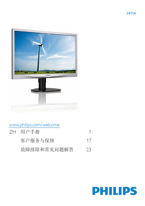
/welcome 241S4ZH 用户手册 1 客户服务与保修17故障排除和常见问题解答23目录1. 重要 (1)1.1 安全措施与维修 (1)1.2 标志说明 (2)1.3 产品和包装材料的废弃 (3)2. 设置显示器 (4)2.1 安装 (4)2.2 操作显示器 (6)2.3 卸下底座装置 (9)3. 图像优化 (11)3.1 SmartImage (11)3.2 SmartContrast (12)4. 技术规格 (13)4.1 分辨率和预设模式 (15)5. 电源管理 (16)6. 客户服务与保修 (17)6.1 飞利浦平板显示器像素缺陷规定 (17)6.2 客户服务与保修 (19)7. 故障排除和常见问题解答 (23)7.1 故障检修 (23)7.2 一般常见问题解答 (24)1. 重要此电子版用户指南适合使用 Philips 显示器的所有用户。
请在使用您的显示器之前花点时间阅读本 User Manual (用户手册) 。
它包含与使用显示器相关的重要信息和注意事项。
产品享受飞利浦保修须符合下列条件:产品适当用于其设计目的、符合操作说明、返修时提供原始帐单或付款收据,帐单或收据应载明购货日期、销售商名称、产品型号及生产号。
1.1 安全措施与维修警告使用本文档中未介绍的控制、调整或过程可能导致碰撞、电气危险和/或机械危险。
连接和使用电脑显示器时,请阅读并遵循以下说明。
操作:• 请使显示器远离阳光直接照射、明亮强光线、以及任何其他热源。
长期暴露于此类环境可能导致显示器褪色和损坏。
• 移开任何可能掉入通风孔的物品或者会妨碍显示器电子器件正常冷却的物品。
• 请勿堵塞机壳上的通风孔。
• 放置显示器时,确保电源插头和插座便于插拔。
• 如果通过拔掉电源线或直流电源线关闭显示器电源,则在重新连接电源线或直流电源线以进行正常操作之前,必须等待 6 秒钟。
• 请务必使用由 Philips 提供的经过认可的电源线。
低分子肝素和利伐沙班在髋膝关节置换中的应用
and㈣ytic n蝴
v日∞us Proc,2005;80(6):
Nuts.2001;15(4):25-44
thromboembolism:
Jaffer AK.13arsoum WK.KreIx,V。et aL
Duration of anesthesia and
venous
thrtmalxena】0lism aftel"hip and knee arthroptasty.Mayo Clin
前使用LMWH可增加全髋和全膝关节置换手术的总失 血量和隐性失血量,LMWH使用时机对术后D.vT发生 率无影响,术后使用LMWH更安全。RF_Lx)RD 1、2、3试 验研究中依诺肝素均在术前使用,这是否会增加相关出 血事件,进而影响结果的正确性,还需进一步研究。 总之,LMwH用于髋膝关节置换可有效预防静脉 血栓形成,引起出血、HIT及骨质疏松的风险相对较低, 具有较好的安全性。利伐沙班作为一种凝血因子X a直 接抑制剂,具有口服方便、剂量固定、起效快速(给药后
~6 h开始给予常规剂量的一半,次日增加至常规剂
DVT危险因素和诊断 静脉血流减慢(或淤滞)、血液高凝状态和血管内皮
损伤是DVT形成的主要原因[2]。根据骨科大手术患者 并发血栓形成的危险分层[3],髋关节和膝关节置换手术 属于极高危组,极容易引起血栓形成。另外,手术过程中 的麻醉H],既往有静脉血栓栓塞史,以及肥胖、下肢静脉 曲张、糖尿病、慢性静脉炎、心血管疾病等,均是DVT的 高危因素‘5|。
2 3
Aqulia
Geel-ts the
AM【hp
WH.Pineo
re.otis
throml础J Cardiovasc
Antithronalxrdc
2SC2412二极管数据手册

2SC2412二极管数据手册Transistors 2SC5658 / 2SC1740SGeneral purpose transistor (50V, 0.15A)2SC2412K / 2SC4081 / 2SC4617 / 2SC5658 /2SC1740S!Features 1) Low Cob.Cob=2.0pF (Typ.)2) Complements the 2SA1037AK /2SA1576A / 2SA1774H /2SA2029 / 2SA933AS.!StructureEpitaxial planar type NPN silicon transistor!External dimensions (Units : mm)* Denotes h FE!Absolute maximum (T a=25°C)Collector-base voltage Collector-emitter voltage Emitter-base voltage Collector currentCollector powerdissipationJunction temperature Storage temperatureParameterV CBO V CEO V EBO P CTj Tstg60V V V AW °C °C 5070.15I C0.20.150.32SC2412K, 2SC40812SC1740S 2SC4617, 2SC5658150?55~+150Symbol Limits UnitTransistors 2SC5658 / 2SC1740S!Electrical characteristics (T a=25°C)Collector-base breakdown voltage Collector-emitter breakdown voltage Emitter-base breakdown voltage Collector cutoff current Emitter cutoff current DC current transfer ratio Collector-emitter saturation voltage Output capacitanceParameterSymbol BV CBO BV CEO BV EBO I CBO I EBO h FE V CE(sat)f T CobMin.60507??12018020.10.15600.4?3.5V I C =50μA I C =1mA IE =50μA V CB =60V V EB =7VV CE =6V, I C =1mA I C /I B =50mA/5mAV CE =12V, I E =?2mA, f=100MHz V CE =12V, I E =0A, f=1MHzV V μA μA ?V MHz pFTyp.Max.Unit ConditionsTransition frequency !Packaging specifications and h FEh FE values are classified as follows :Item Q R S h FE120~270180~390270~560!Electrical characterristic curvesFig.1 Grounded emitter propagationcharacteristics C O L L E C T O R C U R R E N T: I C (m A )BASE TO EMITTER VOLTAGE : V BE (V)Fig.2 Grounded emitter outputcharacteristics ( Ι )C O L L E C T O R C U R R E N T : I C (m A )COLLECTOR TO EMITTER VOLTAGE : V CE (V)C O L L E C T O R C U R R E N T : I C (m A )COLLECTOR TO EMITTER VOLTAGE : V CE (V)Fig.3 Grounded emitter outputcharacteristics ( ΙΙ )Transistors2SC5658 / 2SC1740SFig.4 DC current gain vs.collector current ( Ι )D C C U R RE N T G A I N: h F ECOLLECTOR CURRENT : I C (mA)Fig.5 DC current gain vs.collector current ( ΙΙ )D C C U R R E N T G A I N : h F ECOLLECTOR CURRENT : I C (mA)Fig. 6 Collector-emitter saturationvoltage vs. collector currentC O L L E C T O R S A T U R A T I O N V O L T A G E : V C E (s a t ) (V )COLLECTOR CURRENT : I C (mA)Fig.7 Collector-emitter saturation voltage vs. collector current ( Ι )C O L L E C T O R S A T U R A T I O N V O L T A G E : V C E (s a t ) (V )COLLECTOR CURRENT : I C (mA) Fig.8 Collector-emitter saturationvoltage vs. collector current (ΙΙ)C O L L E C T O R S A T U R A T I O N V O L T A G E : V C E (s a t ) (V )COLLECTOR CURRENT : I C (mA)Fig.9 Gain bandwidth product vs.emitter currentEMITTER CURRENT : I E (mA)T R A N S I T I O N F R E Q U E N C Y : f T (M H z )Fig.10 Collector output capacitance vs.collector-base voltageEmitter input capacitance vs.emitter-base voltageCOLLECTOR TO BASE VOLTAGE : V CB (V)EMITTER TO BASE VOLTAGE : V EB (V)C O L L E C T O R O U T P U T C A P A CI T A N C E : C o b (p F )E M I T T E R I N P U T C A P A C I T A N C E : C i b (p F )Fig.11 Base-collector time constantvs. emitter currentB A S EC O L L E C T O R T I M E C O N S T A N T : C c ·r b b (p s )EMITTER CURRENT : I E (mA)。
Dell UltraSharp U2412M U2412MWh 显示器使用指南说明书
Dell™ UltraSharp U2412M/U2412MWh 顯示器使用指南(User Guide)將顯示解析度設為 1920 x 1200 (最大) 的重要指示.此文件中的資訊如有變更,恕不另行通知。
© 2011-2019 Dell Inc. All rights reserved.嚴格禁止在未獲得Dell Inc.書面同意的情況下以任何方式重製任何部分。
本文中使用的商标:Dell 和DELL 標誌是 Dell Inc. 的商標;Microsoft 和Windows 是 Microsoft Corporation 在美國及/或其它國家的商標或注冊商標;Intel 是 Intel Corporation 在美國及其它國家的注冊商標;ATI 是 Advanced Micro Devices, Inc. 的商標; ENERGY STAR 是美國環保署的注冊商標。
作為 ENERGY STAR 合作夥伴,Dell Inc. 認定本產品符合 ENERGY STAR 能效方面的標準。
此文件中可能會使用其它商標與商品名稱來參照聲稱的標誌與名稱或其產品的實體。
Dell Inc.放棄除了其自己的商標與商品名稱以外的任何商標與商品名稱的所有利益。
型號 U2412Mb/U2412Mc2019年3月版本 A13回到內容頁安裝您的顯示器Dell™ UltraSharp U2412M/U2412MWh 顯示器將顯示解析度設為 1920 x 1200 (最大) 的重要指示為了在使用 Microsoft® Windows® 作業系統時取得最大的顯示器效能,請執行下列步驟將顯示解析度設定為1920 x 1200像素:在 Windows Vista®、Windows® 7、Windows® 8 、Windows® 8.1 中:1.僅適用於 Windows® 8 和 Windows® 8.1,選取「桌面動態磚」以切換至傳統桌面。
Dell UltraSharp U2412M U2412MWh 显示器 用户指南说明书
Dell™ UltraSharp U2412M/U2412MWh 显示器用户指南将显示分辨率设置为 1920 x 1200(最大)的重要说明本文档中的信息会随时变更,恕不另行通知。
©2011-2020 Dell Inc. 保留所有权利。
未经 Dell Inc. 书面许可,严禁以任何形式复制本文档之内容。
本文中使用的商标:Dell和 DELL标志是 Dell Inc. 的商标;Microsoft 和 Windows 是 Microsoft Corporation 在美国及/或其它国家的商标或注册商标;Intel 是 Intel Corporation 在美国及其它国家的注册商标;ATI 是 Advanced Micro Devices, Inc. 的商标; ENERGY STAR是美国环保署的注册商标。
作为 ENERGY STAR 合作伙伴,Dell Inc. 认定本产品符合 ENERGY STAR 能效方面的标准。
本文中用到的其它商标和品牌名称均属其各自拥有人所有。
Dell Inc. 对于自己之外的商标和品牌名称没有任何专有利益。
型号 U2412M2020年1月 Rev. A14返回目录页设置显示器Dell™ UltraSharp U2412M/U2412MWh 显示器将显示分辨率设置为 1920 x 1200 (最大) 的重要说明要在使用 Microsoft® Windows®操作系统时获得最大显示性能,请按照以下步骤将显示分辨率设置为1920 x 1200像素:在 Windows Vista®、Windows® 7、Windows® 8、Windows® 8.1:1.仅适用于 Windows® 8 和 Windows® 8.1,选择桌面平铺以切换到经典桌面。
2.在桌面上右击并选择屏幕分辨率。
3.单击“屏幕分辨率”的下拉列表并选择1920 x 1200。
阿尔卡特2412用户手册说明书

3.5 MUTE
l Press the Mute key. Your correspondent can no longer hear you during this waiting
BEEP
time. l 1 beep is generated on the line every 10 seconds.
4. USING THE MEMORIES
NOTE: When programming your TEMPORIS communicates with you using BEEP . 1 Beep : Whilst programming, each key pressed is validated by 1 BEEP . 2 Beeps : Indicate that your programming is correct. 3 Beeps : Something is wrong in your programming; Restart from the beginning.
3.3 LOUDSPEAKER KEY*
During a call, press the Loudspeaker key so that the people around you can hear the conversation. l Adjust the sound level with the and keys.
l To resume the conversation, press the Mute key again.
3.6 LAST NUMBER REDIAL l Go off hook. l Press the Last Number Redial key.
To erase the last number redial l Go off hook. l Press the Programming key twice. l Press the Last Number Redial key.
EUROLIGHT LC2412 快速启动指南说明书
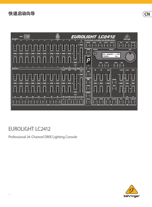
EUROLIGHT LC2412Professional 24-Channel DMX Lighting Console V 1.0带有此标志的终端设备具有强大的电流, 存在触电危险。
仅限使用带有 ¼'' TS 或扭锁式插头的高品质专业扬声器线。
所有的安装或调整均须由合格的专业人员进行。
此标志提醒您, 产品内存在未绝缘的危险电压, 有触电危险。
此标志提醒您查阅所附的重要的使用及维修说明。
请阅读有关手册。
小心为避免触电危险, 请勿打开机顶盖 (或背面挡板)。
设备内没有可供用户维修使用的部件。
请将维修事项交由合格的专业人员进行。
小心为避免着火或触电危险, 请勿将此设备置于雨淋或潮湿中。
此设备也不可受液体滴溅, 盛有液体的容器也不可置于其上, 如花瓶等。
小心维修说明仅是给合格的专业维修人员使用的。
为避免触电危险, 除了使用说明书提到的以外, 请勿进行任何其它维修。
所有维修均须由合格的专业人员进行。
1. 请阅读这些说明。
2. 请妥善保存这些说明。
3. 请注意所有的警示。
4. 请遵守所有的说明。
5. 请勿在靠近水的地方使用本产品。
6. 请用干布清洁本产品。
7.请勿堵塞通风口。
安装本产品时请遵照厂家的说明。
8. 请勿将本产品安装在热源附近,如 暖 气 片, 炉子或其它产生热量的设备 ( 包 括功放器)。
9. 请勿移除极性插头或接地插头的安全装置。
接地插头是由两个插塞接点及一个接地头构成。
若随货提供的插头不适合您的插座, 请找电工更换一个合适的插座。
10. 妥善保护电源线, 使其不被践踏或刺破, 尤其注意电源插头、多用途插座及设备连接处。
11. 请只使用厂家指定的附属设备和配 件。
12. 请只使用厂家指定的或随货销售的手推车, 架子, 三 角架, 支架和桌子。
若使用手推车来搬运设备, 请注意安全放置设备, 以 避免手推车和设备倾倒而受伤。
13. 遇闪电雷鸣或长期不使用本设备时,请 拔出电源插头。
RECOM 电源 RSE 系列 2W 隔离 DC DC 转换器 产品说明书
REV.: 3/2019ECO-1Regulated • 2:1 Wide input range • 2kVDC/1 Second isolation• -40°C To +75°C Operating temperature @ full load • Industry standard pinout (SIP8)• EN/UL62368 and UL60950 certified, CB report • Low cost RSEDescriptionThe RSE is a low cost isolated, regulated and short-circuit protected DC/DC converter designed forDC/DC Convert er2 WattE224736UL62368-1 certifiedC22.2 No. 62368-1-14 certfied UL60950 certifiedC22.2 No. 60950-1-07 certified IEC/EN62368-1 certified EN55032/55024 compliant CB ReportFeaturesConverters• 2:1 Wide input range • 2kVDC/1 second isolation -40°C to +75°C operating temperature @ full load • EN/UL62368 and UL60950 certified, CB report • Low costBASIC CHARACTERISTICSParameterCondition Min.Typ.Max.Internal Input Filter capacitor Input Voltage Range nom. Vin=5VDC 24VDC4.5VDC 18VDC5VDC 24VDC9VDC 36VDC Maximum Reverse Voltage 0VDCInput Surge Voltage 100ms max nom. Vin=5VDC 24VDC 15VDC 50VDC Quiescent Current nom. Vin=5VDC 24VDC40mA 3mA Start-up time 500µs Rise time 450µs Hold-up time10µsInternal Operating Frequency 130kHz Minimum Load0%Output Ripple and Noise (3)20MHz BW, 0-100% load75mVp-pON/OFF CTRL (4)DC-DC ON DC-DC OFF Open or 0V<Vr<0.8VDC2V<Vr<6VDC Input Current of CTRL Pin 5V V CTRL 3.3V V CTRL15mA 10mA Standby Current0.75mA1.5mAcontinued on next pageNotes:Note3: Measurements are made with a 0.1µF MLCC across output (low ESR) Note4: Please refer to …Application and Installation“Specifications (measured @ ta= 25°C, nominal Vin, full load unless otherwise specified)REV.: 3/2019ECO-2Specifications (measured @ Ta= 25°C, nominal Vin, full load unless otherwise specified)PROTECTIONSParameterTypeValueShort Circuit Protection (SCP)below 100m Wcontinuous, auto recoveryIsolation Voltage (5)I/P to O/Ptested for 1 second2kVDC Isolation Resistance 1G W min.Isolation Capacitance 100pF max.Insulation Gradefunctionalcontinued on next pageREGULATIONSParameterConditionValueOutput Accuracy 0-100% load ±2.0% max.Line Regulation low line to high line, full load±0.2% max.Load Regulation0% to 100% load±0.5% max.RSE-0505S/H2RSE-2405S/H2Accuracy vs. LoadA c c u r a c y [%]Output Current [A]000.20.10.30.40.50.60.10.20.30.4A c c u r a c y [%]Output Current [A]000.10.20.30.40.50.10.20.30.4REV.: 3/2019ECO-3Specifications (measured @ Ta= 25°C, nominal Vin, full load unless otherwise specified)ENVIRONMENTALParameterConditionValueOperating Temperature Range without derating (see graph)-40°C to +75°CMaximum Case Temperature +105°C Temperature Coefficient ±0.05%/°COperating Altitude 5000mOperating Humidity non-condensing5% - 95% RH max.Pollution Degree PD2MTBF according to MIL-HDBK-217F, G.B.+25°C +75°C2289 x 103 hours 781 x 103 hours VibrationMIL-STD 202G100806040200-4005075100150O u t p u t P o w e r [%]Ambient Temperature [°C]Derating Graph(@ Chamber and natural convection 0.1m/s)SAFETY AND CERTIFICATIONSCertificate Type (Safety)Report / File NumberStandard Information Technology Equipment, General Requirements for Safety E224736-A48UL60950-1, 2nd Edition, 2014CSA C22.2 No. 60950-1-07, 2nd Ed. 2014Audio/Video, information and communication technology equipment - Safety requirementsUL62368-1, 2nd Edition, 2014CSA C22.2 Nr. 62368-1-14, 2nd Ed. 2014Audio/Video, information and communication technology equipment - Safety requirements (CB Scheme)L0339m37-CB-1-B1IEC/EN62368-1, 2nd Edition, 2014RoHS 2+RoHS 2011/65/EU + AM2015/863continued on next pageSpecifications(measured @ Ta= 25°C, nominal Vin, full load unless otherwise specified)DIMENSION and PHYSICAL CHARACTERISTICSParameter Type ValueMaterialcasepottingPCBnon-conductive black plastic (UL94V-0)epoxy (UL94V-0)FR4 (UL94V-0)Dimension (LxWxH)21.8 x 9.2 x 11.1mm Weight 4.7g typ.continued on next pageC3 REV.: 3/2019ECO-4Specifications(measured @ Ta= 25°C, nominal Vin, full load unless otherwise specified)PACKAGING INFORMATIONPackaging Dimension (LxWxH)tube520.0 x 11.2 x 18.2mm Packaging Quantity22pcs Storage Temperature Range-55°C to +125°C Storage Humidity non-condensing5% - 95% RH max.The product information and specifications may be subject to changes even without prior written notice.The product has been designed for various applications; its suitability lies in the responsibility of each customer. The products are not authorized for use in safety-critical applications without RECOM’s explicit written consent. A safety-critical application is an application where a failure may reasonably be expected to endanger or cause loss of life, inflict bodily harm or damage property. The applicant shall indemnify and hold harmless RECOM, its affiliated companies and its representatives against any damage claims in connection with the unauthorizeduse of RECOM products in such safety-critical applications. REV.: 3/2019ECO-5。
- 1、下载文档前请自行甄别文档内容的完整性,平台不提供额外的编辑、内容补充、找答案等附加服务。
- 2、"仅部分预览"的文档,不可在线预览部分如存在完整性等问题,可反馈申请退款(可完整预览的文档不适用该条件!)。
- 3、如文档侵犯您的权益,请联系客服反馈,我们会尽快为您处理(人工客服工作时间:9:00-18:30)。
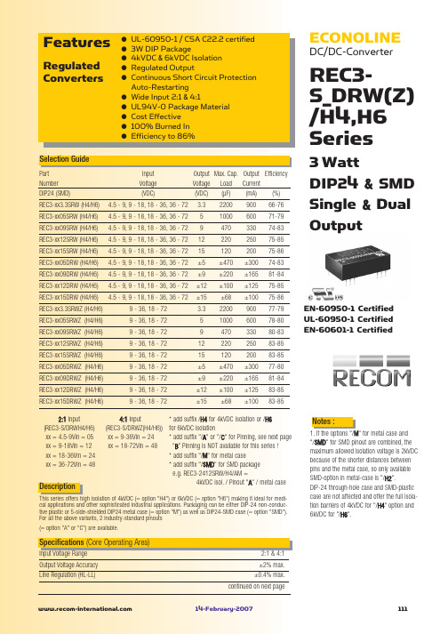
REC3-S_DRW(Z) /H4,H6 Series
±0.6% max. 50mVp-p max. 90kHz min. / 150kHz max. 120kHz min. / 180kHz max. Pi Network see above
Output Power (%)
Derating-Graph
Selection Guide
Part Number DIP24 (SMD) REC3-xx3.3SRW (H4/H6) REC3-xx05SRW (H4/H6) REC3-xx09SRW (H4/H6) REC3-xx12SRW (H4/H6) REC3-xx15SRW (H4/H6) REC3-xx05DRW (H4/H6) REC3-xx09DRW (H4/H6) REC3-xx12DRW (H4/H6) REC3-xx15DRW (H4/H6) REC3-xx3.3SRWZ (H4/H6) REC3-xx05SRWZ (H4/H6) REC3-xx09SRWZ (H4/H6) REC3-xx12SRWZ (H4/H6) REC3-xx15SRWZ (H4/H6) REC3-xx05DRWZ (H4/H6) REC3-xx09DRWZ (H4/H6) REC3-xx12DRWZ (H4/H6) REC3-xx15DRWZ (H4/H6) 2:1 Input (REC3-S/DRWH4/H6) xx = 4.5-9Vin = 05 xx = 9-18Vin = 12 xx = 18-36Vin = 24 xx = 36-72Vin = 48 Input Voltage (VDC) 4.5 - 9, 9 - 18, 18 - 36, 36 - 72 4.5 - 9, 9 - 18, 18 - 36, 36 - 72 4.5 - 9, 9 - 18, 18 - 36, 36 - 72 4.5 - 9, 9 - 18, 18 - 36, 36 - 72 4.5 - 9, 9 - 18, 18 - 36, 36 - 72 4.5 - 9, 9 - 18, 18 - 36, 36 - 72 4.5 - 9, 9 - 18, 18 - 36, 36 - 72 4.5 - 9, 9 - 18, 18 - 36, 36 - 72 4.5 - 9, 9 - 18, 18 - 36, 36 - 72 9 - 36, 18 - 72 9 - 36, 18 - 72 9 - 36, 18 - 72 9 - 36, 18 - 72 9 - 36, 18 - 72 9 - 36, 18 - 72 9 - 36, 18 - 72 9 - 36, 18 - 72 9 - 36, 18 - 72 Output Max. Cap. Output Efficiency Voltage Load Current (VDC) (µF) (mA) (%) 3.3 5 9 12 15 ±5 ±9 ±12 ±15 3.3 5 9 12 15 ±5 ±9 ±12 ±15 2200 1000 470 220 120 ±470 ±220 ±100 ±68 2200 1000 470 220 120 ±470 ±220 ±100 ±68 900 600 330 250 200 ±300 ±165 ±125 ±100 900 600 330 250 200 ±300 ±165 ±125 ±100
ECONOLINE
DC/DC-Converter
REC3S_DRW(Z) /H4,H6 Series
66-76 71-79 74-83 75-85 75-86 74-83 81-84 75-85 75-86 77-79 78-80 80-83 83-85 83-85 77-80 81-84 83-85 83-85
Typical Characteristics
Single 2:1 Input Single 2:1 Input
Efficiency / Load
100 80 60 40
Safe Operating Area
100 50 75 125 80 105 Operating Temperature (°C) 0 25
Output Power (%)
-55°C to +125°C 95% RH Non-Conductive Plastic 20°C/W for metal case 13g 1043 x 10 hours 186 x 103 hours
Specifications (Core Operating Area)
Input Voltage Range Output Voltage Accuracy Line Regulation (HL-LL) 2:1 & 4:1 ±2% max. ±0.4% max. continued on next page
(Ambient Temperature)
120 100 80 60 50 40 20 0 -40
Vin = 5V
300mW max. 4000VDC min. see Application Notes 6000VDC min. see Application Notes 20pF min. / 60pF max. 40pF min. / 80pF max. 1 GΩ min. Continuous, Auto Restart -40°C to +80°C (see Graph) -40°C to +85°C (see Graph)
3 Watt DIP24 & SMD Single & Dual Output
EN-60950-1 Certifi601-1 Certified
Description
4:1 Input * add suffix /H4 for 4kVDC isolation or /H6 (REC3-S/DRWZ(H4/H6)) for 6kVDC isolation xx = 9-36Vin = 24 * add suffix "/A" or "/C" for Pinning, see next page xx = 18-72Vin = 48 “B” Pinning is NOT available for this series ! * add suffix "/M" for metal case * add suffix "/SMD" for SMD package e.g. REC3-2412SRW/H4/AM = 4kVDC isol. / Pinout "A" / metal case
14-February-2007
111
元器件交易网
ECONOLINE
DC/DC-Converter
Specifications (Core Operating Area)
Load Regulation (for output load current change from 20% to 100%) Output Ripple and Noise (0,1µF capacitor on output, 20MHz BW) Switching Frequency at Full Load 2:1 Input types and nominal Input Voltage 4:1 Input types Input Filter Efficiency at Full Load No Load Power Consumption Isolation Voltage Rated Working Voltage Isolation Voltage Rated Working Voltage Isolation Capacitance Isolation Resistance Short Circuit Protection Operating Temperature Range (free air convection) Storage Temperature Range Relative Humidity Case Material Thermal Impedance Package Weight MTBF (+25°C) (+85°C) Natural convection using MIL-HDBK 217F using MIL-HDBK 217F 5V input types others H4 types (see note) H6 types (see note) (tested for 1 second) (long term isolation) (tested for 1 second) (long term isolation) 2:1 Input types 4:1 Input types
3
}
Detailed Information see Application Notes chapter "MTBF"
120 100 80 60 50 40 20 0 -40
Safe Operating Area
0
25
50 75
100 85 105
125
Operating Temperature (°C)
Notes :
1. If the options "/M" for metal case and "/SMD" for SMD pinout are combined, the maximum allowed isolation voltage is 2kVDC because of the shorter distances between pins and the metal case, so only available SMD-option in metal-case is "/H2". DIP-24 through-hole case and SMD-plastic case are not affected and offer the full isolation barriers of 4kVDC for "/H4" option and 6kVDC for "/H6".
