EFD---MINAC(SINAC) - 电子板卡介绍
Micro-KNC原理图

Micro-KNC火焰切割控制系统电器原理图上海康普数控技术设备有限公司2010-5目录-控制器面板示意图------------------------------------------------------------------------------------------------------------------------------------------------------3 -主回路电器原理图------------------------------------------------------------------------------------------------------------------------------------------------------4 -面板升降开关原理图---------------------------------------------------------------------------------------------------------------------------------------------------5 -割炬开关原理图(一)------------------------------------------------------------------------------------------------------------------------------------------------6 -割炬开关原理图(二)------------------------------------------------------------------------------------------------------------------------------------------------7 -继电器驱动原理图------------------------------------------------------------------------------------------------------------------------------------------------------8 -CNC输入输出接口接线图--------------------------------------------------------------------------------------------------------------------------------------------9 -连接头/座一览表--------------------------------------------------------------------------------------------------------------------------------------------------------10 -CNC伺服电机接口配线图-双边(供参考)----------------------------------------------------------------------------------------------------------------------11 -CNC伺服电机接口配线图-单边(供参考)----------------------------------------------------------------------------------------------------------------------12 -伺服电机驱动接口配线图(供参考)------------------------------------------------------------------------------------------------------------------------------13控制器面板示意图L N主回路电器原理图(一)5/125/95/115/105/45/15/35/25/85/55/75/6面板升降开关原理图6/46/16/36/2(P8)(P42/32/22/44/34/6割炬开关原理图(一)2/84/24/54/84/112/72/92/14/94/124/12/54/44/74/102/66/56/6继电器板1Z ,DB25继电器板2Z ,DB25CNC 输入输出接口接线图功能线号SY PY SRDYY 12V 0V 12V S1XSRDY1XSRDY2X P1X 3/143/113/133/123/153/103/23/13/93/73/83/43/33/53/63#连接头/座3LZT0V 功能线号H1XW1XW2La1H PE PE1/21/11/91/71/81/41/31/51/61#连接头/座1LZTLa2E 连接头/座一览表颜色红粉橙紫灰双色红黄双色功能线号预热H 快氧割炬1La2预热割炬2穿孔32/22/12/92/72/82/42/32/52/62#连接头/座2LZT穿孔1穿孔2颜色红粉橙黄绿兰紫灰白颜色粉黑黄红兰粉黑黑黑兰黄红兰功能线号4/114/124/104/24/14/94/74/84/44/34/54/64#连接头/座4LZT颜色棕红粉橙黄绿兰淡兰紫灰白黑快氧1点火2预热2点火1预热1快氧2点火3预热3快氧3点火4预热4快氧4功能线号5/115/125/105/25/15/95/75/85/45/35/55/65#连接头/座5LZT颜色棕红粉橙黄绿兰淡兰紫灰白黑下降10V1自动2自动1上升1上升2下降20V2自动3上升3下降30V3功能线号6/26/16/46/36/56/66#连接头/座6LZT颜色橙黄绿兰紫灰下降40V4割炬3自动4上升4割炬4X 轴驱动器I/F 1X 接口3#连接头/座3LZTCNC 伺服电机接口配线图 - 双边(供参考)双绞线屏蔽线X 轴驱动器I/F 1X 接口3#连接头/座3LZTCNC 伺服电机接口配线图 - 单边(供参考)伺服电机驱动接口配线图(供参考)。
感应加热设备-EFD
EFD集团The EFD group was formed in January 1996 by merger of FDF and ELVA. In 1998, CFEI joined this group and then EFD group became the biggest multinational induction heating equiPHent manufactory in European.EFD集团成立于1996年1月,由当时世界上感应加热领域内的两大著名感应设备制造商:挪威ELVA公司和德国FDF公司合并而成。
1998年,法国著名感应设备制造企业CFEI公司也加盟该集团,由此,EFD集团成了世界上最大的供应感应加热设备的跨国性股份制集团企业之一。
Induktion serwärmung Fritz Düsseldorf GmbH (FDF), founded in 1950, a high quality machine builder was a European market leader in induction hardening equiPHent and technology.德国EFD Induction GmbH(原名FDF)公司,成立于1950年,是欧洲中高频感应表面淬火设备的最著名的供应商,其在感应淬火设备的研制和制造方面始终走在世界的前列。
ELVA Induksjon a.s. (ELVA), founded in 1981, formerly was the Technical University in T rondheim (SINTEF/NTNU) in the mid ‘70s. ELVA pioneered the develo PHent of transistorized induction heating systems and is the world market leader in transistorized power sources for induction heating.挪威EFD Induction a.s.(原名ELVA)公司,成立于1981年,前身是70年代中期挪威特隆赫姆市技术大学,是晶体管感应加热电源的先锋,在高频固态感应电源的研制与发展方面始终处于世界的领导者地位。
EC20_Mini_PCIe(Audio版本)_硬件设计手册_V1.0
1 引言 ........................................................................................................................................................ 7 1.1. 安全须知..................................................................................................................................... 7
桂华电气产品说明书
Eaton SPNC204VEAXX2SEaton Power Defense SB, Narrow, 2000 A, 100 kA, 4-Pole, Fixed,PXR25LSIGAM, C204VEAXX2SEaton Magnum low voltage power circuitbreakerSPNC204VEAXX2S78668974898214.6 in16.8 in16.3 in120 lbCCC Marked NEMA Compliant SABA ListedCE Marked Lloyd's Register Certified UL ListedCSA CertifiedDNV GL Certified KEMA CertifiedABS CertifiedANSIProduct Name Catalog NumberUPCProduct Length/Depth Product Height Product Width Product Weight Compliances Certifications2000 AUL 891NarrowFour-polePower Defense SB UL 891 Narrow Magnum PXR25Fixed Four-pole2000 A 600 VAC Fixed 100 kA100 kA 2000 A 2000 A 600 VAC Zone selective interlocking application paperMagnum circuit breakers with Power Xpert Release trip units product aid Selevctive coordination application paper - IA0120000E3Magnum PXR and PD-SB standard and narrow frame UL Certificate of ComplianceMagnum PXR and PD-SB double and double narrow frame UL Certificate of ComplianceAmperage Rating Application FrameNumber of poles Type Application FrameSeriesTrip TypeMounting Method Number of polesRated uninterrupted current (Iu) Voltage rating Mounting Method Interrupt ratingInterrupt ratingAmperage RatingRated uninterrupted current (Iu) Voltage rating Application notes Brochures Catalogs Certification reportsEaton Corporation plc Eaton House30 Pembroke Road Dublin 4, Ireland © 2023 Eaton. All Rights Reserved. Eaton is a registered trademark.All other trademarks areproperty of their respectiveowners./socialmediaPower Xpert Release trip unit for Magnum PXR circuit breakers PXR 20/25 user manualMicrosoft Word - Power Xpert Protection Manager Quick Start Guide.docxMagnum PXR low voltage power circuit breakers user manual Power Xpert Protection Manager x64 22.6 1 Power Xpert Protection Manager x32 22.06 1 Eaton Specification Sheet - SPNC204VEAXX2S Low voltage circuit breakers guide spec Magnum PXR 20/25 electronic trip units time current curves Cyber security white paperMolded case and low-voltage power circuit breaker health Safer by design: arc energy reduction techniquesManuals and user guidesSoftware, firmware, and applications Specifications and datasheetsTime/current curvesWhite papers。
OX-6011-EAE-1080-25M000 OCXO技术参数说明书

OX-6011-EAE-1080-25M000OCXONominal frequency (f0)25MHzFeaturesApplication•Fast warm-up •4-Pin SMD package •Low Power •High Relability•Wander generation (Standard /ZLAN Group)MTIE &TDEV compliant with:-G.813(zM1)-G.8273.1(zO3)-G.8273.2(zM2);Performance SpecificationsEnclosure7,4 0,19,6 0,1H 0,246 1,51234BOTTOM VIEW46LayoutG3491,5all units inmmTP: max 260°C (@ solder joint, customer board level)T p: max: 10…30 secAdditional Information:This SMD oscillator has been designed for pick and place reflow solderingSMD oscillators must be on the top side of the PCB during the reflow process.Notes:Unless otherwise stated all values are valid after warm-up time and refer to typical conditions for supply voltage, frequency control voltage,load,temperature(25◦C).Subject to technical modification.USA:Europe:100Watts Street LandstrasseMt Holly Springs,P A1706574924NeckarbischofsheimGermanyTel:1.717.486.3411T el:+49(0)7268.801.0Fax:1.717.486.5920Fax:+49(0)7268.801.281Information contained in this publication regarding device applications and the like is provided only foryour convenience and may be superseded by updates.It is your reasonability to ensure that yourapplication meets with your specifications.MICROCHIP MAKES NO REPRESENT A TION ORWARRANTIES OF ANY KIND WHETHER EXPRESS OR IMPLIED,WRITTEN OR ORAL,ST ATUTORYOR OTHERWISE,RELA TED TO THE INFORMA TION INCLUDING,BUT NOT LIMITED TO ITSCONDITION,QUALITY,PERFORMANCE,MERCHANT ABILITY OR FITNESS FOR PURPOSE.Microchip disclaims all liability arising from this information and its e of Microchip devices in lifesupport and/or safety applications is entirely at the buyer’s risk,and the buyer agrees to defend,indemnify and hold harmless Microchip from any and all damages,claims,suits,or expenses resultingfrom such use.No licenses are conveyed,implicitly,or otherwise,under any Microchip intellectualproperty rights unless otherwise statedTrademarksThe Microchip and Vectron names and logos are registered trademarks of Microchip TechnologyIncorporated in the U.S.A.and other countries.List of appendicesAppendix_OX-601-EAE-1080-25M000_Jitter II Appendix_OX-6011-EAE-1080-III 10M000_20M000_24M576__25M000_MTIE_TDEVAppendix_OX-50x_OX-60x_layout_guideline IXAppendix handling&processing note XThe following MTIE TDEV plots were generated from data collected on production devices over the course of a year and represent typical performance. Frequency is measured every second and converted to phase using Microchip’s golden standard TimeMonitor soft ware. Filtering is applied to the data per standards requirements, and limits where applicable, are shown in red. Additional information on standards and oscillatorrecommendations can be found in ZLAN-830 and ZLAN-3467 (formerly ZLAN-442 and ZLAN-68).Const. Temp ±1°K; slope 0,1°C/min, range 21..23°C Const. Temp ±5°F; slope 0,1°C/min,range 19.22..24.78°C Trapezoid_Pattern_slope 0,5°C/min,range +2,5...42,5°C Triangle-Pattern_slope 0,2°C/min,range -40...85°CConst. Temp ±1°K; slope 0,1°C/min, range 21..23°C Const. Temp ±5°F; slope 0,1°C/min,range 19.22..24.78°C Trapezoid_Pattern_slope 0,5°C/min,range +2,5...42,5°C Triangle-Pattern_slope 0,2°C/min,range -40...85°C19.22..24.78°CTrapezoid_Pattern_slope 0,5°C/min,range +2,5...42,5°C Triangle-Pattern_slope 0,2°C/min,range -40...85°CConst. Temp ±1°K; slope 0,1, range 21..23°C Const. Temp ±5°F; slope 0,1,range 19.22..24.78°C Trapezoid_Pattern_slope 0,5,range +2,5...42,5°C Triangle-Pattern_slope 0,2,range -40...85°CConst. Temp ±1°K; slope 0,1, range 21..23°C Const. Temp ±5°F; slope 0,1,range 19.22..24.78°C Trapezoid_Pattern_slope 0,5,range +2,5...42,5°C Triangle-Pattern_slope 0,2,range -40...85°CConst. Temp ±1°K; slope 0,1, range 21..23°C Const. Temp ±5°F; slope 0,1,range 19.22..24.78°C Trapezoid_Pattern_slope 0,5,range +2,5...42,5°C Triangle-Pattern_slope 0,2,range -40...85°CMounting recommendationDue to the small size of the OCXO it is recommended to add a thermal shielding around the OCXO.thermal & airflow shieldOCXO•What can be improved by an additional cover:•The short term stability (frequency changes driven by any kind of air movement / circulation )•What can´t be improved by an additional cover:•Long term aging effect•Power on drift effects•Frequency jumps and random walk driven by the crystal•Design rules for the cover.•Cover need to cover the complete oscillator including the leads•Connect the cover directly to your PCB•The gap between oscillator and cover should be a few mm (1..4mm)•Material of the cover can be foam, plastic or metal. The material has not a huge impact.ApplicationUnless otherwise noted, the products listed in the catalogue are designed for use with ordinary electrical devices, such as stationary and portable communication, control, measurement equipment etc.. They are designed and manufactured to meet a high degree of reliability (lifetime more than 15 years) under normal …commercial“ application conditions. Products dedicated for automotive and H-Rel applications are specifically identified for these applications. If you intend to use these …commercial“ products for airborne, space or critical transport applications, nuclear power control, medical devices with a direct impact on human life, or other applications which require an exceptionally high degree of reliability or safety, please contact the manufacturer.Electrostatic SensitivityCrystal oscillators are electrostatic sensitive devices. Proper handling according to the established ESD handling rules as in IEC 61340-5-1 and EN 100015-1 is mandatory to avoid degradations of the oscillator performance due to damages of the internal circuitry by electrostatics. If not otherwise stated, our oscillators meet the requirements of the Human Body Model (HBM) according to JESD22-A114F.HandlingExcessive mechanical shocks during handling as well as manual and automatic assembly have to be avoided. If the oscillator was unintentionally dropped or otherwise subject to strong shocks, please verify that the electrical function is still within specification.Improper handling may also detoriate the coplanarity of bended leads of SMD components. SolderingOscillators can be processed using conventional soldering processes such as wave soldering, convection, infrared, and vapour phase reflow soldering under normal conditions. Solderability is guaranteed for one year storage under normal climatic conditions (+5°C to +35°C @ 40% to 75% relative humidity), however typically sufficient solderability –depending on the process – is maintained also for longer time periods. In cases of doubt, components older than one year should undergo a sample solderability test.The recommended reflow solder profile for SMT componets is according IPC/JEDEC J-STD-020 (latest revision)SMD oscillators must be on the top side of the PCB during the reflow process.After reflow soldering the frequency of the products may have shifted several ppm, which relaxes after several hours or days, depending on the products. For details please contact the manufacturer.CleaningCleaning is only allowed for hermetically sealed oscillators. Devices with non hermetical enclosures (e.g. with trimmer holes) shall not be cleaned by soaking or in vapour, because residues from the cleaning process may penetrate into the interior, and degrade the performance.Our products are laser marked. The marking of our oscillators is resistant to usual solvents, such as given in IEC 60068-2-45 Test XA. For applicable test conditions see IEC 60679-1.Ultrasonic cleaning is usually not harmful to oscillators at ultrasonic frequencies of 20kHz at the sound intensities conventional in industry. Sensitive devices may suffer mechanical damage if subjected to 40kHz ultrasound at high sound pressure. In cases of doubt, please conduct tests under practical conditions with the oscillators mounted on the PC board.Hermetical SealIf the device is specified as hermetically sealed, it meets the requirements of IEC 60679-1, i.e. for enclosures with a volume smaller than 4000mm³ the leak rate is below 5*10-8 bar cm3/s, for larger enclosures it is below 1*10-6 bar c bar cm3/s, tested according to IEC 60068-2-17 Test Qk.Glass feed-throughs may be damaged as a result of mechanical overload, such as bending the connection leads or cutting them with an unappropriated tool. In order to avoid microcracking, the wire must be held fixed in position by a pressure pad between glass feed-through and the bending point during the bending process. Check: there should be no damaged edges on the glass feed-through after the bending.Tape & ReelThe packing in tape and reel is according to IEC 60286-3.Details see tape & reel data sheets.QualificationVectron products are undergoing regular qualification/reliability tests as per product family definition. Results are available upon request. Customer specific qualification tests are subject to agreement.If not otherwise stated, the product qualifications are performed according to IEC 60679-5 or other valid industry standards.ScreeningOur oscillators are 100% tested, and all key manufacturing processes are controlled by Statistical Process Control (SPC). Additional screening is therefore usually not required.On request, we can perform screening tests according to MIL-PRF-55310, class B for discrete or hybrid constructions of commercial (COTS) products. For special requirements see the High Reliability Clock section.Demounting/Desoldering of Ocsillator device for analysis:The removal or desoldering of oscillators from customer application after SMT process may cause damage to the device if not handeld appropriately. It may lead to parametric change such as frequency shift (like OCXO: up to +/- 200 ppb) . It is utmost important to minimize the direct heat exposure to the device in order to avoid such effects. Use of hot air gun for desoldering should be avoided.A mechanical stress could also destroy the part, if exposed to excessive mechanical shock after removal process. Appropriate shock protection & ESD designated packaging must be used to avoid any external mechanical shock for FA return process.In general, the products* withstand the tests listed in the following Table 1, which are based on valid industry standards.*Additional note: Test conditions could vary for different product families and individual product specifications depending on the customer as well as product requirements.Recommended Environmental Test ConditionsTable 1Appendix Page XIII of XIIIMicrochip Frequency Technology•。
EFD---MINAC(SINAC) - 电子板卡介绍
SMPS (Switch Mode Power Supply开关电源板)
Smps: 原理图
SMPS主要功能
输入 = 120-250VAC
输出 = 7Vdc 至Pows板 +/- 15VDC 至 Pows板 24VAC to Pows板 24VAC to 驱动板
POWS 板 – (Power Supply card电源供应板)
POWS 板 – 原理图
POWS 板 – 功能
输入: 从SMPS 电子卡而来
输出: + 5vDC +12vDC - 12vDC + 24vDC
4 个绿色LED灯分别指示四种电压的状态
MECC (电子卡安装母版)
MBAC 板连接在这里
MECC (layout-1)
MECC (layout-2)
MECC – 功能
”电子卡安装母板” 的主要功能: 其它电路板的信号的接口交汇功能.
MBAC 板安装在MECC板的背面。
休息10分钟........
FIPX板
FIPX板- 功能
控制切换开关信号 设定工作参数
频率,电流以及功率的调节和控制 报警值设定 限制相应的输出
FIPX 块图
CIES 板
(逆变驱动卡)
CIES 板- 功能
晶体管门极驱动 驱动过流检测 外部信号接口
再休息一会儿。。。
其他电子卡
ITFS – 流量传感器接口板
新流量传感器接口板. 输出线从 MECC 至 MCCC
其他电子卡
DCCM – DC 电流检测
电流检测信号给 MCCC
连接到 VTCC 板
CS1258系列AFE用户手册v02

CS1258 芯片用户手册带24bits ADC 和BIM 的高性能AFEREV0.2 通讯地址:深圳市南山区蛇口南海大道1079 号花园城数码大厦A座9楼邮政编码:518067公司电话:+(86 755)86169257传真:+(86 755)86169057公司网站:CS1258 芯片用户手册版本历史修改记录日期0.1 预览版本2016/3/15 0.2 .更新了电气特性2016/3/29.更新了典型应用图.更新了封装图目录版本历史 (2)目录 (3)图目录 (5)表目录 (5)1 简介 (6)1.1 主要特性 (6)1.2 应用场合 (6)1.3 功能说明 (6)1.4 极限值 (8)1.5 电气特性 (9)1.6 可靠性指标 (10)1.7 产品型号及引脚 (11)1.8 典型应用电路 (12)2 功能寄存器说明 (13)2.1 功能寄存器列表 (13)2.2 功能寄存器说明 (13)2.2.1 SYS —系统配置寄存器 (13)2.2.2 ADC0— ADC 配置寄存器 (14)2.2.3 ADC1— ADC 配置寄存器1 (14)2.2.4 ADC2— ADC 配置寄存器2 (15)2.2.5 ADC3— ADC 配置寄存器3 (15)2.2.6 ADC4— ADC 配置寄存器4 (16)2.2.7 ADC5— ADC 配置寄存器5 (16)2.2.8 BIM0— BIM 配置寄存器0 (17)2.2.9 BIM1— BIM 配置寄存器 (17)2.2.10 ADO— ADC 转换数据寄存器 (18)2.2.11 ADS— ADC 转换数据读取标准寄存器 (18)3 功能描述 (19)3.1 输入选择 (19)3.2 输入电平移位器 (19)3.3 IDAC1/IDAC0 和输入通道 (20)3.4 PGA 和ADC (21)3.5 数字滤波器 (23)3.5.1 频率响应 (23)3.5.2 建立时间 (23)3.6 人体阻抗测量 (25)3.6.1 正弦信号发生器 (25)3.6.2 激励电极及测量电极 (26)3.6.3 整流 (26)3.6.4 阻抗校准 (27)3.7 参考电压源 (28)3.8 内部时钟源 (28)3.9 温度传感器 (28)3.10 测量模式及其切换 (28)3.11 多种工作模式 (29)3.12 复位和断电(POR&power down) (30)4 转换有效位 (31)5 典型特性 (32)5.1 ADC 典型特性 (32)5.2 LDO/VREF 典型特性 (32)5.3 内部时钟典型特性 (32)5.4 IDAC 典型特性 (32)5.5 BIM 典型特性 (32)6 三线串行通讯接口 (37)6.1.1 读时序 (38)6.1.2 写时序 (38)7 封装 (40)图目录图 1.1 CS1258 原理框图 (7)图 1.2 CS1258 引脚图 (11)图 1.3 CS1258 典型应用电路 (12)图 3.1 模拟输入结构图 (19)图 3.2 电平移位模块 (20)图 3.3 IDAC1/IDAC0 结构及与输入通道关系 (20)图 3.4 PGA 和ADC 结构图 (21)图 3.5 COMB 滤波器的频率响应特性(Fs=331Hz,DR=10Hz,3 阶COMB) (23)图 3.6 COMB 建立过程 (24)图 3.7 BIM 模块结构图 (25)图 3.8 CS1258 低功耗工作示意图 (29)图 5.1 内部时钟全电压全温度范围的典型特性 (32)图 5.2 FWR 模式下220 欧姆纯电阻网络的测试结果 (33)图 5.3 FWR 模式下1000 欧姆纯电阻网络的测试结果 (33)图 5.4 FWR 模式下1958 欧姆纯电阻网络的测试结果 (34)图 5.5 FWR+MIX 模式510ohm+470pF 并联网络的阻抗绝对值测试结果 (34)图 5.6 FWR+MIX 模式510ohm+470pF 并联网络的相位角测试结果 (35)图 5.7 FWR+MIX 模式1018Ohm+10nF 并联网络的阻抗绝对值测试结果 (35)图 5.8 FWR+MIX 模式1018Ohm+10nF 并联网络的相位角测试结果 (36)图 6.1 读操作时序1(读AD 值) (38)图 6.2 读操作时序2(除AD 值之外的寄存器) (38)图 6.3 写操作时序 (39)图7.1 芯片LQFP32 封装尺寸信息(天水) (40)表目录表 1.1 CS1258 极限值 (8)表 1.2 CS1258 电气特性 (9)表 1.3 CS1258 引脚说明 (11)表 2.1 功能寄存器列表 (13)表 2.2 SYS 寄存器说明 (13)表 2.3 ADC0 寄存器说明 (14)表 2.4 ADC1 寄存器说明 (14)表 2.5 ADC2 寄存器说明 (15)表 2.6 ADC3 寄存器说明 (15)表 2.7 ADC4 寄存器说明 (16)表 2.8 ADC5 寄存器说明 (16)表 2.9 BIM0 寄存器说明 (17)表 2.10 BIM1 寄存器说明 (17)表 4.1 ADC 信号链不同GAIN 及DR 下的有效位(ENOB)1) (31)表 6.1 串口通讯命令列表 (37)表 6.2 三线串行通讯接口时序表 (39)版权所有,侵权必究芯海科技(深圳)股份有限公司第 5 页,共40 页1 简介1.1 主要特性◆输入●支持单端输入●支持组成多个差分输入对●支持输入电平移位功能◆PGA●1/2/4/8/16/32/64/128 倍可选增益●高达100Mohm 的等效输入阻抗◆BIM●支持4/6/8 电极测量●支持5K/10K/25K/50K/100K/250KHz 多档频率测量●支持阻抗绝对值和相角测量◆ADC●24 bit 分辨率●输出速率10~1280Hz 8 档可选◆有效位● 2.35V 参考、40Hz 速率、128 倍增益下19.5bits 有效位◆LDO 及内部参考电压●自带LDO,输出2.35/2.45/2.8/3.0V 可选,精度±1%●自带低漂移基准,内部参考电压2.048V 可选,精度±1%◆支持性能、普通、低功耗、休眠模式◆支持电压测量、温度测量、BIM 测量及手动测量模式,单命令切换◆低漂移片上时钟◆三线串行通讯1.2 应用场合桥式传感器四角平衡称重压力检测人体阻抗分析交流测脂1.3 功能说明CS1258 原理框图如图1 所示。
SCALANCE XF204产品说明书
certificate of suitability
EN 61000-6-4:2001
● C-Tick
Yes
● KC approval
Yes
● railway application in accordance with EN 50155
No
● railway application in accordance with EN 50124-1
Data sheet
6GK5204-0BA00-2AF2
SCALANCE XF204, flat, Managed IE switch, 4x 10/100 Mbit/s RJ45 ports, Error signaling contact with set pushbutton, Redundant power supply, PROFINET IO device network management, Redundancy Manager integrated, incl. electron. manual on CD-ROM, C-plug optional.
● media redundancy protocol (MRP) with redundancy Yes manager
● Parallel Redundancy Protocol (PRP)/operation in
Yes
the PRP-network
● Parallel Redundancy Protocol (PRP)/Redundant
● from CSA and UL
ANSI / ISA 12.12.01, CSA C22.2 No. 213-M1987, CL. 1 / Div. 2 / GP. A, B, C, D T4, CL. 1 / Zone 2 / GP. IIC, T4
Simcenter FLOEFD for Solid Edge 产品介绍说明书

Summary Simcenter FLOEFD™ for Solid Edge® delivers the industry’s leading computa-tional fluid dynamics (CFD) analysis tool for fluid flow and heat transfer. Fully embedded in Solid Edge, FLOEFD has intelligent technology at its core to help make CFD easier, faster and more accu-rate. It also enables design engineers to frontload CFD, or move simulation early into the design process, allowing users to identify and fix problems earlier, saving time and money and enhancing productivity by up to 40 times. Underlying technology Fast and powerful, Simcenter FLOEFD for Solid Edge takes advantage of synchronous technology and uses native geometry. Users don’t lose time transferring, modifying or cleaning a model, or generating extra geometry to represent the fluid domain. As soon as the model has been created in Solid Edge, it can be prepared for analysis. For effective design validation, users can create variants of their concept and analyze them immediately in Solid Edge.Benefits • Rapid and accurate simulation of fluid flow and heat transfer• Frontloads simulation without disrupting the design workflow• Delivers powerful parametric studies and design comparison functionality for easier what-if analysisFeatures • Fluid body creation from native Solid Edge CAD data• Provides an intuitive user experience• Guided problem setup and automated, accurate, fast and easy meshing• Robust solver for highly complex geometry• Provides timely feedback• Visualization tools Simcenter FLOEFD for Solid EdgeFacilitating rapid and accurate fluid flow and heat transfer analysis in Solid Edge Simcenter FLOEFD for Solid EdgeUnique SmartCells™ technology allows use of a coarse mesh without sacrificing accuracy, and a robust mesher easily captures arbitrary and complex geome-try. As a result, the meshing process can be completely automated and requires less manual input.Simcenter FLOEFD for Solid Edge also delivers engineering outputs in a timely and intuitive manner, including reports in Microsoft Excel and Word.The expandable power of Simcenter FLOEFDSimcenter FLOEFD is extensible with the aid of optional modules for advanced analyses, including:• Advanced CFD module for special applications such as hypersonic flow for up to Mach 30, orbital radiation simulation such as for satellites, the NIST real gas database and gas combustion simulation• Heating, Ventilation and Air Conditioning (HVAC) module for designing occupied spaces, including buildings and vehicles. It includes special simulation capabilities, includ-ing comfort parameters and tracer studies, an additional radiation model and an extended database for build-ing materials• Electronics Cooling module for detailed simulation of electronics systems. It includes an extended data-base, packaging materials and physics such as joule heating• Light-Emitting Diode (LED) module for all lighting-specific simulations with the Monte Carlo radiation model, and a water film model for condensation and icing simulation of water films• Electronic Design Automation (EDA)Bridge for importing data from EDAsoftware, including Siemens DigitalIndustries, Cadence, Zuken andAltium, as well as import materialsand power maps of printed circuitboards (PCB) and definitions of ther-mal territories and network assem-blies (Delphi model)• Extended Design Exploration modulefor multi-parameter optimizationsleveraging the advanced HEEDSSherpa solver• Power Electrification module for moreaccurate thermal simulation of batter-ies with Equivalent Circuit Model(ECM) and Electrochemical-ThermalCoupled Model (ECT)• T3STER Automatic Calibration modulefor the design of calibrated thermalsemiconductor models fromSimcenter T3STER measurementssuch as integrated circuits (IC) andinsulated gate bipolar transistors(IGBT)• BCI-ROM + Package Creator module,which comprised of the BoundaryCondition Independent ReducedOrder Model (BCI-ROM) feature, forextracting dynamic compact thermalmodels from a 3D model; thermalnetlist extraction, for converting a 3Dmodel into an electrothermal modelfor Simulation Program withIntegrated Circuit Emphasis (SPICE);and package creator tool, for therapid creation of thermal models ofelectronic packages• Electronics Cooling Center module,offers the ultimate solution forelectronics cooling, includes theBCI-ROM + Package Creator, EDABridge, Electronics Cooling andT3STER Automatic Calibrationmodules and moreExtending value Solid Edge is a portfolio of affordable, easy to deploy, maintain and use soft-ware tools that advance all aspects of the product development process – mechanical and electrical design, simu-lation, manufacturing, technical docu-mentation, data management and cloud-based collaboration.Minimum system configuration • Windows 10 Enterprise or Professional (64-bit only) version 1809 or later• 16GB RAM• 65K colors• Screen Resolution: 1920x1080• 8.5GB of disk space required for installation © 2020 Siemens. A list of relevant Siemens trademarks can be found here . Excel and Word are trademarks or registered trademarks of Microsoft Corporation. Other trademarks belong to their respective owners.78033-C6 6/20 C Siemens Digital Industries Software /softwareAmericas +1 314 264 8499 Europe +44 (0) 1276 413200 Asia-Pacific +852 2230 3333。
MSAP产品及板卡原理

OPCOM3500E逻辑结构框图
交叉矩阵、SDH接口单元、开销处理单元、同步定时单元集成在群路盘上 辅助接口单元、系统控制和通信单元则集成在网管盘上 PDH/Ethernet/SDH接口单元分别代表PDH支路盘、以太网支路盘、SDH支路盘 等 PDH、以太网、SDH信号最终都转换为VC12进入群路盘交叉矩阵进行业务交叉, 进入SDH传输
OPCOM3500E-STM1-M 群路盘
内置16×16 VC4 / 48×48 TU3 / 1008×1008 TU12交叉模块; 支持本地设备和远端设备的软件在线升级;
业务接口:2路STM-1光接口,支持2路独立、 1+1保护模式;
保护模式:1+1通道保护模式。 支持双群路盘保护
OPCOM3500E-STM1-M 逻辑结构图
槽位和VC4对应图
OPCOM3500E总线配置
单板业务进入背板的最大带宽:
8E1:EOP-FXE1*8、30*8
16E1:240*2、16E1、120*4 63E1:STM1-S、P240EOS、120EOS*4、EOS-8FE/FX
DCC总线:从1-12板位每板位两个DCC方向,但是每个槽位必需在插入
提供本端与远端环回测试功能,便于检测线路以及设备 的开通与维护;
支持E1的成帧/非成帧(透明)传输模式,成帧模式时固 定带宽为1984Kbps;
可实现局端、用户端统一管理;
支持SFP模块; 功耗<10W;
远端设备 RC851
提供V.35接口,支持成帧/非成帧(透明)模式。
支持环回检测等功能
电支路盘
16E1
240×2 120×4 30×8
PDH/综合接 入
光支路盘
P240EOS
IND690XX应用终端说明书
According to ATEX Directive 94/9/ECPowerful IND690 technologyfor hazardous areasTough but sensitive –even in hazardous areasTo see and be seen – BIG WEIGHT ®display.Bright, fast and clear, this active dot matrix display shows the result of the weighing operation. Readable from a distance, the BIG WEIGHT ®display is ideal for professional users. Protected behind scratch-proof safety glass the display will not dim over time.•Complies with ATEX Directive 94/9/EC for potentially explosive atmospheres•Protection class IP69K – ideal for the toughest working conditions•BIG WEIGHT ®display – bright, with graphics capability, even in poorly lit areas•Excellent performance – with software pacs to enhance further •Easily integratedIND690 displays say it loud and clear. Available in many langua-ges, to guide the user easily and reliably.1 terminal,2 models,3 types of installationSure to be just right for your purpose. Protected to Class IP69K and made of stainless steel, the bench model is also ideal for wall mounting, thanks to the adapter that allows it to be tilted andturned. Cables can be hidden underneath – the best protection against dirt and damage. The built-in model is also uncompromi-sing, featuring fast, universal installation, and maximum accessi-bility. Front side also IP69K + stainless steel.Keypad has a nice, substantial feelThe generous, easy-to-clean membrane with smooth surface and raised, embossed buttons meets all requirements related to ergonomics, hygiene and durability.A connectable PC keyboard (MFII/PS2) or barcode reader makes data entry even faster and easier.Interfaces for secure connectivityThe basic version is ready to go with an RS232 data interface (e.g. to connect a printer). Up to 8 more interfaces can be added easily and inexpensively for still greater modularity and flexibility.100% leakproof and yet open on all sides. Data and pulses for other devices.BIG WEIGHT ®is a registered trademark of Mettler-Toledo (Albstadt)GmbH. German Patent 197 32 659. European Patent 0 895 071.Relationship between categories and zonesHazardous areas are frequently subdivided into different zones according to the degree of the hazard. Depending on the zone, different categories of electrical equipment must be used.Category Specified type of Permitted for use Also permitted IND690xx hazardous in Zone for use in Zone permittedatmosphere for useGas/air mixture3Or vapor/air 2•mixture or mist3Dust/air mixture22•EN 1127-1:1997Since 1998 METTLER TOLEDOhas operated an approved qualityassurance system according toATEX Directive 94/9/EC for theproduction of instruments inten-ded for use in hazardous areas.The frequency of occurrence of an explosive mixtureHow frequently is an explosive atmosphere expected? The answer to this question is used to define separate zones in a factory or plant:Hazardous, explosive atomospheres are presentrarely and brieflyDue to gases, vapors, mists Zone 2Due to dusts Zone 22The more frequently an explosion hazard is expected to occur, the higher the safety requirements for instruments used. The ATEX Directive 94/9/EC defines categories for the various safety levels.Safety level of instrument Category For use in ZonesVery high level of safety10, 1, 2, 20, 21, 22High level of safety21, 2, 21, 22Normal level of safety32, 22Connection to the scale by weightDisplay and data entryStandard functionsHousings/ambient conditionsData interfacesGeneral dataOrdering informationDimensions (mm)IND690 bench modelIND690 built-in modelAccessories Multi-Range Application Terminal IND690xxAccessories application terminal IND690xxSubject to technical changes©Mettler-Toledo GmbH 22012876.Printed in GermanyDigital I/O interfaces outside hazardous areasThe 4-690 and 8-690 relay boxes are not designed for use inpotentially explosive areas. They may only be used in non-hazar-dous areas, or in hazardous areas if additional safety measuresare taken.Digital I/O Interfaces Order-No.4I/O-690 4 input/4 output22 011 965interface, 19-pole fem. conn.Relay box 4-690Relay box with 4 input/22 011 9674 output, for connectionto 4I/O-690Cable, 10m, for connecting00 504 4584I/O-690 with the relay boxMale connector, 19-pole00 504 461Relay box 8-690 Relay box with 8 input/22 011 9688 output for connection toRS485/422-690Analogue outputAnalogue Out-690 Analogue output22 011 9660-10V, 0-20mA,4-20 mA, 5-pole fem. conn.Cable for analogue output,00 204 930open end, 3mD/A male connector, 5-pole00 205 538Certifiable memoryAlibiMemory-690 Storage for metrologicallyrelevant records. Replacesthe alibi printer in certifiableapplications. 22 011 950Mechanical accessoriesWall bracket for bench model, stainless steel22 011 980Floor stand for bench model, stainless steel22 011 981Stand base stainless steel22 011 982Sales and service:ConformityQuality certificates。
易孚迪(EFD)Minac 中频焊接操作手册
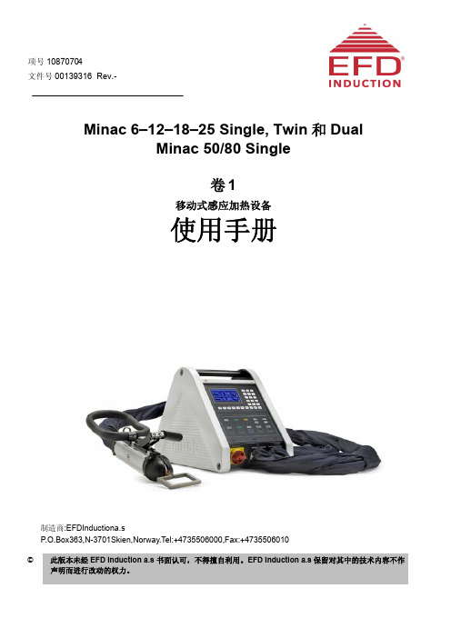
Minac 6–12–18–25 Single, Twin 和 Dual Minac 50/80 Single 卷1
பைடு நூலகம்移动式感应加热设备
使用手册
制造商:EFDInductiona.s P.O.Box363,N-3701Skien,Norway.Tel:+4735506000,Fax:+4735506010
© 此版本未经 EFD Induction a.s 书面认可,不得擅自利用。EFD Induction a.s 保留对其中的技术内容不作 声明而进行改动的权力。
缩写 FC = Frequency Converter 变频电源 HHT = Hand Held Transformer 手持变压器 HS = Heating Station 加热站 MMI = Man-Machine Interface 人机界面 OPN = Operating Panel 操作面板 ECU = External Control Unit 外部控制单元 CCM = Customer Communication Modules 客户通讯模块 CON = Converter Module 变流器模块 CAP = Output Capacitor 输出电容 ELR = Electronic Rack 电子架 MF = Medium Frequency 中频电源 HF = High Frequency 高频电源 EOR = Extended Operating Range扩展操作范围
©EFDInductiona.s.保留所有权利文件
00139316.Rev.-.2012-11-7
ii
7.4 线圈与工件距离 ........................
ACKU040 核心板用户手册说明书

KINTEX UltraScale开发平台用户手册ACKU040核心板2 / 24芯驿电子科技(上海)有限公司文档版本控制文档版本修改内容记录REV1.0创建文档目录文档版本控制 (2)一、ACKU040核心板 (4)(一)简介 (4)(二)FPGA芯片 (5)(三)DDR4 DRAM (5)(四)QSPI Flash (10)(五)时钟配置 (11)(六)LED灯 (12)(七)电源 (12)(八)结构图 (14)(九)连接器管脚定义 (14)3 / 244 / 24芯驿电子科技(上海)有限公司一、 ACKU040核心板(一) 简介ACKU040(核心板型号,下同)核心板,FPGA 芯片是基于XILINX 公司的XC7K325系列的XCKU040-2FFVA1156I 。
核心板使用了4片Micron 的1GB 的DDR4芯片MT40A512M16LY-062EIT,总的容量达4GB 。
另外核心板上也集成了2片128MBit 大小的QSPI FLASH ,用于启动存储配置和系统文件。
这款核心板的6个板对板连接器扩展出了359个IO ,其中BANK64和BANK65的104个IO 的电平是3.3V ,其它BANK 的IO 都是1.8V 。
另外核心板也扩展出了20对高速收发器GTH 接口。
对于需要大量IO 的用户,此核心板将是不错的选择。
而且IO连接部分,FPGA 芯片到接口之间走线做了等长和差分处理,并且核心板尺寸仅为80*60(mm ),对于二次开发来说,非常适合。
ACKU040核心板正面图5 / 24(二) FPGA 芯片核心板使用的是Xilinx 公司的KINTEX UltraSacale 芯片,型号为XCKU040-2FFVA1156I 。
速度等级为2,温度等级为工业级。
此型号为FFVA1156封装,1156个引脚,引脚间距为1.0mm 。
Xilinx KINTEX UltraSacale 的芯片命名规则如下图1-2-1所示:图1-2-1 KINTEX UltraSacale FPGA 型号命名规则定义其中FPGA 芯片XCKU040的主要参数如下所示:名称具体参数 逻辑单元Logic Cells 530,250 查找表(CLB LUTs) 242,400 触发器(CLB flip-flops) 484,800 Block RAM (Mb )大小 21.1 DSP 处理单元(DSP Slices )1,920 PCIe Gen3 x8 3GTH Transceiver20个,16.3Gb/s max速度等级 -2 温度等级工业级(三) DDR4 DRAM核心板上配有四片Micron(美光)的1GB 的DDR4芯片,型号为MT40A512M16LY-062EIT 。
EFD电源资料

Induction
Putting the smarter heat to smarter use
The Basics | The Benefits | The Technology | The Products | The Services | The Applications
SINAC PM/PH电源培训
The Basics | The Benefits | The Technology | The Products | The Services | The Applications
故障原因: 1)无法读取RAM内部数据(RAM或内部电池故障) 2)读/写RAM芯片不稳定 解决办法: 1)重启系统 2)RAM芯片插座故障或接触不良,重插 3)Saphyr故障,更换Saphyr
总 框 图
操作面板显示
The Basics | The Benefits | The Technology | The Products | The Services | The Applications
红灯:
F-max::频率过高 F-min:频率过低 U-max:输出电压过高 同时11号灯亮 解决方法: 检查proton模块 检查逆变电路 检查负载电路
The Basics | The Benefits | The Technology | The Products | The Services | The Applications
7号报警:输入主电压过压 8号报警:输入主电压过低 解决办法: 检查输入电网(400V+-10%)
9号报警:主电源相序错 解决办法: 调整相序 ps:电源准备好,但不能加 热
绿灯:+5V,+15V,-15V,+24V,+24VBT显示DC电源供电正常 绿灯mirco:显示芯片重启状态,on表示正常 绿灯electronique:显示程序工作状态。 On:1至6号无报警和芯片初始化正常。Off表示初始化不正常或出现报警。 Off:出现错误提示或“HEAT ON”一直处于on状态 PS:electronique绿亮on,Ready灯同时on lectronique绿灯off,Ready灯同时灭且Fault红灯on
EFD30-3F3-A315-S中文资料

Fig.2 EFD30 coil former; 12-pins.
5
0.05
27.5
1.3
0.15 0
MGC184
Winding data for EFD30 coil former with 12-pins
NUMBER OF SECTIONS
1
WINDING AREA (mm2)
52.3
1997 Nov 21
5
元器件交易网
Philips Components – a worldwide company
Australia: Philips Components Pty Ltd., NORTH RYDE, Tel. (02) 9805 4455, Fax. (02) 9805 4466.
CORE LOSS (W) at
GRADE
3C30 3C85 3C90 3F3 3F4
H = 250 A/m; f = 25 kHz; T = 100 °C
≥360 ≥320 ≥330 ≥315 ≥300
f = 25 kHz; Bˆ = 200 mT; T = 100 °C
≤0.50 ≤0.74 ≤0.50
Philips Components
EFD cores and accessories
Product specification
EFD30
CORES
Effective core parameters
SYMBOL
PARAMETER
Σ(I/A)
core factor (C1)
Ve Ie Ae Amin m
1997 Nov 21
2
元器件交易网
Philips Components
一文看懂超薄电源的pcb设计和制造窍门-干货分享

一文看懂超薄电源的pcb设计和制造窍门|干货分享
几年前市场上就开始有了宣称超薄电几年前市场上就开始有了宣称超薄电源产品,随着电子技术的飞速发展,人们源产品,随着电子技术的飞速发展,人们日常生活中所使用的电子产品越来越趋向日常生活中所使用的电子产品越来越趋向于轻薄、便携,最具代表性的要数笔记本于轻薄、便携,最具代表性的要数笔记本电脑了,其性能在不断增强的同时体积也电脑了,其性能在不断增强的同时体积也在不断缩小、日趋轻薄,其配套的电源适在不断缩小、日趋轻薄,其配套的电源适配器却依然笨重,当然轻薄的电源适配器配器却依然笨重,当然轻薄的电源适配器也有,但可算得上是屈指可数了,为什么也有,但可算得上是屈指可数了,为什么呢?
超薄电源的基本构成特点
■细长的电解电容
■超薄的磁芯
■高效率
高效率的一般方案
■BUCK PFC
■交错交错PFC
■LLC 谐振
■SR同步整流
其实,电源实现超薄最大困难不是在元件的选用上,也不是在方案的选型上,而是在工艺的设计上。
为什么这么说呢?
一个超薄的电源生产出来,其制造成本将会占整个电源的50%以上,甚至更以上,甚至更高…
下面将我个人在超薄电源工艺设计上的一些领悟分享给大家。
产品是几年前设计的一个全电压输入,输出65W的笔记本适配器。
电源保护系列C F-Frame和PD Frame ELC电流限制器安装说明说明书
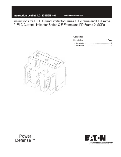
Contents Description Page 1.Introduction . . . . . . ... ..... . . . . ... ... ...22.Installation . . . . . . . . . . . . ....... ... .... . 2Instructions for LFD Current Limiter for Series C F-Frame and PD Frame 2. ELC Current Limiter for Series C F-Frame and PD Frame 2 MCPs. PowerDefense™2Instruction Leaflet IL012348EN H01Effective November 2020 Instructions for LFD Current Limiter for Series C F-Frame and PD Frame 2. ELC Current Limiter for Series C F-Frame and PD Frame 2 MCPs.EATON EQUIPMENT WHILE IT IS ENERGIZED. DEATH, SEVERE PERSONAL INJURY, OR SUBSTANTIAL PROPERTY DAMAGE CAN RESULT FROMCONTACT WITH ENERGIZED EQUIPMENT. ALWAYS VERIFY THAT NO VOLTAGE IS PRESENT BEFORE PROCEEDING WITH THE TASK AND ALWAYS FOLLOW GENERALLY ACCEPTED SAFETY PROCEDURES. EATON IS NOT LIABLE FOR THE MISAPPLICATION OR MISINSTALLATION OF ITS PRODUCTS. 2 . INSTALLATION IF REMOVING A CIRCUIT BREAKER INSTALLED IN AN ELECTRICAL SYSTEM, MAKE SURE THERCIRCUIT BREAKERS IS SWITCHED TO THE OFF POSITION AND THERE IS NO VOLTAGE PRESENT WHERE WORK IS TO BE PREFORMED. SPECIAL ATTENTION SHOULD BE PAID TO REVERSE FEED APPLICATIONS. THE VOLTAGES IN ENERGIZED EQUIPMENT CAN CAUSE DEATH OR SEVERS PERSONAL INJURY.Type ELCCurrent LimiterMax.Amps.Terminal wire connectors areUL listed for standard wire sizes as UL 486A or 486B Optional on special order for copper cable onlyStandard Aluminum Terminals Nonstandard Terminals (Steel)Wire RangeAWG(mm²)50100150#14-2#1-410#1-410(2.5-35)(50-95)(50-95)#14-2 ²(2.5-35)Wire Range AWG (mm²)The User is cautioned to observe all recommendations,warnings, and cautions relating to the safety of personnel and equipment as well as all general and local health and safety laws, codes, and procedures.The recommendations and information contained herein are based on Eaton experience and judgment, but should not be considered to be all-inclusive or covering every application or circumstance which may arise. If any questions arise, contact Eaton for further information or instructions.1. INTRODUCTION Current limter circuit breaker or current limiter/MCP combinations are designed for maximum protection and coordination, and should be applied in accordance with the current limiter nameplate. For example, the LFD3150R current limiter is for use with thermal-magnetic or electronic F-Frame or PD2, whereas the ELC3030R current limiter is only to be used with the 30A MCP.This noninterchangeability feature is made possible by combinations of molded projections and grooves and by several sizes of pierced and threaded terminals. Standard terminals are provided with the current limiter and are suitable for either copper or aluminum wire as shown in Table 1-1.For this publication, the term circuit breaker shall also include motor circuit protector.Table 1-1 Current Limiter Terminals Wire SizesNote : Before attempting to Install the current limiter, check that the catalog number is correct and that the rating of the accessory satisfies job requirements.A circuit breaker that is mounted in an electrical system must be removed to install the current limiter.2-1. Remove terminals from load end of circuit breaker.Note: During next step, molded projections of current limiter should fit inside the molded grooves in the circuit breaker.2-2. Position threaded terminals of current limiter under circuit breaker terminals.2-3. Secure current limiter to circuit breaker using the threee short screws and lockwashers (Table 2-1) provided in the packing envelope. Torque load screws (Table 2-1).2-4. Secure current limiter to mounting panel using long #8-32 screws provided in the packaging envelope.2-5. Connect cables to current limiter. Table 1-1 shows available connector types.Current LimiterAmperes Clamping Screw Torque value lb-in (N•m)25-70100-150 (also LFD3150R)#12-241/4-204060 to 80 4.52(6.78 to 9.4)˜²Eaton assumes no responsiblity for malfunctioning accessoriesinstalled by the customer.A circuit breaker that is mounted in an electrical system must be removedto install the current limiter.Table 2-1 Clamping Screw Torque Values and Usage.Instruction Leaflet IL012348EN H01 Instructions for LFD Current Limiter for Series C F-Frame and PD Frame 2.ELC Current Limiter for Series C F-Frame and PD Frame 2 MCPs.EatonElectrical Sector1000 Eaton BoulevardCleveland, OH 44122United States877-ETN-CARE(877-386-2273) © 2014 EatonAll Rights Reserved Printed in USA Publication No. IL012348EN Part No. IL012348ENH01Eaton is a registered trademark.All other trademarks are property of their respective owners.The instructions for installation, testing, maintenance, or repairherein are provided for the use of the product in general commercialapplications and may not be appropriate for use in nuclear applica-tions. Additional instructions may be available upon specific requestto replace, amend, or supplement these instructions to qualify themfor use with the product in safety-related applications in a nuclearfacility.This Instruction Booklet is published solely for information purposesand should not be considered all-inclusive. If further information isrequired, you should consult an authorized Eaton sales representa-tive.The sale of the product shown in this literature is subject to theterms and conditions outlined in appropriate Eaton selling policiesor other contractual agreement between the parties. This literatureis not intended to and does not enlarge or add to any such contract.The sole source governing the rights and remedies of any purchaserof this equipment is the contract between the purchaser and Eaton.NO WARRANTIES, EXPRESSED OR IMPLIED, INCLUDINGWARRANTIES OF FITNESS FOR A PARTICULAR PURPOSE ORMERCHANTABILITY, OR WARRANTIES ARISING FROM COURSEOF DEALING OR USAGE OF TRADE, ARE MADE REGARDINGTHE INFORMATION, RECOMMENDATIONS, AND DESCRIPTIONSCONTAINED HEREIN.In no event will Eaton be responsible to the purchaser or user incontract, in tort (including negligence), strict liability or otherwisefor any special, indirect, incidental or consequential damage or losswhatsoever, including but not limited to damage or loss of use ofequipment, plant or power system, cost of capital, loss of power,additional expenses in the use of existing power facilities, or claimsagainst the purchaser or user by its customers resulting from theuse of the information, recommendations and description containedherein.Effective November 2020。
- 1、下载文档前请自行甄别文档内容的完整性,平台不提供额外的编辑、内容补充、找答案等附加服务。
- 2、"仅部分预览"的文档,不可在线预览部分如存在完整性等问题,可反馈申请退款(可完整预览的文档不适用该条件!)。
- 3、如文档侵犯您的权益,请联系客服反馈,我们会尽快为您处理(人工客服工作时间:9:00-18:30)。
CIES 板
(逆变驱动卡)
CIES 板- 功能
晶体管门极驱动 驱动过流检测 外部信号接口
再休息一会儿。。。
其他电子卡
ITFS – 流量传感器接口板
新流量传感器接口板. 输出线从 MECC 至 MCCC
其他电子卡
DCCM – DC 电流检测
电流检测信号给 MCCC
连接到 VTCC 板
蓝色的 LEM 检测电流 红色的压敏电阻当发生过压时会产生一个短路保护. (有时候可以去掉)
安装在MECC(母板)卡背面 打开左边盖板(面对操作面板方向), 拆下CIES板卡 拿开两根扁平线 轻松的就可拿下 MBAC 卡,不要用蛮力。
MCCC (微处理器板)
MCCC – 功能
控制显示
设定 (相关参数如何显示) 数值 (棒图及数值等) 功能按钮的操作 报警信息
相关信号给外部插口
维修/维护
启动: 供电: 良好的主电路连接. 水: 4 至6 压力,管径满足流量要求. HHT: 感应器底座以及HHT接口整洁平整, 保证良好的导电性能.
维修/维护
维护: 定期检查水质,水质脏会导致流量传感器 检测错误.
这是一个常见问题
维护 – 冷却水
金属颗粒粘附在磁头 上面
老版本的 Minac or Sinac常见该故障
MINAC电子板卡的位置 (1)
Minac右侧板打开:
SMPS
POWS
2x FIPX
MCCC
MINAC电子板卡的位置(2)
Minac左侧:
CIES
MBAC:取下 CIES 板可见
Position of cards in SINAC
MCCC 2x FIPX POWS SMPS MBAC 2x CIES
Minac/ Sinac 25/40 Minac/Sinac 50/80
其他电子卡
FVCM - 电压电流检测以及滤波
电压以及电流检测 和 VTCC /DCCM两者结合起同 Minac/Sinac 12/18 Minac/Sinac 1825
(Converter module 1013 S and T)
Common Alarm Capacitive Alarm 134 Inductive Alarm 133 External Alarm
FIPX – 维修检查
根据指示灯进行诊断 (结合报警显示) 只能更换 – 必须提供正确的版本号以及 序列号 不要试图进行任何调整 (除非EFD服务人 员要求你这么做)
FIPX 电子卡
FIPX指示灯信息
FIPX CARD
KEY Invertor AC Current regulation Power Regulation Auxilliary Regulation Maximum Regulation Invertor OFF Limit active Invertor ON Frequency High Alarm 150 Frequency Low Alarm 149 AC overcurrent alarm 132 Abbreviation lac-reg Pow-reg Aux-reg Max Reg Off Lim-act On F-High F-Low Over-Current LED LED Abbreviation Red-inv Inv-lim Uc1-lim DtC-lim Uc2-lim Phi-lim Com-al Cap Ind Ext KEY Invertor Limit Duty cycle active
介绍 – 电子板卡
电子板卡适用于:
MINAC’s (移动单元) SINAC’s (固定单元)
MINAC
MINAC 18/25
SINAC 18/25
主要电子板卡:
SMPS 开关电源板 POWS 电源板 MECC 母板
FIPX 频率电流功 率调整板 MBAC 母板扩展 板 MCCC 主控制板
Minac/ Sinac 25/40 Minac/Sinac 50/80
其他电子卡
VTCC – 双接口电压电流检测板
电压检测 输出信号至 MBAC 以及MCCC 信号来源于 DCCM 板
3 个25KΩ电阻(安装在DCCM板后面的冷却板上)串联起来连接到– 电阻损坏
会导致”DC 电压过低”, ”DC 电压过高” 报警
MINAC外部接口
Minac外部接口
Minac外部接口 X-9 (x-9.1 twin version)
输出信号:
输入信号:
电源准备 正在加热输出 功率反馈信号 电源故障
功率设定值 加热信号 复位信号 外部停止信号 急停信号
SINAC外部接口 X 10 (X 10.1 twin version)
MBAC 板
MBAC –功能
母板扩展板
检测DC 电流 以及DC 电压 Outputs 0-10V for each DC value
FIPX/MCCC)
(至
接地检测 (1 & 2工位) DC 过流以及DC 过压检测 数字量信号输入输出到MCCC
MBAC 板 (位置/更换)
MECC – 功能
”电子卡安装母板” 的主要功能: 其它电路板的信号的接口交汇功能.
MBAC 板安装在MECC板的背面。
休息10分钟........
FIPX板
FIPX板- 功能
控制切换开关信号 设定工作参数
频率,电流以及功率的调节和控制 报警值设定 限制相应的输出
FIPX 块图
备件推荐
推荐的备件清单: 1 pcs HHT (4-8周的交货期) 1 pcs Cies卡 1 pcs Mbac卡 2 pcs IGBT晶体管 1 pcs 备用感应器 1 pcs 漏水检测传感器
谢谢您的参与
您已经完成了这项培训....
还有什么问题吗?
POWS 板 – 原理图
POWS 板 – 功能
输入: 从SMPS 电子卡而来
输出: + 5vDC +12vDC - 12vDC + 24vDC
4 个绿色LED灯分别指示四种电压的状态
MECC (电子卡安装母版)
MBAC 板连接在这里
MECC (layout-1)
MECC (layout-2)
SMPS (Switch Mode Power Supply开关电源板)
Smps: 原理图
SMPS主要功能
输入 = 120-250VAC
输出 = 7Vdc 至Pows板 +/- 15VDC 至 Pows板 24VAC to Pows板 24VAC to 驱动板
POWS 板 – (Power Supply card电源供应板)
