微水利发电
微型水力发电厂技术方案说明书
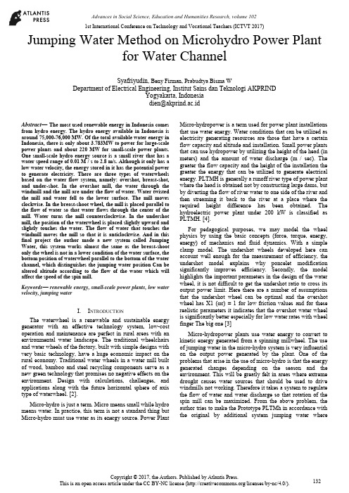
Jumping Water Method on Microhydro Power Plantfor Water ChannelSyafriyudin, Beny Firman, Prabudtya Bisma WDepartment of Electrical Engineering, Institut Sains dan Teknologi AKPRINDYogyakarta, Indonesia***************.idAbstract—The most used renewable energy in Indonesia comes from hydro energy. The hydro energy available in Indonesia is around 75,000-76,000 MW. Of the total available water energy in Indonesia, there is only about 3.783MW to power for large-scale power plants and about 220 MW for small-scale power plants. One small-scale hydro energy source is a small river that has a water speed range of 0.01 M / s to 2.8 m/s. Although it only has a low water velocity, the energy stored in it has the potential power to generate electricity. There are three types of waterwheels based on the water flow system, namely: overshot, breast-shot, and under-shot. In the overshot mill, the water through the windmill and the mill are under the flow of water. Water twisted the mill and water fell to the lower surface. The mill moves clockwise. In the breast-shoot wheel, the mill is placed parallel to the flow of water so that water flows through the center of the mill. Water turns the mill counterclockwise. In the undershot mill, the position of the waterwheel is placed slightly upward and slightly touches the water. The flow of water that touches the windmill moves the mill so that it is anticlockwise. And in this final project the author made a new system called Jumping Water, this system works almost the same as the breast-shoot only the wheel is not in a lower condition of the water surface, the bottom position of waterwheel parallel to the bottom of the water channel, which distinguishes the jumping water position Can be altered altitude according to the flow of the water which will affect the speed of the spin mill.Keywords— renewable energy, small-scale power plants, low water velocity, jumping waterI.I NTRODUCTIONThe waterwheel is a renewable and sustainable energy generator with an effective technology system, low-cost operation and maintenance are perfect in rural areas with an environmental water landscape. The traditional wheelchairs and water wheels of the factory, built with simple designs with very basic technology, have a huge economic impact on the rural economy. Traditional water wheels in a water mill built of wood, bamboo and steel recycling components serve as a new green technology that promises no negative effects on the environment. Design with calculations, challenges, and applications along with the future horizontal sphere of axis type of waterwheel. [2].Micro-hydro is just a term. Micro means small while hydro means water. In practice, this term is not a standard thing but Micro-hydro must use water as its energy source. Power Plant Micro-hydropower is a term used for power plant installations that use water energy. Water conditions that can be utilized as electricity generating resources are those that have a certain flow capacity and altitude and installation. Small power plants that can use hydropower by utilizing the height of the head (in meters) and the amount of water discharge (m / sec). The greater the flow capacity and the height of the installation the greater the energy that can be utilized to generate electrical energy. PLTMH is generally a runoff river type of power plant where the head is obtained not by constructing large dams, but by diverting the flow of river water to one side of the river and then streaming it back to the river at a place where the required height difference has been obtained. The hydroelectric power plant under 200 kW is classified as PLTMH. [4].For pedagogical purposes, we may model the wheel physics by using the basic concepts (force, torque, energy, energy) of mechanics and fluid dynamics. With a simple clamp model. The undershot wheels developed here can account well enough for the measurement of efficiency, the undershot model explains why poncelet modification significantly improves efficiency. Secondly, the model highlights the important parameters in the design of the water wheel, it is not difficult to get the undershot ratio to cross its output power limit. Here there are a number of assumptions that the undershot wheel can be optimal and the overshot wheel has X1 (ωr) = 1 for low friction values and for these realistic parameters it indicates that the overshot water wheel is significantly better especially for low water rates with wheel finger The big one [3]Micro-hydropower plants use water energy to convert to kinetic energy generated from a spinning millwheel. The use of jumping water in the micro-hydro system is very influential on the output power generated by the plant. One of the problems that arise in the use of micro-hydro is that the energy generated changes depending on the season and the environment. This will be greatly felt in areas where extreme drought causes water sources that should be used to drive windmills not working. Therefore it takes a system to regulate the flow of water and water discharge so that rotation of the spin mill can be maximized. From the above problem, the author tries to make the Prototype PLTMh in accordance with the original by additional system jumping water where1st International Conference on Technology and Vocational Teachers (ICTVT 2017)jumping water will be given auto or manual system to raise or lower the height of the angle jumping water to adjust the intensity of water flow, the method used is to conduct measurement experiments Of the prototype that has been made.1.Micro hydro Power PlantWater WheelBecause the overshot efficiency remains high for various streams, it is suitable in places where water sources vary. However, when the speed and rotation velocity exceeds a certain value, the volumetric loss determines the waste of water, resulting in a decrease in efficiency and possible damage to the wheel. Each cell should only be charged up to 30-50% of its volume, to reduce volumetric loss during rotation. The tube should be shaped so that the water jet can enter each cell at a natural falling angle, with the gap of each cell slightly wider than the jet, to allow air release. However, in the overshot wheels being studied, it is the potential energy of water that is the main torque for the wheel. The shape of the cell must retain water in the cell to the lowest position, when it eventually empties quickly. Wheel diameter is determined by high difference, while relative speed is not a simple parameter to be optimized. When the wheel spins at a very low speed. When the cell moves too fast, only a small amount of water can enter each cell, due to volumetric loss. From the experimental results, we can claim that for the steering wheel tangent speed is lower than 75-80% water velocity, high efficiency and fairly constant with wheel speed, In our case study, two different rotation speeds are u Identified: runaway speed ωr,In which the output power tends to be zero (ω = 4.2 ÷ 4.3 rad / s) and critical velocity ωcr, where the output power begins to decrease bruquely (ωcr = 2.7 Rad / s). For higher efficiency than at 80% for various streams [5]One of the new renewable energy types is small scale hydro power or often called microhydro or PLTMh. Microhydro obtains energy from a water stream having a certain high difference and water flow velocity, the energy generated by the physical model of waterwheel is a renewable energy can be measured using a digital torque tester that is connected to the axis of the model of the mill. High speed of rotation not necessarily have great energy because if given a little load will greatly affect the speed of rotation of the purpose of this research is to develop technology, materials, mechanical components, electronic components and design of energy resources system, so have a strategic impact to Technological developments and applicable in society, the measurement of a waterwheel rotation using a tachometer yields a permenite spin value (RPM) that affects the energy value generated from the wheel. The model of the mill used is undershot. From the result of research, it is known that the highest speed of roundwheel in H1h1 (1 cm high base of the windmill on the bottom of the channel and 1 cm of water gate downstream) is 13,76 RPM, the highest energy obtained by using torque meter at H1h1 is 78, 30 cNm or 0.0002175 watthour [7].In particular, breast-shot waterwheels are used in locations with high flow rates, such as irrigation canals and grinding, with a height generally less than 4 m. In this paper, experimental results are reported to illustrate how rainwater rotation efficiency under different hydraulic and geometric configurations. Two different flow configurations are investigated: the first has a water gate on the upstream of the wheel (the opening is adjustable), the second is a dam. Two dams of different heights were installed on the upstream of the wheel and investigated. The maximum efficiency for opening of flood gates> 0.075 m is fairly constant in the range between 0.05 <Q <0.08 m3 / s for α> 0.10 m, while efficiency with the dam increases, indicating that the wheel is able to exploit larger volumes The dam water improves the efficiency of the wheels at very low discharge (Q <0.03 m3/s), and gives a significant effect on high power inputs ). normalized tangential normal speeds are included in the range for cases with gate gates and weirs, respectively. The optimal fill rate is usually included in the range of 0.3 ÷ 0.5. This range can be regarded as the optimal operating conditions for a breath shot similar wheel. Therefore, both the correct design of the elevation of the dam and the opening of the sluice can be considered as an appropriate method to optimize working conditions and efficiency of the breath shot wheel. [6]Fig. 1. Overshot waterwheel type2.Overshot systemAn overshot waterwheel works when the flowing water falls into the upper part of the blade and due to the gravity of the water wheel rotates. The overshot water mill is the most widely used water mill compared to other types of waterwheelsAdvantages• High efficiency level can reach 85%.• Does not require heavy flow.• Simple construction.• Easy to maintain.• Simple technology is easy to implement in isolated areas. Loss• Since the water flow comes from above it is usually a reservoir of water or a water dam, requiring more investment.• Not applicable for high rotary machines.• Requires more space for placement.• The power generated is relatively smallFig. 2. Undershot waterwheel type3.Undershot systemUndershot water mill works when running water strikes the wall at the bottom of the waterwheel. Undershot water mill rely solely on the water capacity (Q) without having additional advantages of head or different water levels. This type of waterwheel is suitable for installation in shallow, flat waters. This type of waterwheel is also called the "Vitruvian". Where the water flow is opposite to the direction of the blade that turns the mill.Advantages of Undershot type• The construction is simpler• More economical• Easy to moveLoss• Small efficiency• The resulting power is relatively smallFig. 3. Breathshot waterwheel type4.Breastshot systemBreastshot water wheel is a blend of overshot and undershot types seen from the energy it receives. The fall distance does not exceed the diameter of the mill, the direction of the water flow that drives the waterwheel around the shaft axis of the waterwheel. This type of water mill improves the performance of an under shot water mill [1].Advantages• This type is more efficient than under shot type• Compared to the overshot type the height of the fall is shorter• Applicable to flat-flow water sources.Loss• The angles of this type are not flat like undershot type (more complicated)• Required dams on the flow of flat flows• Efficiency is smaller than the overshot typeThe microhydro prototype is designed using a waterwheel with a triangle blade type model to facilitate the wheel in accepting the flow of water from jumping water. As in FIG. 2, there are 3 pieces which are made to form an arch so that water is not immediately wasted but can be accommodated temporarily on the outermost piece of the pin blade which functions in order to increase the resulting torque value.Fig. 4. WaterwheelII.DISCUSSION1.Jumping WaterThis microhydro prototype jumping water is very influential on the rotation of the mill, to know the acceleration of rotation speed of the mill, the writer takes into account the angle of jumping water height, by slipping the acrylic slabIn a drawer already mounted on a drain. The test is done in different angles as in figure (3). [8]Fig. 5. Jumping water modelPlanning system on making micro-hydro prototype with jumping water one of the measurement of angle generated jumping waterThe first step is to know the calculation of the angle that will result in the height of Jumping water. [8]Fig. 6. Right triangleIn figure (4) can be ascertained Y at altitude, Z at the slope, and X at P1 or the length of the angle calculation. The formula for finding the height of jumping water and X on P1 or the length of the angle calculation;To search longX = Z Cos θX (P1) = 30 cos 10o= 29.5 cmTo search highY = Z Sin θY = 30 Sin 10o= 5.2 cmFrom the results of the calculation of the above angles can be generated as recorded in the table below, the authors conducted trials using 5 experiments, ranging from 10o to 50o.[8]T ABEL 1. CALCULATION RESULT FOR JUMPING WATERWe can see the results of the calculations produced with 5 angle experiments from 10o to 50o, for X (P1) to know the position between the windmill with Jumping water, and for (y) to find the magnitude of the angle Jumping water.III.R ESULTSMeasurement results on the design of jumping water on microhydro prototype will also be made several measurements, among others;Measurement of the length and angle of Water FallIn this measurement when the data is taken and the test of this device the position of the kinci is removed or not using the mill, the water still runs through Jumping Water. This measurement uses beerapa tools such as ruler and bow degree and obtained the results of data as in the table below.After the results obtained from the data retrieval 5 times the experiment every angle it can be searched average water fall angle and high fall water.T ABEL 1.A VERAGE NUMBER OF DISTANCE MEASUREMENTS AND FALLINGANGLE OF WATERFig. 7. Graph of angle falling water measurementsA. Measurement of spindle blade distance with jumping waterThis measurement is carried out to determine the distance between the blade of the windmill and the Jumping water which will affect the turn of the mill, as shown in Figure (10).Fig. 8 High measurement graph of falling water and distance falling water against angle jumping waterFig. 9. Measuring the distance of the turbine blade with Jumping WaterFrom the above data retrieving result, the turn of the mill with the ratio of the distance between the blade of the windmill with Jumping water can be inferred or in the average according to the angle/height of jumping water, which is inputted into table (4).T ABLE 3M EASUREMENTS WITHOUT J UMPING W ATERT ABLE 4M EASUREMENTS WITH J UMPING W ATERFrom the average comparison of the distance between the spindle blades with Jumping Water above shows that the revolution of the mill turns can increase and also the power generated will be greater in accordance with the height of Jumping Water and also the distance between the wind blade and Jumping Water.Figure.10. rotation of a millwheel from measuring the distance between a water wheel against a jumping waterIV.C ONCLUSIONBased on the result of making, assembling and application of jumping water at this PLTMH directly with this writer take the conclusion based on data collecting either by performance test, tool design and system work of jumping water at PLTMH. Here are the conclusions that can be taken:1.The round by using jumping water from 10o-50o is veryinfluential on the rotation of the mill, the higher the angle jumping water the faster the round produced by the wheel.2.High jumping water effect on the distance and angle offalling water (experiments without a mill) the higher the angle then the distance falling water and the falling angle of water is also getting bigger3.The distance between the water wheel against thejumping water is very influential on the waterwheel spin, the farther the distance then the waterwheel turns down.V.SUGGESTIONSuggestions for further development is the use of jumping water on this micro-hydro prototype by adding automatic drive system in jumping water in order to raise and lower jumping water automatically in order to facilitate during theoperation of this prototype in the laboratory. Acknowledgments to Kemenristek Dikti special DRPM for the grant aid of research given so this research can be done well.REFERENCES[1]BACH C. v., 1886, Die Wasserräder (The water wheels, in German),Konrad Wittwer Verlag,Stuttgart.[2]Denny, M, 2004., The Eficiency of overshot and undershot waterwheels.European Journal of Phisics 25(2): 193-202[3]Felix Mwema, Gheewala Shabbir H. 2012 Environmental assessment ofelectricity production in Tanzania. Energy for Sustainable Development December 2012[4]Praful Yelguntwar, Pranay Bhange, Yogesh Lilhare, Ankit Bahadure,2014, Design, Fabrication & Testing of a Waterwhell for power generation in a n open channel flow, International Journal of Resach inEngineering and Advanced Technology (IJERAT), volume 2 issue 1, feb-mar 2014[5]Quaranta E, Ravelli R. 2015,. Out put power and power lossesestimatiom for an overshot water wheel, journal renewable energy elsevior[6]Quaranta E, Ravelli R. 2016., Optimization of Berastshot water wheelsperformance using different inflow configuration, journal renewable energy elsevior[7]Rinaldi, 2015, Model Fisik Kincir air sebagai pembangkit listrik, annualcivil Engineering seminar pekanbaru 2015. ISBN 978-979-792-636-6. [8]Syafriyudin, 2016, “Peningkatan kapasitas Pembangkit Lis trik TenagaMikrohidro di desa wisata Kebon Agung kecamatan Imogiri, Kabupaten Bantul Yogyakarta”. Prose ding Seminar Nasional Pendidikan Tinggi Vokasi Indonesia. Universitas Haluoleo. Kendari.8 Maret 2016.。
小型水力发电机
斜击式小型水力发电机斜击式小型水力发电机5KW,需要水头为15-50米左右,水流量为:0.047-0.014立方米/秒。
可以选配永磁单相发电机和励磁三相发电机。
斜击式小型水力发电机5KW配永磁单相发电机重量约为:150kg。
一、小型水力发电站简介:建微水电站是在有一定水头落差的地方,通过筑坝拦集小溪流水,通过管道等将水引入水力发电机组,推动水轮带动电机发电,然后通过输电线供给用电户。
二、斜击式水力发电原理:在有水落差比较高的地方,用水管将水从高处引往低处,由于水位差高,水产生比较高的压力,在高压力的作用下,水的流速非常快。
在水轮机处装有圆形的小喷口,高压高速的水流喷射到斗状的叶片上带动水轮机高速旋转,从而带动发电机发电。
在这里主要就是利用水的高压高速能量,因此,高落差非常重要。
水位差,或者说水流落差,我们简称为水头。
三、功率计算:水流量和水头就可以决定安装发电机组的功率。
水流量一般是指一秒钟内流出的水的体积。
以立方米/秒为单位。
理想理论上安装功率的计算公式为:水头(m)×流量(m3/s)×9.8=功率(KW)。
实际上机组的效率并不是100%,因此要把机组的效率算上。
一般水头我们以H来表示,流量以Q来表示,机组效率为η来表示,一般η取0.7左右。
g表示重力加速度,功率以P来表示,那么安装功率的计算公式为:P = HQηg例如:水流量为0.02m3/s,水头为10米高,那么可以安装的功率为:0.02×10×9.8×0.7 =1.372(KW),即实际可以安装功率为:1千瓦左右。
流量比较难测量一般以估算法来测。
首先估算出水的流速,然后再估算出水流的横截面积大小,即可算出水流量大小。
流量(m3) Q = Sv 其中S为横段面积(m2),v为流速(m/s)①、首先测量得水沟的横截面积S,比如可量得水沟的宽、高粗略算出横截面积S,如要测得更准确,可对水沟的横截面积进行分割细分测得各小块面积,然后再相加得出总面积。
水力发电机介绍及应用
水力发电机介绍及应用1. 介绍水力发电机是一种利用水流通过涡轮旋转产生机械能,驱动发电机发电的设备。
它是一种清洁、可再生的能源发电方式,被广泛应用于全球各地。
2. 工作原理水力发电机的工作原理基于水的重力势能转化为机械能,然后再转化为电能。
主要包括以下几个步骤:1. 水流被引导到涡轮上,涡轮叶片受水流的冲击旋转。
2. 涡轮旋转带动发电机转子转速增加。
3. 发电机通过磁场和线圈的相互作用产生电流。
4. 电流经过变压器升高电压,最终输送到电网中。
3. 应用水力发电机在各个领域都有广泛的应用。
以下是一些常见的应用领域:1. 水电站:水力发电机是水电站的核心设备,通过将水流引导到涡轮上,将水的能量转化为电能,为电网供电。
2. 农村电化:在水资源丰富的农村地区,可以利用小型水力发电机为农户提供电力,实现农村电网的建设。
3. 乡村旅游:在风景秀丽的乡村旅游景区,可以利用小型水力发电机发展微型水电站,为景区提供绿色电力。
4. 农业灌溉:利用水力发电机为农业灌溉系统提供能源,减少对传统能源的依赖,节约能源成本。
4. 环保优势水力发电机作为一种清洁能源发电方式,具有以下环保优势:1. 无污染:水力发电不产生废气、废水和固体废物,对环境不会造成污染。
2. 低碳排放:水力发电不燃烧燃料,几乎不产生二氧化碳等温室气体的排放。
3. 可再生:水力发电依赖于水循环,水资源可再生,不会造成能源枯竭。
5. 潜力和发展趋势由于水力发电机的环保性和可再生性,其在未来的能源发展中具有巨大的潜力和发展空间。
随着技术的不断进步,水力发电机的效率和可靠性将不断提高,更加适应各种地理条件的利用。
6. 结论水力发电机作为一种清洁、可再生的能源发电设备,在全球范围内得到广泛应用。
它不仅具有环保优势,而且潜力巨大,有望在未来的能源发展中发挥更重要的作用。
2024年微型水力发电机市场前景分析
2024年微型水力发电机市场前景分析摘要本文对微型水力发电机市场前景进行了深入分析,通过对市场趋势、竞争对手、发展机会等方面的研究,得出了市场前景持续增长的结论。
引言随着能源需求的增加以及环境问题的日益严重,可再生能源逐渐成为人们关注的焦点之一。
其中,微型水力发电机作为一种清洁能源发电设备,具有体积小、效率高、适用性广等优点,受到了越来越多的关注。
本文将围绕微型水力发电机市场前景进行深入分析,以期为相关行业的发展提供参考和借鉴。
市场趋势分析微型水力发电机市场在过去几年内呈现出较快的增长势头。
以下是该市场的主要趋势:1.政策支持:许多国家纷纷出台了鼓励发展可再生能源的政策措施,为微型水力发电机市场提供了良好的发展环境。
政府补贴和税收减免等政策措施吸引了越来越多的企业和个人投资于微型水力发电机项目中。
2.技术创新:随着科技进步和工艺改进,微型水力发电机的效率和可靠性得到了显著提高。
新型材料的应用、智能化控制系统的推出等,使得微型水力发电机具备更好的适应性和竞争力。
竞争对手分析目前,微型水力发电机市场存在着激烈的竞争。
以下是主要竞争对手的分析:1.企业A:该企业是市场上的领导者,拥有先进的技术和完善的销售网络。
他们的产品质量稳定可靠,市场占有率较高。
2.企业B:这是一个新兴的企业,他们注重创新,不断推出新产品以满足市场需求。
虽然市场份额较低,但有潜力与领导者竞争。
发展机会分析微型水力发电机市场具有广阔的发展前景,以下是市场中存在的主要机会:1.新兴市场的开拓:随着各国对可再生能源的重视程度提高,尤其是发展中国家的市场潜力巨大。
微型水力发电机可以满足这些地区的能源需求,具有良好的发展前景。
2.项目投资的增加:多个国家对微型水力发电机项目进行投资,以满足清洁能源发电的需求。
这将为微型水力发电机市场创造更多的商机和机会。
结论从市场趋势、竞争对手和发展机会的分析中可以看出,微型水力发电机市场具有持续增长的前景。
水力发电的原理与种类

水力发电的原理与种类水力发电是利用水能转化为机械能然后转化为电能的发电方式。
其基本原理是通过水流的冲击力作用于水轮叶片,驱动水轮转动,进而带动发电机转子发电。
1.水头发电:该种类发电利用长江、长江枯水期、辽河、珠江等大型河流及其支流水头较大的地段,建设大坝,形成水库,通过调节蓄水、放水流量,使水流带动涡轮机发电。
水头发电具有水头高、水流量大的特点,发电效率高,是最常见的水力发电方式。
2.引力发电:引力发电是通过静态水压力(流体静压力),通过引导水流,使水流加速并带动涡轮机发电。
引力发电与水头发电的区别在于,流体静压力驱动涡轮机而非水流动力。
该种类水力发电适用于比较平缓的河流或低比能河流。
3.潮汐发电:潮汐发电是利用潮汐引起的水位变化差异来发电。
在适合的地理条件下,可利用潮汐水流巨大的动能,带动涡轮机发电。
潮汐发电的优点是稳定可靠,但规模大、适用范围窄,目前仍处于发展初期。
4.海洋能发电:海洋能发电是指利用海洋资源,包括波浪能、潮汐能、海流能和温差能等进行发电。
其中,波浪能是利用波浪的起伏运动带动发电机发电;潮汐能是利用潮汐引起的水位变化差异驱动发电机发电;海流能是利用海洋中的水流运动带动发电机发电;温差能是利用海洋冷热水的温差差异产生热膨胀和热收缩,从而驱动发电机发电。
海洋能发电具有较大的发电潜力和稳定性,但技术上仍面临一定的挑战。
水力发电具有很多优点,如可再生、清洁、无污染、发电效率高等。
然而,水力发电也存在一定的局限性,如需要大规模的水库和大坝、生态环境受到影响、建设和运维成本较高等问题。
因此,在选择水力发电方式时需要综合考虑各方面的因素。
随着技术的不断进步,水力发电未来的发展前景仍然广阔,将继续为人类提供可持续、清洁的能源。
“农村新能源开发与节能关键技术研究”项目——课题三/子课题:微型水力发电关键技术研究与技术集成

开发 利用和 运行 管理பைடு நூலகம்带来 方便 。 1 、软件 功能
可 再生 能 源
本 软 件 采 用 标 准 化 设 计 ,技 术 方 案 可 靠 ,具 有 良 好 的 可 扩 展 性
性 ,利 用动态经 济计算 方法 .确定 经济流速 取值 范围 。 1 ,管材 的水力性 能参数确 定
使 用专业 性较 强 的管理技 能成 为可 能 。因此 .本 软件 采用标 准化 的
设 计 .对 技 术 性 很 强 的 规 划 设 计 通 过 复 杂 的 软 件 程 序 有 效 地 转 化
为人 性化 的操 作界 面 ,用户 只需根 据 工程 实际数 据进 行简单 的参 数
选 择 和 输 入 通 过 程 序 运 行 来 实 现 规 划 、 设 计 和 评 价 为 微 水 电 的
还 有 9 4 0w,占 7 %。 6 6k 7
微型 水 力发 电 ( 称微 水电 )是指 利 用 电力负 荷附近 的微 小水 简
能 资源发 电 、高 网独 立运 行 、无 需 变电 、直 接 向用户 供 电或者 与地
方 农 网 并 网 运 行 的 水 力 发 电 系 统 。 与 大 中型 水 力 发 电 不 同 ,微 水 电
不造 成 自然生态 改 变和环 境污 染等 负面 影响 。 微 水 电 的 电 能 转 化 率 至 少 可 达 5 % 远 远 高 于 其 它 可 再 生 能 源 0 ( 阳能约 2 %J 太 0 ,单 位 千 瓦 造 价 远 远 低 于 风 能 和 太 阳能 加 之 维 护 管 理 便 捷 ,容 易 实 现 用 户 自筹 、 自 建 、 白管 、 自 用 ,优 势 明 显 。
微水 能资源 范 围分 布很广 包 括小 溪 河湾 、泉 水 、高 山湖泊 、
2023年微型水力发电机行业市场前景分析

2023年微型水力发电机行业市场前景分析随着环保意识的增强以及能源需求的不断增加,微型水力发电机行业市场前景正处于迅速发展阶段。
在未来数年内,微型水力发电机行业将迎来更加广阔的市场机遇。
本文将从行业概述、市场规模、应用方向、发展趋势等多个方面进行分析。
一、行业概述微型水力发电机是指安装在水流中或管道中的小型水力发电机,一般功率在5KW以下。
微型水力发电机不仅在一些偏远地区代替传统的机械发电,增加了当地的供电能力,而且还可以在城市生活中低碳环保的绿色能源供应中扮演重要角色。
二、市场规模据相关机构预测,2018年-2023年全球微型水力发电机市场规模年均增长率将达16.1%,2023年市场规模预计将达到18亿美元左右。
其中,亚太地区以其巨大的市场规模和强劲的经济增长势头成为微型水力发电机市场的最大消费市场。
三、应用方向在应用方向上,微型水力发电机因其特色能够被广泛应用于各种领域。
其中包括:1、自然条件不太适宜大规模水电站建设的偏远地区,如山区、高原地区等;2、废水处理场、污水处理厂等既能净化水源,又能利用水流发电的水资源;3、地源热泵供电,即以河水作为地源热泵的冷热源,利用水流发电;4、锻压机械配合,利用水流动力驱动锻、压机械工作。
四、发展趋势1、技术逐步成熟:随着微型水力发电机技术的逐步成熟,其性能逐渐得到提升,从而推动了市场发展。
2、政策的支持:各国政府出台的环保政策支持以及对可再生能源的鼓励政策,都为微型水力发电机市场提供了新的机遇。
3、大型水电站的成本增加,推动微型水力发电机市场发展:不可否认,随着电力需求的增长,大型水电站已经成为常规的选择。
但是,大型水电站建设所需的巨额资金、险资程序的漫长、环保压力的不断增加以及河道改道所带来的环境负面影响等因素也限制了大型水电站的建设。
而微型水力发电机,由于成本相较大型水电站更为可控,因此也吸引了投资者的关注。
总之,未来微型水力发电机行业将保持迅猛发展势头,行业市场前景十分广阔。
GB17523-1998 微型水力发电设备试验方法
的单相 20 3 V和三相 40 0 V微水电整机产品的原型机检查试验、 型式试验和质量监督抽检试验等。
机械调速式 0 1 k 及以下微水电产品可参照执行。 W
引用标准
下列标准所包含的条文, 通过在本标准中弓用而构成为本标准的条文。本标准出版时, ! 所示版本均 为有效。所有标准都会被修订, 使用本标准的各方应探讨使用下列标准最新版本的可能性。
GB ' 15 3 1 9 / 7 2- 98 r
试验时, 调节进水阀门并改变负载, 使水力发电设备保持在额定电压下, 待系统运行稳定后, 再同时 读取水头、 流量、 输出电功率值, 并按式()式() 4 、 5计算水力发电设备的总输入功率和效率。
N = 9 8 QH . 1
(4)
,)N 1 ( 一 x0 % P 0
按G / 75 97 5-18 中第62 BT . 条规定的要求进行。
试验前应先测定绕组的绝缘电阻。在冷状态下测得的绝缘电阻, 按绕组的额定电压计算应不低于
1 k 如需进行温升试验时, Mn/V。 则本项试验应在温升试验后进行。 试验应在电机静止状态下进行。 试 验电压的频率为 5(0Hz波形应接近正弦波, 06) , 试验电压的有效值见表 2 0 表 2 试验电压的有效值
o 二 一 二 一- ( + t)+ t 一 t f 一 ;~ x , , o
八z
R。一 R, _ _
一 一 一
式中: f 发电机温升, o— ℃; R — 试验结束时的绕组电阻, , n; R — 试验开始时的绕组电阻, , a; t , 试验开始时的绕组温度, — ℃; t o 试验结束时的冷却介质温度, — ℃; K— 系数, 铜绕组取 25铝绕组取 25 3, 2, 热态电阻应在不断电情况下测量。若因条件限制需停机后测量, 则停机前应做好充分准备, 一旦停
微水发电原理
微水发电原理
微水发电是一种利用水流能量生成电能的技术。
其原理主要包括以下几个方面:
1. 水流动能转化为机械能:微水发电系统通过设计特殊的结构,使得水流在通过系统时能够产生一定的水压和水流速度,从而将水的动能转化为机械能。
2. 机械能转化为电能:微水发电系统中通常会安装涡轮或涡轮发电机等装置,当水流通过它们时,涡轮叶片或转子会被推动转动,达到机械能转化为电能的目的。
3. 能量转移和传输:通过转子或涡轮叶片的转动,微水发电系统产生的机械能会通过轴传递给发电机,发电机内的线圈和磁场之间产生变化的磁通量,从而在线圈上产生感应电动势。
4. 发电及接电消耗:感应电动势会驱动电荷在导线中移动,形成电流流动,完成电能的生成。
这时可以通过外部电路,如电池、电容等,将电能存储或者输出供应给其他设备。
总体来说,微水发电利用水流的动能转化为机械能,再通过发电机将机械能转化为电能,从而实现微水发电技术。
这种技术通常适用于水流较小的环境,如小溪、河流等。
水力发电解决方案
水力发电解决方案概述:水力发电是一种利用水流动能转化为电能的可再生能源。
它是一种环保、可持续的能源解决方案,对减少温室气体排放和缓解能源短缺具有重要意义。
本文将介绍水力发电的原理、分类、优势以及实施水力发电解决方案的关键步骤。
一、水力发电原理:水力发电利用水流的动能转化为电能。
当水流通过水轮机时,水轮机叶片受到水流的冲击,转动水轮机轴,进而带动发电机转子旋转,产生电能。
水力发电的原理基于能量守恒定律和发电机的工作原理。
二、水力发电分类:1.水库水力发电:利用大型水库储存水量,通过控制水库水位的高低来调节发电量。
2.河流水力发电:利用河流水流的动能,通过建设水电站来发电。
3.潮汐水力发电:利用潮汐的涨落差来产生电能。
4.微水力发电:利用小型水流产生的动能,适用于偏远地区或农村地区。
三、水力发电的优势:1.可再生能源:水力发电是一种可再生能源,水资源充足,不会耗尽。
2.低碳排放:水力发电过程中不产生二氧化碳等温室气体,对减少气候变化有重要意义。
3.稳定可靠:水力发电是一种稳定可靠的发电方式,不受季节和天气的影响。
4.长寿命:水力发电设备寿命长,维护成本低。
四、实施水力发电解决方案的关键步骤:1.资源评估:评估可用的水力资源,包括水流量、水头、水质等参数。
2.项目规划:确定水力发电站的规模、类型和布局,考虑电网接入等因素。
3.工程建设:包括水电站的设计、土建施工、设备采购、安装调试等工作。
4.运维管理:建立水力发电站的运维管理体系,包括设备维护、安全管理、运行监测等。
5.环境保护:制定环境保护措施,减少对生态环境的影响,保护水资源和水生生物。
案例分析:以某水力发电站为例,该发电站位于山区,拥有丰富的水力资源。
经过资源评估和项目规划,确定了建设一座中型水力发电站的方案。
工程建设过程中,按照设计要求进行土建施工,采购了高效的水轮机和发电机设备,并进行了安装调试。
在运维管理方面,建立了完善的运维管理体系,定期进行设备维护和运行监测。
微型水力发电系统设计指南说明书

________________________________________________________________________ PLANETARY POWERBanki-Crossflow Systems Design Guide 1 B A N K I -C R O S S F L O W S Y S T E M S D E S I G N G U I D E1. INTRODUCTIONThe design of a micro-hydro system in regards to the selection and sizing of the individual components so that optimum performance is obtained at the chosen site is not trivial. This is especially so where a single turbine is required to perform well over a wide range of head and flow conditions.Crossflow turbines are often used for these applications. They exhibit good part flow efficiency over a wide range. As well, they are a flexible; both length and diameter can be individually chosen to suit the characteristics of the site.WalshHydro is an Excel spreadsheet developed by Planetary Power to test designs for its Walsh River range of micro-hydro systems. The name is derived from the Walsh River in Far North Queensland, where the prototype system was installed. The system concept was developed and prototyped in 1991 by Jerry Jeffress and features the integration of custom made Banki-crossflow turbines, with Baldor DC generators and AERL Hydromax DC:DC step down controllers. Subsequent support for these systems including development of WalshHydro has been the responsibility of Max Enfield.WalshHydro can be easily adapted to other micro-hydro design applications, particularly those that include either a crossflow turbine and/or a DC generator. The author encourages its use for other micro-hydro design applications. WalshHydro and these notes may be freely disseminated, copied and modified for this purpose. For commercial or educational use it would be appreciated that acknowledgement of the source be given.2. THE BASICS2.1 power trainA micro-hydro system is designed to harness the power of flowing water and to deliver electricity in a useable form. It does this by transforming and/or transmitting the power through a series of discrete stages. The stages are collectively known as the “power train”.WalshHydro assumes that the power train comprises the following stages:1. a crossflow turbine transforms the hydraulic power of flowing water to mechanical rotating shaft power2. a coupling, usually of the speed increasing type, connects the turbine shaft to the generator shaft3. a DC generator converts rotating shaft power to DC electric current4. a transmission line transmits the DC current to a DC:DC step down controller.5. the DC:DC step down controller provides DC current for battery charging, to be usedsubsequently either directly or further conditioned into AC power using an inverter.The systems designer may wish to consider a different design, in which case the spreadsheet can serve as a template, with just the useful parts selected. For example, the spreadsheet can be used just to explore the effect of changing the turbine parameters.2.2 part flowCrossflow turbines are able to operate over a wide range of head and flow conditions. The high part flow efficiency of this design makes it very suitable for these applications. Part flow operation is made________________________________________________________________________ PLANETARY POWERBanki-Crossflow Systems Design Guide 2 possible by any of several methods, such as: a simple valve or segment (Banki), hydraulic flap (Ossberger) or profile shaped semicircular segment (Cink).The ability to evaluate performance at part flow is a feature of WalshHydro.3. SETUPBefore the evaluation of designs can commence, some values need to be established.3.1 turbine efficiency and part flowThe efficiency of the turbine itself varies with the flow fraction. The default values used by WalshHydro are shown in the accompanying graph. You may want to adjust this to suit the characteristics of your particular turbine. On the turbine efficiency curve worksheet there are a number of parameter values that can be adjusted to alter the shape and amplitude of the curve. The most useful parameters are the shape factor and the efficiency constant . The turbine efficiency graph will instantly be redrawn to show the effect of any parameter changes.The default fraction of full flow below which no power is produced is 0.18. This value can be adjusted by altering the formula in cell B32 of the calculation sheet .3.2 nozzle size fractionThe nozzle is assumed to have a length equal to the runner width and a width equal to 0.095 x runner diameter. Your turbine may require a slightly different value – it can be adjusted at the nozzle size fraction cell on the turbine efficiency curve worksheet.3.3 hydraulic dataA wide variation in head and flow rates are typically encountered at sites where crossflow turbines are selected. Usually the net head will fall slightly as flow increases because of increased intake and penstock friction losses. However these may be overshadowed by changes in water levels as the stream flow changes. In high flow, including flood conditions, there may be little difference between intake and tail pond levels, however the reverse may also apply.WalshHydro permits the performance of any design to be rapidly evaluated over a range of head and flows. This is accomplished by setting up from 1 to 25 hydraulic data points on the hydraulic data sheet________________________________________________________________________ PLANETARY POWERBanki-Crossflow Systems Design Guide 3 worksheet. Each hydraulic data point consists of a flow rate and a matching net head.The format provided is designed for the case where net head varies with flow rate due to penstock intake and friction losses. The static head is entered in cell B5 and a program such as SF Pressure Drop 5.0 is used to calculate the intake and pipe losses entered in columns F & G. However the format can be easily adapted to suit other hydraulic scenarios.3.4 generator datasheetsWalshHydro contains a generator datasheet with sufficient data for evaluating the performance of 15 Baldor VP/CDP series DC generators. Other generators to be considered can be added as needed. WalshHydro uses the following generator constants in its performance calculations:back EMF constant , K e , in volts/(rad/sec)torque constant , K t in newton.metres/ampterminal resistance , R in ohmsviscous friction coefficient, D v in Nm/(rad/sec)A detailed explanation of these terms in given in the Appendix.3.5 Other set up parameter valuesThere are some other values that need to be specified that are unlikely to be changed in the course of evaluating system designs. They are described here.3.5.1 turbine viscous friction coefficient [calculation sheet , cell B6]This coefficient quantifies turbine losses that depend on rotational velocity. They include losses in the bearings and couplings. Its value is specified in Nm/(rad/sec). Planetary Power uses a value of 0.068.3.5.2 coupling efficiency [calculation sheet , cell B19]For direct coupling between turbine and generator, the coupling efficiency will be 100%. For other types of coupling the efficiency will be about 95%.3.5.3 DC converter efficiency [calculation sheet , cell B21]This is the efficiency of the DC:DC step down converter expressed as a percentage. If there is to be no converter set this value at 100%. For AERL Hydromax DC:DC step down controllers, Planetary Power uses a value of 92% for 12V systems and 96% otherwise.4. SPECIFYING A DESIGNThis section describes how to specify a design to be evaluated against the hydraulic data points. Typically many designs will be evaluated in the course of determining the one or two designs that perform best over the range of expected hydraulic conditions.4.1 turbine dimensionsThe width and diameter of the turbine runner in millimetres are entered at calculation sheet , cells B4 & B5.4.2 coupling step-up ratioThe speed increase ratio between the turbine shaft and the generator shaft is entered at calculation sheet , cell B18. For direct drive, enter a value of 1.4.3 cable resistanceThe resistance of the transmission cable between the generator and the controller is entered at calculation sheet , cell B20.4.4 generator________________________________________________________________________ PLANETARY POWERBanki-Crossflow Systems Design Guide 4 Go to the generator datasheet and select the generator to be used. Select the entire row that describes the generator, then copy and paste it into the row indicated.5. EV ALUA TING A DESIGNNow that the design has been specified, we are ready to evaluate its performance at each of thehydraulic data points. This takes place in the hydraulic data sheet worksheet. The hydraulic data point to be evaluated is selected at cell B15.5.1 Turbine speed and output powerThe output power of a turbine depends on its speed, with maximum power generated at close to half of the freewheel speed. However the efficiency of other stages of the power train depend on the turbine speed, so that maximum delivered power may occur at a slightly different speed.The minimum and maximum limits of the range of speeds to be considered by WalshHydro are entered in cells B10 & B11. They are specified as a percentage, with 0% being stationary (i.e. being stalled) and 100% being the absolute freewheel speed. Output power is calculated for the minimum and maximum limits specified and also at 19 equally spaced intermediate speeds, with the best result being returned as the current maximum powerpoint (MPP) estimate to cells B19 to B24. Calculation details for all 21 points are shown in the calculation sheet worksheet.It is suggested that initial limits of 25% and 80% be selected. They can then be progressively narrowed to refine the MPP estimate to within any desired level of accuracy.A micro-hydro system is made to operate at its MPP by the system controller, that applies just the correct electrical load, either by drawing a particular current or holding the voltage at a particular level. These current and voltage values are displayed as part of the MPP estimates.Sometimes there are constraints that require the system to operate away from it MPP. This can be catered for in WalshHydro by selecting the minimum and maximum limits to force the constraints to be satisfied.5.2 FeasibilityWalshHydro does not perform any editing of the data or perform reasonableness checks on theresults. Remember the adage, garbage in means garbage out. The user must satisfy himself that the results are feasible and reasonable. Here are some things to look out for:• The part flow fraction does not exceed 1.0 (calculation sheet, cell B31)• The turbine speed is about half of the freewheel speed.• The generator shaft torque, rotational speed, terminal voltage and output current values displayed on the calculation sheet are safely within the limits specified for the chosengenerator.• The delivery voltage is suitable for the controller, battery and/or appliances to be powered by the system5.3 Completing the evaluationOnce the MPP has been determined and its feasibility established, the value in cell B15 is changed so as to move on to the next hydraulic data point and the process is repeated.________________________________________________________________________ PLANETARY POWERBanki-Crossflow Systems Design Guide 5 6. DISPLA YING OUTPUT & EV ALUA TING DESIGNSData relating to the most recently calculated MPP for each hydraulic data point is posted to the systemoutput table on the hydraulic data sheet worksheet. A graph displays them progressively as they are posted.. The user is encouraged to save the data from promising designs to a separate worksheet for later evaluation and comparison.An example of comparing results is given in the accompanying graph, where the effect of varying the step up ration between turbine and generator shafts is displayed. For most conditions a step up ratio of 4:1 is preferred, however at flows above 25 litres/sec increasing the ration to 6:1 will improve performance.7. A NOTE ON THE EXCEL SPREADSHEETWalshHydro opens with a warning about a circular reference – please ignore it, it works fine in Windows 2000. If you find a way of removing the circular reference warning, please let me know. Cells requiring data to be entered are all coloured salmon pink.A P P E N D I X8. DC GENERA TORS, WITH REFERENCE TO THE BALDOR RANGE8.1 Basic ideas – motors and generatorsWhen a permanent magnet (PM) DC motor rotates it generates a back EMF that is proportional to the speed of rotation. This back EMF will be a little less than the applied voltage due to losses in thewindings of the motor. These losses increase as a load is applied and the motor draws more current. Hence, if the applied voltage remains constant the speed of a motor will decrease a little as the load is increased.Each motor has a nominal voltage rating. The applied voltage can range from a few percent of the nominal voltage up to 125% or more of the nominal voltage. For Baldor motors the useful range is from 15% to 120% of nominal voltage depending on the motor.The current drawn depends on the applied load i.e. the torque together with a small overhead due to friction. Ignoring friction, the current is proportional to the torque. Each motor has a maximum full load current that it can handle. This current can be exceeded intermittently, however exceeding the rating risks the motor getting too hot and burning out.________________________________________________________________________ PLANETARY POWERBanki-Crossflow Systems Design Guide 6 When a PM DC motor is run as a generator the same principles apply. The generated voltage is proportional to the shaft RPM, less voltage losses in the windings and the current supplied isproportional to the shaft torque less frictional losses. The speed and current limitations that apply when operated as a motor, apply equally when operated as a generator.As a motor, the power required to overcome friction and the copper losses in the windings comes from the electrical input, whereas as a generator it is the mechanical input which provides this power. So when operated as a generator, compared to being operated as a motor, the voltage is a little lower for a given RPM and the current is a little lower for a given torque. The difference is a few percent and will be discussed further below.8.2 describing the performance of dc motors and generatorsFor a PM DC motor or generator running at constant speed only a few constants and equations linking them are needed to describe the relationship between speed, voltage, torque and current. We will be interested in operating Baldor units as generators only, however since Baldor specify the performance parameters of their units running as motors, this mode of operation needs to be considered also. The back EMF constant , K e , is defined as the ratio between the back EMF and the speed of rotation. In the metric system its units are volts/(rad/sec).The torque constant , K t is defined as the ratio between the torque and the current. In the metric system its units are newton.metres/amp . In the metric system K e and K t have the same numerical value.Let V be the voltage at the terminals of the motor/generator, I be the current, R be the resistance in ohms across the terminals and ω be the speed in radians/sec. Let us use the suffix m to denote operation as a motor and g to denote operation as a generator. Then:V m = K e ω + I m R (1a) V g = K e ω - I g R (1b) The corresponding equations for the torque T m delivered by a motor and the torque T g applied to a generator are:T m = K t I m – F(ω) (2a) T g = K t I g + F(ω) (2b) where F(ω) is the frictional loss, being dependent on ω.Now F(ω) is the sum of three individual friction components, known as coulomb friction , viscous friction and windage . We write:F(ω) = D c + D v ω + D w ω2where D c is the coulomb friction coefficient in Nm , D v is the viscous friction coefficient in Nm/(rad/sec) and D w is the windage friction coefficient in Nm/(rad/sec)2.The performance parameters tabulated by Baldor allow F(ω) to be determined only at full rated load and this is insufficient to determine the individual friction components. The approach adopted here is to consider F(ω) to be a linear function of ω, that is, to consider all friction as viscous. At full load this assumption will yield the correct value, the relative error increasing the further the operating point is from full loading. In any case, the absolute error introduced by this assumption will be small.________________________________________________________________________ PLANETARY POWERBanki-Crossflow Systems Design Guide 7 With this assumption equations (2a) and (2b) become:T m = K t I m – D v ω(3a)T g = K t I g + D v ω (3b)Prepared byMax EnfieldTechnical DirectorPlanetary Power。
微型水力发电机原理
微型水力发电机原理
微型水力发电机的原理是利用水流的动力来驱动涡轮机转动,进而通过带动发电机转子产生电能。
具体的原理如下:
1. 水流进入发电机时,首先经过过滤装置进行初步过滤,去除其中的杂质和固体颗粒,以保护发电机内部设备不受损坏。
2. 过滤后的水流进入涡轮机的水流导轮,水流的动能使得导轮转动。
导轮是固定在轴上的梳齿状结构,可以将水流的运动方向改变并转化为机械动力。
3. 水流从导轮中喷出时,它们的动能会传递到涡轮上。
涡轮是一个由多个叶片组合而成的转子,当水流冲击叶片时,会使涡轮开始旋转。
4. 涡轮与轴连接,涡轮的旋转驱动轴转动,从而带动发电机转子转动。
5. 当发电机转子转动时,通过电磁感应原理,导线在磁场作用下产生感应电动势,进而在外部电路中产生电流。
6. 通过电流的输出端口,将这部分电能传输到外部装置供电使用。
以上即为微型水力发电机的基本工作原理。
通过利用水流的动能进行能量转换,达到发电的目的。
社区新能源利用方案

社区新能源利用方案地球温暖,需尽快转向新能源作为人类居住的地球,已经出现了越来越明显的气候变化,造成这种变化的原因之一是全球使用化石燃料排放出的大量温室气体。
为了减少气候变化的影响,我们需要尽快转向使用新能源,如太阳能、风能等,减少排放。
社区属于新能源利用的基础社区是新能源的重要应用基础,社区住宅和商业设施的用电量很大,因此也是使用太阳能和其他清洁能源的良好场所。
让社区住户、企业家等采用新能源,不仅有助于减少温室气体的排放,也能节约用电费用,对环境和经济都有巨大的好处。
针对社区的新能源利用方案业界在社区新能源利用方面已经进行了许多研究。
以下是几种常见的新能源利用方案:1. 太阳能光伏发电太阳能光伏发电是一种利用太阳能生成电力的方法。
在这种技术中,光伏电池可以将太阳能转化为直流电,锂电池通过直流变换成交流电,然后在住宅和商业设施中使用。
社区可以设置太阳能电池板,吸收阳光,转换为电力,使用这种新能源,将有机会减少对传统能源的需求。
2. 风力发电风能是利用风的能量产生电力的方法。
在社区中,安装风力发电机可以利用风能来生产清洁能源。
当社区的风速足够大时,可以通过使用风力发电系统来为住宅和商业设施提供电力,减少对传统能源的需求。
3. 生物质发电生物质是指从生物,在资源再生中发挥作用的生物技术。
采用生物质发电技术,则可以将农田废物、林业废物等可再生的生物质资源转化为有用的能源,如生物质发电,用于社区用电。
4. 微型水力发电微型水力发电是一种使用低头水源的小型水力发电技术。
微型水力发电系统通常用于小区内小型河流的利用。
在社区内使用这种技术可以减少对传统能源的需求。
5. 低碳建筑等绿色建筑在设计和建设住宅和商业设施时,可以考虑采用低碳或绿色建筑材料。
这些低碳建筑物在其建筑中使用的材料产生的污染要比传统建筑物低,并且使用新技术则可以将建筑物的能耗降至最低。
结论社区是新能源利用的重要应用基础,推广新能源利用技术,不仅有助于减少排放对环境的污染,也能降低社区的用电费用。
静水发电真的假的
静水发电真的假的作为一种新型的清洁能源,静水发电备受业内关注,不少人对其效果存在疑虑,在这里笔者想简单谈谈自己所了解到的静水发电的相关情况。
一、什么是静水发电?静水发电又称微水力发电、小型水电站,是指利用一定高度的自然水流来转动涡轮发电机输出电能的一种发电方式。
它通常采用模块化设计,通过串联和并联的方式实现输出功率的增大,可广泛应用于家庭、村庄、农业、草原牧区、采矿、油田等领域。
已广泛应用于非洲、南美洲等地区。
二、静水发电的原理静水发电主要原理是运用水流通过涡轮器,产生机械动力,驱动发电机转动,进而产生电能的方法。
三、静水发电的优势1、清洁环保:静水发电所采用的是自然水流转动涡轮发电机,不会产生任何有害物质,不会产生废气、废渣、废水等污染物,不会对环境造成危害,非常适合推广。
2、经济实用:静水发电的使用寿命长,维修费用低,用水费用几乎为零,一次性投资即可获得长期的经济效益,非常具有经济实用价值。
3、运行稳定:静水发电设备的设计采用了科学的技术手段和崇高的制造技艺,具有非常好的稳定性和可靠性,在长时间的运行过程中不会出现大的波动,保证了稳定的电能供应。
四、静水发电的发展现状我国作为一个发展中大国,在能源领域一直积极探索新型的发电技术,静水发电作为一种具有非常广阔前景的发电方式,也得到了政府的支持。
目前我国在静水发电领域的研发和应用已经有了较为丰富的经验和技术积累,静水发电产业链也逐渐形成,静水发电在国内的市场份额逐年提升,应用范围不断扩大,可谓发展前景广阔。
总之,从目前的情况来看,静水发电作为一种全新的发电方式,具有非常大的潜力,同时也面临着不少的挑战和问题,需要继续加大研发和推广力度。
我们相信,在不久的将来,静水发电将成为我国新能源领域的重要组成部分。
水力发电技术的原理和应用
水力发电技术的原理和应用随着能源需求的增长和可再生能源的不断推广,水力发电技术已成为最受欢迎的之一。
水力发电可以利用极简单的原理,引导水流通过涡轮,旋转发电机发电。
在本文中,我们将深入探讨水力发电的原理和应用。
一、水力发电的原理水力发电主要是利用水的流动能量转换为机械转动能量,再通过发电机将机械能转化为电能,其基本原理分为以下几个方面。
1、能量守恒定律能量守恒定律认为,能量不能被消除也不能被创造,只能从一种形式转换为另一种形式。
当水从高处流动时,由于水体自身势能的减少,自然就会释放出固定数量的能量,这个过程就是头段损失。
2、涡轮定理对于涡轮的旋转,方程式如下:P = ρ × g × H × Q其中,P为动能转换为电能的单位功率,ρ是水的密度,g是重力加速度,H是有效水头(即从涡轮进口水面到水流的撞椎口之间的高度差),Q是正式流量(即涡轮每秒钟过水的体积)。
3、水的物理特性与空气不同,水流不能被压缩。
因此,水流通过涡轮转换动能时,必须保证水流的速度和流量足够大。
同时,水的流动状态和特征会受到水流的流向、流速和管道的形状等因素的影响。
二、水力发电的应用水力发电已成为广泛应用的可再生能源之一,大规模的水电站甚至可以在全球贡献到10%以上的电力供应。
与其他一些新能源的发展相比,水力发电有着以下优点:1、稳定可靠水力发电的成熟度已经相当高,有许多大型水电站已经运行了数十年。
相对于降雨和季节变化等自然因素的影响,水电站的发电量通常比太阳能和风能更稳定。
2、环保及节能犁滩水力发电厂、三峡水力发电站等大型水电站已可以实现清洁发电,不会造成空气及水源污染。
与燃煤和燃油发电相比,水力发电需要的能源更少。
3、适用性广水力发电不仅可以应用于大型水电站,还可以应用于小型的微水电站。
一些较小的水力发电站可以直接安装在农场、公用设施甚至是私人住房中。
除上述之外,水力发电也有一些局限性。
例如,只有地形崎岖,水流充沛的地区才容易应用此技术。
水力发电站微型纵向加密实施方案
水力发电站微型纵向加密实施方案
背景
水力发电作为一种绿色、可持续的能源形式,正在受到越来越多的关注。
然而,大型水电站建设成本高昂,对环境影响也相对较大,需要进行大量的前期工作和相关的环境评估。
因此,微型水力发电站逐渐崭露头角,成为一种便捷、高效、环保的发电形式。
本文将探讨水力发电站微型纵向加密实施方案。
实施方案
1. 确定建站地点:选择水力资源丰富、水流充沛、地形条件适宜的河流段,确定微型水力发电站的建设地点。
2. 设计工程方案:根据具体的建站地点和水流情况,进行工程设计,确定建设方案。
设计包括发电机组设计、水电站梯级设计、进水口及进水压力设计、水轮机设计等。
3. 确定装置型号:根据设计要求选择合适的微型水轮机和发电机组型号。
4. 安装调试:将水轮机和发电机组安装到水力发电站上,并进
行调试,确保各组件协调工作,发电正常。
5. 投产运营:按照相关标准进行检验和试运行,通过验收后,
后续投入正常运营。
结论
水力发电站微型纵向加密实施方案,将水力发电站建设成小型、高效、环保的发电方式。
该方案可以充分利用当地水力资源,减少
对环境的破坏,同时还可以为当地提供清洁、安全、可靠的电力供应。
农村水电改进方案

农村水电改进方案问题背景农村地区是我国的重点扶持对象之一,然而在农村地区,由于地理条件、经济状况和技术条件等多种原因,普遍存在水电供应不足的问题。
据统计,我国目前有超过1.5亿人口生活在农村地区,其中约有1/3家庭缺乏安全、稳定的用电和用水条件,常年处于“半停电”状态,严重影响着当地居民的生产、生活和学习。
解决方案针对农村水电供应问题,我们有以下几个改进方案。
1. 发展太阳能光伏发电技术太阳能光伏发电是指利用太阳辐射能量转换成电能的技术,具有离网、低噪音、无污染、长寿命等多种优点。
在农村地区,可以在房屋的顶部和周围的空地上安装太阳能板,将光伏能转化为电能供应家庭和农业用电。
与传统的火力发电相比,太阳能光伏发电无须燃料,而且环境友好,因此可以大大降低当地的能源成本和环境污染。
2. 采用微水力发电技术微水力发电是指利用水力能转化为电能的技术,其主要优点是可再生、无污染、耐久性强等。
在农村地区,很多地方都有河流或者小溪流过,可以在建设小型水电站的同时也可以保证环境的完整性。
此外,微水力发电设备的维护成本较低,运行维护较为简单,能通过农民自主维护,即可以刺激当地经济,也解决当地电力需求。
3. 提高农村电网质量在农村地区,由于电网建设历程较长,补修不及时等原因,常出现电网老化、断电等现象。
为此,建议在农村地区加强电网维修和升级。
同时,在完善电网的同时,也应更新传统的电器设备,如电线、变压器等。
新的电器设备具有耐用并且节能的特点,也可避免电网出现断电情况,使农村地区的电力供应更加稳定。
4. 改善农村用水条件在农村地区,供水设施落后,常常出现自来水不足、管道老化等问题,给农民的生产和生活带来很大不便。
因此,建议在农村地区提升自来水供应能力,使农村用水更加便捷、安全。
同时,为解决农村生产用水问题,可以推广集中式或分散式雨水收集系统,将雨水贮存,用于种植、灌溉等用途。
结论农村水电改进是解决农村能源不足的关键之举。
- 1、下载文档前请自行甄别文档内容的完整性,平台不提供额外的编辑、内容补充、找答案等附加服务。
- 2、"仅部分预览"的文档,不可在线预览部分如存在完整性等问题,可反馈申请退款(可完整预览的文档不适用该条件!)。
- 3、如文档侵犯您的权益,请联系客服反馈,我们会尽快为您处理(人工客服工作时间:9:00-18:30)。
微水利发电前言当前,我国农村经济迅速发展,农民生活水平不断提高,对电的需求十分迫切。
为实现党中央通电到户,全面实现小康目标;使施工人员对微型水力发电站有较清晰的了解,多建电站、管好、用好电站;同时普及电工知识。
本教材共分八章,旨在对水力发电知识给以初步介绍,重点讲解微型水力发电站的兴建相关知识。
同时,对发电机组的选型、安装、保养、维修、工器具及安全用电知识进行了介绍。
希望通过本教材的学习,能使学员对微型水力发电站有一个较为全面地了解,对今后的工作有较大地帮助。
目录第一章水力发电的基本知识 (1)一、水力发电概述 (1)二、水电站的组成 (1)三、地形测量 (3)四、水文测验 (4)五、选定站址的一般条件 (5)第二章微型水力发电站基本知识 (6)一、微型水力发电概述 (6)二、微型水轮机的构造 (6)三、冲击式水轮机的构造 (7)四、斜击式水轮机 (8)五、双击式水轮机 (8)六、反击式水轮机的构造 (9)七、发电机的构造 (11)第三章微型水力发电站的修建知识 (14)一、水式部份 (14)二、微型水电站的水式建筑物 (16)第四章微型水轮发电机的选择 (27)一、选机组 (27)二、调速的概念和稳压器 (28)第五章输电线路的选择 (31)一、线路的选择 (31)二、送电距离超过经济送电距离的送电方法 (32)三、电站的防雷 (32)第六章蓄水法微型水电站的设计 (33)一、蓄水池的设计 (33)第七章电工基本知识 (35)一、基本概念 (35)二、直流电和交流电 (37)三、常用工具 (39)第八章微型水力发电机组的运行管理与维修 (41)一、微型水力发电机组的试运行 (41)二、开机操作 (42)三、停机操作 (43)四、运行注意事项及日常维护工作 (43)五、故障处理 (44)六、微型水力发电机组安装验收要求 (47)第一章水力发电的基本知识一、水力发电概述水力发电就是将天然河流的水能转变为电能,来供给人们应用。
发电所利用的能量来源是多种多样的,如:太阳能、江河的水力、空气流动所产生的风力都可以发电。
利用水能的水力发电成本便宜,建设水电站还可以和其他水利事业结合起来进行。
我国的水力资源非常丰富,条件也很优越,水力发电在国民经济建设中起着重要的作用。
一条河流的上游水位比其下游水位高,因为河流水位高低的差别,就产生了水能,这种能量称为位能或势能。
河流水面高低的差别称为落差,也叫水位差或水头。
这个落差是构成水力的一个基本条件。
此外,水力的大小还取决于河流中水流量的大小,这是和落差同样重要的另一个基本条件。
落差和流量都直接影响水力的大小;落差的水量愈大,水力也就愈大;如果落差和水量都比较小,水电站的出力也就较小。
落差一般是用米来表示。
水面比降是落差和距离的比数,可以表示落差集中的程度。
落差比较集中,水力利用就比较方便。
一个水电站所利用的落差,就是这个水电站的上游水面和通过水轮机后的下游水面之差。
(图1)图1流量是河流中单位时间内流过的水量,它以一秒钟内流过多少立方米来表示。
一立方米的水量是一吨。
一条河流的流量是随时随地变化着的,所以我们谈流量时一定要说明它流过的具体地点和时间,流量在时间上的变化非常显著。
我国的河流一般在夏季秋季雨季流量较大,冬季春季比较小,各月各天的流量不同,各年的流量也不同。
一般河流的流量在上游比较小;因为各支流汇入,下游流量逐渐增大。
所以上游的落差虽集中,但是流量较小;下游流量虽大,但是落差比较分散。
因此,往往在河流的中游段利用水力最为经济。
知道了一个水电站所利用的落差和流量,就可以用下列公式计算它的出力: N= GQH式中 N--出力,单位为千瓦,也可称功率;Q--流量,以每秒立方米计;H--落差,以米计;G = 9.8 , 为重力加速度, 单位: 牛顿/千克按上述公式算得的是理论功率,没有扣除任何损失。
实际上,在水力发电过程中,水轮机、传动设备、发电机等都有不可避免的功率损失。
所以,理论功率要打一个折扣,也就是要乘上效率系数(符号:K)才是我们所能利用的实际功率。
水电站中发电机设计的功率叫额定功率,实际发出的功率叫做实际功率。
在能量的转变过程中,不免要损失一部分的能量。
水力发电过程中主要有水轮机、发电机的损耗(管道也有损失)。
农村微型水电站中各种损失总共约占全部理论功率的40~50%,所以水电站出力实际上只能利用理论功率的50~60%,也就是效率约为0.50~0.60(其中水轮机效率0.70~0.85,发电机效率0.85~0.90,管道、传动设备效率0.80~0.85)。
因此,水电站实际功率(出力)可按下式计算:K--水电站的效率,微型水电站粗略计算时采用(0.5~0.6);上式换入这个数值,可简化为:N=(0.5~0.6)QHG 实际功率=效率×流量×落差×9.8利用水力发电就是利用水力推动一种机械,这种机械叫做水轮机,如我国古老的水车,就是极简单的水轮机。
现在应用的各种水轮机,就是适应各种具体的水力条件,使它更有效地转动起来,将水能变为机械能。
在水轮机上再连接另一种机械--发电机,使得发电机的转子跟着水轮机转动起来,就可以发出电来。
发电机可分作两部分:与水轮机连接在一起转动的部分及发电机的固定部分。
与水轮机连接在一起转动的部分叫做发电机的转子,转子四周设有许多磁极;在转子外围的一圈是发电机的固定部分,叫做发电机的定子,定子裹绕了许多铜线圈。
当转子的许多磁极在定子铜线圈中间转动的时候,铜线上就会产生电流,发电机就是把机械能转变为电能。
发电站所发出的电能,由各种用电设备转变为机械能(电动机或称马达)、光能(电灯)、热能(电炉)等等。
二、水电站的组成水电站的组成包括:水工建筑物、机械设备、电气设备。
(一)水工建筑物它有堰(坝),进水闸,渠道(或隧洞),压力前池(或调节池),压力管道,厂房和尾水渠等。
在河道中筑一座堰(坝)来拦阻河水,使水面抬高,形成一个水库。
这样,从堰(坝)上水库的水面到坝下河流的水面之间就形成了集中的落差,再通过用输水管或隧道,把水引入水力发电站。
在比较陡的河道上,利用引水渠道也可以形成落差。
如:一般天然河流每公里的落差有10米,如果在这段河道的上端开一渠道引进河水,渠道沿着河道开挖,渠道的坡降开得平些,假如使渠道中的落差每公里只下降1米,这样水在渠道中流了5公里,水面只降落5米,而水在天然河道走了5公里后却降落了50米。
这时,再用输水管或隧洞把渠道的水引回到河边的发电厂房里,就有45米的集中落差可以利用来发电了。
图2利用引水渠道、隧洞或水管(如塑料管、钢管、混凝土管等)来形成集中落差的水电站,叫做引水道式水电站,它是一种典型的水力发电站布置形式。
(二)、机械电器设备水力发电站除了上述的水工(堰、渠道、前池、压力管道、厂房)外,还需有下述设备:(1)机械设备有水轮机、调速器、闸阀、传动设备和非发电设备等。
(2)电器设备有发电机、配电控制盘、变压器及输电线等。
但不是所有的小型水电站都有上述的水工建筑物和机、电设备。
如果水头在6米以下的低水头水电站,一般采用导水槽和明槽引水室方式,就没有压力前池和压力水管。
供电范围不大输电距离短的发电站,采用直接输电,不需要变压器。
有水库的水电站就无需再筑坝。
采用深式进水口,坝内涵管(或隧洞)和溢洪道而无需用堰、进水闸、渠道和压力前池等水工建筑物。
建设水电站,首先要进行周密的勘测设计工作。
在设计工作中有初步设计、技术设计、施工详图三个设计阶段。
要做好设计工作,首先必须进行周密的勘测工作,也就是充分了解当地的自然和经济条件--即地形、地质、水文、资金等情况。
只有掌握了这些情况并加以分析研究以后,才可能保证设计的正确性和可靠性。
小型水电站的组成部分随水电站型式不同而有多种多样的形式。
三、地形测量地形测量工作的好坏,对工程布置和工程量的估计有较大影响。
地质勘探(地质情况了解)除须对流域地质和沿河地质作一般的了解研究外,还必须对机房基础是否坚固进行了解,它直接影响电站本身的安全。
一定水库容积的拦河坝一旦毁坏,不仅损害了水电站本身,还将引起下游生命和财产的巨大损失,因此对前池的地质选择一般都放在首要位置。
四、水文测验对水电站来说,最重要的水文资料是河流的水位、流量、含沙量、结冰情况等记载及气象方面的资料和洪水调查资料。
河流流量的大小,影响水电站溢洪道的布置,对洪水的严重情况估计不足,会引起堤坝的毁坏;河流挟带的泥沙在最严重的情况下可以很快将水库淤满。
如:流入渠道会引起渠道淤塞,粗粒泥沙通过水轮机并能引起水轮机的磨损。
因此,建设水电站必须掌握充分的水文资料。
所以在决定修建一个水电站之前,首先要调查研究供电区内经济发展的方向与用电的未来需求量。
同时,估计发展区域内其它电源的情况。
只有研究分析了以上情况之后,才能决定水电站是否需要修建并决定建设的规模应该多大。
总的说来,水电勘测工作的目的是为了供给水电站设计和施工所必须的准确而可靠的基本资料。
五、选定站址的一般条件选定站址的一般条件,可从下面四方面来说明:(一)所选定的站址要能够最经济地利用水能,要能符合节省费用的原则,也就是在电站建成后,所花的钱最少而发出的电能为最多。
通常可用估算每年发电的收入和建站的投资来衡量,看看所投入的资金在多少时间内才可以收回。
但是,各地的水文、地形条件并不一样,需要电力的情况也不相同,因而其造价和投资不应当受某些数值的限制。
(二)所选定的站址处,地形、地质与水文条件都应当比较优越,而且在设计和施工上也要有可行性。
修建小型水电站在建筑材料的取用方面,应当尽量符合“就地取材”的原则。
(三)所选定的站址要求尽量靠近供电和加工区域,以减少输电设备的投资和电力的损失。
(四)选定站址时,应尽量利用已有的水工建筑物。
例如在灌溉渠道中即可利用跌水来建立水电站,或在灌溉水库旁建立水电站利用灌溉流量发电等等。
因为这些水电站能够符合有水就发电的原则,所以它的经济意义更为明显。
第二章微型水力发电站基本知识一、微型水力发电概述目前未能通电地区大都是远离电网且经济相对落后的地区。
未能通电的村寨大都远离电网,特别是贫困地区居住几户和几十户的较为分散的用户的自然村,距离电网10公里以上输电线路造价就要几十万。
10KV输电线路造价每公里3-6万元。
送电距离不宜超过20公里。
这些地区如按传统的大电网覆盖方式解决用电问题,有时是很不经济也不现实的。
但这些地区如果有微小水源的情况下,利用微型水电来解决问题,效果会很经济。
大家知道,在山区分布着无数的溪流,细水沟,小瀑布。
这些由高处流向低处的水比起江河湖海的水要显得十分的微小。
我们同样可利用这些微小的水力资源来发电,省去了大量的输电线路费用,解决居住分散山区的农户用电问题。
