实验06-配置OSPF完全末节区域
OSPF实验配置步骤详解
OSPF试验指南目标:对于OSPF的理解达到CCNA试验考察的要求。
需要掌握的知识点:OSPF的配置。
需要掌握的命令:IOS中OSPF配置的相关命令。
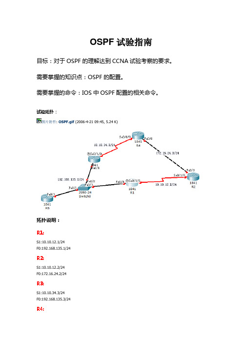
试验拓扑:图片附件: OSPF.gif (2006-4-21 09:45, 5.24 K)拓扑说明:R1:S1:10.10.12.1/24F0:192.168.135.1/24R2:S1:10.10.12.2/24F0:172.16.24.2/24R3:S1:10.10.34.3/24F0:192.168.135.3/24R4:S1:10.10.34.4/24F0:172.16.24.4/24R5:F0:192.168.135.5/24试验要求:1.路由器的IP地址如上所示。
每个路由器都有一个环回口,地址为X.X.X.X/32,X是你的路由器编号,例如: R1的环回口地址为1.1.1.1/32。
2.在所有路由器上开启OSPF路由协议。
3.配置结束后所有路由器都能看到所有网络的路由,并且能够ping通所有IP地址。
配置步骤:一.配置预配R1:Router>enable 进入特权模式Router#configure terminal 进入全局配置模式Router(config)#hostname R1 设置名字R1(config)#enable secret cisco 加密的R1(config)#no ip domain-lookup 关闭自动域名解析R1(config)#line console 0 进入线路con口R1(config-line)#password cisco 设置登陆密码R1(config-line)#login 启用密码R1(config-line)#logging synchronous 关闭同步日志R1(config-line)#exec-timeout 0 0从 con登陆永不超时(试验环境下)R1(config-line)#exitR1 (config)#line vty 0 4 telnet 远程登陆线路口R1 (config-line)#password ciscoR1 (config-line)#loginR1 (config-line)#logging synchronousR1 (config-line)#exec-timeout 0 0R1 (config-line)#exitR2:Router>enable 进入特权模式Router#configure terminal 进入全局配置模式Router(config)#hostname R1 设置名字R2(config)#enable secret cisco 加密的R2(config)#no ip domain-lookup 关闭自动域名解析R2(config)#line console 0 进入线路con口R2(config-line)#password cisco 设置登陆密码R2(config-line)#login 启用密码R2(config-line)#logging synchronous 关闭同步日志R2(config-line)#exec-timeout 0 0从 con登陆永不超时(试验环境下)R2(config-line)#exitR2 (config)#line vty 0 4 telnet 远程登陆线路口R2 (config-line)#password ciscoR2 (config-line)#loginR2 (config-line)#logging synchronousR2 (config-line)#exec-timeout 0 0R2 (config-line)#exitRouter>enable 进入特权模式Router#configure terminal 进入全局配置模式Router(config)#hostname R1 设置名字R3(config)#enable secret cisco 加密的R3(config)#no ip domain-lookup 关闭自动域名解析R3(config)#line console 0 进入线路con口R3(config-line)#password cisco 设置登陆密码R3(config-line)#login 启用密码R3(config-line)#logging synchronous 关闭同步日志R3(config-line)#exec-timeout 0 0从 con登陆永不超时(试验环境下)R3(config-line)#exitR3 (config)#line vty 0 4 telnet 远程登陆线路口R3 (config-line)#password ciscoR3 (config-line)#loginR3 (config-line)#logging synchronousR3 (config-line)#exec-timeout 0 0R3 (config-line)#exitR4:Router>enable 进入特权模式Router#configure terminal 进入全局配置模式Router(config)#hostname R1 设置名字R4(config)#enable secret cisco 加密的R4(config)#no ip domain-lookup 关闭自动域名解析R4(config)#line console 0 进入线路con口R4(config-line)#password cisco 设置登陆密码R4(config-line)#login 启用密码R4(config-line)#logging synchronous 关闭同步日志R4(config-line)#exec-timeout 0 0从 con登陆永不超时(试验环境下)R4(config-line)#exitR4 (config)#line vty 0 4 telnet 远程登陆线路口R4 (config-line)#password ciscoR4 (config-line)#loginR4 (config-line)#logging synchronousR4 (config-line)#exec-timeout 0 0R4 (config-line)#exitRouter>enable 进入特权模式Router#configure terminal 进入全局配置模式Router(config)#hostname R1 设置名字R5(config)#enable secret cisco 加密的R5(config)#no ip domain-lookup 关闭自动域名解析R5(config)#line console 0 进入线路con口R5(config-line)#password cisco 设置登陆密码R5(config-line)#login 启用密码R5(config-line)#logging synchronous 关闭同步日志R5(config-line)#exec-timeout 0 0从 con登陆永不超时(试验环境下)R5(config-line)#exitR5 (config)#line vty 0 4 telnet 远程登陆线路口R5 (config-line)#password ciscoR5 (config-line)#loginR5 (config-line)#logging synchronousR5 (config-line)#exec-timeout 0 0R5 (config-line)#exitSwitch0Switch>enable 用户模式到特权模式Switch#configure terminal 特权模式到全局配置模式Switch(config)#hostname Switch0 设置名字Switch0(config)#enable secret cisco 加密的Switch0(config)#no ip domain-lookup 关闭自动域名解析Switch0(config)#line console 0 进入线路console口Switch0(config-line)#password cisco 设置登陆密码Switch0(config-line)#login 启用密码Switch0(config-line)#logging synchronous 关闭同步日志Switch0(config-line)#exec-timeout 0 0 从 console登陆永不超时(试验环境下)Switch0(config-line)#exit 退出Switch0(config)#line vty 0 4 telnet 远程登陆线路口Switch0(config-line)#password ciscoSwitch0(config-line)#loginSwitch0(config-line)#logging synchronousSwitch0(config-line)#exec-timeout 0 0Switch0(config-line)#exit二、配置各接口IP地址R1:R1(config)#interface fastEthernet 0/0 以太网接口R1(config-if)#ip address 192.168.135.1 255.255.255.0 R1(config-if)#no shutdownR1(config-if)#exitR1(config)#interface serial 0/1/0 串行接口R1(config-if)#ip address 10.10.12.1 255.255.255.0R1(config-if)#clock rate 64000R1(config-if)#no shutdownR1(config-if)#exitR1(config)#interface loopback 0R1(config-if)#ip address 1.1.1.1 255.255.255.255R1(config-if)#no shutdownR1(config-if)#exitR2:R2(config)#interface serial 0/1/0R2(config-if)#ip address 10.10.12.2 255.255.255.0R2(config-if)#no shutdownR1(config-if)#clock rate 64000R2(config)#interface fastEthernet 0/0R2(config-if)#ip address 172.16.24.2 255.255.255.0 R2(config-if)#no shutdownR2(config)#interface loopback 0R2(config-if)#ip address 2.2.2.2 255.255.255.255R2(config-if)#no shutdownR3:R3(config)#interface serial 0/1/0R3(config-if)#ip address 10.10.34.3 255.255.255.0R3(config-if)#no shutdownR1(config-if)#clock rate 64000R3(config)#interface fastEthernet 0/1R3(config-if)#ip address 192.168.135.3 255.255.255.0 R3(config-if)#no shutdownR3(config)#interface loopback 0R3(config-if)#ip address 3.3.3.3 255.255.255.255R3(config-if)#no shutdownR4:R4(config)#interface serial 0/0/0R4(config-if)#ip address 10.10.34.4 255.255.255.0R4(config-if)#no shutdownR1(config-if)#clock rate 64000R4(config)#interface fastEthernet 0/0R4(config-if)#ip address 172.16.24.4 255.255.255.0 R4(config-if)#no shutdownR4(config)#interface loopback 0R4(config-if)#ip address 4.4.4.4 255.255.255.255R4(config-if)#no shutdownR5(config)#interface fastEthernet 0/1R5(config-if)#ip address 192.168.135.5 255.255.255.0 R5(config-if)#no shutdownR5(config)#interface loopback 0R5(config-if)#ip address 5.5.5.5 255.255.255.255R5(config-if)#no shutdown三、配置OSPF协议R1:R1(config)#router ospf 1R1(config-router)#network 10.10.12.1 0.0.0.0 area 0R1(config-router)#network 192.168.135.1 0.0.0.0 area 0 R1(config-router)#network 1.1.1.1 0.0.0.0 area 0R2:R2(config)#router ospf 2R2(config-router)#network 10.10.12.2 0.0.0.0 area 0R2(config-router)#network 172.16.24.2 0.0.0.0 area 0 R2(config-router)#network 2.2.2.2 0.0.0.0 area 0R3:R3(config)#router ospf 3R3(config-router)#network 10.10.34.3 0.0.0.0 area 0R3(config-router)#network 192.168.135.3 0.0.0.0 area 0 R3(config-router)#network 3.3.3.3 0.0.0.0 area 0R4(config)#router ospf 4R4(config-router)#network 10.10.34.4 0.0.0.0 area 0R4(config-router)#network 172.16.24.4 0.0.0.0 area 0 R4(config-router)#network 4.4.4.4 0.0.0.0 area 0R5:R5(config)#router ospf 5R5(config-router)#network 192.168.135.5 0.0.0.0 area 0 R5(config-router)#network 5.5.5.5 0.0.0.0 area 0四、查看配置。
实验8 配置OSPF Totally Stub区域
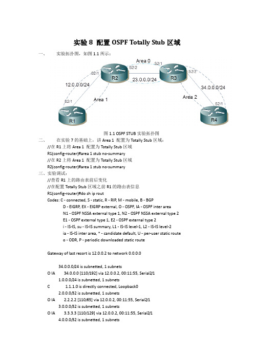
实验8 配置OSPF Totally Stub区域一、实验拓扑图,如图1.1所示:图1.1 OSPF STUB实验拓扑图二、在实验7的基础上,讲Area 1 配置为Totally Stub区域://在R1上将Area 1 配置为Totally Stub区域R1(config-router)#area 1 stub no-summary//在R2上将Area 1 配置为Totally Stub区域R2(config-router)#area 1 stub no-summary三、实验调试://查看R1上的路由表前后变化//在配置Totally Stub区域之前R1的路由表信息R1(config-router)#do sh ip routCodes: C - connected, S - static, R - RIP, M - mobile, B - BGPD - EIGRP, EX - EIGRP external, O - OSPF, IA - OSPF inter areaN1 - OSPF NSSA external type 1, N2 - OSPF NSSA external type 2E1 - OSPF external type 1, E2 - OSPF external type 2i - IS-IS, su - IS-IS summary, L1 - IS-IS level-1, L2 - IS-IS level-2ia - IS-IS inter area, * - candidate default, U - per-user static routeo - ODR, P - periodic downloaded static routeGateway of last resort is 12.0.0.2 to network 0.0.0.034.0.0.0/24 is subnetted, 1 subnetsO IA 34.0.0.0 [110/192] via 12.0.0.2, 00:11:55, Serial2/11.0.0.0/24 is subnetted, 1 subnetsC 1.1.1.0 is directly connected, Loopback02.0.0.0/32 is subnetted, 1 subnetsO IA 2.2.2.2 [110/65] via 12.0.0.2, 00:11:55, Serial2/13.0.0.0/32 is subnetted, 1 subnetsO IA 3.3.3.3 [110/129] via 12.0.0.2, 00:11:55, Serial2/14.0.0.0/32 is subnetted, 1 subnetsO IA 4.4.4.4 [110/193] via 12.0.0.2, 00:11:55, Serial2/123.0.0.0/24 is subnetted, 1 subnetsO IA 23.0.0.0 [110/128] via 12.0.0.2, 00:11:55, Serial2/112.0.0.0/24 is subnetted, 1 subnetsC 12.0.0.0 is directly connected, Serial2/1O*IA 0.0.0.0/0 [110/65] via 12.0.0.2, 00:11:55, Serial2/1//配置Totally Stub区域后R1上的路由表信息R1(config-router)#do sh ip routCodes: C - connected, S - static, R - RIP, M - mobile, B - BGPD - EIGRP, EX - EIGRP external, O - OSPF, IA - OSPF inter areaN1 - OSPF NSSA external type 1, N2 - OSPF NSSA external type 2E1 - OSPF external type 1, E2 - OSPF external type 2i - IS-IS, su - IS-IS summary, L1 - IS-IS level-1, L2 - IS-IS level-2ia - IS-IS inter area, * - candidate default, U - per-user static routeo - ODR, P - periodic downloaded static routeGateway of last resort is 12.0.0.2 to network 0.0.0.01.0.0.0/24 is subnetted, 1 subnetsC 1.1.1.0 is directly connected, Loopback012.0.0.0/24 is subnetted, 1 subnetsC 12.0.0.0 is directly connected, Serial2/1O*IA 0.0.0.0/0 [110/65] via 12.0.0.2, 00:01:33, Serial2/1以上输出结果说明,在Totally Stub区域中隔离了域间和域外路由,并且添加了一条只想ABR 的默认路由,从而可以使Totally Stub区域内的路由器在缩减路由表的情况下正确路由。
OSPF的末节区域与完全末节区域
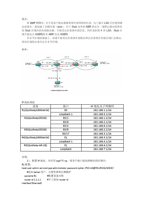
简介:在OSPF网络中,并不是每个路由器都需要外部网络的信息,为了减少LSA泛洪量和路由表条目,就创建了末梢区域(stub),位于Stub边界的ABR将宣告一条默认路由到所有的Stub区域内的内部路由器,不接受自治系统外部信息,同时也拒绝4类LSA,Stub区域不能包含ASBR(除非ABR也是ASBR)在末节区域的基础上,如果不接受自治系统外部路由和自治系统内其他区域汇总路由,则该区域将会成为完全末节区域。
拓扑:实现:1)、配置IP地址,并启用ospf和rip,将各个接口添加到相应的区域中:R1配置:local-user admin service-type administrator password cipher /P.G'J<G@HG-JEXJQ<%DJQ!!#添加telnet用户,方便管理和后期维护sysname R1 #配置设备名称router id 1.1.1.1 #手工添加router idinterface Ethernet0ip address 192.168.1.1 255.255.255.0ospf enable area 0.0.0.1 #在ethernet0上配置为ospf区域1interface LoopBack1ip address 192.168.5.1 255.255.255.0ospf enable area 0.0.0.1 #在loopback上配置ospf区域1R2配置:local-user adminpassword cipher %K/T]3SXOF$[FR9&2:*aF1!!service-type telnet level 3user-interface vty 0 4authentication-mode schemesysname R2router id 2.2.2.2vlan 10vlan 20vlan 30#interface Vlan-interface10ip address 192.168.1.2 255.255.255.0#interface Vlan-interface20ip address 192.168.2.1 255.255.255.0#interface Vlan-interface30ip address 192.168.6.1 255.255.255.0interface NULL0 #启用null接口配置默认路由ospfimport-route direct cost 10 #将R2的直连路由重分发到ospf中import-route rip cost 15 #将rip重分发到ospf中area 0.0.0.1network 192.168.1.2 0.0.0.0#area 0.0.0.0network 192.168.2.1 0.0.0.0ripnetwork 192.168.6.0import-route static cost 10 #将默认路由重分发到rip中#ip route-static 0.0.0.0 0.0.0.0 NULL 0 preference 60 #配置rip网络到ospf的默认路由R3配置:sysname R3router id 3.3.3.3local-user adminpassword cipher Q_E4WOL3a+&AYP51,NO;"A!!service-type telnet level 3user-interface vty 0 4authentication-mode schemevlan 10vlan 20interface Vlan-interface10ip address 192.168.2.2 255.255.255.0#interface Vlan-interface20ip address 192.168.3.1 255.255.255.0ospfarea 0.0.0.2network 192.168.3.1 0.0.0.0#area 0.0.0.0network 192.168.2.2 0.0.0.0R4配置:local-user admin service-type administrator password cipher /P.G'J<G@HG-JEXJQ<%DJQ!!sysname R4router id 4.4.4.4interface Ethernet1ip address 192.168.3.2 255.255.255.0ospf enable area 0.0.0.2interface Ethernet1ip address 192.168.3.2 255.255.255.0ospf enable area 0.0.0.2interface LoopBack1ip address 192.168.4.1 255.255.255.0ospf enable area 0.0.0.2R5配置:sysname R5router id 5.5.5.5local-user adminpasswordcipher .]@USE=B,53Q=^Q`MAF4<<"TX$_S#6.NM(0=0\)*5WWQ=^Q`MAF4<<"TX$_S#6.N service-type telnet terminallevel 3user-interface vty 0 4authentication-mode schemeinterface Ethernet0/1ip address 192.168.6.2 255.255.255.0interface LoopBack1ip address 192.168.7.1 255.255.255.0ripnetwork 192.168.6.0network 192.168.7.02)、查看当前拓扑的歌路由表及其连通性R1:R2:R3:R4:R5:3)、配置区域1为末节区域,屏蔽学到的外部路由,取代为一条默认路由:R1配置:ospf enablestub cost 10 area 0.0.0.1R2配置:ospfimport-route direct cost 10import-route rip cost 15area 0.0.0.1network 192.168.1.2 0.0.0.0stub #将区域1配置为末节区域配置完成后查看新生成的路由表,可以发现原来学到的外部路由没有了,被一条默认路由取代了,但是rip区域的192.168.6.0/24和192.168.7.0/24仍然能ping通通讯测试:4)、配置区域1为完全末节区域:在区域1倍配置为末节区域的同时,关闭ospf类型3和类型4的路由通告,即成为完全末节区域,可以更大程度的减少路由条目R1配置:ospf enablestub cost 10 area 0.0.0.1R2配置:ospfimport-route direct cost 10import-route rip cost 15area 0.0.0.1network 192.168.1.2 0.0.0.0stub no-summary #配置为末节区域,同时关闭域间路由通告查看R1路由表:测试通讯:。
OSPF末节区域和完全末节区域配置
4.4.3 实验10:OSPF末节区域和完全末节区域配置一,实验目的:要掌握:1,末节区域的条件。
2,末节区域的特征。
3,完全末节区域的特征。
4,末节区域和完全末节区域的配置和调试。
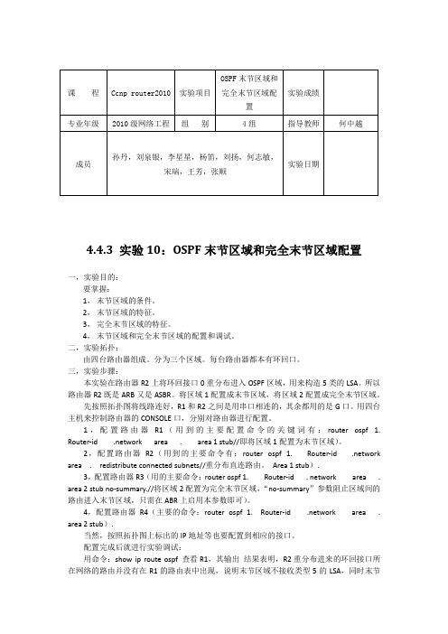
二,实验拓扑:由四台路由器组成。
分为三个区域。
每台路由器都本有环回口。
三,实验步骤:本实验在路由器R2上将环回接口0重分布进入OSPF区域,用来构造5类的LSA。
所以路由器R2既是ARB又是ASBR。
将区域1配置成末节区域,将区域2配置成完全末节区域。
先按照拓扑图将线路连好,R1和R2之间是用串口相连的,其余都用的是G口。
用四台主机来控制路由器的CONSOLE口,分别对路由器进行配置。
1,配置路由器R1(用到的主要配置命令的关键词有:router ospf 1. Router-id .network area . area 1 stub//即将区域1配置为末节区域)。
2,配置路由器R2(用到的主要命令有:router ospf 1. Router-id .network area . redistribute connected subnets//重分布直连路由。
Area 1 stub).3,配置路由器R3(用的主要命令:router ospf 1. Router-id . network area . area 2 stub no-summary.//将区域2配置为完全末节区域,“no-summary”参数阻止区域间的路由进入末节区域,只需在ABR上启用本参数即可)。
4,配置路由器R4(主要的命令:router ospf 1. Router-id .network area . area 2 stub).当然,按照拓扑图上标出的IP地址等也要配置到相应的接口。
配置完成后就进行实验调试:用命令:show ip route ospf 查看R1,其输出结果表明,R2重分布进来的环回接口所在网络的路由并没有在R1的路由表中出现,说明末节区域不接收类型5的LSA,同时末节区域1的ABR R2自动向该区域内传播度量值为1的默认路由;末节区域可以接收区域间路由。
路由器OSPF路由协议配置

R2(config)#router ospf 10 R2(config-ospfv2)#network 30.0.0.0 0.0.0.3 area 0 R2(config-ospfv2)#network 30.0.1.0 0.0.0.3 area 0 R2(config-ospfv2)#exit
内容提要
OSPF配置步骤
OSPF基本配置 OSPF SUTB区域配置 OSPF NSSA区域配置
OSPF路由控制
OSPF故障处理
OSPF路由控制配置
配置OSPF路由聚合(路由配置模式)
配置ABR路由聚合
ZXR10(config-ospfv2)#area <area-id> range <ip-address> <netmask>{ summary-link | nssa-external-link} [advertise| not-advertise]
R2配置:
R2(config)#router ospf 10 R2(config-ospfv2)#router-id 1.1.1.3 R2(config-ospfv2)#network 30.0.0.0 0.0.0.3 area 0 R2(config-ospfv2)#network 30.0.1.0 0.0.0.3 area 1 R2(config-ospfv2)#area 1 stub R2(config-ospfv2)#exit
路由器OSPF路由协议配置
课程目标
经过本节的学习,你可以获得以下收获:
掌握OSPF路由协议的基本配置 掌握OSPF路由协议的配置实例 掌握OSPF路由协议的维护思路
内容提要
OSPF配置步骤
OSPF实验报告-CCNP

Page 4
4
配置
R5: interface Serial1/1 no ip address encapsulation frame-relay serial restart-delay 0 ! interface Serial1/1.1 multipoint ip address 172.8.100.5 255.255.255.0 ip ospf network broadcast frame-relay map ip 172.8.100.4 504 broadcast frame-relay map ip 172.8.100.6 506 broadcast no frame-relay inverse-arp R6: interface Serial1/1 ip address 172.8.100.6 255.255.255.0 encapsulation frame-relay ip ospf network broadcast ip ospf priority 0 serial restart-delay 0 frame-relay map ip 172.8.100.5 605 broadcast no frame-relay inverse-arp 5 R4: interface Serial1/1 ip address 172.8.100.4 255.255.255.0 encapsulation frame-relay ip ospf network broadcast serial restart-delay 0 frame-relay map ip 172.8.100.5 405 broadcast no frame-relay inverse-arp
Page 18
18
末节区域 完全末节区域及NSSA
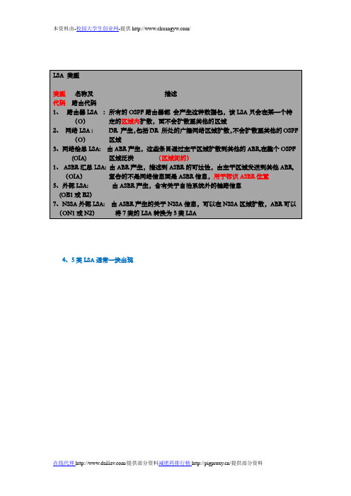
LSA 类型类型名称及描述代码路由代码1、路由器LSA :所有的OSPF路由器都会产生这种数据包,该LSA只会在某一个特(O)定的区域内扩散,面不会扩散至其他的区域2、网络LSA : DR 产生,包括DR 所处的广播网络区域扩散,不会扩散至其他的OSPF(O)区域3、网络绘总LSA: 由ABR产生,这些条目通过主干区域扩散到其他的ABR,在整个OSPF(OIA) 区域泛洪(区域间的)1、ASBR汇总LSA: 由ABR产生,描述到ASBR的可达性,由主干区域发送到其他ABR,(OIA)宣告的不是网络信息面是ASBR信息,用于标识ASBR位置5、外部LSA: 由ASBR产生,含有关于自治系统外的链路信息(OE1或E2)7、NSSA外部LSA: 由ASBR产生的关于NSSA信息,可以在NSSA区域扩散,ABR可以(ON1或N2)将7类的LSA转换为5类LSA4、5类LSA通常一块出现LSA类型1:Router LSA每个区域的每台路由器都会产生一条关于自身的Router LSA: -包含了直连链路的信息列表.-通过IP前缀对链路进行鉴别.通过源路由器的RID进行鉴别.只在本区域内进行洪泛,不会穿越ABR.LSA类型2:Network LSANetwork LSA仍然是产生于本区域的:-描述了所有和DR相连的路由器的信息(包括DR本身).-包含链路的子网掩码.只要是多路访问型网络环境中,DR都会产生Network LSA.本区域洪泛,不会穿越ABR.LSA类型3:Network Summary LSANetwork Summary LSAs 用来把本区域的网络信息传播到其他区域中去: -描述了网络号和掩码信息.由ABR产生.Network Summary LSA会在整个OSPF路由域中洪泛.LSA类型4:ASBR Summary LSAASBR Summary LSA宣告的信息不是网络,而是ASBR信息.仍然是由ABR产生.在整个OSPF路由域中洪泛.后续的ABR将对ASBR Summary LSA重新生成.它只包含ASBR的RID信息.LSA类型5:AS External LSAAS External LSAs 用来宣告OSPF路由域外部的网络信息.由ASBR产生.在整个OSPF路由域中洪泛滥.AS Summary LSA用来查找出ASBR的信息.区域类型1、标准区域:可以接受链路更新信息和路由汇总;2、主干区域:连接各个区域的中心实体,所有的其他的区域都要连接到这个区域上交换路由信息。
OSPFStub(末梢区域)和TotallyStub(完全末梢区域)的配置
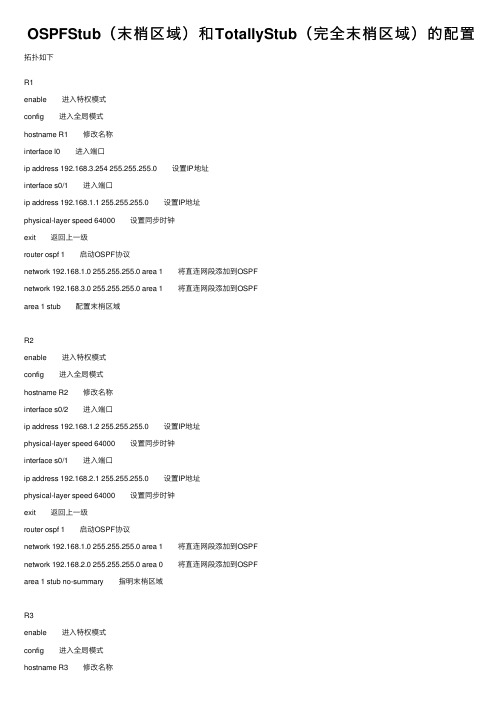
OSPFStub(末梢区域)和TotallyStub(完全末梢区域)的配置拓扑如下R1enable 进⼊特权模式config 进⼊全局模式hostname R1 修改名称interface l0 进⼊端⼝ip address 192.168.3.254 255.255.255.0 设置IP地址interface s0/1 进⼊端⼝ip address 192.168.1.1 255.255.255.0 设置IP地址physical-layer speed 64000 设置同步时钟exit 返回上⼀级router ospf 1 启动OSPF协议network 192.168.1.0 255.255.255.0 area 1 将直连⽹段添加到OSPFnetwork 192.168.3.0 255.255.255.0 area 1 将直连⽹段添加到OSPFarea 1 stub 配置末梢区域R2enable 进⼊特权模式config 进⼊全局模式hostname R2 修改名称interface s0/2 进⼊端⼝ip address 192.168.1.2 255.255.255.0 设置IP地址physical-layer speed 64000 设置同步时钟interface s0/1 进⼊端⼝ip address 192.168.2.1 255.255.255.0 设置IP地址physical-layer speed 64000 设置同步时钟exit 返回上⼀级router ospf 1 启动OSPF协议network 192.168.1.0 255.255.255.0 area 1 将直连⽹段添加到OSPFnetwork 192.168.2.0 255.255.255.0 area 0 将直连⽹段添加到OSPFarea 1 stub no-summary 指明末梢区域R3enable 进⼊特权模式config 进⼊全局模式hostname R3 修改名称interface l0 进⼊端⼝ip address 192.168.4.254 255.255.255.0 设置IP地址interface s0/2 进⼊端⼝ip address 192.168.2.2 255.255.255.0 设置IP地址physical-layer speed 64000 设置同步时钟exit 返回上⼀级router ospf 1 启动OSPF协议network 192.168.4.0 255.255.255.0 area 0 将直连⽹段添加到OSPF network 192.168.2.0 255.255.255.0 area 0 将直连⽹段添加到OSPF相关命令area [区域ID] stub 将指定区域内的路由器配置成末梢区域area [区域ID] stub no-summary 在ABR上指明末梢区域。
OSPF 末节区域和完全末节区域
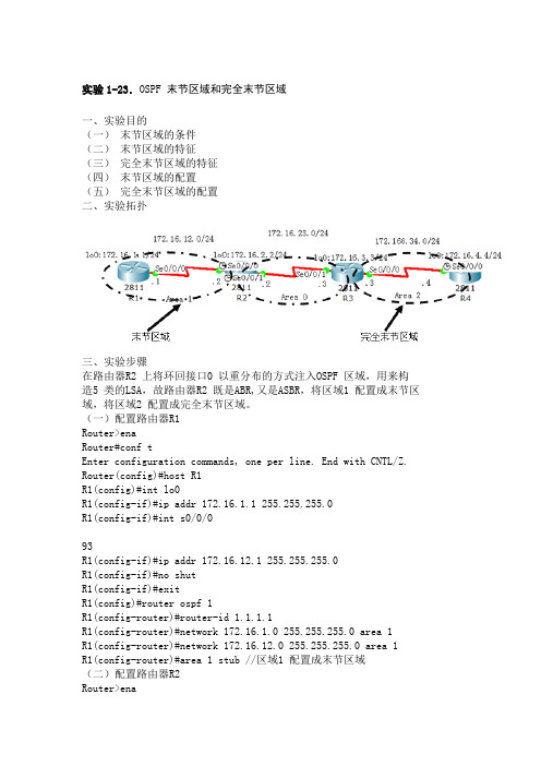
实验1-23.OSPF 末节区域和完全末节区域一、实验目的(一)末节区域的条件(二)末节区域的特征(三)完全末节区域的特征(四)末节区域的配置(五)完全末节区域的配置二、实验拓扑三、实验步骤在路由器R2 上将环回接口0 以重分布的方式注入OSPF 区域,用来构造5 类的LSA,故路由器R2 既是ABR,又是ASBR,将区域1 配置成末节区域,将区域2 配置成完全末节区域。
(一)配置路由器R1Router>enaRouter#conf tEnter configuration commands, one per line. End with CNTL/Z. Router(config)#host R1R1(config)#int lo0R1(config-if)#ip addr 172.16.1.1 255.255.255.0R1(config-if)#int s0/0/093R1(config-if)#ip addr 172.16.12.1 255.255.255.0R1(config-if)#no shutR1(config-if)#exitR1(config)#router ospf 1R1(config-router)#router-id 1.1.1.1R1(config-router)#network 172.16.1.0 255.255.255.0 area 1R1(config-router)#network 172.16.12.0 255.255.255.0 area 1R1(config-router)#area 1 stub //区域1 配置成末节区域(二)配置路由器R2Router>enaRouter#conf tEnter configuration commands, one per line. End with CNTL/Z.Router(config)#host R2R2(config)#int lo0R2(config-if)#ip addr 172.16.2.2 255.255.255.0R2(config-if)#int s0/0/0R2(config-if)#ip addr 172.16.12.2 255.255.255.0R2(config-if)#clock rate 128000R2(config-if)#no shutR2(config-if)#int s0/0/1R2(config-if)#ip addr 172.16.23.2 255.255.255.0R2(config-if)#clock rate 128000R2(config-if)#no shutR2(config-if)#exitR2(config)#router ospf 1R2(config-router)#router-id 2.2.2.2R2(config-router)#network 172.16.12.0 255.255.255.0 area 1R2(config-router)#network 172.16.23.0 255.255.255.0 area 0R2(config-router)#redistribute connected subnets //将直连路由重分布到OSPF 区域R2(config-router)#area 1 stub(三)配置路由器R3Router>enaRouter#conf tEnter configuration commands, one per line. End with CNTL/Z.Router(config)#host R3R3(config)#int lo0R3(config-if)#ip addr 172.16.3.3 255.255.255.0R3(config-if)#int s0/0/1R3(config-if)#ip addr 172.16.23.3 255.255.255.0R3(config-if)#no shutR3(config-if)#int s0/0/0R3(config-if)#ip addr 172.16.34.3 255.255.255.094R3(config-if)#no shutR3(config-if)#exitR3(config)#router ospf 1R3(config-router)#router-id 3.3.3.3R3(config-router)#network 172.16.3.0 255.255.255.0 area 0R3(config-router)#network 172.16.23.0 255.255.255.0 area 0R3(config-router)#network 172.16.34.0 255.255.255.0 area 2R3(config-router)#area 2 stub no-summary //将区域2 配置成完全末节区域(四)配置路由器R4Router>enaRouter#conf tEnter configuration commands, one per line. End with CNTL/Z. Router(config)#host R4R4(config)#int lo0R4(config-if)#ip addr 172.16.4.4 255.255.255.0R4(config-if)#int s0/0/0R4(config-if)#ip addr 172.16.34.4 255.255.255.0R4(config-if)#clock rate 128000R4(config-if)#no shutR4(config-if)#exitR4(config)#router ospf 1R4(config-router)#router-id 4.4.4.4R4(config-router)#network 172.16.4.0 0.0.0.255 area 2R4(config-router)#network 172.16.34.0 0.0.0.255 area 2R4(config-router)#area 2 stub【技术要点】末节和完全末节区域需要满足的条件:区域只有一个出口区域不需要作为虚链路的过渡区区域内没有ASBR区域不是主干区域四、实验调试(一)show ip route ospfR1#show ip route ospf172.16.0.0/16 is variably subnetted, 6 subnets, 2 masksO IA 172.16.3.3 [110/129] via 172.16.12.2, 00:06:49, Serial0/0/0 O IA 172.16.4.4 [110/193] via 172.16.12.2, 00:02:29, Serial0/0/0 O IA 172.16.23.0 [110/128] via 172.16.12.2, 00:08:49, Serial0/0/095O IA 172.16.34.0 [110/192] via 172.16.12.2, 00:03:49, Serial0/0/0 O*IA 0.0.0.0/0 [110/65] via 172.16.12.2, 00:11:30, Serial0/0/0//末节区域可以接收区域间路由,不接收外部自治系统的路由R4#show ip route ospfO*IA 0.0.0.0/0 [110/65] via 172.16.34.3, 00:04:55, Serial0/0/0//完全末节区域不接收外部路由和区域间路由(二)show ip ospfR1#show ip ospf 1[略]Area 1Number of interfaces in this area is 2It is a stub areaArea has no authenticationSPF algorithm executed 8 timesArea ranges areNumber of LSA 7. Checksum Sum 0x0283d1Number of opaque link LSA 0. Checksum Sum 0x000000Number of DCbitless LSA 0Number of indication LSA 0Number of DoNotAge LSA 0Flood list length 0R3#show ip ospf 1Routing Process "ospf 1" with ID 3.3.3.3Supports only single TOS(TOS0) routesSupports opaque LSAIt is an area border routerSPF schedule delay 5 secs, Hold time between two SPFs 10 secs Minimum LSA interval 5 secs. Minimum LSA arrival 1 secs Number of external LSA 1. Checksum Sum 0x00f207Number of opaque AS LSA 0. Checksum Sum 0x000000Number of DCbitless external and opaque AS LSA 0Number of DoNotAge external and opaque AS LSA 0Number of areas in this router is 2. 1 normal 1 stub 0 nssa External flood list length 0Area BACKBONE(0)Number of interfaces in this area is 2Area has no authenticationSPF algorithm executed 5 timesArea ranges areNumber of LSA 6. Checksum Sum 0x039ea3Number of opaque link LSA 0. Checksum Sum 0x00000096Number of DCbitless LSA 0Number of indication LSA 0Number of DoNotAge LSA 0Flood list length 0Area 2Number of interfaces in this area is 1It is a stub areagenerates stub default route with cost 1Area has no authenticationSPF algorithm executed 4 timesArea ranges areNumber of LSA 3. Checksum Sum 0x0142e7Number of opaque link LSA 0. Checksum Sum 0x000000Number of DCbitless LSA 0Number of indication LSA 0 Number of DoNotAge LSA 0 Flood list length 0。
OSPF配置末梢区域
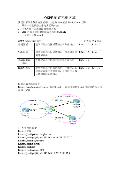
OSPF配置末梢区域满足以下四个条件的区域可以认定为Stub或者Totally Stub 区域1、只有一个默认路由作为其区域的出口2、区域不能作为虚链路的穿越区域3、Stub 区域里无自治系统边界路由器ASBR4、不是骨干区域area 0配置末梢区域的命令Router(config-router)=area 区域号stub 此命令需要在stub区域内的所有路由器上配置1、配置路由器IPRouter1配置Router1(config)#inter loopback 0Router1(config-if)#ip add 192.168.10.10 255.255.255.0Router1(config-if)#no shutRouter1(config-if)#exiRouter1(config)#Router1(config)#inter f0/0Router1(config-if)#ip add 192.168.1.1 255.255.255.0Router1(config-if)#no shutRouter2配置Router2(config)#inter f1/0Router2(config-if)#ip add 192.168.1.2 255.255.255.0Router2(config-if)#no shutRouter2(config)#inter f0/0Router2(config-if)#ip add 192.168.2.1 255.255.255.0Router2(config-if)#no shutRouter2(config)#inter f0/1Router2(config-if)#ip add 192.168.3.1 255.255.255.0Router2(config-if)#no shutRouter3配置Router(config)#inter loopback 0Router(config-if)#ip add 192.168.20.10 255.255.255.0 Router(config-if)#no shutRouter(config)#Router(config)#inter f0/0Router(config-if)#ip add 192.168.2.2 255.255.255.0Router(config-if)#no shutRouter4配置Router(config)#inter loopback 0Router(config-if)#ip add 192.168.30.10 255.255.255.0 Router(config-if)#no shutRouter(config-if)#exiRouter(config)#inter f0/1Router(config-if)#ip add 192.168.3.2 255.255.255.0Router(config-if)#no shut2、配置各个路由器的OSPFArea 0 区域Router1outer1(config)#router ospf 1Router1(config-router)#netRouter1(config-router)#network 192.168.10.0 0.0.0.255 a Router1(config-router)#network 192.168.10.0 0.0.0.255 area 0 Router1(config-router)#network 192.168.1.0 0.0.0.255 area 0 Router1(config-router)#区域边界路由器ASBR Router2Router2(config)#router ospf 2Router2(config-router)#network 192.168.1.0 0.0.0.255 area 0Router2(config-router)#network 192.168.2.0 0.0.0.255 area 1Router2(config-router)#network 192.168.3.0 0.0.0.255 area 1Router2(config-router)#area 1 stubRouter2(config-router)#exiStub区域Router3 和Router4Router3 (config)#router ospf 3Router3 (config-router)#network 192.168.20.0 0.0.0.255 area 1Router3 (config-router)#network 192.168.2.0 0.0.0.255 area 1Router3 (config-router)#area 1 stubRouter3 (config-router)#exiRouter3 (config)#Router4(config)#route ospf 4Router4(config-router)#network 192.168.30.0 0.0.0.255 area 1Router4(config-router)#network 192.168.3.0 0.0.0.255 area 1Router4(config-router)#area 1 stubRouter4(config-router)#exiRouter4(config)#3、查看路由器路的路由表Router2Router2#show ip routeCodes: C - connected, S - static, I - IGRP, R - RIP, M - mobile, B - BGPD - EIGRP, EX - EIGRP external, O - OSPF, IA - OSPF inter areaN1 - OSPF NSSA external type 1, N2 - OSPF NSSA external type 2E1 - OSPF external type 1, E2 - OSPF external type 2, E - EGPi - IS-IS, L1 - IS-IS level-1, L2 - IS-IS level-2, ia - IS-IS inter area* - candidate default, U - per-user static route, o - ODRP - periodic downloaded static routeGateway of last resort is not setC 192.168.1.0/24 is directly connected, FastEthernet1/0C 192.168.2.0/24 is directly connected, FastEthernet0/0C 192.168.3.0/24 is directly connected, FastEthernet0/1192.168.10.0/32 is subnetted, 1 subnetsO 192.168.10.10 [110/2] via 192.168.1.1, 00:05:03, FastEthernet1/0 192.168.20.0/32 is subnetted, 1 subnetsO 192.168.20.10 [110/2] via 192.168.2.2, 00:02:37, FastEthernet0/0 192.168.30.0/32 is subnetted, 1 subnetsO 192.168.30.10 [110/2] via 192.168.3.2, 00:00:54, FastEthernet0/1。
末节区域 完全末节区域及NSSA

LSA 类型类型名称及描述代码路由代码1、路由器LSA :所有的OSPF路由器都会产生这种数据包,该LSA只会在某一个特(O)定的区域内扩散,面不会扩散至其他的区域2、网络LSA : DR 产生,包括DR 所处的广播网络区域扩散,不会扩散至其他的OSPF(O)区域3、网络绘总LSA: 由ABR产生,这些条目通过主干区域扩散到其他的ABR,在整个OSPF(OIA) 区域泛洪(区域间的)1、ASBR汇总LSA: 由ABR产生,描述到ASBR的可达性,由主干区域发送到其他ABR,(OIA)宣告的不是网络信息面是ASBR信息,用于标识ASBR位置5、外部LSA: 由ASBR产生,含有关于自治系统外的链路信息(OE1或E2)7、NSSA外部LSA: 由ASBR产生的关于NSSA信息,可以在NSSA区域扩散,ABR可以(ON1或N2)将7类的LSA转换为5类LSA4、5类LSA通常一块出现LSA类型1:Router LSA每个区域的每台路由器都会产生一条关于自身的Router LSA: -包含了直连链路的信息列表.-通过IP前缀对链路进行鉴别.通过源路由器的RID进行鉴别.只在本区域内进行洪泛,不会穿越ABR.LSA类型2:Network LSANetwork LSA仍然是产生于本区域的:-描述了所有和DR相连的路由器的信息(包括DR本身).-包含链路的子网掩码.只要是多路访问型网络环境中,DR都会产生Network LSA.本区域洪泛,不会穿越ABR.LSA类型3:Network Summary LSANetwork Summary LSAs 用来把本区域的网络信息传播到其他区域中去: -描述了网络号和掩码信息.由ABR产生.Network Summary LSA会在整个OSPF路由域中洪泛.LSA类型4:ASBR Summary LSAASBR Summary LSA宣告的信息不是网络,而是ASBR信息.仍然是由ABR产生.在整个OSPF路由域中洪泛.后续的ABR将对ASBR Summary LSA重新生成.它只包含ASBR的RID信息.LSA类型5:AS External LSAAS External LSAs 用来宣告OSPF路由域外部的网络信息.由ASBR产生.在整个OSPF路由域中洪泛滥.AS Summary LSA用来查找出ASBR的信息.区域类型1、标准区域:可以接受链路更新信息和路由汇总;2、主干区域:连接各个区域的中心实体,所有的其他的区域都要连接到这个区域上交换路由信息。
思科路由器OSPF协议实验
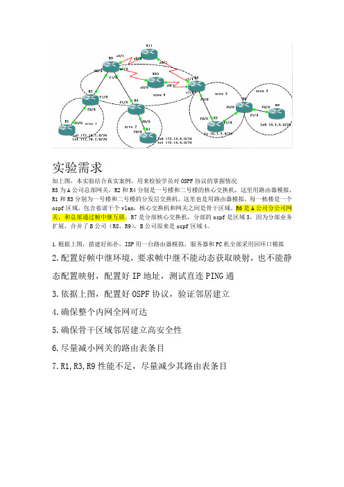
实验需求如上图,本实验结合真实案例,用来检验学员对OSPF协议的掌握情况R5为A公司总部网关,R2和R4分别是一号楼和二号楼的核心交换机,这里用路由器模拟,R1和R3分别为一号楼和二号楼的分发层交换机,这里也是用路由器模拟,每一栋楼是一个ospf区域,包含着诺干个vlan,核心交换机和网关之间是骨干区域。
R6是A公司分公司网关,和总部通过帧中继互联,R7是分部核心交换机,分部的ospf是区域3,因为分部业务扩展,合并了B公司(R8,R9),B公司原来是ospf区域4。
1.根据上图,搭建好拓扑,ISP用一台路由器模拟,服务器和PC机全部采用回环口模拟2.配置好帧中继环境,要求帧中继不能动态获取映射,也不能静态配置映射,配置好IP地址,测试直连PING通3.依据上图,配置好OSPF协议,验证邻居建立4.确保整个内网全网可达5.确保骨干区域邻居建立高安全性6.尽量减小网关的路由表条目7.R1,R3,R9性能不足,尽量减少其路由表条目实验步骤1、对各路由器配置IP地址2、将R10模拟为帧中继R10#conf tR10(config)#frame-relay swiR10(config)#frame-relay switchingR10(config)#int s0/0R10(config-if)#no shutR10(config-if)#encapsulation frame-relayR10(config-if)#frame-relay intf-type dceR10(config-if)#clock rate 64000R10(config-if)#frame-relay route 506 int s0/1 605R10(config-if)#int s0/1R10(config-if)#encapsulation frame-relayR10(config-if)#frame-relay intf-type dceR10(config-if)#clock rate 64000R10(config-if)#frame-relay route 605 int s0/0 506R10(config-if)#exit在R5的s2/0,及R6的s1/0做相应的帧中继封装R5(config)#int s2/0R5(config-if)#encapsulation frame-relayR5(config-if)#frame-relay intf-type dteR5(config-if)#exitR6(config)#int s1/0R6(config-if)#encapsulation frame-relayR6(config-if)#frame-relay intf-type dteR6(config-if)#exit3、配置OSPF协议,并验证邻居建立R1(config)#router ospf 1R1(config-router)#router-idR1(config-router)#router-id 1.1.1.1R1(config-router)#net 172.16.3.1 0.0.0.0 a 1R1(config-router)#exit其他路由器的配置命令类似在R10帧中继线路上,R5的接口s2/0与R6接口s1/0的OSPF类型为非广播因此不能产生Hello包以建立OSPF邻居。
OSPF详细配置+详解
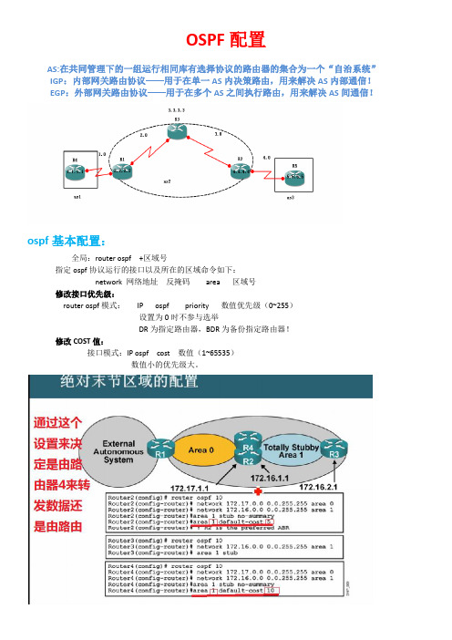
OSPF配置AS:在共同管理下的一组运行相同库有选择协议的路由器的集合为一个“自治系统”IGP:内部网关路由协议——用于在单一AS内决策路由,用来解决AS内部通信!EGP:外部网关路由协议——用于在多个AS之间执行路由,用来解决AS间通信!ospf基本配置:全局:router ospf +区域号指定ospf协议运行的接口以及所在的区域命令如下:network 网络地址反掩码area 区域号修改接口优先级:router ospf模式:IP ospf priority 数值优先级(0~255)设置为0时不参与选举DR为指定路由器,BDR为备份指定路由器!修改COST值:接口模式:IP ospf cost 数值(1~65535)数值小的优先级大。
查看ospf配置:路由表:show IP route邻居列表及状态:show IP router ospf neighborospf配置:show IP ospfospf 多区域配置ABR(区域边界路由器):连接一个或多个区域到骨干区域的路由器,并且这些路由器会作为间通信量的路由网关ASBR:(自治系统边界路由器):可以认为它是ospf域外部的通信量进入ospf域的网关路由器洪扩散。
●组成员LSA(LSA6):是用在OSPF协议的一个增强版本――组播OSPF协议(MOSPF协议)中的。
MOSPF协议将数据包从一个单一的源地址转发到多个目的地,或者是一组共享D类组播地址的成员。
●NSSA外部LSA(LSA7):是指在非纯末梢区域(Not-So-Stubby Area,NSSA)内始发于ASBR路由器的LSA通告。
NSSA外部LSA通告几乎和自主系统外部LSA通告是相同的。
只是不像自主系统外部LSA通告那样在整个OSPF自主系统内进行泛洪扩散,NSSA外部LSA通告仅仅在始发这个NSSA外部LSA通告的非纯末梢区域内部进行泛洪扩散。
●外部属性LSA(LSA8):是被提议作为运行内部BGP协议(iBGP协议)的另一种选择,以便用来传送BGP协议的信息穿过一个OSPF域。
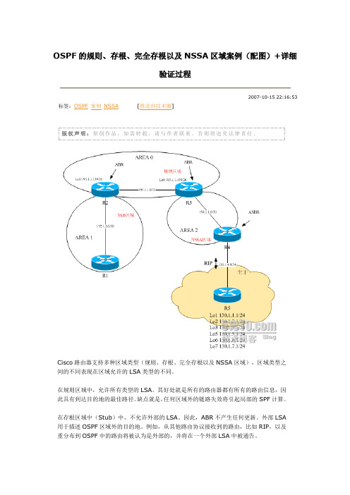
OSPF的规则、存根、完全存根以及NSSA区域案例(配图)+详细验证过程
版权声明:原创作品,如需转载,请与作者联系。
否则将追究法律责任。
Cisco路由器支持多种区域类型(规则、存根、完全存根以及NSSA区域),区域类型之间的不同表现在区域允许的LSA类型的不同。
在规则区域中,允许所有类型的LSA。
其好处就是所有的路由器都有所有的路由信息,因此具有到达目的地的最佳路径。
缺点就是,任何区域外的链路失效将引起局部的SPF计算。
在存根区域中(Stub)中,不允许外部的LSA。
因此,ABR不产生任何更新。
外部LSA 用于描述OSPF区域外的目的地。
例如,从其他路由协议接收到的路由,比如RIP,以及重分布到OSPF中的路由将被认为是外部的,并将在一个外部LSA中被通告。
虽然存根区域可以防止外部区域对区域的影响,但它们并不阻止区域内对区域的影响。
因为仍然允许汇总LSA,所以,其他区域将仍然影响到存根区域。
完全存根区域(Totally Stub)区域同存根区域类似,将阻止外部LSA。
但是,同存根区域不同的是,完全存根区域不允许汇总LSA。
这样其他区域将不影响完全存根区域。
NSSA区域同存根区域类似,但是,它可以将外部路由导入到区域中。
区域间的路由为类型7的LSA,并被ABR转换为类型5的LSA。
例如,如果你需要阻止外部LSA进入该区域,但仍需要向区域外部发送外部LSA(例如,如果区域中的某个路由器为ASBR),就需要使用NSSA区域。
基本配置如下:// R1 //int e0/0ip ad 192.1.1.1 255.255.255.252router os 1network 192.1.1.1 0.0.0.0 area 1// R2 //int e0/0ip ad 192.1.1.2 255.255.255.252int lo0ip ad 193.1.1.129 255.255.255.192ip ospf network point-to-point //变主机路由为网段路由int e1/0ip ad 193.1.1.2 255.255.255.128router os 1network 192.1.1.2 0.0.0.0 area 1network 193.1.1.129 0.0.0.0 area 0network 193.1.1.2 0.0.0.0 area 0area 0 range 193.1.1.0 255.255.255.0 //区域汇总// R3 //int e1/0ip ad 193.1.1.3 255.255.255.128int lo0ip ad 193.1.1.193 255.255.255.192ip ospf network point-to-point //变主机路由为网段路由int e0/0ip ad 194.1.1.1 255.255.255.252router os 1network 193.1.1.3 0.0.0.0 area 0network 193.1.1.193 0.0.0.0 area 0network 194.1.1.1 0.0.0.0 area 2area 0 range 193.1.1.0 255.255.255.0 //区域汇总// R4 //int e0/0ip ad 194.1.1.2 255.255.255.252int e1/0ip ad 130.1.4.4 255.255.255.0rotuer os 1netw 194.1.1.2 0.0.0.0 area 2summary-address 130.1.0.0 255.255.248.0 //外部路由汇总router ripnetw 130.1.0.0// R5 //int e1/0ip ad 130.1.4.5 255.255.255.0int lo1ip ad 130.1.1.1 255.255.255.0int lo2ip ad 130.1.2.1 255.255.255.0int lo3ip ad 130.1.3.1 255.255.255.0int lo5ip ad 130.1.5.1 255.255.255.0int lo6ip ad 130.1.6.1 255.255.255.0int lo7ip ad 130.1.7.1 255.255.255.0router ripnetwork 130.1.0.0基本配置完成后,先进行验证:r1#sh ip ro130.1.0.0/21 is subnetted, 1 subnetsO E2 130.1.0.0 [110/10] via 192.1.1.2, 00:00:02, Ethernet0/0O IA 193.1.1.0/24 [110/11] via 192.1.1.2, 00:00:02, Ethernet0/0 192.1.1.0/30 is subnetted, 1 subnetsC 192.1.1.0 is directly connected, Ethernet0/0194.1.1.0/30 is subnetted, 1 subnetsO IA 194.1.1.0 [110/30] via 192.1.1.2, 00:00:02, Ethernet0/0我们观察到了区域间路由以及外部路由。
OSPF末梢区域的设置
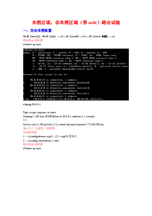
末梢区域,非末梢区域(带asdr)路由试验一:完全末梢配置:30 40(area2),50 60(rip)----r3---10(area0)---r1----20(area1末梢)---r2路由器r1的配置r1#show ip router1#ping 30.0.0.1Type escape sequence to abort.Sending 5, 100-byte ICMP Echos to 30.0.0.1, timeout is 2 seconds:!!!!!Success rate is 100 percent (5/5), round-trip min/avg/max = 72/108/208 ms通~!!!!!完成第一步配置!开始做末梢:1)r1(config)#router ospf 1 进入ospf配置模式2)r1(config-router)#area 1 stub路由器r2的配置r2#show ip route3)r2(config)#router ospf 1 进入ospf配置模式4)r2(config-router)#area 1 stub5)r2#show ip route再次查看路由表r1#show ip route查看r1路由表R1路由表不变R1与r2上的无汇总的路由(去除3类的lsa)1)接上2)r2(config)#router ospf 1 进入ospf路由配置模式3)r2(config-router)#area 1 stub no-summary 无汇总的命令4)r1(config)#router ospf 15)r1(config-router)#area 1 stub no-summaryr1#show ip router2#show ip route再次检测r2#ping 70.0.0.1Type escape sequence to abort.Sending 5, 100-byte ICMP Echos to 70.0.0.1, timeout is 2 seconds:!!!!!Success rate is 100 percent (5/5), round-trip min/avg/max = 72/94/136 ms完成!!!!!!!!!二nssa的区域配置(接收7类lsa)30 40(area2),50 60(rip)----r3---10(area0 nssa)---r1----20(area1)---r2 1ri的配置如下r1(config)#router ospf 1 进入ospf配置模式r1(config-router)#no area 1 stub 取消area1末梢区r1(config-router)#area 1 nssa 设置为nssar2的配置如下:r2(config)#router ospf 1r2(config-router)#no area 1 stubr2(config-router)#area 1 nssar2#show ip router1#show ip router1(config)#router ospf 1r1(config-router)#area 1 nssa no-summary r2(config)#router ospf 1r2(config-router)#area 1 nssa no-summary r1#show ip router2#show ip route。
OSPF高级实验手册
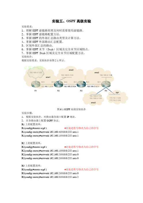
实验五、OSPF高级实验实验要求:1、理解OSPF虚链路原理及何时需要使用虚链路。
2、掌握OSPF虚链路配置方法。
3、掌握OSPF的外部汇总路由类型及计算方法。
4、掌握OSPF外部路由汇总配置。
5、区别外部汇总的路由。
6、掌握OSPF末节(Stub)区域及完全末节区域特点。
7、掌握OSPF Stub区域及完全末节区域配置方法。
实验拓扑:根据实验要求,实验拓扑如图2-1所示。
图6-1 OSPF高级实验拓扑实验步骤:1、根据实验拓扑,对路由器各接口配置IP地址。
2、在各路由器上配置OSPF协议。
R1上的配置清单:R1(config)#router ospf 1 #此处进程号修改为自己的学号R1(config-router)#network 192.168.4.0 0.0.0.255 area 1R1(config-router)#network 192.168.1.0 0.0.0.255 area 1R2上的配置清单:R2(config)#router ospf 1 #此处进程号修改为自己的学号R2(config-router)#network 192.168.1.0 0.0.0.255 area 1R2(config-router)#network 192.168.5.0 0.0.0.255 area 0R2(config-router)#network 192.168.2.0 0.0.0.255 area 0R3上的配置清单:R3(config)#router ospf 1 #此处进程号修改为自己的学号R3(config-router)#network 192.168.2.0 0.0.0.255 area 0R3(config-router)#network 192.168.3.0 0.0.0.255 area 2R4上的配置清单:R4(config)#router ospf 1 #此处进程号修改为自己的学号R4(config-router)# network 192.168.6.0 0.0.0.255 area 2R4(config-router)# network 192.168.3.0 0.0.0.255 area 2 注:这里没有添加area33、在R4上配置R4(config)#router ospf 1 #此处进程号修改为自己的学号R4(config-router)# network 192.168.8.0 0.0.0.255 area 3R4(config-router)# network 192.168.9.0 0.0.0.255 area 3问题1:配置后在R1中查看路由表,能否看到192.168.8.0和192.168.9.0的路由,原因是什么?问题2:在R3和R4中分别用show ip ospf来查看路由ID,这两个路由器的路由ID分别是什么?问题3:在R3中查看OSPF数据库,看有几条类型1(即路由链路状态)3、配置在R3和R4上虚拟链路R3(config)#router ospf 1 #此处进程号修改为自己的学号R3(config-router)#area 2 virtual-link 192.168.8.1 注,此处为路由器R4的路由IDR4(config)#router ospf 1 #此处进程号修改为自己的学号R4(config-router)#area 2 virtual-link 192.168.3.3 注,此处为路由器R3的路由ID问题3:在R3中查看OSPF数据库,看有几条类型1(即路由链路状态)问题4:此时在R1中查看路由表,和原来有什么变化?4、在R4上配置RIP路由选择协议R4(config)#router ripR4(config-router)#version 2R4(config-router)#network 172.16.0.05、在R4上对OSPF和RIP做路由重分发,参考命令如下R4(config)#router ospf 1 #此处进程号修改为自己的学号R4(config-router)#redistribute rip metric 200 subnetsR4(config)#router ripR4(config-router)#redistribute ospf 1 metric 10问题5:在路由器R1上查看路由表有什么变化?类型E2的路由有几条?问题6:在R1上查看OSPF数据库,类型4的链路有几条?链路ID是多少?问题7:在R1上查看OSPF数据库,类型5的链路有几条?链路ID是多少?6、为了减少路由条目,在R4上进行自制系统外部路由汇总,参考命令为R4(config)#router ospf 1 #此处进程号修改为自己的学号R4(config-router)#summary-address 172.16.0.0 255.255.0.0问题8:此时在R1上查看路由表,类型为E2的路由还有几条?7、为了减少区域1的路由条目,把区域1设为存根网络,即不接受类型4和类型5的路由。
OSPF的多区域配置

03
区域内的路由器之间交换链路 状态信息,并通过区域内路由 汇总和过滤,减少路由器的资 源消耗。
02 多区域OSPF配置
配置多区域OSPF
创建多个OSPF区域
在OSPF路由器上创建多个区域,每个区域运行一个OSPF实例, 维护一个区域内路由数据库。
配置区域ID
为每个区域分配一个唯一的区域ID,用于标识该区域。
配置区域间路由的优先级
根据不同区域的优先级需,配置相应的区 域间路由优先级,确保关键业务的路由稳定 性。
优化区域内路由
优化区域内路由的路径
根据实际网络环境和业务需求,优化区域内路 由的路径选择,提高路由的稳定性和可靠性。
配置区域内路由的优先级
根据不同区域的优先级需求,配置相应的区域 内路由优先级,确保关键业务的路由稳定性。
THANKS FOR WATCHING
感谢您的观看
案例三:数据中心多区域OSPF配置
总结词
适用于数据中心网络,需要实现服务器和存储设备的 互联互通
详细描述
在数据中心网络中,通常会有多个数据中心,每个数据 中心内部配置有服务器和存储设备。为了实现服务器和 存储设备之间的互联互通,可以采用多区域OSPF配置。 在每个数据中心内部的局域网配置OSPF,并通过数据 中心的核心交换机将各局域网互联互通。同时,需要合 理规划各数据中心之间的网络拓扑和OSPF参数,以确 保网络的稳定性和可靠性。此外,还需要考虑数据中心 内部的安全性和可靠性,如采用冗余设备和链路等措施。
配置OSPF快速收敛
通过配置OSPF快速收敛相关参数(如Fast Hello Timer、Fast Retransmit等),提高 OSPF的收敛速度和稳定性。
04 OSPF多区域故障排除
ospf的末节区域实验报告
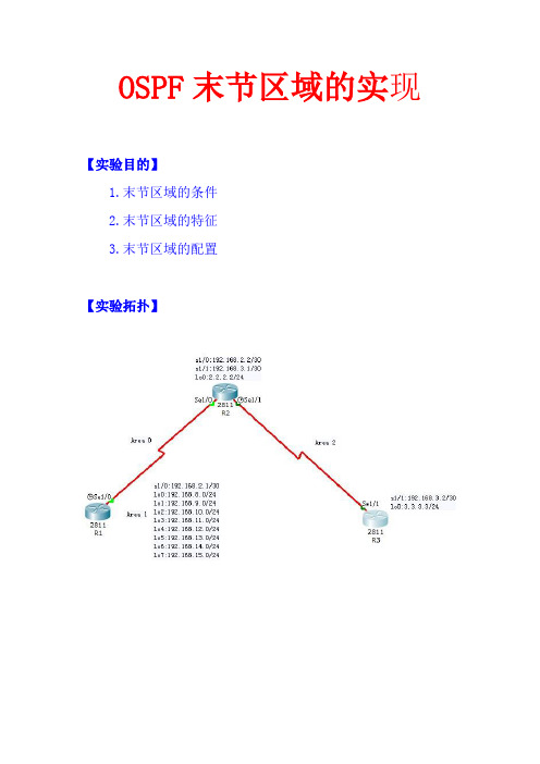
OSPF末节区域的实现【实验目的】1.末节区域的条件2.末节区域的特征3.末节区域的配置【实验拓扑】【步骤1】在r1在配置r1(config)#int s1/0r1(config-if)#ip add 192.168.2.1 255.255.255.252 r1(config-if)#clr1(config-if)#clock rar1(config-if)#clock rate 64000r1(config-if)#no shur1(config-if)#no shutdownr1(config-if)#ip add 192.168.8.1 255.255.255.0 r1(config-if)#no shur1(config-if)#no shutdownr1(config-if)#int lo1r1(config-if)#ip add 192.168.9.1 255.255.255.0 r1(config-if)#no shur1(config-if)#no shutdownr1(config-if)#int lo2r1(config-if)#ip add 192.168.10.1 255.255.255.0 r1(config-if)#no shur1(config-if)#no shutdownr1(config-if)#int lo3r1(config-if)#ip add 192.168.11.1 255.255.255.0 r1(config-if)#no shutdownr1(config-if)#int lo4r1(config-if)#ip add 192.168.12.1 255.255.255.0r1(config-if)#no shur1(config-if)#no shutdownr1(config-if)#int lo5r1(config-if)#ip add 192.168.13.1 255.255.255.0r1(config-if)#no shur1(config-if)#no shutdownr1(config-if)#int lo6r1(config-if)#ip add 192.168.14.1 255.255.255.0r1(config-if)#no shur1(config-if)#no shutdownr1(config-if)#int lo7r1(config-if)#ip add 192.168.15.1 255.255.255.0r1(config-if)#no shur1(config-if)#no shutdownr1(config)#router ospf 1r1(config-router)#network 192.168.2.0 0.0.0.3 area 0 r1(config-router)#redistribute connected subnets【步骤2】r2上配置r2(config)#int s1/0r2(config-if)#ip add 192.168.2.2 255.255.255.252r2(config-if)#no shur2(config-if)#no shutdownr2(config-if)#int s1/1r2(config-if)#ip add 192.168.3.1 255.255.255.252r2(config-if)#clock rate 64000r2(config-if)#no shutdownr2(config-if)#int lo0r2(config-if)#ip add 2.2.2.2 255.255.255.0r2(config-if)#no shutdownr2(config)#router ospf 1r2(config-router)#router-id 2.2.2.2r2(config-router)#network 192.168.3.0 0.0.0.3 area 2 r2(config-router)#network 192.168.2.0 0.0.0.3 area 0 r2(config-router)#network 2.2.2.0 0.0.0.255 area 0 r2(config-router)#area 2 stub【步骤3】在r3上配置r3(config)#int s1/1r3(config-if)#ip add 192.168.3.2 255.255.255.0r3(config-if)#no shur3(config-if)#no shutdownr3(config)#int lo0r3(config-if)#ip add 3.3.3.3 255.255.255.0r3(config-if)#no shutdownr3(config)#router ospf 1r3(config-router)#router-id 3.3.3.3r3(config-router)#network 192.168.3.0 0.0.0.3 area 2 r3(config-router)#area 2 stub【步骤4】r3没有配置成末节区域时【步骤5】r3配置成末节区域时【实验总结】R1重分布的外部路由和r2环回接口的路由并没有在r3的路由表中出现,说明末节区域不接受收类型5的LSA,也就是外部路由,同时,末节区域1的ABR R2自动向区域内传播0.0.0.0/0的漠然路由;末节区域可以接收区域间路由。
OSPF末节区域和绝对末节区域的配置与管理

我需要维护的路由 表太大了
资源消耗过多, 性能下降
问题的原因:都是LSA到处扩散惹的“祸”
2、OSPF划分多区域后的好处-划整为零的思想
解决方案:
• 把大型网络分隔为多个较 小,可管理的单元 – 区域 area;
划分区域的好处
• 在区域边界可以做路由汇 总,减小了路由表
ABR
• 减少了LSA洪泛的范围, 有效地把拓扑变化控制在 区域内,提高了网络的稳 定性
area area-id stub [no-summary] • 配置该区域为Stub区域 • Stub区域中的所有路由器都必须配置该命令
RouterA(config-router)#
area area-id default-cost cost • 设置通告到Stub区域的缺省路由的Cost值 • 缺省时为1 • 该Stub区域有多个ABR时,可修改区域cost值让区域内路由器优先出 口
示例:配置OSPF Stub区域
Stub区域中的路由表
R7#show ip route <output omitted> Gateway of last resort is 192.168.19.1 to network 0.0.0.0
O IA 192.168.13.0/24 [110/130] via 192.168.19.1, 00:02:01, GigabitEthernet0/0 O IA 192.168.14.0/24 [110/66] via 192.168.19.1, 00:02:11, GigabitEthernet0/0 O 192.168.15.0/24 [110/65] via 192.168.19.1, 00:02:21, GigabitEthernet0/0 O IA 192.168.16.0/24 [110/66] via 192.168.19.1, 00:02:11, GigabitEthernet0/0
- 1、下载文档前请自行甄别文档内容的完整性,平台不提供额外的编辑、内容补充、找答案等附加服务。
- 2、"仅部分预览"的文档,不可在线预览部分如存在完整性等问题,可反馈申请退款(可完整预览的文档不适用该条件!)。
- 3、如文档侵犯您的权益,请联系客服反馈,我们会尽快为您处理(人工客服工作时间:9:00-18:30)。
实验六配置OSPF Totally Stub Area拓扑和末节区域拓扑一样,可在末节区域的基础上开始做,即从第9步开始做一.实验目的1、掌握类型1、2、3、4和5的LSA的作用。
2、掌握OSPF完全末节(Totally Stub)区域特点。
3、掌握OSPF Totally Stub区域配置方法。
4、掌握OSPF Stub区域配置要求: Stub区域没有ASBR,它至少拥有一个ABR。
5、注意:完全末节区域为CISCO私有的。
二、实验拓扑图三、实验步骤及要求1.配置各台路由器的IP地址Router(config)#hostname r1r1(config)#interface s1/1r1(config-if)#ip address 172.16.255.1 255.255.255.252r1(config-if)#no shutdownr1(config)#interface loopback 0r1(config-if)#ip address 172.16.1.1 255.255.255.02.配置OSPF与RIP的协议,并使用ping和show ip route命令进行确认协议正常工作。
r1(config)#router ospf 1r1(config-router)#network 172.16.255.0 0.0.0.3 area 1r1(config-router)#network 172.16.0.0 0.0.255.255 area 1r2(config)#router ospf 1r2(config-router)#network 172.16.255.0 0.0.0.3 area 1r2(config-router)#network 172.16.255.4 0.0.0.3 area 0r3(config)#router ospf 1r3(config-router)#network 172.16.255.4 0.0.0.3 area 0r3(config-router)#network 172.16.255.8 0.0.0.3 area 0r3(config)#router ripr3(config-router)#network 192.168.1.0r4(config)#router ospf 1r4(config-router)#network 172.16.255.8 0.0.0.3 area 0r4(config-router)#network 172.16.0.0 0.0.255.255 area 2r5(config)#router ripr5(config-router)#network 192.168.1.0r5(config-router)#network 10.0.0.03.在r3上配置重发布r3(config)#router ospf 1r3(config-router)#redistribute rip metric 200 subnetsr3(config-router)#exitr3(config)#router ripr3(config-router)#redistribute ospf 1 metric 104.查看r1路由器的路由表R1#show ip route172.16.0.0/16 is variably subnetted, 5 subnets, 3 masksC 172.16.255.0/30 is directly connected, FastEthernet0/0O IA 172.16.255.4/30 [110/2] via 172.16.255.2, 00:03:30, FastEthernet0/0O IA 172.16.255.8/30 [110/3] via 172.16.255.2, 00:01:55, FastEthernet0/0C 172.16.1.0/24 is directly connected, Loopback0O IA 172.16.2.1/32 [110/4] via 172.16.255.2, 00:01:50, FastEthernet0/0O E2 10.0.0.0/8 [110/200] via 172.16.255.2, 00:00:30, FastEthernet0/0O E2 192.168.1.0/24 [110/200] via 172.16.255.2, 00:00:30, FastEthernet0/0IA类型路由是由LSA3通告的区域间路由。
E2类型路由是由LSA5通告的外部区域路由r1#ping 10.1.1.1Type escape sequence to abort.Sending 5, 100-byte ICMP Echos to 10.1.1.1, timeout is 2 seconds:!!!!!Success rate is 100 percent (5/5), round-trip min/avg/max = 93/93/94 ms5.查看R1路由器的链路状态数据库r1#show ip ospf databaseOSPF Router with ID (172.16.1.1) (Process ID 1)Router Link States (Area 1)Link ID ADV Router Age Seq# Checksum Link count 172.16.1.1 172.16.1.1 174 0x80000004 0x00feff 3172.16.255.5 172.16.255.5 140 0x80000004 0x00feff 2Summary Net Link States (Area 1)Link ID ADV Router Age Seq# Checksum172.16.255.8 172.16.255.5 1798 0x80000002 0x002a90172.16.2.1 172.16.255.5 1788 0x80000003 0x007446172.16.255.4 172.16.255.5 135 0x80000005 0x00f803Summary ASB Link States (Area 1)Link ID ADV Router Age Seq# Checksum192.168.1.1 172.16.255.5 421 0x80000004 0x009b82Type-5 AS External Link StatesLink ID ADV Router Age Seq# Checksum Tag10.0.0.0 192.168.1.1 426 0x80000001 0x003d59 0192.168.1.0 192.168.1.1 426 0x80000002 0x000134 06.在R1和R2上配置area 1区域为stub区域R1(config)#router ospf 1R1(config-router)#area 1 stubR1(config-router)#exitR2(config)#router ospf 1R2(config-router)#area 1 stubR2(config-router)#exit7.再次查看R1的链路状态数据库R1#show ip ospf databaseOSPF Router with ID (172.16.1.1) (Process ID 1)Router Link States (Area 1)Link ID ADV Router Age Seq# Checksum Link count 172.16.1.1 172.16.1.1 41 0x80000005 0x001A02 3172.16.255.5 172.16.255.5 42 0x80000004 0x005196 2Summary Net Link States (Area 1)Link ID ADV Router Age Seq# Checksum0.0.0.0 172.16.255.5 50 0x80000001 0x00017B172.16.2.1 172.16.255.5 50 0x80000002 0x005EDC172.16.255.4 172.16.255.5 50 0x80000002 0x00B7C6172.16.255.8 172.16.255.5 50 0x80000002 0x001228由于在R2上配置area 1为末节区域。
因此R2必须发送一条默认路由以确保area 1区域的路由器通过访问非OSPF的网络。
通过查看R1的数据库,可以发现类型4和5的LSA被拒绝了,从而限制了LSA的泛洪范围。
8.查看r1的路由表,确认路由表的变化R1#show ip routeGateway of last resort is 172.16.255.2 to network 0.0.0.0172.16.0.0/16 is variably subnetted, 5 subnets, 3 masksC 172.16.255.0/30 is directly connected, Serial1/1O IA 172.16.255.4/30 [110/128] via 172.16.255.2, 00:03:43, Serial1/1O IA 172.16.255.8/30 [110/192] via 172.16.255.2, 00:03:43, Serial1/1C 172.16.1.0/24 is directly connected, Loopback0O IA 172.16.2.1/32 [110/193] via 172.16.255.2, 00:03:43, Serial1/1O*IA 0.0.0.0/0 [110/65] via 172.16.255.2, 00:03:43, Serial1/1 r2发送的默认路由9.通过stub的区域特性配置,已经可以有效的减少路由表的大小。
但是此时R1的路由表并不是最精简的。
可以使用totally stub区域特性来进一步的减少路由表尺寸。
配置如下R2(config)#router ospf 1R2(config-router)#area 1 stub no-summary使用no-summary命令可以拒绝类型3的LSA泛洪到area 1区域R1(config)#router ospf 1R1(config-router)#area 1 stubR1(config-router)#exitArea 1区域的路由器需要指定为末节区域特性。
