=北京至秦20150312=ZQ7000技术说明书(V2.12)
7000操作手册(CNs400_1600_4000)

C-I 类
260 2000 B 120 K 415 5X-带有附件 F-3R 类
400
3000 4000
C 208 L 440
D 220 M 460
G-4 类 L-12 类
E 230 N 480
M-3R 类保证
F 240 P 550
N-4 类保证
G 277 Q 575
P-4 类保证
H 380 R 600
小心
本手册中小心用以警告可能的设备损坏。
额定值标签
每台自动转换开关均有一个额定值标签 以说明负载额定值和故障电路耐受/关合额定 值。参见转换开关上额定标签。
警告
不允许超过额定值标签上所示的值。超出额 定值会导致人身伤害或设备严重损坏。
铭牌和目录号标识
转换开关铭牌包含每一台 7000 系列 ATS 的参数。只能在铭牌所示的极限值范 围内使用 ATS。典型的目录号如下所示, 其中包括各个单元的解释。
绿
红
绿
红
图 1-11 标准的控制及指示
2 – 电压检查
1 闭合常用电源断
首先检查转换开关上的铭牌。额定电压须
路器,负载使用常 用电源及常用电
与常用和备用电源的线电压相同。
源有效灯会亮。
小心
检查馈线已接至相应的端子上
2 用精确的电压表 在常用电源接头 处测量相间电压
及线间电压。然后
危险
使用仪表测量电压时,应特别小心。不能碰 触电源接线端;会导致电击、灼伤或死亡
3
本程序中,常用及备用供电电源须可用, 且紧急供电引擎(如使用)须能启动。
执行右边第 1 – 5 步。观察状态灯。
4
● 黑色块表示灯亮 ○ 白色块表示灯灭
iCAP 7000 Chinese User Guide (用户手册)

iCAP 7000系列电感耦合等离子体发射光谱仪用户手册© September 2009目录概述 (5)用户文件 (6)预安装手册 (6)硬件手册 (6)iTEVA 软件手册 (6)iTEVA帮助 (6)仪器设备 (7)预安装手册 (7)标准进样系统安装 (8)安装炬管 (8)炬管和中心管插入仪器中 (10)连接雾化室和雾化器 (11)连接进样及排废液的泵管 (13)炬管准直 (15)执行自动寻峰 (15)进样系统配置 (17)蠕动泵管选择 (17)内标 (17)特殊应用硬件 (18)数据库 (19)创建本地数据库 (19)创建数据库连接 (21)第四章 (24)使用iCAP (24)操作前系统准备 (24)关闭仪器 (24)分析操作 (25)方法优化 (25)运行 iCAP (25)操作序列 (26)如何运行分析 (28)创建方法 (28)执行分析 (29)自动寻峰 (30)校正 (30)分析未知物 (31)关闭系统 (31)ThermoFisher Scientific Page 3 of 40iCAP 7000 目录 Page 4 of 40ThermoFisher Scientific 维护..................................................................................................32 仪器清洁.....................................................................................32 进样系统的清洗及去污.............................................................32 清洗炬管.....................................................................................32 清洗雾化室.................................................................................33 清洗雾化器.................................................................................33 清洁吹扫光路视窗.....................................................................34 预防性维护....................................................................................34 冷却水.........................................................................................34 安全..................................................................................................35 的安全.........................................................................35 引言.............................................................................................35 安全预防措施.............................................................................36 电气安全.....................................................................................37 设备清洁及去污.........................................................................37 安全危害防护.............................................................................37 WEEE 指令.................................................................................37 监管公告. (37)Thermo Fisher Scientific Page 5 of 40第一章关于iCAP 7000的介绍 iCAP 7000系列是使用中阶梯光栅设计及电荷注入式装置(CID )固态检测器进行元素分析的系列化电感耦合等离子体发射光谱仪(ICP-OES )。
HT7000
HT7000 可编程碳势控制箱技术文件1 HT7000 可编程碳势控制箱使用说明书2 HT7000 可编程碳势控制箱电气原理图3 HT7000 可编程碳势控制箱外部接线表4 HT9841 可编程碳势控制仪使用说明书(另册)北京市培特永昌机电技术有限责任公司2004 年 4 月HT7000可编程碳势控制箱使用说明书北京市培特永昌机电技术有限责任公司2004 年 5 月谢谢您选用本公司的HT7000可编程碳势控制箱在使用本系统前,务请认真阅读本使用说明书HT9841智能数显可编程氮势/温度控制仪的使用详见该仪表使用说明书HT999系列氧探头的使用详见该仪器使用说明书目录一 概 述 ---------------------------------------------------------------------- 1二 主要技术特性--------------------------------------------------------------- 1三 面板及按钮功能------------------------------------------------------------- 21 前面板图-------------------------------------------------------------------- 22 按钮及指示灯---------------------------------------------------------------- 2四 安 装 ---------------------------------------------------------------------- 21 安装控制柜 ---------------------------------------------------------------- 22 接线----------------------------------------------------------------------- 23 安装空气气管道------------------------------------------------------------2五 使 用 ---------------------------------------------------------------------- 31 启动HT7000碳势控制箱------------------------------------------------------32 出炉操作------------------------------------------------------------------- 33 停机操作------------------------------------------------------------------- 34 启动氧探头烧碳黑的两种方法------------------------------------------------ 3六 系统的维护与保养 ----------------------------------------------------------- 4七安全注意事项 ---------------------------------------------------------------- 4一概述HT7000 可编程碳势控制箱由HT9841 智能数显碳势可编程控制仪、氧探头、氧探头维护系统(含参比气/烧碳黑空气泵及空气流量控制等)、炉气用空气泵及空气流量控制等组合而成,适用于各种工业炉炉气碳势的可编程自动PID控制。
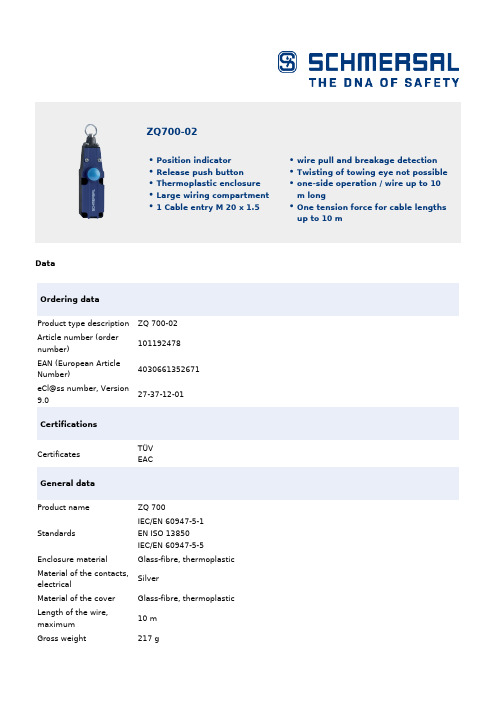
ZQ 700-02 产品说明说明书
DataOrdering dataProduct type descriptionZQ 700-02Article number (ordernumber)101192478EAN (European ArticleNumber)4030661352671eCl@ss number, Version9.027-37-12-01CertificationsCertificatesTÜV EAC General dataProduct nameZQ 700StandardsIEC/EN 60947-5-1 EN ISO 13850 IEC/EN 60947-5-5 Enclosure materialGlass-fibre, thermoplastic Material of the contacts,electricalSilver Material of the coverGlass-fibre, thermoplastic Length of the wire,maximum10 m Gross weight 217 g ZQ700-02Position indicatorRelease push buttonThermoplastic enclosureLarge wiring compartment1 Cable entry M 20 x 1.5wire pull and breakage detection Twisting of towing eye not possible one-side operation / wire up to 10 m long One tension force for cable lengthsup to 10 mGeneral data - FeaturesNumber of safety2contactsSafety appraisalStandards ISO 13849-1Mission Time20 Year(s)Safety appraisal - Safety outputsB10d Normally-closed100,000 Operationscontact (NC)Mechanical dataMechanical life, minimum1,000,000 OperationsMechanical data - Connection techniqueTerminal Connector Screw connectionCable section, minimum0.75 mm²Cable section, maximum 2.5 mm²Note (Cable section)All indications about the cable section are including the conductor ferrules. Mechanical data - DimensionsWidth40.5 mmHeight160 mmDepth50.9 mmAmbient conditionsProtection class IP 67 to IEC/EN 60529Ambient temperature,-25 °CminimumAmbient temperature,+70 °CmaximumRelative humidity,95 %maximumAmbient conditions - Insulation valueRated impulse withstand6 kVvoltageElectrical dataThermal test current10 AUtilisation category AC-15230 VACUtilisation category AC-154 AUtilisation category DC-1324 VDC Utilisation category DC-134 A Switching elementOpener (NC)Switching principle Snap switch elementNotesNote (General)Recommended cable lengths for pull-wire Emergency-Stop switches in relation tothe range of ambient temperature.As the thimbles are subject to deformation in case of wire pull, the wire should bepulled several times after fitting. After that, the wire must be re-tensioned using theeyebolt or the tensioner. At 2 m ... 5 m distance intermediate wire supports are required, see accessories Ordering codeProduct type description:ZQ 700-(1)-(2)(1)111 NO contacts/1 NC contact 02 2 NC contact(2)STM12 connector with A-coding PicturesProduct picture (catalogue individual photo)ID: kzq70f01| 180,8 kB | .jpg | 23.223 x 67.637 mm - 320 x 932Pixel - 350 dpi| 664,8 kB | .jpg | 240.947 x 702.028 mm - 683 x 1990Pixel - 72 dpi| 113,1 kB | .png | 74.083 x 215.547 mm - 210 x 611Pixel - 72 dpiDimensional drawing basic componentID: 1zq-7g01| 106,7 kB | .jpg | 352.778 x 245.181 mm - 1000 x 695Pixel - 72 dpi| 10,5 kB | .png | 74.083 x 51.506 mm - 210 x 146Pixel - 72 dpi| 198,7 kB | .cdr || 24,6 kB | .jpg | 112.889 x 78.317 mm - 320 x 222Pixel - 72 dpiDiagramID: ktf--k10| 19,2 kB | .jpg | 112.889 x 62.442 mm - 320 x 177Pixel - 72 dpi| 16,1 kB | .cdr |Characteristic curveID: kzq70d02| 25,3 kB | .jpg | 112.889 x 112.889 mm - 320 x 320Pixel - 72 dpi| 3,0 kB | .png | 74.083 x 74.083 mm - 210 x 210 Pixel- 72 dpiK.A. Schmersal GmbH & Co. KG, Möddinghofe 3, D-42279 WuppertalThe details and data referred to have been carefully checked. Images may diverge from original. Further technical data can be found in the manual. Technical amendments and errors possible.Generated on 08.07.2020 17:36:18。
QYCI515V100A车载智能充电机(水冷)

拆卸和报废处理注意事项
注意
本产品的包装箱可以重复使用,请小心拆开包装,并妥善保 存包装箱及包装材料,以便于产品调换及维修时再次使用。
产品报废后拆卸的金属器件可以回收再利用 部分器件会对环境造成不良影响,例如电解电容,请按照环
地址:北京市昌平区沙河镇昌平路 97 号新元科技 2 号楼 306 室(科技园区) 电话:010-60769937/38-802 传真:010-60769937-801
出
源调整率
负载调整率
DC515V DC100A 51.5KW ≤±0.3%(10%--100%负载) ≤±0.5%(额定电压输入,10%--100%负载)
效率
≥90%
输入欠压保护
具有
输入过压保护
具有
输出过压保护
具有
保 输出过流保护
护 过热保护值
功
能
短路保护
工作温度范围
湿度
具有 850C(可自动恢复,温度降至 600C 恢复工作)
2.1 安全注意事项
为了保证安全、可靠、合理的使用本产品,请在完全理解本手册所述的安全 注意事项后再使用该产品。
常规注意事项
警告 注意 重要
本产品带有危险电压,如果不遵守规定或不按本手册的要求 进行操作,可能会导致人身伤亡、产品或系统损坏。
只有经过培训的专业人员才允许操作本产品;正确的操作和 维护保养,是实现本产品安全稳定工作的可靠保证。
地址:北京市昌平区沙河镇昌平路 97 号新元科技 2 号楼 306 室(科技园区) 电话:010-60769937/38-802 传真:010-60769937-801
6
结构
体积重量
3.3 接线端口定义
Philips 7000 Series 用户手册说明书

变更语言
你可选择变更菜单的语言。 1 - 打开快速菜单,选择全部设置,进入设置菜单,选择 [通用设置] > [语言] > [菜单语言],然后按确认键。 2 - 选取你想要的语言后按 确认。
本产品含有开机推送广告且不可关闭,但广告播放过程中 按右键可以跳过。
1.2
像素特性
此液晶显示产品具有很高的彩色像素。 尽管其有效像素高达 99.999% 或更高,但屏幕仍可能持续 出现黑点或亮点(红色、绿色或蓝色)。 这是显示器的结构 属性(在通用行业标准之内),不是故障。
1.3
保修
用户不可更换任何组件。 请勿打开或取下电视机后盖暴露出产品内部。 必须由Philips 服务中心和官方修理店进行维修。否则所有 声明或暗示的保修都将失效。
(12) - 彩色按钮 多功能键。
(13) - 信号源 开启信号源选单,选择连接的设备。 (14) - 频道列表 显示频道列表。 (15) - 信息 提示当前电视所处的状态。 (16) - 应用选单 访问与当前活动或选择相关的选项。
(17) - 确认 确认输入或选择和在观看电视时显示频道列表。 (18) - 导航按钮
12 开源 23
12.1 开源软件 23 12.2 开源执照 23
2
1
公告
1.1
公告
2022 © Koninklijke Philips N.V 保留所有权利。
规格如有更改,恕不另行通知。 所有商标均是Koninklijke Philips N.V 或它们各自所有者的财产。TPV Display Technology (Xiamen) Co.,Ltd. 保留随时更改产品的权利 ,而且没有义务对较早前提供的产品进行相应的调整。
制造商:冠捷显示科技(厦门)有限公司 本手册中的材料对于此系统的设计用途来说已经足够。 如 果产品或其单个模块或程序用于除此处指定用途之外的其 它目的,则必须首先确认其有效性和适合性。
BOSCH CMS7000 说明书
CMS7000用户手册BOSCH Security systems Copyright 2001~2003目录CMS7000 ver 1.03 发布说明------------------------------------------------------2 CMS7000快速操作指南-----------------------------------------------------------3用户手册一 CMS7000安保系统简介--------------------------------9二 CMS7000安全系统的基本概念及术语-------------------11三 连接报警主机---------------------------------------15四 CMS7000安装---------------------------------------16五 CMS7000启动与操作员登录---------------------------18六 CMS7000参数设置-----------------------------------20七 CMS7000报警主机管理-------------------------------31八 CMS7000用户与防区管理-----------------------------33九 CMS7000报警监控与处理-----------------------------39十 CMS7000巡更管理-----------------------------------47 十一 CMS7000数据库安全与备份管理-----------------------52 十二 DS3/DS6MX支持-----------------------------------------------------55_______________________________ CMS7000 User Manual ______________________________ P/N 48426E © BOSCH Security SystemsCMS7000 1.03发布说明安装方法:直接使用光盘安装CMS7000 1.03注意:1.安装完成前不要安装USB类型的软件加密锁硬件.2.升级后原来在旧版本中中设置的参数将全部无效,必须升级后重新设置或从原备份数据中导入.用户组,用户和防区数据, 但不支持用户自己定义的防区类型新增功能1.更好的支持DS3MX和DS6MX2.新增CMS7000-10000支持最多 10000用户,30000防区.3.支持门禁系统 BOSCH_VDP_A300 和 HCS3300,HCS3500,HC3220.4.系统参数允许选择实时打印输出是否有效,默认值为不进行实时打印.5.从备份的早期版本的数据库中导入户组,用户与防区参数, 但不支持用户自己定义的防区类型数据.6.允许在登录管理中修改当前操作员口令_______________________________ CMS7000 User Manual ______________________________ P/N 48426E © BOSCH Security SystemsCMS7000快速指南1. 硬件安装指南:接线方法:参数设置:如果使用v4.05版的BIOS程序,设置如下相关参数编程地址4019,值为18。
Philips Series 7000 电动刮头机说明说明书

S7782/50de près, protection cutanée avancée la technologie SkinIQLe rasoir Philips Series 7000 glisse parfaitement sur la peau et coupe chaque poil de près, même lorsque vous rasez une barbe de 3 jours. Grâceàsa technologie avancée SkinIQ, ce rasoir est capable de détecter, de s'adapter et de guider vos gestes, pour une meilleure protection cutanée.Rasage de très prèsSuit les contours de votre visageDes performances amélioréesàchaque passageGuide les poils pour leur donner une position de coupe optimaleTechnologie SkinIQVous guide pour vous permettre d'améliorer votre technique de rasageMaîtrisez votre technique avec l'application Philips GroomTribeUn rasoir puissant pour dompter les barbesUn rasoir qui réduit les frottements pour minimiser les irritationsPour un rasage pratiqueSélectionnez un rasage pratiqueàsec ou rafraîchissant sur peau humideÉgalisez votre moustache et vos pattes60 minutes de rasage pour 1 h de chargeStation de nettoyage pour l'entretien de votre rasoir et l'hygièneCharge complète en une heurePoints fortsRevêtement protecteurSkinGlideUn revêtement protecteur sépare les têtes de rasage de votre peau . Contenant jusqu 'à2 000 microbilles par millimètre carré, il réduit les frottements sur la peau de 25 %* pour minimiser les irritations .LamesSteelPrecisionPuissantes et respectueuses de la peau , les 45 lames auto -a ffûtées SteelPrecision de ce rasoir Philips peuvent e ffectuer jusqu 'à90 000 coupes par minute pour plus de poils coupés par passage **, et une finition nette et confortable .Capteur MotionControlLa technologie de détection des mouvements de ce rasoir électrique surveille votre rasage et vous guide pour vous permettre d 'acquérir une technique plus e fficace . A près seulement trois rasages , la majorité des hommes ont amélioréleur technique de rasage et réduit le nombre de passages ***.Personnalisation via l 'applicationConnectez votre rasoir électrique Philips àl 'application GroomTribe pour avoir un suivi personnalisé. Vous pourrez suivre vos progrès et personnaliser vos gestes pour obtenir un rasage de près respectueux de la peau .Capteur Power AdaptCe rasoir électrique est équipé d 'un capteur intelligent de pilosité faciale qui détecte la densité des poils 125 fois par seconde . Cette technologie ajuste automatiquement la puissance de coupe pour vous procurer un rasage en douceur et sans e ffort .Têtes flexibles 360-DConçu pour suivre les contours de votre visage ,ce rasoir électrique Philips est doté de têtes entièrement flexibles qui pivotent à 360° pour un rasage impeccable et confortable .Têtes de précision Hair -GuideCe nouveau rasoir de stylisation de précision est doté de canaux de guidage des poils pour une coupe et un confort optimaux .Quick Clean Pod sanscâble10 fois plus e fficace qu 'un nettoyage àl 'eau ****, le puissant module de nettoyage nettoie et lubri fie votre rasoir en 1 minuteseulement . Son utilisation permet de maintenir les performances du rasoir et d 'améliorer l 'hygiène .Rasage sur peau humide ousècheUn rasoir 100 % étanche qui s 'adapte à vos préférences . Optez pour un rasage à sec pratique ou utilisez votre mousse ou gelpréféré pour un rasage rafraîchissant sur peau humide .CaractéristiquesA ccessoiresEntretien: Brossette de nettoyageQuick Clean Pod: 1 cartouche incluse, Oui Tondeuse rétractable intégréeVoyage et rangement: Housse de voyage LogicielsA pplication: GroomTribe, Connexion Bluetooth®Miseàjour du logiciel: Philips offre des mises àjour de logiciels pendant une période de deux ans après la date d'achat. Compatibilitédes smartphones: iPhone etA ndroid™A limentationTension automatique: 100-240 VCharge: Charge complète en 1 heure, Recharge rapide en 5 min Type de batterie: Li-ionA utonomie: 60 minutesConsommation en veille: 0,04 WConsommation maximale: 9 WDesignCouleur: Bleu nuitManche: Poignée antidérapanteTêtes de rasoir: A ngulairesEntretienGarantie de 2 ansTête de rechange: Remplacer tous les 2 ansavec SH71Performance de rasageSystème de rasage: Lames SteelPrecisionSkinComfort: SkinGlideSuivi des contours: Têtes flexibles 360-DTechnologie SkinIQ: Revêtement protecteurSkinGlide, Capteur Motion Control, CapteurPower A daptFacile d’utilisationÀsec ou avec de la mousse: Utilisableàsec ouavec de la mousseAfficheur: Indicateur Motion Control, AffichageLED, Voyant de niveau de chargeNettoyage: Ouverture d'une simple pression,Entièrement lavableSmartClickA daptéaux types de produits: Le produitRQ585/51 NE s’adapte P A S au type de têteangulaire* par rapport aux matériaux sans revêtement* * Tests comparatifs avec le Philips Series 3000.* * * Basésur les utilisateurs du Philips Series S7000 et del'application GroomTribe en 2019.* * * * Comparaison des débris de rasage après utilisationdu liquide de nettoyage par rapportàde l'eau dans lacartouche© 2023 Koninklijke Philips N.V. Tous droits réservés.Les caractéristiques sont sujettesàmodification sans préavis. Les marques commerciales sont la propriétéde Koninklijke Philips N.V. ou de leurs détenteurs respectifs.Date de publication 2023‑08‑12 Version: 12.12.1E A N: 87 10103 93933 7 。
Philips 7000系列无线洗净器说明书

Bagless vacuum cleaner900 WPowerCyclone 8Allergy LockOn board accessoriesFC9743Highest suction powerwith PowerCyclone 8*The Philips Bagless Vacuum 7000 Series features our highest ever suction power. Makesupreme cleaning effortlessly simple with PowerCyclone 8 technology and TriActive+nozzle featuring 3 optimized cleaning actions in one.Superior performance•900W motor for high suction power•99.9% dust pick-up*** to deliver high cleaning performance•Allergy Lock traps dust inside for a high level of hygiene•PowerCyclone 8 enables highest suction power for longer•TriActive+ nozzle to deliver high performance on all floors•CarpetClean nozzle slides easy for a deep carpet cleaning•Allergy H13 filter system captures >99.9% of fine dustEffortless cleaning•On board accessories: Conveniently stored, always at hand•Digital power control function to adjust suction power•Dust container designed for hygienic emptying with one hand•Soft brush integrated into handle, always ready to useHighlightsHigh-efficiency 900W motorHigh-efficiency 900W motor with over 50,000 RPM, generates high suction power for a superior clean every time. Register at within 3 months of purchase for a 5-year motor warranty.99.9% dust pick-up***TriActive+ nozzle and extreme suction power ensure you can vacuum 99.9% of fine dust***.PowerCyclone 8 technologyPowerCyclone 8 technology features apowerful, swirling action to maximize air flow and enable highest suction power. Superaccelerated air flow in the cylindrical chamber efficiently separates dust from the air at >185km/h, ensuring stronger suction power for longer, for immaculate cleaning results.Allergy lock Allergy Lock system uses a sensor to ensure dust container is fully sealed before operating, trapping dust and allergens inside for a clean and ultra hygienic environment.TriActive+ nozzleTriActive+ nozzle utilizes 3 cleaning actions in one go. It features a larger opening at the front to suck up larger debris while the specially designed soleplate removes dust from deep within carpets. Air channels and brushes on both sides of the nozzle pick up any dust and dirt alongside walls or furniture.On board accessoriesOnboard accessories are stored conveniently inside the back compartment so they're always easy to access when you need them.Digital power controlDigital power control function easily adjusts suction power for different cleaning tasks, from hard floors to soft furnishings, with the touch of a button.Hygienic dust disposalEasy-to-empty dust container is designed for hygienic disposal with one hand to help minimize dust cloud.Integrated brushDusting brush tool is built into the handle so it's always ready to use on furniture, flat surfaces and upholstery.Issue date 2021-01-23 Version: 0.0.112 NC: 0000 041 02555 EAN: 87 10895 69046 1© 2021 Koninklijke Philips N.V.All Rights reserved.Specifications are subject to change without notice. Trademarks are the property of Koninklijke Philips N.V. or their respective owners.SpecificationsPerformance•Airflow (max): 32,5 l/s•Input power (max): 900 W•Sound power level: 67 – 75 dBNozzles and accessories•Accessory storage: On board•Standard nozzle: TriActive+ nozzle •Accessories included: Crevice tool, Integrated brush, Small nozzle•Additional nozzle: Carpet Clean nozzle, Hard floor nozzle•Extra accessories: Filter replacement: FC8003/01 Design•Color: Louros BlueFiltration•Dust capacity: 2 L•Exhaust filter: Allergy H13 filter •Motor filter: Lifetime washable filter•Filtration level: HEPA13 level****Sustainability•Packaging: > 90% recycled materials•Stand-by power consumption: < 0,5 W•User manual: 100% recycled paperUsability•Action radius: 10 m•Carrying handle: Top and front•Cord length:7 m•Power control: Electronic on appliance•Tube coupling: SmartLock•Tube type: Metal 2-piece telescopic tube•Wheel type: RubberWeight and dimensions•Dimensions of product (LxWxH):505x292x292 mm•Weight of product: 5.5 kg*suction power compared to 10 most selling high end bagless vacuumcleaners (> 150€) in Germany H1’2019**Filtration performance is tested to DIN EN 60312/11/2008.***99.9% dust pick-up on hard floors with crevices (IEC62885-2).****Filtration levels are tested according EN60312-1-2017 and areequivalent to HEPA 13.。
870说明书
技术说明书 (R1 版 Ver 1.00)
许继电气股份有限公司 XJ ELECTRIC CO.,LTD.
W**-872 微机保护测控装置
目录
1 概述.........................................................................................................................................................1 1.1 应用范围............................................................................................................................................. 1 1.2 产品特点............................................................................................................................................. 1 1.3 保护配置............................................................................................................................................. 1 2 技术指标 ..................................................................................
ZH07系列传感器说明书
1500
2000 Φ55 Φ125 168 385 105 161
74
72
82
8.5 198 16 2500 16×100×10×4
2500
3000 Φ65 Φ132 165 385 105 172
80
72
82
8.5 198 18 2500 18×103×11×4
5000
7000 Φ75 Φ146 180 396 105 186
正向
转矩测量计算式
N
Mp=N (f-f0) / (fp-f0)
fr
0
f0 fp
Mr=N (f0-f) / (f0-fr)
-N
负向
Mp:正向转矩 N:转矩满量程 fP:正向满量程输出频率值(kHz) f:实测转矩输出频率值(kHz)
Mr:反向转矩 f0:转矩零点输出频率值(kHz) fr:反向满量程输出频率值(kHz)
8 6.5 63 127 62 10000~21000 8×40×7×2
300 Φ28 Φ90 242 42
152 72
8 6.5 63 130 62 8500~18000
8×40×7×2
500 Φ38 Φ100 272 56
154 72 2-10 6.5
69 140 62
7000~13000
10×54×8×4
能造成弹性轴永久变形,无法回到测量零点。
8
⌦ 传感器与仪表的连接
转矩转速测量仪
1. 确保仪表电源关断。 2. 连接测试电缆线(按附图)。 3. 打开仪表电源开关即可工作(进入测量状态)。
附图 注:仪表使用请详细阅读 ZHK-D 转矩转速测量仪使用说明书。
特别注意
比亚迪秦2015款双冠旗舰版说明书

比亚迪秦2015款双冠旗舰版说明书比亚迪秦2015款双冠旗舰版是比亚迪秦真正意义上量产的一款纯电动汽车,在去年9月份就已全球销量突破6.6万辆。
3很多领域的技术都为比亚迪秦后续的电动汽车开发做了充实的积累和探索,比如整车的轻量化技术、电池系统的模块化技术、热管理技术等。
从动力电池系统角度来看,3自2013年11月份上市以来,共进行了一次升级,即在2016年电量由22kWh,提升为33kWh,电量提高50%,这一次升级,保持了电池包体积、结构不变。
于16年升级之前的3,续航里程在81英里/130公里(33度电的在114英里/183公里),电池包总电量为22kWh,容量60Ah,总电压353V;电池包的总重量约为235kg,比能为93.6Wh/kg(33度电的比能约为140.4Wh/kg)。
比亚迪秦3一直使用的电芯是方形铝壳,NCM,由三星SDI提供,额定电压在3.7V,电压限值区间为2.8-4.1VDC,电芯的比能在120Wh/kg以上,电芯的内阻在0.5 mΩ左右。
3电池包共有8个模组组成,每个模组有12个电芯,共计96个电芯,串联。
关于94Ah电芯的数据尚没有官方的公布,不过,从ev-power.eu上第三方供应商的信息可以了解到:额定电压:3.7V,电压区间2.75V-4.15V推荐的充电/放电电流0.33 C(31A)循环寿命:80%的深放电循环3200个周期,剩余容量还高达80%的(在94安放电电流下)最大的放电电流是连续1C和峰值4.3C(413A最大的充电电流是连续0.5C尺寸大小:173*125*45mm电芯重量:2kg充电温度范围:0°C ~ 60°C放电温度范围:-25°C ~ 60°C3的电连接,高压线束(科士达Kostal提供)采用插接式与模组连接,与电极间的连接则通过超声焊实现,采样线先超声焊再点胶的方式与连接片相连。
比亚迪秦3的热管理采用直冷方案(也有液冷方案),制冷剂为R134a,制冷剂的进出走向见下图(根据已有信息推断,未经官方证实)。
北石70顶驱操作手册

对于随机文件中没有涉及的内容,以及安装、使用和维护中的其他问题, 如果需要,请与制造厂联系:
电 话: 传 真: 电子邮件: 地 址: 邮政编码:
010-62097381 010-62097613 bpm.zhaojing@ 北京市 海淀区 志新路 41 号 100083
目
录
1 2 2.1 2.2 2.3 3 3.1 3.2 3.3 3.4 3.5 3.6 3.7 3.8 3.9 4 4.1 4.1.1 4.1.2 4.1.3 4.1.4 4.1.5 4.1.6 4.2 4.2.1 4.2.2
4.2.5 背钳 ......................................................................................................................18
4.2.6 丝扣防松机构 .......................................................................................................21
顶部驱动钻井装置
操作手册
型号: DQ70BSC
Serial No: 06032
前言
本产品的设计、制造和服务依据以下质量保证体系:
GB/T19001:2000 idt ISO9001:2000《质量保证体系》
API Spec Q1《石油与天然气工业质量程序规范》
本手册包含与顶驱操作、使用和维修有关的技术信息。关于本产品的其他 技术性说明分别包含在以下文件中:
4.2.3 遥控内防喷器控制机构........................................................................................17
ZQ 700-02紧急停止开关说明书

Datasheet - ZQ 700-02Pull-wire emergency stop switches / ZQ 700Preferred typ(Minor differences between the printed image and the originalproduct may exist!) • thermoplastic enclosure• one-side operation / wire up to 10 m long• Release push button• Position indicator• Large wiring compartment• Twisting of towing eye not possible• wire pull and breakage detection• One tension force for cable lengths up to 10 m • 1 Cable entry M 20 x 1.5Ordering detailsProduct type description ZQ 700-02Article number 1192478EAN code 4030661352671 ApprovalApprovalTÜVUSA/CANCCC ClassificationStandards EN ISO 13849-1B10d Opener (NC) 100.000Mission time 20 YearsnoticeGlobal PropertiesProduct name ZQ 700Standards EN 60947-5-1, IEC/EN 60947-5-5, EN ISO 13850Compliance with the Directives (Y/N) YesMaterialsthermoplastic- Material of the housings Plastic,- Material of the cover Plastic, thermoplastic- Material of the contacts Silverg Weight 216 Emergency-Stop button (Y/N) NoMechanical dataDesign of electrical connection Screw connectionCable section- Min. Cable section 0,75 mm²- Max. Cable section 2.5 mm²Mechanical life > 1.000.000 operationsLength of wire max. 10 mnotice All indications about the cable section are including theconductor ferrules.Ambient conditionsAmbient temperature- Min. environmental temperature −25 °C- Max. environmental temperature +70 °CProtection class IP67 to IEC/EN 60529Electrical dataDesign of control element Opener (NC)Switching principle Snap switch elementNumber of auxiliary contacts 0 pieceNumber of safety contacts 2 piecekVRated impulse withstand voltage U imp 6VRated insulation voltage U i 500AThermal test current I the 10Utilisation category AC-15: 230 V / 4 A,DC-13: 24 V / 4 AMax. fuse rating 6 A gG D-fuseDimensionsDimensions- Width 40.5 mm- Height 160 mm- Depth 50.9 mmnoticeAt 2 bis 5 m distance intermediate wire supports are required, see accessoriesRecommended cable lengths for pull-wire Emergency-Stop switches in relation to the range of ambient temperature. As the thimbles are subject to deformation in case of wire pull, the wire should be pulled several times after fitting. After that, the wire must be re-tensioned using the eyebolt or the tensioner.Indication legend1 = Wire rope2 = Eyeboltnut 3 =4 = Wire clamp5 = Tensioning jackWire thimble 6 =shackle 7 =8 = rope tensionerA = Position indicatorB = reset buttonDiagramNote Diagrampositive break NC contactactiveno activeNormally-open contactNormally-closed contactOrdering codeZQ 700-(1)(1)111 Normally open contact (NO) / 1 Opener (NC)022 Opener (NC)Dimensional drawing (basic component)Characteristic curveApplicationApplicationApplicationSystem componentsAccessories1162986 - Eyebolt BM 8 x 701192471 - Eyebolt BM 8 x 70 NIRO1084928 - Eyebolt BM 10 x 401203477 - Wire clamp 3 mm NIRO1203569 - Wire clamp 4 mm NIRO1203478 - Wire clamp 5 mm NIRO1190917 - Duplex wire clamp 3 mm NIRO • for Wire rope Ø 3 mm1203569 - Duplex wire clamp 4 mm NIRO • for Wire rope Ø 3 mm1196043 - Egg-shaped wire clamp GR 3• for Wire rope Ø 3 mm1077072 - Egg-shaped wire clamp GR 4• for Wire rope Ø 4 mm1203472 - WIRE THIMBLE 3 mm NIRO• for Wire rope Ø 3 mm• to DIN 68991170750 - WIRE THIMBLE 4 mm• for Wire rope Ø 4 mm• to DIN 68991203475 - WIRE THIMBLE 4 mm NIRO• for Wire rope Ø 4 mm• to DIN 68991203476 - WIRE THIMBLE 5 mm NIRO• for Wire rope Ø 5 mm• to DIN 68991192433 - PULLEY• for Wire rope Ø 3 mm• To guide the wire rope where the path is not a straightline1087930 - TENSIONING JACK M6• For exact adjustment of the tension of the wire rope • to DIN 14801186696 - TENSION SPRING RZ-2041• To maintain the reaction forcePag1087931 - TENSION SPRING RZ-136E• To maintain the reaction force1170752 - TENSION SPRING RZ-156I• To maintain the reaction force1186490 - SHACKLE NIRO• Shackle for fixing the wire rope to the eyebolt1122315 - TENSION SPRING RZ-172• To maintain the reaction force1094517 - WIRE ROPE 5 mm• With red PVC sheath• Ø 5 mm total• Steel core Ø 3 mm1147304 - WIRE UNIT COMPLETE 5 m• Ready-to-fit• With red PVC sheath1155097 - WIRE UNIT COMPLETE 10 m• Ready-to-fit• With red PVC sheath1186704 - rope tensioner S 900• Smooth adjustment• Only one tool• Antiskid• Time-saving• Ergonomic• No risk of injuryK.A. Schmersal GmbH, Möddinghofe 30, D-42279 WuppertalThe data and values have been checked throroughly. Technical modifications and errors excepted.Generiert am 28.09.2011 - 15:16:27h Kasbase 1.5.5 DBI/datenblatt?lang=en&produkt=eq6733105bdc92l4pv440539...28/09/2011。
太阳能水泵7000系列用户手册说明书

The Dankoff SunCentric ™ uses solar-electricpower to pump as much as 50,000 gallons (200 cu. m.) per day from shallow water sources.Applications include irrigation, livestock, domestic water, pond management, water treatment, solar water heating, hydronic space heating, fireprotection, and more. These pumps have been in worldwide use since 1989. They can be used without batteries. Maximum suction lift is 10vertical feet (3 m).PV Array-Direct Application• A PV-direct system uses water storage instead of batteries.This is the simplest and most durable system for most applications.• A pump controller (linear current booster) is NOT required.• A solar tracker (optional) will help to maintain optimum flow through the entire solar day.• Storage of 3-7 days’ water demand is recommended.• Optimum for circulation of solar-heated waterBattery Application• A battery system is best where there is need for constant pressure or pressure on demand, or where a tank is not feasible, or where a battery system is required for other power applications.• Batteries can be charged by any power source.Selecting a Pump• Select the appropriate chart of “PV Array-Direct Applications” or “Battery Applications”.• Total Dynamic Head = Vertical distance from surface of the water source to the discharge or top of storage tank + pipe friction losses.• Use the solid line grid for English units. Use broken line grid for metric units.• Locate the coordinates for the required head and flow.• Find the pump curve that is nearest to that point.• If there is more than one curve to chose from, compare the power requirements. If PV-direct, the curve that goes higher will work better during low sun intensity.• For PV-Direct systems, array size (watts) is critical. DO NOT undersize the array. Oversizing will improve performance in low sunlight conditions.• Multiple pumps can be used to provide greater flow.Suction Capacity• Suction limit is 10 vertical feet (3 m) at sea level–subtract 1 foot for every 1000 ft. elevation (1 m per km).• For best reliability, minimize or eliminate suction lift by placing the pump low and close to the water source. This will minimize the possibility of cavitation which causes excessive wear and loss of performance.Pump Installation• Pump must be sheltered from rain and direct sunlight.• Horizontal position: Place outlet at the top. It can be rotated to face horizontally or vertically upward.• Vertical position: Place motor on top.Wire and Pipe Requirements• Intake pipe: Pipe should be as direct and short as possible. Avoid any high point that can trap an air pocket.• Refer to a pipe sizing chart (included with the pump instructions). Pipe may need to be larger than the pump ports. Undersized pipe will greatly decrease pump performance.• Size the wire for less than 3% voltage drop. Undersized wire will greatly decrease pump performance. Refer to a low voltage wire sizing chart (available from Dankoff Solar). Overcurrent Protection• Fuse or circuit breaker is required.• Ampere rating = amps at the pump + 15-25%• Minimum DC voltage rating = volts at the pump X 2. (Type FRN fuses are rated 125V DC)Maintenance• No routine maintenance is required.• Pump can be repaired in the field using ordinary tools and skills, without removing the pipes.• Instruction manual shows illustrated repair details.• Motor brushes: Typical brush life peak hours = working voltage X 800 / 3rd digit of model number. EXAMPLE: PV-Direct curve #60 is Model 7526 working at 30V. Typical brush life = 30 X 800 / 2 = 12,000 peak hours. This represents about 5-8 years of service.• Shaft seal has a very long life under normal conditions. Purchase spare seals if water is loaded with abrasive silt or if pump can possibly run dry.Version 2.2a July 2003Typical model shown here.Proportions and electrical connections vary.Materials• Pump body: cast iron, ASTM A48-76• Impeller: glass filled polycarbonate• Seal: carbon/ceramic, industry standard • Temperature limit: 140°F (60°C)High Temperature Option• Temperature limit: 240°F (115°C)• Impeller: brass• Brass impeller reduces flow by about 15% (same watts)• Order standard pump +"High Temp Option" Item #38275Accessories• Foot Valve (for pump placed higher than water source)• Float switches: please inquire• Basket Strainer: Swimming pool type, fits on pump inlet, catches debris and allows easy cleanout. 1 1/4" in/out, Item #37685Spare Parts• Seal & Gasket Kit: specify pump number, and if high temperature• Motor Brush Kits: specify model number Warranty• Two years against defects in materials and workmanship.Version 2.2a July 2003。
ZTSD7000 售电软件使用说明书要点

4.5.1.1开户卡
首先进入档案管理界面,选择需要制作开户卡(初始化卡)的用户档案,在档案界面上单击“制作开户卡”按钮,进入开户卡操作界面;如下图所示:
图42开户卡(初始化卡)操作
操作步骤:
1)确定卡的类型是否为空卡或新卡,如果不是则首先进行擦卡操作。
2)进入档案管理,选择需要进行初始化的用户,单击“初始化”按钮。
端口号,IC卡读写器首次接入电脑,需要安装卡机驱动(卡机驱动文件,由正泰公司提供)。驱动安装成功后,会有一个通讯端口号。这里输入该端口号即可。
系统号,正确往IC卡读写器中插入系统设置卡(正泰公司提供),点击“获取”,读取系统号。
区域号,由注册人员手动输入,区域号由数字组成。
图37系统注册工具
3.
本系统在功能上分为:用户管理、IC卡操作、电量查询、统计报表、系统维护等五大模块。
2.
2.1
本软件配有安装光盘,运行安装光盘中的ZTSD7000售电系统.EXE,根据提示操作,安装程序会自动进行软件安装,如果使用网络版售电系统,需要安装Sqlserver2000数据库。SQL Server数据库安装是针对网络版售电系统而言的,单机版不需要进行这一步安装。该项操作需要计算机安装“数据库SQL Server2000”,如果计算机已经安装此软件,请跳过“SQLSERVER服务器的安装”,若该计算机没有安装“数据库SQL Server2000”,参照下面步骤安装本软件。
图40档案管理
4.3.1建立用户档案
1)单击增加按钮激活各操作文本框。
2)输入用户名称、用户编号、电表编号、用户地址、建立日期、证件代码、联系电话。
3)单击保存按钮即完成添加用户基本资料的录入工作。
说明:按照一表一卡的对应关系,电表编号和用户编号两者都不能重复;如果用户编号或电表编号有重复,则系统有告警提示,不允许增加该用户档案。
-7000P系列使用说明书
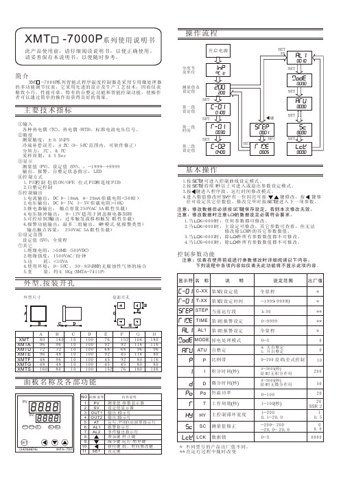
基本操作 1.按SET键可进入控制曲线设定模式。
键持续3秒以上可进入或退出参数设定模式。
SV中有一位闪亮可按 键修改,按 键移 位可设定其它位数值,修改完毕时按注意:修改数据后必须按SET键保存设定,否则本次修改无效。
注意:修改数据时注意LCK的数据设定必需符合要求。
1.当LCK=0000时,任何参数都可修改。
2.当LCK=0001时,主设定可修改,其它参数可查看,但无法 修改除LCK外的其它参数数值。
3.当LCK=0002时,除LCK外所有参数数值都不可修改。
4.当LCK=0003时,除LCK外所有参数数值都不可修改。
分度号及单位测量值及设定值第一段设定值第一段时间第二段设定值操作流程主要技术指标XMT -7000P系列使用说明书此产品使用前,请仔细阅读说明书,以便正确使用。
请妥善保存本说明书,以便随时参考。
①输入 各种热电偶(TC)、热电偶(RTD)、标准电流电压信号。
②精度 测量精度:0.5%FS 冷端补偿误差:0~50范围内,可软件修正) 分辩力:1 采样周期:0.5 Sec③显示 测量值(PV)、设定值(SV)、:-1999~+9999 输出、报警、自整定状态指示:LED④控制方式 1.PID控制(包括ON/OFF,位式PID和连续PID) 2.自整定控制⑤控制输出 1.电流输出:DC 0~10mA,4~20mA(负载电阻<500) 2.电压输出:DC 0~5V,1~5V(负载电阻>10K) 3.继电器输出: 触点容量250VAC 3A(阻性负载) 4.电压脉冲输出: 0~12V(适用于固态继电器SSR) 5.可控硅SCR输出:过零触发或移相触发(阻性负载) 6.报警功能输出:最多二组输出,6种模式(见报警类型) 输出触点容量: 250VAC 3A(阻性负载)⑥设定范围 设定值(SV):全量程⑦其它 1.绝缘电阻:>50M(500VDC) 2.绝缘强度:1500VAC/1分钟 3.功 耗:<10VA 4.使用环境:0~50,30~85%RH的无腐蚀性气体的场合 5.重 量:约0.5Kg(XMTA-7411P)±±2℃(℃℃、0.1℃ΩΩ℃A48481010101010101010010010010010010010045458080489645928011672726868969696489245116809680160961608092761529215276116106180116180106XMTGXMTFXMTDXMTEXMTAXMTXMTSBCDEFGH外型.按装开孔BDC盘面开孔外型尺寸简介 XMT -7000P系列智能式程序温度控制器是采用专用微处理器的多功能调节仪表,它采用先进的设计及生产工艺技术,因而仪表精致小巧,性能可靠。
BC-7000电池容量测试仪操作手册说明书
1BC BC--7000CAPACITY TESTEROPERATIONS MANUALCOFKO LLC.COPYRIGHT © 2013To buy, sell, rent or trade-in this product please click on the link below:https:///Power-Products-BC-7000-Battery-Charger.aspxUNPACKINGAs you unpack your new BC-7000 battery capacity tester, inspect the tester for signs of shipping damage. If shipping damage is present, stop and contact the shipping company for damage claims information. The box should contain the BC-7000 tester, operators instruction manual, AC power cord, USB cable, battery disconnect (7017-2), 2 battery adapter cables, and BC Report software.IMPORTANT: Save the shipping box and packaging material. They should be used to repack the tester if it needs to be shipped back for warranty or service.2INTRODUCTIONCongratulations on acquiring your new BC-7000 battery capacity tester. The BC-7000 battery capacity tester has been designed to provide the operator with accurate battery capacity testing and ease of operation.The features of the BC-7000 are:- Adjustable constant current load in 0.1 Ampere increments from 0.5 Ampere to 15 Ampere.- Adjustable constant current load in 1.0 Ampere increments from 15 Ampere to 55 Ampere.- Universal AC power input 85~264Vac 1 PH (47 to 63Hz)- LCD display.- 10mv voltage resolution.- Over temperature protection.- Audio warning when capacity test is complete or malfunction of the unit.- USB 2.0 port for PC connection.- Windows TM XP or Higher compatible BC Report Utility software for test data hardcopy print out.- Real time internal clock with battery backup.- 1 year warranty.Before operating your new BC-7000 battery capacity tester, familiarize yourself with this operators manual and the unit.Questions?Call: (909) 705-6267 Mon.-Fri.8:00 A.M. to 5:00 P.M. PST or *****************Thank you,COFKOManual: BC-7000Revision: C Date: 04/05/133CONTENTS PAGEBC-8000 History of Revisions (5)BC-7000 SAFETY NOTES ………………………………………………………………….…….................................................… 6,7BC REPORT UTILITY AND REAL TIME CLOCK SETUP (8)BC-7000 OPERATION …………………………………………......................................................................…....……. 9,10,11BC-7000 REPORT PRINTING (11)BC-7000 CARE (12)BC-7000 TECHNICAL DATA ……………………………………………………………………………......................…..................….. 13,14BC-7000 LIMITED WARRANTY (15)BC-7000 NOTES (16)BC-7000 CERTIFCATION OF FACTORY CALIBRATION (17)4History of RevisionsRevision #Effective Date Description of Change Approval ByA11/11/2010Initial issue M.C.B10/23/2012Increase Maximum Operation Altitude from 6000’ to 6500’ M.CB10/23/2012Change Description of Box Contents M.C.C04/05/2013Minimum and Maximum Operation Temperature M.C.56SAFETY NOTESYour new BC-7000 battery capacity tester has been designed with operator safety as a function of its design,construction, and operation. Understanding how to safely operate the BC-7000 battery capacity tester is important. Failure to follow the operation and safety guidelines when using the BC-7000 can result in personal injury to the operator and damage to the BC-7000. Always review the battery manufacturer’s battery capacity testing guidelinesbefore testing batteries.Look for this symbol to identify Safety and Danger precautions. Be Alert- Your safety isinvolved! Personal injury or equipment damage can occur if guidelines are not followed. PRECAUTIONS:Precautions:1 CAUTION: Aircraft batteries are certified to have a certain minimum capacity for emergency operations inthe event of an electrical generator system failure. Never “jump start” an aircraft that has a discharged or“dead” battery.2 WARNING: ELECTRIC SHOCK HAZARD. Do not touch un-insulated portions of the connector or the batteryterminals. A possibility of serious electrical shock exists. Do not lay tools or other metal objects on thebattery as arcing or explosion could occur. Remove conductive jewelry before working around battery,charger, or test equipment.3 CAUTION: ELECTRIC BURN HAZARD. Do not wear conductive rings, belt buckles, or other jewelry whenworking with batteries, chargers, or test equipment. Do not lay tools or other metal objects on the batteryas arcing and severe burns could occur.4 WARNING: Batteries on charge or discharge produce hydrogen gas, which can explode if ignited. Do notsmoke, use an open flame, or cause sparking near a battery. Charge, service or test a battery only in a wellventilated area. The use of exhaust fans may reduce the risk of explosion.5 WARNING: Batteries contain sulfuric acid which will cause burns . DO NOT TOUCH EYES AFTER TOUCHINGBATTERY . Do not get acid in your eyes, or on your skin, or clothing. In the event of acid in the eyes, flushthoroughly with clean cool water for several minutes. Get professional medical attention. Refer to batteryMSDS for additional information.6 WARNING: Wear proper eye, face and hand protection at all times when working with batteries. Know thelocation and use of emergency eyewash and shower nearest the battery charging area.7 CAUTION: To prevent damage to the connector, arc burns, or explosion, batteries should never beconnected or disconnected while being charged or discharged. Batteries must be connected or disconnected only when the circuit is open. Ensure the aircraft battery switch, external power source, or thecharger/analyzer is in the “OFF” position before connecting or disconnecting the battery. Battery terminal protectors should be installed whenever the battery is not connected in the aircraft or to the testequipment.8 CAUTION: Batteries contain hazardous materials. Know the location and proper use of emergency responsematerials. Refer to battery Material Safety Data Sheet (MSDS) for additional information.9 Caution / Warning: Only constant potential charging may be done on the aircraft. DO NOT constant currentcharge a battery on the aircraft. There could be a serious risk of injury to personnel and / or damage to the aircraft or aircraft systems due to high voltage and generation of explosive gases when charging constant current.10 DANGER: Never connect or disconnect BC-7000 tester main power connector with the switch on. Connectingor disconnecting the BC-7000 tester with discharge current applied can cause a spark and possible battery explosion.11 DANGER: Never capacity test batteries without first inspecting all battery wires and connection for conditionand tightness. Replace all defective wires and bad connections before capacity testing batteries. Defective wiring and bad connections can cause overheating during a capacity test.12 DANGER: never connect the BC-7000 capacity tester to batteries with voltage or capacity currents outsidethe ratings of the tester. The BC-7000 tester is designed for 12 and 24 volt batteries. Connecting the tester to batteries with different voltages can permanently damage the tester and endanger the operator. Anyquestionsthatariseaboutthebatteryortesterratings,**********************13 DANGER: never obstruct the BC-7000 tester air intake or hot air exhaust openings. Obstructing eitheropening can cause the tester to overheat.7BC Report Utility and Real Time Clock SetupNOTE: The BC Report Utility software MUST be installed on the computer used to connect to the BC-7000 tester first. Do not connect the USB communication cable to the BC-7000 until this is done.1 Remove the BC Report Utility CD from the protective sleeve and place disk into the PC CD drive. The BC Report Utility will automatically start installing. (Manual installation can be done with commands: Start\Run\ d:\setup.exe2 Windows Application Security Warning dialog box may prompt you about installing the BC Report Utility. To continue installing the BC Report Utility, click on the INSTALL button. The installation may take some time as Windows TM installs all the necessary software.3 When prompted to install the Silicon Labs CP210x USB to UART bridge driver, click the INSTALL button to install all needed drivers. (C:\Program Files\Silabs\MCU\CP210x\) Note: The CP210x drivers are on the BC Report Utility CD disk.4 After the BC Report Utility software installation is completed, remove the BC Report Utility CD disk from the drive and return to the protective sleeve. Now restart the PC .5 The Windows TM desktop should now contain the BC Report Utility program icon. Plug the USB cable supplied with the BC-7000 into a working USB port on the PC with the BC Report Utility installed. Connect the AC power cord to the BC-7000 and set the power switch to the ON position. Now plug the remaining USB cable end into the USB port located on the right side rear of the BC-7000. If the connection is made between the PC and the BC-7000 the PC may respond with an audio sound confirming a device has been found.6 To run the BC Report Utility, place the mouse pointer on the icon and press the left mouse button. This action will start the BC Report Utility program and display the program window.7 Before updating the BC-7000 internal date and clock, check the computer date and time for proper setting and adjust if needed. This is the date and time the BC-7000 will use. Located in the lower middle of the BC-7000 Report window is the SET Date & Time button. To set the BC-7000 Date & Time place the mouse pointer on the Set Date & Time button and click the left mouse button. The status bar located in the lower left corner will display a series of messages showing the communications activity between the BC-7000 and the PC. The first message displayed is Searching for BC-7000. Second message is Setting Date and Time. And the final message will be Done. With the date and time set, the BC-7000 is now ready to test batteries and print test result reports.8 If any difficulties are experienced with communications between the BC-7000 and the PC, check cable connections first and review BC Report Utility installation second. Lastly make sure the PC USB port drivers are installed and working. Review your Windows TM software help menu for guidelines in checking USB ports.89BC-7000 OPERATIONNOTE: Before capacity testing a battery, review all testing procedures as required by the batterymanufacturer. Failure to do so can result in inaccurate test date.NOTE: Before capacity testing a battery, RECHARGE THE BATTERY FOLLOWING THE MANUFACTURERS RECHARGING GUIDELINES.NOTE: Before putting the BC-7000 into service the REAL TIME clock must be set. See instruction in the BC Report Utility section. Failure to do so will result in incorrect printed time on test reports.1. Make sure the power switch is in the OFF position. Connect the AC power cord female end into the powerreceptacle located in the left rear side of the BC-7000. Connect the male end of the power cord into the AC power outlet. Now connect the gray BC-7000 battery connector to the battery to be tested.DANGER: Never attempt to connect the BC-7000 capacity tester to a battery using anything but the proper connector. Doing so can damage the tester, battery, or cause injury to the operator . Capacity testing data will be invalid if incorrect connections are made.2. Place the OFF/ON power switch to the ON position. The BC-7000 LCD display will flash tester model andsoftware version.NOTE: If Replace Clock Coin Battery is displayed on screen, remove case top and install new coin battery. Replacement battery number is 3V #CR2032. Use BC Report Utility software to update date and time after battery10replacement. See BC Report Utility Software section for instructions.3. First select which Mode? CAPACITY or DISCHARGE to 1 Volt. Use the UP or DOWN button to change youselection. DISCHARGE mode is used to discharge Nickel Cadmium batteries.4. Push the NEXT button. Now select the battery voltage to be tested. Pressing the DOWN button will changebattery testing voltage to 12 volts.NOTE: If incorrect battery voltage is selected the BC-7000 display will inform the operator.5. Push the NEXT button . Select the End Point Voltage (EPV) cutoff. The default EPV is 20 volts for 24 volt battery and 10 volts for a 12 volt battery. The BC-7000 allows for EPV adjustment from the default values. For a 24 volt battery the EPV can be lowered to 18 volts. For 12 volt batteries the EPV can be lowered to 9 volts. Check with your battery manufacturer for specified EPV points.6. Push the NEXT button. Select the battery manufacturer C1 (one hour) battery discharge amperage rate. Press the UP or DOWN buttons. Pressing the UP button will increase the discharge amperage rate.7. Press the NEXT button to display the start test menu.8. To start the test, press the NEXT button again. If you wish to stop the test before the End Point Voltage (EPV) is reached, press the NEXT button and the BC-7000 will stop testing. If testing is stopped before EPV is reached the battery must be recharged following the battery manufacturer’s recharge procedures before retesting.9. After pressing the NEXT button to start the test, the BC-7000 cooling fan motor will start and the LCD display will show the C1% reading, battery voltage, flash TESTING , and test amperage. Note: While the BC-7000 is testing or at the conclusion of the test, pressing the UP button will display the test run time in minutes. The LCD will display TM: 60.2’ (The symbol ‘ indicates minutes)10. Upon reaching the EPV the BC-7000 test will stop. The cooling fan motor will stop and the audio warning beeperwill beep. The display will show C1% battery capacity. Test amperage and Pass or Failed is displayed.If the BC-7000 COOLING FAN MOTOR FAILS TO START press the NEXT button stopping the test. Place the OFF/ON switch to the OFF position and return the BC-7000 for service.“Passing” is based upon a battery capacity of 85% or greater of its C1 rating.“Failing” is a battery with less than 85% of its C1 rating.Before returning the battery to service follow the battery manufacturer’s recharging procedure.REMEMBER SAFETY FIRST!BC-7000 Report Printing1. Disconnect the BC-7000 from the test battery. Place the OFF/On power switch to the OFF position. Connect the USB cable from the PC to the BC-7000 USB port located in the rear of the tester. Start the PC and run the BC Report Utility software located on the Windows TM desktop.2. With the BC Report Utility window active on the desktop, type the battery serial number into the Battery Serial Number: box. Make sure the data source is From BC-7000 by highlighting the indicator circle.3. Place the mouse cursor on the Load Data button and press the left mouse button. The status bar in the lower left corner of the BC Report Utility window will display program activity and status messages as data is transferred.4. To print the report, place the mouse cursor on the Print Report button and press the left mouse button. The Windows TM print preview window will appear showing the report available to print. Place the mouse cursor on the printer icon and press the left mouse button.TIP: A paperless report copy can be obtained by using a print driver that will create a PDF file. These drivers are available for sale or freeware and install in the Windows TM printer devices. This report format allows BC-7000 test reports to be sent electronically by means of e-mail attachments .5. To print a BC-7000 battery test report that has been already down loaded, use the From Disc function to print the report. Change the file source From BC-7000 to From Disc. The data file uses the file extension .tdf. The file name is a combination of battery serial number, date, and time and can be found in the Concord file located at C:\Concord\BC-7000. Place the mouse cursor on the Load Data button and press the left mouse button. The Open test data file window will open on the desktop. Choose the data file that is to be printed by selecting the file with the left mouse button. Click Open at the bottom of the window. Place the mouse cursor on the Print Report button and press the left mouse button. The Print Preview window will become active on the disk top. To print report, left mouse click the printer icon.11BC-7000 CAREYour BC-7000 battery capacity tester should be treated as precision test equipment, misuse will shorten its ability to perform accurate battery testing. Some simple guidelines of care will insure years of trouble free operation.1. Do not drop the BC-7000 or expose it to rough handling.2. Do not expose the BC-7000 to water or fluids of any kind.3. Do not operate the BC-7000 in a closed up area.4. Do not connect the BC-7000 to batteries of improper voltage ratings.5. Do not operate the BC-7000 with the air intake or exhaust outlet blocked or restricted.6. Do not carry the BC-7000 by the main power cable.7. Do not operate the BC-7000 near flammable materials.8. Do not expose the BC-7000 to direct sunlight during operation.9. Do not expose the BC- 7000 to any other heat sources.10. Always call the technical support line for questions on BC-7000 safety and operation.PH:(909)705-6267,***********************REMEMBER SAFETY FIRST!12TECHNICAL DATABC-7000 SPECIFICATION:AC Input Voltage ………………………………......................................................... 90~264VAC 1 Phase (47 to 63Hz)AC Input Current ………………………………......................................................... 0.75A @115VAC ; 0.50A @ 230VACMaximum Battery Input Voltage ……………………………………………………………………………......... 28.0VDCMinimum Battery Input Voltage ………………………………………………………………….....…............. 9.0VDCMaximum Operating Altitude1………………………………....……………………………….................... 6500ft(1828.8m)End Point Voltage (EPV)212V Battery EPV …………………………………………………………………………........….. 10VDC IEC24V Battery EPV ………………………………………………………………………….........…. 20VDC IECConstant Current Load ………………………….…………………......................................….. 0.5Adc to 15Adc 0.1A steps (+ - 1.5%) ……………………………….......................................................... 15Adc to 55Adc 1A steps (+ - 1%)13Testing Operational Temperature3…………………………………………………………….............………….....… 59°F or higherOperation Temperature Range ………………………………............................................................... -20 to 50 Deg. CCase Length ……………………………………………….………………...............…....……. 12 in(304.8mm)Case Width …………..………………………………………………………..............……...… 9 in(228.6mm)Case Height ……………..……………………………………………............……......…..…… 7.5 in(190.5mm)Weight ……….………………………………………………………………..............….... 10 lbs(4.5kg)PC Communication Port ……….………………………………………………………………...............…... USB 2.0BC REPORT Utility Software ……….…………………………………………………..……............................ Windows TM XP or Higher1. Consult factory for testing above maximum altitude rating.2. Consult battery manufacturer for End Point Voltage (EPV).3. Based upon 24 hour battery temperature stabilization in a 59°F or higher environment before testing battery. Consultbattery manufacturer for capacity testing at higher or lower temperatures.14BC-7000 LIMITED WARRANTYSTATEMENT OF WARRANTYCOFKO LLC warrants to the original purchaser (end user) of the BC-7000 battery capacity tester that it will be free of defects in workmanship and materials. This warranty is void if COFKO LLC finds that the BC-7000 battery capacity tester has been subjected to improper care, abnormal operation, or modification.WARRANTY PERIOD:The warranty period covers the original purchaser (end user) from the date of shipping.1 Year: Covers each BC-7000 battery capacity tester for workmanship, material, and labor.TO OBTAIN WARRANTY COVERAGE:You are required to notify COFKO LLC, of any defects within the warranty period. Written notification is recommended.WARRANTY REPAIRS:If upon inspection COFKO LLC confirms the existence of a defect covered by this warranty, the defect will be corrected by repair or replacement at COFKO LLC option.WARRANTY COST:The purchaser must bear the cost of shipping the BC-7000 to COFKO LLC as well as the return shipping cost.IMPORTANT WARRANTY LIMITATIONS:1. COFKO LLC will not accept responsibility for repairs made without authorization.2. COFKO LLC shall not be liable for consequential damages (such as lost business, etc.) caused by a defect orreasonable delay in correcting a defect to the BC-7000 battery capacity tester.3. COFKO LLC liability under this warranty shall not exceed the cost of correcting the defective BC-7000 batterycapacity tester.4. This written warranty is the only expressed warranty covering the BC-7000 battery capacity tester. Allwarranties implied by law such as Warranty of Merchantability are limited to the duration of this limitedwarranty of the BC-7000 battery capacity tester. Check your local legal rights for further rights you may have.15BC-7000 NOTES1. ___________________________________________________________________________2. ___________________________________________________________________________3. ___________________________________________________________________________4. ___________________________________________________________________________5. ___________________________________________________________________________6. ___________________________________________________________________________7. ___________________________________________________________________________8. ___________________________________________________________________________9. ___________________________________________________________________________10. ___________________________________________________________________________16COFKO LLC.5517 RIVERVIEW DR.RIVERSIDE, CA. 92509(909) 705-6267support@CERTIFICATION OF FACTORY CALIBRATIONEQUIPMENT: BATTERY CAPACITY TESTERMODEL#: BC-7000Application : Automatic battery capacity tester for 12/24volt Lead-Acid aircraft batteries with C1 testratings between 0.5 to 50 ampere-hourSpecification:Universal AC Powered: 85~264vac (47 to 63Hz)Operation Voltage Range : 28VDC to 9VDCOperator Selected Battery Voltage: 24-12VdcOperator Selected C1 amperage level: 0.5 - 50AdcOperator Selected Test Amperage Steps: 0.1Adc steps 0.5A to 15Adc;1Adc steps 15A to 50Adc.(16X2) LCD Information Display.Displayed Voltage Resolution 10mvCutoff Voltage 12V Battery 10.00Vdc (IEC 60952-1) +/-100mvCutoff Voltage 24V Battery 20.00Vdc (IEC 60952-1) +/-100mvDisplayed Battery Capacity (C1) Percent %Displayed Pass or Fail Battery ConditionWindows TM Compatible Test Data Print Utility (BC Report Utility)Notes: Calibrated with NIST traceable equipment.Test Equipment Manufacturer: Model: Serial# Control#Volt Meter #1 HP 3456A 2015A01818 12617Volt Meter #2 HP 3455A 1622A11888 12618Frequency Counter HP 5316A 2632A10545 12693Shunt Deltec WB 100 100 NA. 137317MLQA5Product: Automatic Battery Capacity TesterModel: BC-7000Calibration Due: Once A YearShipped Condition: Calibrated within Specified Tolerance _____- PassedProcedure: CF1_FINALCALCOFKO LLC. CERTIFIES THAT THE ABOVE LISTED TEST EQUIPMENT MEETS OR EXCEEDS ALL SPECIFIED TOLERANCES. THE TESTER STATED ABOVE HAS BEEN CALIBRATED WITH NATIONAL INSTITUTE OF STANDARDS AND TECHNOLOGY(NIST) TRACEABLE EQUIPMENT LISTED ABOVE.DATE MANUFACTURED:____/____/_______ S/N: ________________________1SIGNATURE:__________________________-----------------------------------------------------------------------------------------------------------------------------------------------------------------------Date of First Use: ____/____/______ Signature:________________________1. BC-7000 serial number location- bottom of case.17。
GB 7000

GB 7000.1-2015版注意事项1. 引言- 简要介绍GB 7000.1-2015标准和目的- 阐述制定注意事项的重要性和必要性2. 标准概述- GB 7000.1-2015标准的主要内容和范围- 标准的适用性和局限性3. 注意事项的内容- 根据标准要求列举注意事项- 对各项注意事项进行详细解读和说明- 拓展其他可能存在的注意事项并进行解析4. 实践应用- 将注意事项应用于实践中- 阐明注意事项对消费者、生产厂家、销售商等的影响和作用- 分析注意事项不严格执行或忽略对产品质量和消费者安全带来的危害5. 总结和建议- 总结注意事项的重点和要点- 提出建议和措施,以提高注意事项的实施效果和促进产品质量和消费者安全- 展望未来标准工作的发展方向和重点第一章:引言GB 7000.1-2015版注意事项是一份关于使用电气设备时需特别注意的事项的规范。
其主要目的是为了防止因使用不当而导致的人身伤害和财产损失,保障消费者的生命安全和权益。
本论文旨在对GB 7000.1-2015版注意事项进行全面分析,以便更好地理解这项规范的作用和实施方法。
目前,电气设备在人们的生活和工作中扮演了极其重要的角色。
但随之而来的问题是,在使用电气设备时所需注意的问题也与日俱增。
因此,制定该规范的重要性和必要性也逐渐显现,因为它可以为消费者提供一些宝贵的安全提示和建议,使得消费者可以更加放心地使用电气设备。
第二章:标准概述GB 7000.1-2015标准是中华人民共和国电气安全标准的一部分,于2015年12月29日正式实施。
该标准主要内容包括电气设备的分类、标记、保护、联结、巡检和维护等方面,并案例说明电气设备安全使用的重点。
该标准的适用范围广泛,包括各种电器和电气设备,例如灯具、家用电器、工业设备、交通设备以及医疗设备等。
此外,该标准适用于在组装过程中使用的电气设备。
在标准的制定过程中,考虑到了产品安全性、可靠性、稳定性等因素,以保证适用于各种不同类型的电气设备。
- 1、下载文档前请自行甄别文档内容的完整性,平台不提供额外的编辑、内容补充、找答案等附加服务。
- 2、"仅部分预览"的文档,不可在线预览部分如存在完整性等问题,可反馈申请退款(可完整预览的文档不适用该条件!)。
- 3、如文档侵犯您的权益,请联系客服反馈,我们会尽快为您处理(人工客服工作时间:9:00-18:30)。
针对已有的基于电力系统稳态分量选线理论存在的缺陷和不足,近年来,以基于电力系 统暂态分量的选线理论为代表的一些新的小电流接地选线方法开始逐步得到应用和推广。
至秦(北京)智能科技有限公司是一家集发电设备及电气控制系统研发、制造、销售和 服务为一体的专业公司。ZQ-7000 小电流接地选线装置是本公司新一代小电流接地选线产 品。它克服了传统小电流选线产品存在的选线手段单一,不能适应电力系统的各种运行状态, 选线准确率低的问题,以暂态分量选线理论为主,同时综合多种选线原理,在发生不同类 型的单相接地故障时,能够根据故障特征来自适应选择最佳选线方法(或方法组合)准确选出 接地线路。
针对此类单相接地故障,传统的做法是:当母线绝缘监视装置发出单相接地故障信号后, 由值班人员采取顺序拉闸的方式寻找故障线路,转移负荷后将故障线路切除。显然,这种方 法使得一些非故障线路的用户也会短时停电,降低了供电可靠性,延长了系统带单相接地故 障运行的时间,增大了扩大故障和误操作的可能性,也无法满足变电站无人值班和实现综合 自动化的要求。
*本说明书可能会被修改,请注意最新版本资料!
目录
一、 概述...................................................................................................................................1 二、 技术参数...........................................................................................................................2 三、 装置特点...........................................................................................................................4 四、 装置功能...........................................................................................................................5 五、 工作原理...........................................................................................................................6
ZQ-7000 小电流接地选线装置技术说明书
一、 概述
我国低压配电网大都采用中性点非直接接地方式。在这类电网发生单相接地故障时,接 地故障处仅流过线路的电容电流,其数值只是几安到二、三十安(因此这类电网属于小接地 电流电网);由于不产生短路电流,且线电压仍是对称的,不影响对用户的正常供电,按规 程要求允许继续运行 1~2 小时;此时,非故障相对地电压升至线电压水平,可能导致其绝 缘薄弱处发生对地击穿,从而让事故扩大,多发展为永久性的相间或三相故障。
1.谐波比幅比相法 ................................................................................................................. 6 2.首半波法 ............................................................................................................................. 6 3.有功分量法、能量法 ......................................................................................................... 6 4.群体比幅比相法 ................................................................................................................. 6 六、 装置证书...........................................................................................................................7 七、 硬件配置...........................................................................................................................8 1. 交直流电源板.................................................................................................................10 2. CPU 板............................................................................................................................10 3. 开关量输出板.................................................................................................................11 4. PT/CT 交流采样板.........................................................................................................11 八、 装置使用.........................................................................................................................12 1. 定值整定说明.................................................................................................................12 2. 功能键操作说明.............................................................................................................15 九、 现场安装及调试.............................................................................................................17 1. 现场准备.........................................................................................................................17 2. 开箱检查.........................................................................................................................17 3. 注意事项.........................................................................................................................17 4. 加电顺序.........................................................................................................................18 5. 参数设置.........................................................................................................................18 6. CT 极性校验方法...........................................................................................................18 十、 订货须知.........................................................................................................................19 十一、 附录Ⅰ:安装尺寸.....................................................................................................20 十二、 附录Ⅱ:二次接线原理图.........................................................................................21 十三、 附录Ⅲ:早期版本程序应用说明.............................................................................24
