2439502_AUTOMATIC_FIRE_ALARM_SYSTEM
win7_X64安装ORACLE10G_X64升级10205版装em补丁
网上查了很多资料,反复折腾了几天,弯路不详述,成功结果记录如下:一、下载安装包,补丁包。
下载oracle10204_vista_w2k8_x64_production_db.zip,不要下载102010_win64_x64_database.zip的版本,否则安装时不能进入桌面。
官方下载地址为:/otn/nt/oracle10g/10204/10204_ vista_w2k8_x64_production_db.zip下载10205补丁p8202632_10205_MSWIN-x86-64及em补丁p8350 262_10205_Generic。
地址:/s/1i39p47V 密码: sobr二、安装oracle10g,(32位版本setup.exe以xp兼容模式,管理员身份运行,64位不用)。
安装时注意事项:解压的时候不能含有空格、非法字符,注意不能含有中文。
安装目录不能还有非法字符和中文。
关闭防火墙。
1.修改验证文件来支持windows7。
修改\ database\stage\prereq\db\refhost.xml,\ database\stage\prereq\db_prereqs\db\refhost.xml,(3 2位版本没有该文件)在 <CERTIFIED_SYSTEMS> </CERTIFIED_SYSTEMS>之间添加如下代码添加:<!--Microsoft Windows 7--><OPERATING_SYSTEM><VERSION VALUE="6.1"/></OPERATING_SYSTEM>2.修改\ database\install\oraparam.ini。
#You can customise error message shown for failure, prov ide value for CERTIFIED_VERSION_FAILURE_MESSAGEWindows=4.0,5.0,5.1,5.2,6.0,6.132位版注意去掉行首#合适位置添加:#Windows 7 use winver.exe to find version[Windows-6.1-required]#Minimum display colours for OUI to runMIN_DISPLAY_COLORS=256#Minimum CPU speed required for OUI#CPU=300[Windows-6.1-optional]3.设置固定IP, DHCP按网上说的添加Microsoft LoopBack Adap ter。
EA5800用FTP传输配置文件
用串口线登录设备MA5800-X2>enable进入配置视图MA5800-X2#config配置ftp用户和密码MA5800-X2(config)#ftp setSystem is in batch backup or data smooth or configuration recover, there will be no response to your commandMA5800-X2(config)#ftp setUser Name(<=40 chars):test001User Password(<=40 chars):MA5800-X2(config)#ftp setUser Name(<=40 chars):ftpuserUser Password(<=40 chars):设置好ftp传输路径,将配置数据导出成配置文件,以下为导出过程MA5800-X2(config)#backup data{ ftp<K>|sftp<K>|tftp<K>|xmodem<K> }: ftp{ ServerIpAddress<I><X.X.X.X>|ipv6<K> }: 10.11.104.3{ filename<S><Length 1-128> }: data11Command:backup data ftp 10.11.104.3 data11Please save database file before backup, or the database file that is backed up may not be the latest one. Are you sure to continue? (y/n)[n]: yLoad(backup,duplicate,...) begins, please wait and notice the rate of progress Any operation such as reboot or switchover will cause failure and unpredictableresultBacking up files starts from the host to the maintenance terminalPARAMETERS :FrameID: 0, SlotID: 3, Position: -1, Backup type: Host data, Backup Object: Active control boardMA5800-X2(config)#MA5800-X2(config)#Backing up files is successful from the host to the maintenance terminal PARAMETERS :FrameID: 0, SlotID: 3, Position: -1, Backup type: Host data, Backup Object: Active control boardMA5800-X2(config)#MA5800-X2(config)#backup data ftp 10.11.104.3 data11.batPlease save database file before backup, or the database file that is backed up may not bethe latest one. Are you sure to continue? (y/n)[n]: yLoad(backup,duplicate,...) begins, please wait and notice the rate of progress Any operation such as reboot or switchover will cause failure and unpredictableresultMA5800-X2(config)#Backing up files starts from the host to the maintenance terminalPARAMETERS :FrameID: 0, SlotID: 3, Position: -1, Backup type: Host data, Backup Object: Active control boardMA5800-X2(config)#Backing up files is successful from the host to the maintenance terminal PARAMETERS :FrameID: 0, SlotID: 3, Position: -1, Backup type: Host data, Backup Object: Active control boardMA5800-X2(config)#MA5800-X2(config)#backup configuration ftp 10.11.104.3 config11.txtPlease save configuration file before backup, or the configuration file that is backed up may not be the latest. Are you sure to continue? (y/n)[n]:yLoad(backup,duplicate,...) begins, please wait and notice the rate of progress Any operation such as reboot or switchover will cause failure and unpredictableresultBacking up files starts from the host to the maintenance terminalPARAMETERS :FrameID: 0, SlotID: 3, Position: -1, Backup type: Configuration file, Backup Object: Active control boardMA5800-X2(config)#MA5800-X2(config)#Backing up files is successful from the host to the maintenance terminal PARAMETERS :FrameID: 0, SlotID: 3, Position: -1, Backup type: Configuration file, Backup Object: Active control boardMA5800-X2(config)#。
CENTER TECHNOLOGY 322 Data Logger SOUND LEVEL METE

CONTENTSTitle PageINFORMATION (1)I. SAFETYEnvironment conditions (1)Maintenance & Clearing (1)Safety symbols (1)II. GENERAL DESCRIPTION (2)III. SPECIFICATIONS (2)IV. NAME AND FUNCTIONS (5)V. CLOCK & INTV SETUP (6)DataLogger (6)Clock Setup (6)Recording Interval Setup (7)Auto Power Off (7)VI.CALIBRATION PROCEDURES (7)VII .MEASUREMENT PREPARATION (8)VIII. OPERATING PRECAUTIONS (8)IX. MEASUREMENT (9)X. Setup TestLink SE-322 (Sound Level Meter)—RS232 interface software (9)Read the following safety information carefully before attempting to operate or service the meter.Use the meter only as specified in this manual; otherwise, the protection provided by the meter may be impaired.Environment conditionsAltitude up to 2000 metersRelatively humidity 90% max.Operation Ambient 0 ~ 40℃Maintenance & ClearingRepairs or servicing not covered in this manual should only be performed by qualified personnel.II. GENERAL DESCRIPTIONThank you for using our Data Logger Sound Level Meter. To ensure that you can get the most from it, we recommend that you read and follow the manual carefully before use.This unit conforms to the IEC651 type2, ANSI S1.4 Type2 for Sound Level Meters.This Data Logger Sound Level Meter internal memory can keep up to 32000 records.(Note 1.)It uses RS232 interface to perform bi-directional communication with PC.Note1:Every time you press “REC” button to start recording data and press “REC” button again to stop recording, there will be a data set in memory, you can store as many data sets as you want unit memory is full.Standard applied : IEC651 Type2, ANSI S1.4 Type2.Frequency range : 31.5Hz ~ 8KHzMeasuring level range : 30 ~ 130dBFrequency weighting : A / CMicrophone : 1/2 inch electret condenser microphoneDisplay : LCDDigital display : 4 digitsResolution: 0.1dBDisplay Update: 0.5 sec.Analog display : 50 segment bargraphResolution : 1dBDisplay Update : 50 mSTime weighting : FAST ( 125mS ), SLOW ( 1 sec. )Level ranges : Lo : 30 – 80 dBMed : 50 – 100 dBHi : 80 – 130 dBAuto : 30 – 130 dBAccuracy : ±1.5dB ( under reference conditions @ 94dB, 1KHz )Dynamic range : 100 dBAlarm function : “OVER” is when input is more than upper limit of range.“ UNDER ” is when input is Less than lower limit of range. MAX/MIN hold : Hold readings the Maximum and Minimum Value.AC output : 1 Vrms at FS ( full scale ).Output impedance : Approx. 100ΩFS: means the upper limit of each level range.DC output : 10mV / dB , output impedance approx. 1KΩPower supply : One 9V battery, 006P or IEC 6F22 or NEDA 1604.Power life : About 50hrs ( alkaline battery )AC adapter : Voltage 9 VDC ( 8-15VDC Max )Supply current : > 30mADC Socket : pin → GroundCasing →Positive External Diameter → 3.5mmInternal Diameter → 1.35mmRF field = 3V/mTotal accuracy = specified accuracy + 0.5dBOperation temperature : 0 to 40℃( 32 to 104℉ )Operation humidity : 10 to 90%RHStorage temperature : -10 to 60℃( 14 to 140℉ )Storage humidity : 10 to 75%RHDimensions : 275 (L) ×64 (W) ×30 (H)mm10.8 (L) ×2.5 (W) ×1.2 (H)inchWeight : 285g ( including battery )Accessories : 9V battery, carrying case, Screwdriver, Instruction manual.Windscreen, 3.5ψplug, software, RS-232 cable.Note: When the user power it on, the LCD will show how much memoryDisplay : dBATime weighting : FASTMeasurement mode : MAX MIN Mode function disable.Level range : 50 to 100dB(2) Insert the microphone housing carefully into the insertion hole of thecalibrator.(3) Turn on the switch of calibrator and adjust the CAL potentiometer of theunit . The level display will indicate the desired level .All products are well calibrated before shipment.Recommended Recalibration cycle : 1 year.VII. MEASUREMENT PREPARATION(1) Battery LoadingRemove the battery cover on the back and put in one 9V Battery.(2) Battery Replacement(3) AC Adapter ConnectionWhen the AC adapter is used , insert the plugs of the adapter into the DC9V connector on the side panel.VIII. OPERATING PRECAUTIONS(1) Wind blowing across the microphone would bring additionalextraneous noise.When using the instrument in the presence of wind , it is a must to mount the windscreen to not pick up undesirable signals.(2) Calibrate the instrument before operation if the instrument was not in usefor a long time or operated in bad environment.(3) Do not store or operate the instrument at high temperature and highhumidity environment.(4) Keep microphone dry and avoid severe vibration.(5) Please take out the battery and keep the instrument in low humidityenvironment. When not in use.(1) Open battery cover and install a 9V battery in the battery compartment.(2) Turn power on and select the desired response Time and Weighting. If thesound source consists of short bursts or only catching sound peak, set response to FAST. To measure average sound level, use the SLOW setting.Select A-weighting for general noise sound level and C-weighting for measuring sound level of acoustic material.(3) Select desired Level.(4) Hold the instrument comfortably in hand or fix on tripod and point themicrophone at the suspected noise source , the sound pressure level will be displayed.(5) When MAX MIN ( maximum, minimum hold ) mode is chosen. Theinstrument captures and holds the maximum and minimum noise level for a long period using any of the time weightings and ranges.Press the MAX MIN button 2 seconds to clear the MAX/MIN reading .“ MAX/MIN ” symbol disappears.(6) Turn OFF the instrument and remove battery when not in use.X. Setup TestLink SE-322 (Sound Level Meter)—RS232 interface software:The TestLink package contains:1.80mm CD.2.Custom designed RS232 cable for TestLink.System Required:Windows 95 or Windows 98 or Windows NT 4.0 above.Minimum Hardware Required:PC or NoteBook with Pentium 90MHz or higher, 32 MB RAM ;At least 5 MB byte hard disk space available to install TestLink.Recommended resolution 800X600.1.We recommend close all other application before installing TestLink.2.Insert setup CD disk to CD disk drive.3.Choose the Start button on the Taskbar and select Run.4.Type E:\SETUP and choose OK, then it will copy SE322.exe ( executablefile ) and help file to your hard disk ( default is c:\program files\TestLink\SE322 ).For detailed other operation instruction, please refer to the online help while executing SE322.Main MenuFile | Open- Retrieve files from the disk.Save - Save the active window(when the caption bar is highlighted) data to the disk.Print - Print the data of the active window(graph or list).Printer Setup - Select printer.File | Exit:Terminates TestLink program.View | Control Panel:By opening the Panel Window, the user can control meter via the button in this window.View | Real-Time Graph:Open Real-Time Graph display to graph the present data.Real Time Data | Run - Start collecting real time data .Stop - Stop collecting real time data .DataLogger: By opening the DataLogger Window, the user can load recorded data of meter to PC in this window.Output To Graph - Graphing tabular data .interface. For better result, the user may close the panel window .GraphTool Bar- Display or hide Statistic1.- Display or hide Statistic2.- Normal cursor.- When selected, the mouse cursor will become a cross sign when moving to the graph, click on the graph to mark a cross sign on thegraph.- When selected, the mouse cursor will become a "I" sign when moving to the graph, click on the graph to annotate.- Color graph.- Monochrome graph.There are two vertical line (CURSOR A and CURSOR B)in the graph. There are time and value display on top and right side of each cursor. You can move mouse cursor over cursor A or B and click to drag cursor to move left or right. Right below cursor A and B is a slider. You can also click and drag slider to move cursor A or B. Below the slider is the statistic, it displays start time, sampling rate, data number,maximum and minimum of the graph. The statistic also displays the maximum, minimum and average between cursor A and B and these data will update automatically when cursor A or B is moving.You can double click the graph to call the option dialog. In option dialog, it is allowed to customize your graph style.And you can right click the graph(real time graph is not allowed) to call out the popup menu.You can Zoom this graph by using mouse:To Zoom:1. Press the left mouse button and drag the cursor to select the newextents.2. Release the mouse button.To Undo the Zoom - Right click on the graph, there will be a pop-up menu, select Undo Zoom .DataLoggerselect "DataLogger" from main menu or click from tool bar to load recoreded data from the meter and there will be a progress indicator to show the loading progress. if error occurs, just click "DataLogger" again.After the data was loaded, the left hand side will show how many data sets were loaded and detail information for each data set (start data, start time, recording rate and record numbers).for examples:It will transfer first data set to graph and tabular on the right hand side every time after you load recorded data from the Sound Level Meter and you can click at any data set to change the set for graph.On the right hand side is the waveform graph and statistic of the data set you choose. In reference to graph.Tutorial - Quick Start to Use SE322 TestLink(1.) Recording real time data in waveform.1.Power on the Sound Level Meter first and connect it to a PC RS-232serial port wit the cable(SE-300)2.Start SE322 program.3.If the connection is successful the panel will display the same value asthe Sound Level Meter. If fail to connect the meter with PC, it will display "No Connection" on the panel window in TestLink Se322.4.When the connection is successful , click to start recording real timedata and there will be a waveform on the Real Time Graph Window.5.Click to start recording .(2.) How to save the recorded real time data to a file ?1.Click the graph window you want to save and the graph window willbecome active , then choose File | Save from main menu or clickfrom the tool bar .2. There will be a save dialog window for you to choose the file name andfile type to save.There are three types of file name you can choose, binary file(*.ghf), text file(*.txt) and EXCEL format file(*.csv). The *.ghf file use much fewer disk space to save the data than the other two file format, but it can only be used in TestLink SE322. Text file can be opened by TestLink SE322 and any other word processor program like word, notepad etc. EXCEL format file can be opened by TestLink SE322 and Microsoft EXCEL.(3.) How to load the recorded data from the memory of Sound Level Meterand save it to a file ?(Only for the model with Data Logger)1. Power on the Sound Level Meter.2. Press the REC button of the meter to start recording data .3. After a while, press REC button again to stop recording data.4. Connect the Sound Level Meter to PC5. Start SE322 program.6. Choose Data Logger from main menu or click from tool bar.7.In reference to Data Logger , see DataLogger.1.I had connected Sound Level Meter to PC serial port and turned meter power on, but it still show "NO CONNECTION".Answer: It could be that all serial port are occupied by other application, close all other application . If it still don't work. Restart your computer and run TestLink SE322 again.2. How can I save the graph to a file which can be used in EXCEL ? Answer: When you save a graph to a file , the default file format is "*.ghf" and you can select *.csv to save files. CSV is an EXCEL file format.You can open it in EXCEL.3.How to uninstall TestLink SE322 ?Answer:Uninstall TestLink SE322 by launching the Add/Remove Programs applet out of the Control Panel, highlighting the SE322, and clicking on the Add/Remove... push button, then it will remove the SE322 folder and files from your computer.4.Why loading data fail?Answer:This might cause by the slow respond from some of the notebook PC system.5.How to zoom the graph?Answer: Press the left mouse button and drag the cursor to select the new extents, then release the mouse button.6.When I setup the real time sampling with a fast rate(eg. 0.1 sec), Some of the sampling data might be lost.Answer: This might be caused by slow response time of the PC.。
ThinkServer TS140 用户手册 V1.2

T品前请先阅读本手册
目录
声 明 ...................................................................................................................................................................................................................................3 商标和版权 ........................................................................................................................................................................................................................4 Safety Information(安全信息)....................................................................................................................................................................................5 第一章 产品简介 .......................................................................................................................................................................................................... 10 1.1 产品概述 ................................................................................................................................................................................................................... 10 1.2 产品特色 ................................................................................................................................................................................................................... 10
浪潮英信服务器 NF5180M5 用户手册 V1.0

6.4 冗余热插拔电源选件.......................................................................................... 24 7 布线.................................................................................................................................. 25 8 BIOS 设置......................................................................................................................... 28 8.1 常用操作............................................................................................................ 28 8.2 BIOS 参数说明................................................................................................... 45 8.3 Firmware Update............................................................................................... 88 9 BMC 设置......................................................................................................................... 92 9.1 简介. ................................................................................................................... 92 9.2 功能模块............................................................................................................ 92 9.3 Web 界面介绍.................................................................................................... 93 9.4 存储. ................................................................................................................... 98 9.5 远程控制............................................................................................................ 98 9.6 电源和风扇....................................................................................................... 100 9.7 BMC 设置. ........................................................................................................ 101 9.8 日志. ................................................................................................................. 104 9.9 故障诊断.......................................................................................................... 106 9.10 管理. ............................................................................................................... 107 9.11 服务与协议..................................................................................................... 108 9.12 用户管理........................................................................................................ 109 9.13 BMC 固件更新............................................................................................... 111 9.14 Redfish. .......................................................................................................... 112 9.15 命令行功能介绍. ............................................................................................. 116 9.16 时区表............................................................................................................ 122 10 常见故障及诊断排除..................................................................................................... 124 10.1 常见故障........................................................................................................ 124 10.2 诊断排除说明................................................................................................. 124 11 更换电池....................................................................................................................... 129 12 管制标准通告................................................................................................................ 130
Precision工作站指示灯以及错误代码
Precision工作站指示灯以及错误代码Precision工作站指示灯以及错误代码0000电源指示灯状态说明不亮电源关闭,指示灯不亮。
呈琥珀色闪烁接通电源时指示灯的初始状态。
表明系统已通电,但 POWER_GOOD 信号尚未激活。
如果硬盘驱动器指示灯不亮,可能需要更换电源设备。
如果硬盘驱动器指示灯亮,可能是机载稳压器或 VRM 出现故障。
请查看诊断指示灯以获得详细信息。
呈琥珀色稳定亮起接通电源时指示灯的第二种状态。
表明 POWER_GOOD 信号已激活,可能电源设备运行正常。
请查看诊断指示灯以获得详细信息。
呈绿色闪烁系统处于低能耗状态,S1 或 S3。
请查看诊断指示灯以确定系统所处状态。
呈绿色稳定亮起系统处于 S0 状态(计算机正常运行时所处的正常电源状态)。
BIOS 会将指示灯变为此状态以表明其已开始访存操作代码。
前控制面板上整合了四 (4) 个单色指示灯,作为系统出现"无开机自测/无视频图像"症状时进行故障排除的诊断辅助。
指示灯不报告运行时错误。
每个指示灯都有两种可能的状态:不亮或亮起。
最高有效位标为 1 号,其它三个位标为 2、3和 4 号,随 LED 堆栈的遍历或切换而变化。
POST 之后的正常操作状态是所有四盏指示灯全部处于亮起状态,然后随着 BIOS 将控制权交给操作系统而关闭。
状态指示灯显示方式( 1 2 3 4 )指示灯说明电源指示灯状态分配状态说明Pb0a 1- 不亮2- 不亮3- 不亮4- 不亮系统未连接电源系统未接通交流电源、PSU 未插入系统板,或控制面板未连接至系统板。
Pb0b 1- 不亮2- 不亮3- 不亮4- 不亮 ACPI S0;正常运行系统正在运行,未检测到任何故障。
这实际上是 BIOS 控制下的状态,同样为 S0e。
Pb0c 1- 不亮2- 不亮3- 不亮4- 不亮 ACPI S1 Windows 待机状态。
Pb1 1- 不亮2- 不亮3- 不亮4- 不亮 ACPI S4 或 S5 休眠或软关机。
STM32f10固件库使用手册中文版
UM0427 用户手册32 位基于ARM 微控制器STM32F101xx 与STM32F103xx固件函数库介绍本手册介绍了32 位基于ARM 微控制器STM32F101xx 与STM32F103xx 的固件函数库。
该函数库是一个固件函数包,它由程序、数据结构和宏组成,包括了微控制器所有外设的性能特征。
该函数库还包括每一个外设的驱动描述和应用实例。
通过使用本固件函数库,无需深入掌握细节,用户也可以轻松应用每一个外设。
因此,使用本固态函数库可以大大减少用户的程序编写时间,进而降低开发成本。
每个外设驱动都由一组函数组成,这组函数覆盖了该外设所有功能。
每个器件的开发都由一个通用API (application programming interface 应用编程界面)驱动,API 对该驱动程序的结构,函数和参数名称都进行了标准化。
所有的驱动源代码都符合“Strict ANSI-C”标准(项目于范例文件符合扩充ANSI-C 标准)。
我们已经把驱动源代码文档化,他们同时兼容MISRA-C 2004 标准(根据需要,我们可以提供兼容矩阵)。
由于整个固态函数库按照“Strict ANSI-C”标准编写,它不受不同开发环境的影响。
仅对话启动文件取决于开发环境。
该固态函数库通过校验所有库函数的输入值来实现实时错误检测。
该动态校验提高了软件的鲁棒性。
实时检测适合于用户应用程序的开发和调试。
但这会增加了成本,可以在最终应用程序代码中移去,以优化代码大小和执行速度。
想要了解更多细节,请参阅Section 2.5。
因为该固件库是通用的,并且包括了所有外设的功能,所以应用程序代码的大小和执行速度可能不是最优的。
对大多数应用程序来说,用户可以直接使用之,对于那些在代码大小和执行速度方面有严格要求的应用程序,该固件库驱动程序可以作为如何设置外设的一份参考资料,根据实际需求对其进行调整。
此份固件库用户手册的整体架构如下:定义,文档约定和固态函数库规则。
Aruba设备配置操作手册

Aruba 无线控制器内部试验文档2010年06月目录第一章.Aruba售后基础.................................................................................................. - 4 -一.Aruba产品简介 .................................................................................................................... - 4 -1.Aruba 无线控制器(AC) ................................................................................................. - 4 -2.Aruba 无线接入点(AP) ................................................................................................. - 5 -二.组网方式 ............................................................................................................................. - 6 -1.与有线网二层连接............................................................................................................. - 6 -2.与有线网三层连接............................................................................................................. - 7 -三.控制器登陆方式 .................................................................................................................. - 7 -第二章.控制器Web基本管控 ......................................................................................... - 8 -1.登陆控制器............................................................................................................................ - 8 -2.修改登录密码........................................................................................................................ - 9 -3.查看控制器状态 .................................................................................................................. - 12 -4.查看接口状态...................................................................................................................... - 13 -5.查看AP状态.......................................................................................................................... - 15 -6.查看用户状态...................................................................................................................... - 17 -7.添加/清除黑名单 ................................................................................................................ - 19 -第三章.控制器CLI配置调试 .......................................................................................... - 21 -一.Aruba基础配置 .................................................................................................................. - 21 -1.Console登陆...................................................................................................................... - 21 -2.恢复出厂配置 .................................................................................................................. - 22 -3.初始化配置 ...................................................................................................................... - 22 -4.保存配置参数 .................................................................................................................. - 23 -5.Image升级 ........................................................................................................................ - 23 -6.备份与恢复配置文件 ....................................................................................................... - 23 -7.DHCP配置 ......................................................................................................................... - 24 -8.配置AP ............................................................................................................................. - 25 -9.为无线终端用户单独配置VLAN ....................................................................................... - 29 -二.Aruba无线认证加密方式................................................................................................... - 31 -1.OPEN ................................................................................................................................ - 31 -2.PSK 认证 .......................................................................................................................... - 32 -3.MAC地址认证................................................................................................................... - 33 -4.Dot1x (802.1x)认证: ................................................................................................. - 34 -5.Captive-portal认证............................................................................................................ - 35 -三.Aruba无线安全策略 .......................................................................................................... - 37 -1.Captive Portal界面定制 .................................................................................................... - 37 -2.Demo License .................................................................................................................... - 38 -3.PEF license ........................................................................................................................ - 39 -4.role 应用.......................................................................................................................... - 42 -5.利用role做带宽限制策略 ................................................................................................. - 43 -6.Radius服务器.................................................................................................................... - 44 -7.Master Local ..................................................................................................................... - 46 -8.VRRP ................................................................................................................................. - 47 -第四章.控制器Web配置调试 ....................................................................................... - 49 -1.AP更改组配置...................................................................................................................... - 49 -2.AP更改名字配置 .................................................................................................................. - 50 -第五章.Troubleshooting........................................................................................... - 52 -1.AP指示灯说明...................................................................................................................... - 52 -2.AP未启动故障检查 .............................................................................................................. - 52 -第一章.Aruba售后基础一.Aruba产品简介这里只是把Aruba全套产品线构成做简单展现,以便了解使用Aruba设备,详细产品说明请查看产品详细资料。
英特尔服务器主板风扇报警屏蔽
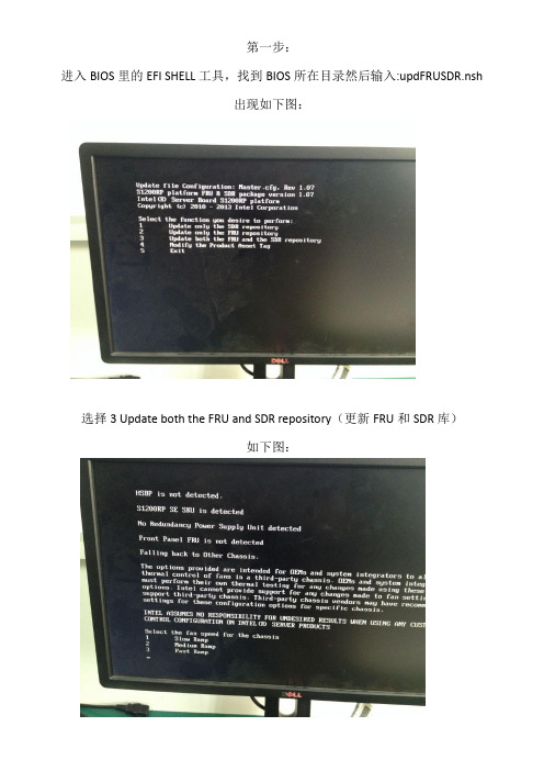
第一步:
进入BIOS里的EFI SHELL工具,找到BIOS所在目录然后输入:updFRUSDR.nsh
出现如下图:
选择3 Update both the FRU and SDR repository(更新FRU和SDR库)
如下图:
选择2 Medium ramp(中等渐变)
出现如下图:
Is System fan 1 instralled?(已安装系统风扇1?)输入:n Is System fan 2 instralled?(已安装系统风扇2?)输入:n Is System fan 3instralled?(已安装系统风扇3?)输入:n Is System fan 4 instralled?(已安装系统风扇4?)输入:n Is CPU fan 1 instralled?(已安装CPU风扇1?)输入:y
出现如下图:
Does the system have chassis intrusion?(是否有机箱入侵?)输入:n Does the front panel support a NMI button?(前面板支持NMI按钮?)输入:n
Do you want to update the chassis info area of the FRU?(你想更新的FRU底盘信息区?)
输入:n
Do you want to enter the chassis manufacturer name(Additional Field 1)?(你想输入底盘制
造商名称(附加字段1)?)输入:n
Do you want to update the system info area of the FRU?(你想更新的的系统信息区?)输
入:n
出现如下图:
设置完成,重启机器!。
Solaris108-07发行说明

Sun Microsystems,Inc.4150Network CircleSanta Clara,CA95054U.S.A.文件号码820–1877–122007年8月版权所有2008Sun Microsystems,Inc.4150Network Circle,Santa Clara,CA95054U.S.A.保留所有权利。
对于本文档中介绍的产品,Sun Microsystems,Inc.对其所涉及的技术拥有相关的知识产权。
需特别指出的是(但不局限于此),这些知识产权可能包含一项或多项美国专利,或在美国和其他国家/地区申请的待批专利。
美国政府权利-商业软件。
政府用户应遵循Sun Microsystems,Inc.的标准许可协议,以及FAR(Federal Acquisition Regulations,即“联邦政府采购法规”)的适用条款及其补充条款。
本发行版可能包含由第三方开发的内容。
本产品的某些部分可能是从Berkeley BSD系统衍生出来的,并获得了加利福尼亚大学的许可。
UNIX是X/Open Company,Ltd.在美国和其他国家/地区独家许可的注册商标。
Sun、Sun Microsystems、Sun徽标、Solaris徽标、Java咖啡杯徽标、、Java和Solaris是Sun Microsystems,Inc.在美国和其他国家/地区的商标或注册商标。
所有SPARC商标的使用均已获得许可,它们是SPARC International Inc.在美国和其他国家/地区的商标或注册商标。
标有SPARC商标的产品均基于由Sun Microsystems,Inc.开发的体系结构。
OPEN LOOK和Sun TM图形用户界面是Sun Microsystems,Inc.为其用户和许可证持有者开发的。
Sun感谢Xerox在研究和开发可视或图形用户界面的概念方面为计算机行业所做的开拓性贡献。
Sun已从Xerox获得了对Xerox图形用户界面的非独占性许可证,该许可证还适用于实现OPEN LOOK GUI 和在其他方面遵守Sun书面许可协议的Sun许可证持有者。
hangfire无数据库控制台用法 -回复

hangfire无数据库控制台用法-回复Hangfire是一个开源的任务调度框架,它提供了一种简单的方式来在应用程序中执行后台任务。
与传统的任务调度方法相比,Hangfire具有许多优势,其中之一就是它允许使用控制台应用程序而无需数据库的支持。
在本文中,我将一步一步地介绍如何使用Hangfire的控制台应用程序来执行后台任务。
第一步:安装Hangfire首先,我们需要在控制台应用程序中安装Hangfire。
在Visual Studio中,打开项目,右键单击解决方案资源管理器中的项目名称,选择“管理NuGet 程序包”。
在NuGet包管理器控制台中,搜索Hangfire并安装最新版本。
第二步:配置Hangfire安装完Hangfire后,我们需要在应用程序中进行配置。
在Program.cs 文件的Main方法中,添加以下代码:csharpusing Hangfire;using Hangfire.Console;class Program{static void Main(){配置HangfireeConsole();启动Hangfire服务器using (var server = new BackgroundJobServer()){启动控制台Console.WriteLine("Hangfire已启动。
按任意键退出...");Console.ReadKey();}}}上述代码首先使用Hangfire的全局配置类进行配置,通过调用UseConsole方法将Hangfire与控制台整合在一起。
然后,代码创建了一个BackgroundJobServer实例来启动Hangfire服务器。
第三步:定义后台任务现在,我们可以定义我们的后台任务了。
在Program.cs文件的Main方法中,添加以下代码:csharpusing Hangfire;using Hangfire.Console;class Program{static void Main(){配置HangfireeConsole();启动Hangfire服务器using (var server = new BackgroundJobServer()){定义后台任务BackgroundJob.Enqueue(() => Console.WriteLine("这是一个后台任务"));启动控制台Console.WriteLine("Hangfire已启动。
oc引导 attempting system restart

“OC引导attempting system restart”是一个与计算机系统和操作系统相关的术语。
OC通常指的是OpenCore,一个用于引导macOS的开源引导加载程序。
当你看到“OC引导attempting system restart”这样的消息时,它通常意味着OpenCore正在尝试重新启动你的计算机系统。
这可能发生在几种情况下:
系统更新:当操作系统或固件需要更新时,可能需要重新启动系统以完成安装过程。
系统故障:如果系统遇到严重故障或错误,可能需要重新启动以恢复到正常状态。
配置更改:如果你对系统的配置进行了更改(例如更改了启动参数或硬件设置),可能需要重新启动以使更改生效。
在大多数情况下,“OC引导attempting system restart”是正常的,并且是为了确保系统的稳定性和安全性。
然而,如果系统频繁地尝试重新启动,或者无法成功完成重新启动过程,那么可能存在更深层次的问题,需要进一步调查和解决。
防火墙

(原创)网络ID、计算机名无法修改(灰色)的问题解决近日根据公司安全规定,加入了公用域。
但是突然发现防火墙无法启动,services.msc后,手动启动Windows Firewall/Internet Connection Sharing (ICS) 服务,失败。
提示:拒绝访问。
于是找资料,尝试了MS提供的两种方式:方法1:调用" 安装API InstallHinfSection " 函数以安装Windows 防火墙要安装Windows 防火墙, 请按照下列步骤:1.单击开始,单击运行, 类型cmd然后单击确定。
2.在命令提示符下, 键入以下命令行, 然后按ENTER 键:Rundll32 setupapi,InstallHinfSection Ndi-Steelhead 132 %windir%\inf\netrass.inf3.重新启动Windows,4.单击开始,单击运行, 类型cmd然后单击确定。
5.在命令提示符, 键入以下命令, 然后按ENTER 键:Netsh firewall reset6.单击开始,单击运行, 类型firewall.cpl然后按ENTER 键。
在Windows 防火墙对话框, 单击On (推荐), 并单击确定。
失败!方法2:Windows 防火墙项添加到注册表警告如果正确修改注册表通过注册表编辑器或通过其他方法可能发生Serious 问题。
这些问题可能需要重新安装操作系统。
Microsoft 不能保证能够解决这些问题而。
修改注册表需要您自担风险。
要将Windows 防火墙项添加到注册表, 请按照下列步骤操作:1 .将以下文本复制到记事本, 然后再保存文件作为Sharedaccess.reg:Windows Registry Editor Version 5.00[-HKEY_LOCAL_MACHINE\SYSTEM\CurrentControlSet\Services\SharedAccess] [HKEY_LOCAL_MACHINE\SYSTEM\CurrentControlSet\Services\SharedAccess] "DependOnGroup"=hex(7):00,00"DependOnService"=hex(7):4e,00,65,00,74,00,6d,00,61,00,6e,00,00,00,57,00, 69,00,\ 6e,00,4d,00,67,00,6d,00,74,00,00,00,00,00 "Description"="Provides network address translation, addressing, name resolution and/or intrusion prevention services for a home or small office network." "DisplayName"="Windows Firewall/Internet Connection Sharing (ICS)""ErrorControl"=dword:00000001"ImagePath"=hex(2):25,00,53,00,79,00,73,00,74,00,65,00,6d,00,52,00,6f,00, 6f,00,\74,00,25,00,5c,00,73,00,79,00,73,00,74,00,65,00,6d,00,33,00,32,00,5c,00,73, \00,76,00,63,00,68,00,6f,00,73,00,74,00,2e,00,65,00,78,00,65,00,20,00,2d,00, \ 6b,00,20,00,6e,00,65,00,74,00,73,00,76,00,63,00,73,00,00,00 "ObjectName"="LocalSystem""Start"=dword:00000002"Type"=dword:0000002 0[HKEY_LOCAL_MACHINE\SYSTEM\CurrentControlSet\Services\SharedAccess\Ep och] "Epoch"=dword:00002cd0[HKEY_LOCAL_MACHINE\SYSTEM\CurrentControlSet\Services\SharedAccess\Pa rameters]"ServiceDll"=hex(2):25,00,53,00,79,00,73,00,74,00,65,00,6d,00,52,00,6f,00,6 f,\00,74,00,25,00,5c,00,53,00,79,00,73,00,74,00,65,00,6d,00,33,00,32,00,5c,00, \69,00,70,00,6e,00,61,00,74,00,68,00,6c,00,70,00,2e,00,64,00,6c,00,6c,00,00, \ 00[HKEY_LOCAL_MACHINE\SYSTEM\CurrentControlSet\Services\SharedAccess\Pa rameters\FirewallPolicy][HKEY_LOCAL_MACHINE\SYSTEM\CurrentControlSet\Services\SharedAccess\Pa rameters\FirewallPolicy\DomainProfile][HKEY_LOCAL_MACHINE\SYSTEM\CurrentControlSet\Services\SharedAccess\Pa rameters\FirewallPolicy\DomainProfile\AuthorizedApplications][HKEY_LOCAL_MACHINE\SYSTEM\CurrentControlSet\Services\SharedAccess\Pa rameters\FirewallPolicy\DomainProfile\AuthorizedApplications\List]"%windir%\\system32\\sessmgr.exe"="%windir%\\system32\\sessmgr.exe:*: enabled:@xpsp2res.dll,-22019"[HKEY_LOCAL_MACHINE\SYSTEM\CurrentControlSet\Services\SharedAccess\Pa rameters\FirewallPolicy\StandardProfile][HKEY_LOCAL_MACHINE\SYSTEM\CurrentControlSet\Services\SharedAccess\Pa rameters\FirewallPolicy\StandardProfile\AuthorizedApplications][HKEY_LOCAL_MACHINE\SYSTEM\CurrentControlSet\Services\SharedAccess\Pa rameters\FirewallPolicy\StandardProfile\AuthorizedApplications\List]"%windir%\\system32\\sessmgr.exe"="%windir%\\system32\\sessmgr.exe:*: enabled:@xpsp2res.dll,-22019"[HKEY_LOCAL_MACHINE\SYSTEM\CurrentControlSet\Services\SharedAccess\Se tup] "ServiceUpgrade"=dword:00000001[HKEY_LOCAL_MACHINE\SYSTEM\CurrentControlSet\Services\SharedAccess\Se tup\InterfacesUnfirewalledAtUpdate] "All"=dword:00000001[HKEY_LOCAL_MACHINE\SYSTEM\CurrentControlSet\Services\SharedAccess\En um] "0"="Root\\LEGACY_SHAREDACCESS\\0000""Count"=dword:00000001 "NextInstance"=dword:000000012.双击Sharedaccess.reg 将此文件的内容合并到注册表并可创建防火墙项。
sun工作站非正常关机之后处理方案
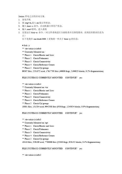
Solairs停电之后的启动方案。
1.家电开机2.按stop+A,进入ok提示符状态。
3.键入boot –s命令,启动机器只单用户状态。
4.输入root+密码,进入系统5.反复运行fsck –y 命令。
(对文件系统进行全面检查并且修复错误,直到没有错误信息为止)以下是我在sun blade2000上采集的一些关于fack –y的信息:# fsck -y** /dev/rdsk/c1t1d0s0** Currently Mounted on /** Phase 1 - Check Blocks and Sizes** Phase 2 - Check Pathnames** Phase 3 - Check Connectivity** Phase 4 - Check Reference Counts** Phase 5 - Check Cyl groups99307 files, 2531872 used, 17617793 free (49609 frags, 2196023 blocks, 0.2% fragmentation) FILE SYSTEM IS CURRENTL Y MOUNTED. CONTINUE? yes** /dev/rdsk/c1t1d0s4** Currently Mounted on /var** Phase 1 - Check Blocks and Sizes** Phase 2 - Check Pathnames** Phase 3 - Check Connectivity** Phase 4 - Check Reference Counts** Phase 5 - Check Cyl groups10801 files, 131584 used, 9945388 free (956 frags, 1243054 blocks, 0.0% fragmentation) FILE SYSTEM IS CURRENTL Y MOUNTED. CONTINUE? yes** /dev/rdsk/c1t1d0s3** Currently Mounted on /opt** Phase 1 - Check Blocks and Sizes** Phase 2 - Check Pathnames** Phase 3 - Check Connectivity** Phase 4 - Check Reference Counts** Phase 5 - Check Cyl groups10410 files, 359109 used, 7700896 free (35840 frags, 958132 blocks, 0.4% fragmentation) FILE SYSTEM IS CURRENTL Y MOUNTED. CONTINUE? yes** /dev/rdsk/c1t1d0s5** Currently Mounted on /usr/users** Phase 1 - Check Blocks and Sizes** Phase 2 - Check Pathnames** Phase 3 - Check Connectivity** Phase 4 - Check Reference Counts** Phase 5 - Check Cyl groups18648 files, 5187586 used, 14962079 free (6191 frags, 1869486 blocks, 0.0% fragmentation) 6.键入命令/usr/sbin/init0 关机进入OK提示符下。
aruba交换机配置-实战篇

aruba交换机配置-实战篇一,忘记密码按以下操作超级账号密码passwordforgetme!!Admin 密码修改ArubaS2500-24P) (config) #mgmt-user admin rootPassword:******** //admin123!Re-Type password:******** //admin123!(ArubaS2500-24P) (config) #endEnable 密码重新设置(ArubaS2500-24P) (config) #enable secret?secret Enter the enable password(ArubaS2500-24P) (config) #enable secretPassword:****** 、直接输入新密码、Re-Type password:****** 再次输入这个账号只能用于需改密码,需要配置的话要退出用admin账号进入才能操作二,交换机初始化<<<<< Welcome to Aruba Networks - Aruba S2500-24P >>>>>User: adminPassword: ******** ///admin123//默认密码(ArubaS2500-24P) >enablePassword:****** //enableQuick-setup helps in setting the basic configuration of the system Autoconfiguration of system will be stopped, if Quick-setup is launched by userInvoke Quick-setup (y|n) [y]:y***************** Welcome to the ArubaS2500-24P setup dialog ***************** This dialog will help you to set the basic configuration for the switch.These settings, except for the Country Code, can later be changed from the Command Line Interface or Graphical User Interface.Commands: Submit input or use [default value], HelpBack, Forward, Line begin, Line endDelete, Delete back, Delete to end of linePrevious question , Restart beginning, to exitEnter System name [ArubaS2500-24P]: aruba2500-xmu-2fConfigure inband management VLAN [yes|no]: yes 是否开启管理VLANInband management vlan id [1]: 711 管理VLAN段Enter the member interfaces for management VLAN (Example 0/0/0,0/0/1): 0/0/23,0/1/1 添加需要trunk的端口Enter management VLAN IP address [172.16.0.254]: 172.31.11.2 管理ipEnter mgmt VLAN interface subnet mask [255.255.255.0]: 回车Enter Out of band management interface IP address [none]: 回车Enter IP Default gateway [none]: 172.31.11.1 网关Enter Country code (ISO-3166), for supported list: CN 中国You have chosen Country code CN for China (yes|no)?: yes Enter Time Zone [PST-8:0]: CST+8:0Enter Time in UTC [03:48:15]:Enter Date (MM/DD/YYYY) [7/4/2013]:Enter Password for admin login (up to 32 chars): *********//admin123!Re-type Password for admin login: ********* //admin123!Enter Password for enable mode (up to 15 chars): ****** //enablleRe-type Password for enable mode: ****** //enable Current choices are:System name: aruba2500-xmu-2fConfigure inband management VLAN: yesvlan id for inband management [1-4094]: 711Members interfaces of management VLAN: 0/0/23,0/1/1IP address of management VLAN: 172.31.11.2Management VLAN interface subnet mask: 255.255.255.0IP Default gateway: 172.31.11.1Country code: CNTime Zone: CST+8:0Type to go back and change answer for any questionDo you wish to accept the changes (yes|no|abort): yesCreating configuration...Done.Configuring...Saving Configuration...Configuration Saved.(aruba2500-xmu-2f) #configure terEnter Configuration commands, one per line. End with CNTL/Z(aruba2500-xmu-2f) (config) #telnet cli //开启telnet功能(aruba2500-xmu-2f) (config) #end(aruba2500-xmu-2f) #show ip interface briefInterface IP Address / IP Netmask Admin Protocolvlan 711 172.31.11.2 / 255.255.255.0 Up Upmgmt unassigned / unassigned Up Down(aruba2500-xmu-2f) #ping 172.31.11.1Press 'q' to abort.Sending 5, 100-byte ICMP Echos to 172.31.11.1, timeout is 2 seconds:.....Success rate is 0 percent (0/5)(aruba2500-xmu-2f) #ping 172.31.11.1(aruba2500-xmu-2f) #configure ter(aruba2500-xmu-2f) (config) #interface-group gigabitethernet ap 创建端口组(aruba2500-xmu-2f) (gigabitethernet "ap") #apply-to 0/0/0-0/0/23 把0/0/0-0/0/23加入组中(aruba2500-xmu-2f) (gigabitethernet "ap") #exit(aruba2500-xmu-2f) (switching profile "ap") #vlan 712 创建vlan712(我给AP用的)(aruba2500-xmu-2f) (VLAN "712") #exit (aruba2500-xmu-2f) (config) #interface-profile switching-profile ap(aruba2500-xmu-2f) (switching profile "ap") #access-vlan 712 关联(aruba2500-xmu-2f) (switching profile "ap") #exit(aruba2500-xmu-2f) (config) #interface-profile poe-profile ap(aruba2500-xmhu-2f) (Power over Ethernet profile "ap") #enable 开启POE供电功能(aruba2500-xmu-2f) (Power over Ethernet profile "ap") #exit(aruba2500-xmu-2f) (config) #interface-group gigabitethernet ap(aruba2500-xmu-2f) (gigabitethernet "ap") #switching-profile ap 应用到端口(aruba2500-xmu-2f) (gigabitethernet "ap")#poe-profile ap 应用到端口(aruba2500-xmu-2f) (gigabitethernet "ap") #end如果想把那个端口trunk,可以这样(aruba2500-xmu-2f) (config) #interface g 0/0/2(aruba2500-xmu-2f) #switching-profile Upstream-profile删除的话就加no(aruba2500-xmu-2f) #no switching-profile Upstream-profile 如果要把那个端口加入vlan20(aruba2500-xmu-2f) #vlan 20(aruba2500-xmu-2f) (VLAN "20") #exit(aruba2500-xmu-2f) (config) #interface-profile switching-profile 20(aruba2500-xmu-2f) (switching profile "ap") #access-vlan 20 (aruba2500-xmu-2f) (config) #interface g 0/0/2(aruba2500-xmu-2f) #switching-profile 20删除就加no(aruba2500-xmu-2f) #no switching-profile 20或者(aruba2500-xmu-2f) #no switching-profile三,升级配置把网线接到23口,电脑开启tftp服务器软件ArubaS2500-24P) (config) #interface-profile switching-profile ftp //--创建模板FTP (ArubaS2500-24P) (switching profile "ftp") #access-vlan 1 关联vlan1(ArubaS2500-24P) (switching profile "ftp") #exit(ArubaS2500-24P) (config) #interface gigabitethernet 0/0/23 (ArubaS2500-24P) (gigabitethernet "0/0/23") #switching-profile ftp //启用ftp(ArubaS2500-24P) (gigabitethernet "0/0/23") #exit(ArubaS2500-24P) (config) #interface vlan 1(ArubaS2500-24P) (vlan "1") #ip address 10.0.0.1 255.0.0.0 (ArubaS2500-24P) (vlan "1") #exit(ArubaS2500-24P) (config) #end(ArubaS2500-24P) #ping 10.0.0.5(ArubaS2500-24P) #(ArubaS2500-24P) #(ArubaS2500-24P) #copy ftp: 10.0.0.5 admin ArubaOS_MAS_7.2.2.1_38712 system: partition 0 Password:****** //---admin和密码是ftp的用户名和没密码,10.0.0.5是电脑的ip Press 'q' to abort.Copying file:............................................................File copied successfully.Saving file to flash:...Member-0:The system will boot from partition 0 during the next reboot.(ArubaS2500-24P) #re?reload Coldstart the switchrename rename a filerestore restore file or configuration(ArubaS2500-24P) #reloadDo you want to save the configuration(y/n): nDo you really want to restart the system(y/n): y System will now restart!Shutdown processing started(aruba2500-xmu-2f) #write memory 保存Saving Configuration...Configuration Saved.(aruba2500-xmu-2f) #show running-config Building Configuration...## Configuration file for ArubaOSversion 7.2enable secret "******"telnet clihostname "aruba2500-xmu-2f"clock timezone CST 8location "Building1.floor1"controller config 3ip access-list eth validuserethaclpermit any!!!ip access-list stateless dns-acl-statelessany any svc-dns permit!ip access-list stateless http-acl-statelessany any svc-http permit!ip access-list stateless https-acl-statelessany any svc-https permit!ip access-list stateless icmp-acl-statelessany any svc-icmp permitip access-list stateless logon-control-stateless any any svc-icmp permitany any svc-dns permitany any svc-dhcp permitany any svc-natt permit!ip access-list session validusernetwork 169.254.0.0 255.255.0.0 any any denyany any any permitipv6 alias any6 alias any6 any permit!user-role authenticatedaccess-list stateless allowall-stateless!user-role denyall!user-role guestaccess-list stateless http-acl-statelessaccess-list stateless https-acl-statelessaccess-list stateless dhcp-acl-statelessaccess-list stateless icmp-acl-statelessaccess-list stateless dns-acl-stateless!user-role logonaccess-list stateless logon-control-stateless!!crypto ipsec transform-set default-boc-bm-transform esp-3des esp-sha-hmac crypto ipsec transform-set default-rap-transform esp-aes256 esp-sha-hmac crypto isakmp eap-passthrough eap-tlscrypto isakmp eap-passthrough eap-peapcrypto isakmp eap-passthrough eap-mschapv2mgmt-user admin root 9a05893a01941ea9fadbe8f7f92075bc5b5c8189ef96622520 no firewall attack-rate cp 1024ipv6 firewall ext-hdr-parse-len 100!firewall cppacket-capture-defaults tcp disable udp disable sysmsg disable other disable !ip domain lookup!country CNaaa authentication mac "default"!aaa authentication dot1x "default"!aaa server-group "default"auth-server Internalset role condition role value-of!aaa profile "default"!aaa authentication captive-portal "default"!aaa authentication vpn "default"!aaa authentication mgmt!aaa authentication wired!web-server!aaa password-policy mgmt!traceoptionsqos-profile "default"!policer-profile "default"!ip-profiledefault-gateway 172.31.11.1!lcd-menu!interface-profile ospf-profile "default"area 0.0.0.0!interface-profile pim-profile "default"!interface-profile igmp-profile "default"!stack-profile!ipv6-profile!interface-profile switching-profile "ap"access-vlan 712!interface-profile switching-profile "default"!interface-profile switching-profile "Upstream-profile" switchport-mode trunk!interface-profile poe-profile "ap"enable!interface-profile poe-profile "default"!interface-profile poe-profile "poe-factory-initial"enable!interface-profile enet-link-profile "default"!interface-profile lldp-profile "default"!interface-profile lldp-profile "lldp-factory-initial"lldp transmitlldp receivemed enable!interface-profile mstp-profile "default"!interface-profile pvst-port-profile "default"!vlan-profile mld-snooping-profile "default"!vlan-profile igmp-snooping-profile "default"!vlan-profile igmp-snooping-profile "igmp-snooping-factory-initial" !spanning-treemode mstp!gvrp!mstp!lacp!vlan "1"igmp-snooping-profile "igmp-snooping-factory-initial" !vlan "711"!vlan "712"!interface gigabitethernet "0/1/1"switching-profile "Upstream-profile"!interface vlan "711"ip address 172.31.11.2 255.255.255.0!interface mgmt!interface-group gigabitethernet "ap"apply-to 0/0/0-0/0/23poe-profile "ap"switching-profile "ap"!interface-group gigabitethernet "default"apply-to ALLlldp-profile "lldp-factory-initial"poe-profile "poe-factory-initial"!snmp-server view ALL oid-tree iso includedsnmp-server group ALLPRIV v1 read ALL notify ALLsnmp-server group ALLPRIV v2c read ALL notify ALLsnmp-server group ALLPRIV v3 noauth read ALL notify ALL snmp-server group AUTHPRIV v3 priv read ALL notify ALL snmp-server group AUTHNOPRIV v3 auth read ALL notify ALL snmp-server enable trapprocess monitor logend(aruba2500-xmu-2f) #(aruba2500-xmu-2f) #(aruba2500-xmu-2f) #(aruba2500-xmu-2f) #write memorySaving Configuration...Configuration Saved.(aruba2500-xmu-2f) #show ip interface briefInterface IP Address / IP Netmask Admin Protocol vlan 711 172.31.11.2 / 255.255.255.0 Up Up mgmt unassigned / unassigned Up Down(aruba2500-xmu-2f) #ping 172.31.11.1Press 'q' to abort.Sending 5, 100-byte ICMP Echos to 172.31.11.1, timeout is 2 seconds:Success rate is 100 percent (5/5), round-trip min/avg/max = 1.525/1.922/2.534 ms(aruba2500-xmu-2f) #write memorySaving Configuration...Configuration Saved.(aruba2500-xmu-2f) #configure terminalCNTL/Z(aruba2500-xmu-2f) (config) #end(aruba2500-xmu-2f) #(aruba2500-xmu-2f) #(aruba2500-xmu-2f) #(aruba2500-xmu-2f) #copy ftp: 172.1.1.1.1 ?Enter the user name(aruba2500-xmu-2f) #copy ftp: 172.1.1.1.1 endwin ?Enter the file name(aruba2500-xmu-2f) #copy ftp: 172.1.1.1.1 endwin ArubaOS_MAS_7.2.2.1_38712 ? flash: Copy to the flash file system member: Copy to a stack membersystem: System Partition(aruba2500-xmu-2f) #copy ftp: 172.1.1.1.1 endwin ArubaOS_MAS_7.2.2.1_38712 system: partition 0 ?(aruba2500-xmu-2f) #copy ftp: 172.1.1.1.1 endwin ArubaOS_MAS_7.2.2.1_38712 system: partition 0 ?(aruba2500-xmu-2f) #dir-rw-r--r-- 1 root root 35729264 Jul 4 09:36 ArubaOS_MAS_7.2.2.1_38712.1_38712-rw-r--r-- 1 root root 4905 Jul 4 11:55 default.cfg-rw-r--r-- 1 root root 40 Jul 4 11:46 stack_db.dbdrwx------ 2 root root 4096 Jul 4 11:00 tpm(aruba2500-xmu-2f) #copy running-config ?flash: Copy to the flash file systemftp: Ftp file systemstartup-config Copy to Startup configurationtftp: TFTP file system(aruba2500-xmu-2f) #configure terCNTL/Z(aruba2500-xmu-2f) (config) #interface vlan 1(aruba2500-xmu-2f) (vlan "1") #ip address 192.168.100.1 255.255.255.0(aruba2500-xmu-2f) (vlan "1") #exit(aruba2500-xmu-2f) (config) #interface gigabitethernet 0/0/23(aruba2500-xmu-2f) (gigabitethernet "0/0/23") #switching-profile ?Profile name(aruba2500-xmu-2f) (gigabitethernet "0/0/23") #exit(aruba2500-xmu-2f) (config) #interface-profile switching-profile ftp(aruba2500-xmu-2f) (switching profile "ftp") #access-vlan vlan 1^% Invalid input detected at '^' marker.(aruba2500-xmu-2f) (switching profile "ftp") #access-vlan 1 (aruba2500-xmu-2f) (switching profile "ftp") #exit(aruba2500-xmu-2f) (config) #interface gigabitethernet 0/0/23(aruba2500-xmu-2f) (gigabitethernet "0/0/23") #switching-profile ftp(aruba2500-xmu-2f) (gigabitethernet "0/0/23") #end(aruba2500-xmu-2f) #ping 192.168.100.100Press 'q' to abort.Sending 5, 100-byte ICMP Echos to 192.168.100.100, timeout is 2 seconds:Success rate is 100 percent (5/5), round-trip min/avg/max = 1.641/4.102/13.924 ms(aruba2500-xmu-2f) #copy running-config ?flash: Copy to the flash file systemftp: Ftp file systemstartup-config Copy to Startup configurationtftp: TFTP file system(aruba2500-xmu-2f) #copy running-config ftp: ?Enter the ftp server ip address(aruba2500-xmu-2f) #copy running-config ftp: 192.168.100.100 ?Enter the ftp user name(aruba2500-xmu-2f) #copy running-config ftp: 192.168.100.100 endwin ?Enter the ftp user password(aruba2500-xmu-2f) #copy running-config ftp: 192.168.100.100 endwin endwin ?Enter the file name(aruba2500-xmu-2f) #copy running-config ftp: 192.168.100.100 endwin endwin s2500.cfg (aruba2500-xmu-2f) # (aruba2500-xmu-2f) #(aruba2500-xmu-2f) #copy running-config ftp: 192.168.100.100 endwin endwin s25001.txt (aruba2500-xmu-2f) #。
东软防火墙配置过程
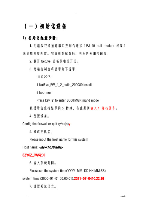
(一)初始化设备1)初始化配置步骤:1.用超级终端通过串口控制台连接〔RJ-45 null-modem 线缆〕来完成初始配置。
完成初始配置后,可不再使用控制台。
2.翻开NetEye 设备的电源开关。
3.终端控制台将显示如下提示:LILO 22.7.11 NetEye_FW_4_2_build_200080.install2 bootmgrPress key '2' to enter BOOTMGR mand mode该提示信息将显示约5 秒钟,在此期间输入1 并按回车。
4.配置设备。
Config the firewall or quit (y/n)(n)y5.修改主机名。
Please input the host name for this systemHost name: <new hostname>SZYCZ_FW52006.输入系统时间。
Please set the system time(YYYY-MM-DD HH:MM:SS)system time (2000-01-01 00:00:01):2021-07-0410:22:367.设置系统语言。
Please set system language(1) English(2) ChinesePlease input a choice[1-2,q](2) <1、2 或q>选择2,中文,回车8.更改根管理员口令。
〔此步骤可选,但东软强烈建议首次登录后修改口令。
〕Changing default password of root?(y/n)(y):Old password(6-128): neteyePassword(6-128): < 新密码>Repeat Password(6-128): < 新密码>这里我们不更改它的默认密码,选择n9.添加根系统管理员及选择登录方式。
Creating an administrator?(y/n)(y):Username: < 用户名>Please select a login type(1) Web(2) Telnet(3) SSH(4) SCMPlease input a choice[1-4](1)(example: 1,2,3):1,2,3,4Password(6-128): < 密码>Repeat Password(6-128): < 密码>选择y,添加ycz用户,设备相应密码,Web管理,Telnet。
windowsfirewall authorization driver -回复

windowsfirewall authorization driver -回复Windows Firewall是Windows操作系统所提供的一种网络安全服务。
在Windows操作系统中,授权驱动程序(authorization driver)是Windows Firewall的一个重要组成部分,它负责控制哪些网络连接可以通过Windows防火墙,并且根据预设的规则和策略进行授权控制。
本文将详细介绍Windows Firewall的授权驱动程序。
首先,我们需要了解Windows Firewall的基本概念。
Windows Firewall是一种个人电脑或服务器在Internet上建立保护的软件。
它的主要目标是保护计算机免受不良或危险的网络攻击。
Windows Firewall通过检查进出计算机的网络流量并根据预设的规则来决定是否允许通过或拦截网络流量。
授权驱动程序就是负责进行这一授权决策的核心组件。
授权驱动程序的主要职责是读取Windows Firewall配置文件中的规则和策略,并根据这些规则和策略对传入和传出的网络流量进行授权判断。
它通过检查网络流量的源地址、目标地址、端口号等信息,与配置文件中的规则进行匹配,并根据匹配结果判断是否允许通过该网络连接。
具体而言,授权驱动程序可以被分为两个主要部分:策略过滤模块和包过滤模块。
策略过滤模块负责按规定的策略对网络流量进行过滤。
策略过滤模块读取Windows Firewall配置文件中的策略信息,并根据这些策略信息对网络流量进行授权判断。
例如,某个策略规定只有来自指定IP地址的流量被允许通过防火墙,那么授权驱动程序的策略过滤模块将会根据这个策略对传入的网络流量源地址进行匹配,并根据匹配结果决定是否允许通过。
包过滤模块则负责对单一的数据包进行过滤。
包过滤模块根据Windows Firewall配置文件中的规则信息对单个网络数据包进行授权判断。
例如,某个规则规定只有目标端口为80的HTTP协议数据包被允许通过防火墙,那么授权驱动程序的包过滤模块将会按照这个规则对传入的数据包进行匹配,并根据匹配结果决定是否允许通过。
