电源规格书JP-026 12V2A
各个国家电源规格详解
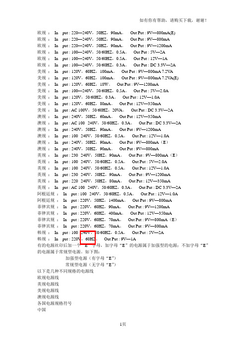
美规:In put : 120V,50/60HZ,0.3A。Out Put : 12V—1.0A
美规:In put : 120V,60HZ,80mA。Out Put : 12V—350mA
美规:In put : AC 100V,50/60HZ,20VA。Out Put : DC 3.3V—2A
美规:In put : 120V,60HZ,100mA。Out Put : 9V—800mA 7.2VA
美规:In put : 120V,60HZ,100mA。Out Put : 9V—800mA 7.2VA(E)
美规:In put : 120V,60HZ,18W。Out Put : 9V—1200mA
菲律宾规:In put : 220V,60HZ,70mA。Out Put : 9V—800mA
韩规:In put : 100--240V,50/60HZ,0.5A。Out Put : 5V—2A
韩规:In put : 220V,60HZ。Out Put : 9V—1A
有的电源丝印后加一个“E”字母,加字母“E”的电源属于加强型的电源;不加字母“E”的电源属于常规型电源。如下图:
澳规:In put : 100--240V,50/60HZ,0.5A。Out Put : 12V—1.0A
澳规:In put : 240V,50HZ,90mA。Out Put : 9V—800mA(E)
澳规:In put : 240V,50HZ,90mA。Out Put : 9V—800mA
英规:In put : 230--240V,50HZ,90mA。Out Put : 9V—800mA(E)
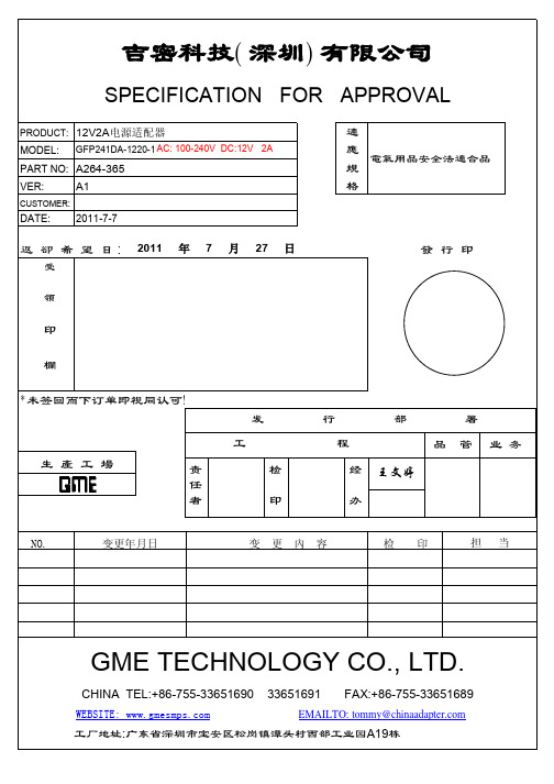
12V2A电源适配器规格书

电源适配器 Power adapter
版本/ Version SHEET
OF
K-C7 系列
A1
4
14
3.8 过冲/Overshoot: 在电源开启或关闭的时候,最大 15%. 15% Max.When power supply at turn or turn off.
4、保护功能/PROTECTION FUNCTION:
5.4 跌落试验/Dropping Packed: 插墙式跌落高度为 1200mm、桌面式跌落高度为 1000mm; 1.2M for wallmount type and 1000mm for desktop type as above described; 测试台面是厚 13mm 的夹木板,离地面高 19-20mm The horizontal surface consists of hardwood at least 13mm thick, mounted on two layers of plywood each 19mm to 20mm thick,all supported on a concrete or equivalent non -resilient floor.
美规外壳
澳规外壳
金宝通/BESTGK R&D
英规外壳
电源适配器 Power adapter
欧规,韩规外壳(仅插脚不同)
版本/ Version SHEET
OF
K-C7 系列
A1
7
14
8、线材/CORD:
具体根据客户需求!/ Specific according to customer demand
金宝通/BESTGK R&D
Vin100Vac 60Hz Io=Rated Current 输入 100Vac 60Hz 额定电流
12V2A电源适配器
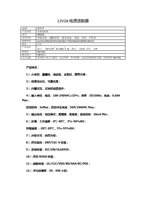
品牌
森树强
产品类型
电源适配器
型号
SK02G
适用设备
智能设备、LED照明、通讯设备、电脑、安防、手机等
插脚类型
UL/CUL/PSE/CE/FCC/GS/CB/C-TICK/SAA/KC/BSMI/CB/CCC
ห้องสมุดไป่ตู้颜色
白色
产品电压
输入: 100-240V~ 50/60Hz~0.6A输出:12V2A功率:24W
启动时间:3sMax;启动冲击电流:50A/240VAC Max;
5).输出特点:恒压模式;高精度,低噪音;保持时间:20mS Min;
6).环境:工作温度:0℃-40℃,5%-90%RH;
存储温度:-20℃-85℃,5%-95%RH;
7).冷却方式:自然冷却;
8).符合能效:ERP/CEC-V标准;
转换率
85%-88%
输出接口
USB输出
安全功能
采用进口电子元器件,安全环保,具有短路、过流及短路保护功能;转换效率85%-88%;
产品特点:
1).小体积、重量轻、流线型、全密封、携带方便;
2).极高性价比,可靠性高;
3).内置过压、过流和短路保护;
4).输入特性:电压:100-240VAC±10%;频率:50/60Hz;电流:0.60A Max;
9).安规标准:IEC/EN/UL60950;
10).符合ROHS标准;
11).插脚类型:UL/CCC/VDE/BS/SAA/KC/PSE;
12).平均故障率:50,000小时;
12V2A电源适配器

基于PT2202的24W AC-DC开关电源基本特性电流控制模式的反激式开关变换器交流90~264V,50~60Hz工作范围平均效率和待机功耗均超过能源之星V5.0标准自动恢复的过流及负载短路保护功能自动恢复的输出过压保护工作环境温度0~40℃,湿度20%~80%电原理图和实物照片电路如图1,交流侧输入有2A保险丝F1和抗浪涌负温度系数热敏电阻NTC1。
CX1和FL2组成差共模EMI滤波器,BD1是全桥整流器,C1为高压母线电容。
T1,Q1,D51组成反激式电路架构,U1为电流控制型PWM控制IC。
当接通交流市电,母线电压经由R3,R4为IC PT2202提供启动电流,当VCC电压达到芯片启动电压,芯片开始工作,随着输出电压的上升,当变压器辅助绕组正向电压超过芯片最低工作电压时,芯片供电电流开始主要由变压器辅助绕组供电。
二次侧芯片TL431提供反馈电压比较基准2.5V以及误差放大信号,经由光耦隔离放大,产生原边的反馈控制信号FB,作为电流内环的一个比较基准,控制原边MOS管的峰值电流,实现输出的恒压控制。
R7,R8用于设置MOS管最大峰值电流,实现限功率控制。
图1 电原理图图2是电源的实物照片,45个元件安装在70×42.5×25mm的环氧单面印制板上,PCB走线按照电力电子规范要求设计。
图2 实物照片电气参数和BOM电源主要电气参数如表1所示,表中开关频率为最高工作频率,满载测试条件。
在全电压输入范围内,实现额定功率24W输出,实际最大输出功率超过30W。
表2是详细的材料清单,为了保证质量,尽量选用推荐产商的元器件。
表1:电气参数表表2:材料清单序号元件名称型号厂商1 BD1 整流桥KBP206 PAN JIT2 C1 铝电解电容47uF/400V NICHICON3 C2 陶瓷电容2200pF/1KV AVX4 C31 陶瓷电容1uF/25V AVX5 C32 陶瓷电容22pF/50V AVX6 C33 铝电解电容22uF/50V NCC7 C51 陶瓷电容1000pF/1KV AVX8 C52 铝电解电容680uF/25V NCC9 C53 陶瓷电容100nF/25V AVX10 CX1 X 电容0.22uF/275V HUA JUNG11 CY1 Y 电容4700pF/250V MURATA12 D1 快速恢复二极管BYV26C VISHAY13 D31 快速恢复二极管FR107 VISHAY14 D51 肖特基二极管STPS41H100CT ST15 D52 发光二极管LED_0 EVERLIGHT16 F1 保险丝 2.5A/250V Cooper17 FL2 共模电感16mH18 Q1 功率场效应管FQP8N60 INFINEON19 R1,R2 SMD电阻1M(1206)TY-OHM20 R3,R4 SMD电阻560K(1206)TY-OHM27 R32 SMD电阻100K(0805)TY-OHM24 R33 SMD电阻47R(0805)TY-OHM25 R34 SMD电阻100R(0805)TY-OHM26 R35 SMD电阻0R(1206)TY-OHM21 R5,R6 SMD电阻200K(1206)TY-OHM28 R51 SMD电阻100R(1206)TY-OHM29 R52,R54 SMD电阻10K(0805)TY-OHM30 R53 SMD电阻1k(0805)TY-OHM31 R55 SMD电阻36K(0805)TY-OHM32 R56 SMD电阻9.1K(0805)TY-OHM22 R7 SMD电阻 6.2 1%(1206)TY-OHM23 R8 SMD电阻1R 1%(1206)TY-OHM33 NTC1 热敏电阻5ohm GE Infrastructure34 T3 变压器EI28 Crpowtech35 U1 控制芯片PT4201 Crpowtech36 U2 光耦PC817 VISHAY37 U3 稳压三极管TL431 ON工作波形1.稳态输出电压,纹波电压图3,图4分别为输入100Vac,输出为满载时输出电压波形和纹波电压波形。
JP系列低压综合配电箱说明书

JP系列低压综合配电箱安装使用说明书1、概述JP系列10kV变压器综合配电箱(以下简称“配电箱”),适用于广大农村配电变压器额定频率交流50Hz,额定工作电压400V,额定电流800A及以下的配电系统中,户外柱上安装使用。
配电箱具备远程在线监测、电能分配、电能计量、无功补偿和剩余电流保护等功能的综合低压成套开关设备与控制设备。
2、型号及含义JP —□/ □补偿容量(kvar)变压器容量(kVA)低压综合配电箱3、执行标准GB 4208 外壳防护等级(IP代码)GB/Z 6829 剩余电流动作保护电器的一般要求GB 7251.12 低压成套开关设备和控制设备第2部分:低压成套开关设备和控制设备第2部分:成套电力开关和控制设备GB/T 10233 低压成套开关设备和电控设备基本试验方法GB 13955 剩余电流动作保护装置安装和运行GB 14048.2 低压开关设备和控制设备第2部分:断路器GB/T 15576 低压成套无功功率补偿装置GB/T 17626.2 电磁兼容试验和测量技术静电放电抗扰度试验GB/T 17626.3 电磁兼容试验和测量技术射频电磁场辐射抗扰度试验GB/T 17626.4 电磁兼容试验和测量技术电快速瞬变脉冲群抗扰度试验GB/T 17626.5 电磁兼容试验和测量技术浪涌(冲击)抗扰度试验DL/T 375 户外配电箱通用技术条件DL/T 499 农村低压电力技术规程DL/T 614 多功能电能表DL/T 620 交流电气装置的过电压保护和绝缘配合4、使用环境条件配电箱的使用环境条件,见表1。
表1 使用环境条件5、主要技术参数配电箱的主要技术参数,见表2、表3。
表3 400kVA配变用,1进3出,有补偿配电箱主要技术参数6、装置功能单元的划分和要求6.1 装置划分为以下单元:a)计量/测量表计单元;b)控制保护单元;c)无功补偿单元。
5.2.1 计量/测量表计单元计量装置设单独计量室单元,集中布置,密封隔离,单独设门,并设观察窗。
PowerWave 2 低压电源分发系统规范(复印版 004,2017年11月17日)说明书

Guide Specifications (Revision 004, 11/17/2017)_______________________________________________________________________________Power Distribution, Inc. – Transform. Distribute. Monitor. ™11 GENERAL1.1 SummaryThis specification covers the electrical characteristics and general requirements for a continuous opening, low voltage, vertical or horizontal power busway distribution system.System shall be designed primarily as an overhead distributed power distribution center. System shall be designed to be located near critical distribution points to power specific loads, servers and work stations. Once installed, the completed system will provide a manageable, economical means for the distribution of power and communications. Distribution of power and communications will be made through the adaptation of plug-in Tap Off Units mounted securely to the busway rails.Tap Off points shall be easily modifiable for phase configuration and be safe for installation and decommissioning while the busway is in its live state.System shall be 100% recyclable and be shipped in recyclable containers and packing.1.2 StandardsThe PDI PowerWave 2 Bus System shall be certified through ETL for the following standards:• UL 857• CSA C22.2 No. 27-09 • IEC 61439-2•C-TICK (Australia)In addition, the PowerWave 2 Bus System shall be designed, manufactured, tested, and installed in compliance with the following standards:• IEC 60264 • IEC 60364 • IEC 61439-1 • ISO 9001: 2015• Low Voltage Directive 73/23/EEC: Amendment 93/68/EEC • NEC Art. 364 – 19 Busway • NEMA AB-1 • NEMA KS-1 • NFPA-70 • UL 60950-1Guide Specifications (Revision 004, 10/15/2017)_______________________________________________________________________________Power Distribution, Inc. – Transform. Distribute. Monitor. ™21.3 System Description1.3.1 Environmental RequirementsThe PowerWave 2 Bus System shall have the following environmental requirements for operation and storage requirements:•Temperature ranges:o Storage: -40°F to 158 °F [-40°C to 70°C] o Operating:▪ 250 – 400A Busway: 140°F [60°C] Maximum ▪ 800A Busway: 104°F [40°C] Maximum ▪ BCMS: 104°F [40°C] Maximum•Relative Humidity:o Storage: Store in dry location in original packaging o Operating: 0% to 95% non-condensing •Operating Altitude:o Up to 6,600 ft. [2,000m] above Mean Seal Level; the unit is de-rated if operatedabove this altitude.1.3.2 Electrical SpecificationThe PowerWave 2 Busway System shall accept input power rated at 250A, 400A, and 800A. The PowerWave 2 Busway System shall accept alternating current frequencies of 50 Hz, 60 Hz, and 400 Hz.The PowerWave 2 Busway System shall accept input voltages of 208/120V, 380/220V, 400/230V, 415/240V, 480/277V, 600/377V or any voltage less than or equal to 600V. Voltage drop-off along the bus run per 100' of installed system shall be approximately 2V.The PowerWave 2 Busway System shall have the following short-circuit withstand ratings:•250A Bus Systems:o 42 kAIC up to 208VAC o 35 kAIC up to 480VAC o 22 kAIC up to 600VAC •400A Bus Systems:o 42 kAIC up to 208VAC o 35 kAIC up to 480VAC o 22 kAIC up to 600VAC •800A Bus Systems:o 42 kAIC up to 600VGuide Specifications (Revision 004, 10/15/2017)_______________________________________________________________________________Power Distribution, Inc. – Transform. Distribute. Monitor. ™31.4 Documentation1.4.1 DrawingsPowerWave 2 Busway System submittal drawings shall be furnished for busway and Tap Off Units. 1.4.2 Installation and Operations DocumentationA PowerWave 2 Busway System Installation and Operations Manual shall be furnished. 1.4.3 Contact ListA contact list for PDI functions, such as Service and Accounting, shall be provided.1.5 WarrantyThe manufacturer shall provide a warranty against defects in materials and workmanship for a period of 12 months from initial start-up or 18 months from shipping date, whichever period ends first.1.6 Quality AssuranceThe PDI PowerWave 2 Busway shall be designed and manufactured according to internationallyrecognized quality standards, including those listed in section 1.2 Standards . The manufacturer shall be ISO 9001 certified.The PDI PowerWave 2 Busway shall be factory tested before shipment. Testing shall include at minimum:• Hi-Pot Test at two times the unit’s rated voltage plus 1000 volts, per UL 60950 • Receptacle or Connector and Breaker Configuration • Phase Wiring/ Connectivity Test •Ground Fault Path Test2 PRODUCT2.1 Busway2.1.1 Busway SystemThe busway system shall be constructed to allow any individual section to be removed and replaced without disruption to adjacent sections.The busway system shall be finger safe IP2X rated and tested.Guide Specifications (Revision 004, 10/15/2017)_______________________________________________________________________________Power Distribution, Inc. – Transform. Distribute. Monitor. ™42.1.2 Bus Rail HousingBus rail housing shall be of single-piece extruded aluminum that is designed to act as a 100% ground conductor. The extrusion shall have a corrosion resistant anodized surface finish. Standard lengths shall include 3, 5, 6, 10, and 12 foot. Removing the end cap assembly shall allow extending the bus run length.The extruded housing must accommodate the direct insertion of hanger assemblies which attach directly to the housing assembly.The complete assembly shall be of the continuous opening design and shall have a slotted opening on one side of the bus to accommodate the insertion of the Tap Off Units. 2.1.3 Bus Rail System WeightThe busway system shall be in accordance with the following weights: 250 Amp: 6.8 lbs/ft. [10.1 kg/m] 400 Amp: 9.6 lbs/ft. [14.3 kg/m]800 Amp: 19.4 lbs/ft. [28.9 kg/m]2.2 Busway2.2.1 Bus Bar ConstructionAll phase and neutral conductors shall be made of copper with a minimum of 98.9% electrical grade purity that is silver plated with a nickel undercoat per ASTM B700-08 and sized to handle a minimum of 100% of the continuously rated current. All conductors shall be electrically isolated from the housing using a Class H fiber-reinforced Glastic material with non-propagating properties. All insulators must be UL recognized. 2.2.2 Bus Power JunctionsAll critical bus power junctions shall be made with CouplerTek™ technology and shall bemaintenance fee. Bolted bus connections that can loosen, sag, and result in connection hotspots are not allowed.2.2.3 Bus Bar 150% Neutral (Optional)A 150%-rated Neutral shall be available as a factory integrated feature of the bus rails. 2.2.4 Isolated Ground Bus Bar (Optional)An Isolated Ground Bus Bar shall be optionally installed in the existing rail channel and tested.Guide Specifications (Revision 004, 10/15/2017)_______________________________________________________________________________Power Distribution, Inc. – Transform. Distribute. Monitor. ™52.2.5 Conductive Fittings and ComponentsAll conductive fittings including Tees, Elbows, etc. shall be of the same material from the samemanufacturer. All insulating material shall be Class H fiber-reinforced Glastic material. All insulators must be UL recognized. 2.2.6 Insertion PointsThe entire bus open channel with the exception of the small area at the bus bar coupling shall be available for Tap Off Unit insertion. The maximum busway coupler keep-out area shall be as follows:• 250-400 Amp = 3.75" keep-out area •800 Amp = 9" keep-out area2.3 Suspension and Bus Hangers2.3.1 Hanger AssembliesHanger assemblies shall allow ceiling mounting and must not interfere or obstruct the housingopening intended for the installation of Tap Off Units. The Installing Contractor shall supply threaded rod where required for hanging the busway.The busway shall be hung from the ceiling using threaded rod. The Installing Contractor shall be responsible for supplying the threaded rod and making connections to bus hangars and End Feed enclosures and to the supporting structure. Maximum hanger spacing will be no more than 10' on center.2.3.2 Vertical or Horizontal SuspensionBus Hangers shall be available for vertical or horizontal bus mount applications. Hangers shall be compatible with standard hardware and Unistrut.2.4 End FeedEnd Feeds shall be designed for conduit landing and input feed connection. Vertical or horizontal End Feeds shall be available.2.5 Tap Off Units2.5.1 Tap Off Unit EnclosureThe Tap Off Unit enclosure shall be available in vertical- and horizontal-mount configurations and shall be compatible with the 250, 400, and 800 amp bus rails.Tap Off Units used for vertical-mount supporting a maximum of two receptacles shall be available with Infrared translucent material for the purpose of thermal scanning breaker terminals.Guide Specifications (Revision 004, 10/15/2017)_______________________________________________________________________________Power Distribution, Inc. – Transform. Distribute. Monitor. ™6Plug-in Tap Off Units shall be polarity matched to the busway system. 2.5.2 Tap Off Unit Electrical Specification The Tap Off Unit maximum amperage shall be 128A.The Tap Off Unit can support a maximum of 12 poles without BCMS monitoring or 6 poles with BCMS monitoring.Finger safe multi-pole fuse holders are optional and may be used for current limiting requirements. 2.5.3 Circuit BreakersCircuit breaker ampacity shall be appropriate for the NEMA or IEC / Pin-and-sleeve connector circuit as indicated on drawings and maybe installed directly on the Tap Off Unit or suspended from a multi-conductor cable (drop cord).Plug-in Tap Off Units shall use Square D, Eaton, Siemens, Schneider, ABB, GE, or PDI factory-approved circuit breakers for branch circuit protection.Circuit breaker withstand rating shall be 5, 10, 22, 35, or 50 kAIC. 2.5.4 Connectors and ReceptaclesConnectors and Receptacles shall be as indicated on submittal drawings. 2.5.5 Drop CordsDrop cord length shall be specified by the customer at time of purchase order. The drop cord length shall be the length of the drop cord not including the pre-assembled connector.Plug-in Tap Off Units requiring a cord assembly shall be manufactured with cord grips and the receptacles as specified in the submittal drawings. 2.5.6 Tap Off Unit SafetyPlug-in Tap Off Units shall have inherently safe two-step insertion and removal in isolate sequential steps: (1) mechanically securing and then (2) energizing contact with the bus rail conductors. Plug-in Tap Off Units shall make ground contact prior to full insertion into the bus rail. The two-step insertion and removal process complements safety and change procedures at Mission Critical sites.Guide Specifications (Revision 004, 10/15/2017)_______________________________________________________________________________Power Distribution, Inc. – Transform. Distribute. Monitor. ™72.5.7 Tap Off Unit MonitoringAll Tap Off units can be equipped to provide current/voltage information for optional Branch Circuit Monitoring System (BCMS) and BCMS Hub devices. When equipped with the BCMS option, the Tap Off Units shall be plug-and-play. No installer wiring shall be required.2.6 Branch Circuit Monitoring System (Optional)2.6.1 BCMS Integration and ProtocolsBranch Circuit Monitoring shall be optionally integrated into the busway delivering the measurement and management of the busway and Tap Off Unit loads to the customer’s building managementsystem through Modbus RTU, Modbus TCP/IP, or SNMP protocols. Modbus TCP/IP and SNMP each require a front-end converter. The BCMS option shall be integrated at the factory and shall not require any additional installed wiring between the End Feeds and Tap Off Units. 2.6.2 Monitoring SpecificationThe Branch Circuit Monitoring System shall be capable of monitoring and providing all powercalculations for the total input power for each busway run. It shall be housed on the outside wall of the power inputEnd Feed Units monitoring and metering point shall include:• Voltage (L-L, L-N) for all three phases• Overvoltage/Undervoltage Alarm Threshold • Voltage THD• Current – Phase, Ground, and Neutral • Minimum & Maximum Current• Demand and Percent Load Current • Crest Factor• Warning and Alarm Threshold•kW, kVA, kVAR, Power Factor, kWHTap Off Units monitoring and metering points shall include:• Voltage Line-to-Line • Voltage Line-to-Neutral• Overvoltage Line-to-Neutral Alarm Threshold • Undervoltage Line-to-Neutral Alarm Threshold • Overvoltage Line-to-Line Alarm Threshold • Undervoltage Line-to-Line Alarm Threshold • Maximum Voltage Limit Line-to-Line • Maximum Voltage Limit Line-to-Neutral • Minimum Voltage Limit Line-to-Line •Minimum Voltage Limit Line-to-NeutralGuide Specifications (Revision 004, 10/15/2017)_______________________________________________________________________________Power Distribution, Inc. – Transform. Distribute. Monitor. ™8• Voltage Total Harmonic Distortion (THD) %F and (odd 3-21) • Voltage Frequency (Phase A) • Current per Phase• Current Minimum per Phase • Current Maximum per Phase • Current Demand per Phase• Current Percent Load per Phase • Crest Factor per Phase • Warning Threshold • Alarm Threshold • KW per Phase • KVA per Phase • KVAR per Phase• Power Factor per Phase • KWH per Phase•Breaker trip status indication LEDs2.6.3 BCMS Local Display (Optional)The 7” Local Touchscreen Display shall address up to 6 End Feeds, 15 Tap Off Units per End Feed or a total of 96 devices. The Display shall be wall-mounted at eye level. The Display shall not be mounted overhead on End Feeds. 2.6.4 BCMS Hub (Optional)The BCMS Hub shall integrate multiple BCMS devices (up to 240), from various PDI equipment with BCMS installed. The BCMS Hub shall include the following:• Modbus RTU protocol and TCP/IP (with customer-provided Ethernet connection) allowing Modbus TCP/IP protocol for remote monitoring.•WaveStar® 10.4” color touch screen monitor shall display graphical representations withdiscrete addresses and event time stamps of all monitored devices, including End Feeds, Tap Off Units, and other BCMS-monitored equipment in connected PDI Remote Power Panels (RPPs) or JCOMMs. The BCMS Hub display should be wall-mounted at eye level in a central location. The display shall not be mounted overheard on End Feeds.2.7 Load Bank Testing (Optional)Load Bank Connection Units shall be available for 250 Amp and 400 Amp PowerWave 2 BusSystems. Load Bank Connection Units shall allow for 100% loading of an installed busway system. A Load Bank Connection Unit must be installed on a disconnected system for safety. Load Bank Connection Units shall be available for rental.Guide Specifications (Revision 004, 10/15/2017)_______________________________________________________________________________Power Distribution, Inc. – Transform. Distribute. Monitor. ™93 EXECUTION3.1.1 Packaging and ShippingThe manufacturer shall provide adequate packaging for protection of shipped items during transport and normal handling circumstances.The Installing Contractor shall provide for receiving, unloading, and storage of busway components prior to installation. Storage shall be provided in accordance with the environmental requirements indicated in this specification. 3.1.2 InstallationThe Installing Contractor shall install all components of the new busway in accordance with thebusway manufacturer’s installation instructions. If Branch Circuit monitoring has been selected for this application the Installing Contractor must be sure to have the customer’s Communications Systems Integrator on hand during the startup day for configuration of the busway communications features. The Installing Contractor is responsible for communications wiring to and from End Feeds, BCMS Hub, BCMS Local Display, and to end user systems.The Installing Contractor shall install the equipment as shown on the drawings and insure all required working clearances are maintained.3.1.3 Busway Manufacturer’s Field ServiceA Factory Assisted Startup is required. After the Busway has been installed and are ready to energize the Installing Contractor shall coordinate scheduling of the busway manufacturer’s certified and authorized Field Service Technician to perform the manufacturer’s standard one day on site factory startup procedureOn the scheduled date of startup the factory-supplied Field Technician shall provide basic operational maintenance instruction.3.1.4 Certified Test ReportA certified factory test report shall be provided for each unit upon request.Rev 004 Changes:1.2 Added C12.20 Class 0.5 Standard 1.3.1 Changed (2,000 m) to [2,000 m] 2.5.3 Added “GE” to breaker listAdded Section 2.1.3 Bus Rail System WeightsGuide Specifications (Revision 004, 10/15/2017)_______________________________________________________________________________Power Distribution, Inc. – Transform. Distribute. Monitor. ™102.5.1 Added “with”… Shall be compatible “with”2.5.1 Added IR Translucent Material information “The Tap Off Units shall have an enclosure with Infrared translucent material for the purpose of thermal scanning breaker terminals.”2.6.2 Added “Tap Off Units shall provide monitoring in accordance with ANSI C12.20 Class 0.5” 2.6.2 Added Breaker trip status indication LEDs。
12V电源适配器规格书
1.INPUT REQUIREMENT2.OUTPUT SPECIFICATION3.MECHANICAL4.RELIABILITY5.ENVIRONMENT6.OUTLOOKING7.SAFETY8.QC CHECK9.DIMENSIONBEL11.PACKING1.INPUT REQUIREMENTMIN TYP.MAX 100Vac 110Vac/220Vac 240Vac 90Vac 110Vac/220Vac 264Vac 47Hz 50/60Hz 63Hz 550mA 30A 82%MIN TYP.MAX 12Vdc 11.4V 12.6V 0.1A 2.0A 2.3A 120mV 10mS 3S 13.8V 16V 0.3W *TEST MEASURESC1:0.1uF CERAMICS CAPACITORC2:10uF 50V ALUMINUM CAPACITORSHORT CIRCUIT PROTECTRONTHE ADAPTER SHALL NOT DAMAGE BY SHORT THEDC OUTPUT TO GROUND OVER VOLTAGE PROTECTIONNO LOAD POWER DISSIPATION TURN-ON DELAYTYPICAL INPUT VOLTAGE AND TOP LOAD CURRENT OVER CURRENT PROTECTION AUTO RECOVERYRIPPLETYPICAL INPUT VOLTAGE , TYPICAL LOAD CURRENT , 25℃HOLD-UP TIMEAT TYPICAL INPUT VOLTAGE AND FULL LOAD LOAD CURRENT RANGE PEAK LOAD CURRENT TIME<60SNORMAL DC OUTPUT VOLTAGEDC OUTPUT VOLTAGE RANGE TYPICAL OUTPUT VOLTAGE ±5%AVERAGE EFFICIENCY TYPICAL INPUT VOLTAGE& OUTPUT AT (STANDARD LOAD)2.OUTPUT SPECIFICATIONITEMSPECIFCATION AC INPUT CURRENT TYPICAL INPUT VOLTAGE& OUTPUT AT FULL LOAD.AC INRUSH CURRENT TYPICAL INPUT VOLTAGE& OUTPUT AT FULL LOAD , 25℃.AC INPUT VOLTAGE RANGE SINGLE PHASEAC INPUT FREQUENCY SINGLE PHASEITEMSPECIFCATION NORMAL AC INPUT VOLTAGE SINGLE PHASEmin.typ.max.0℃40℃-20℃85℃5%RH90%RH 5%RH 90%RH SPECIFICATION OR TEST CONDITION HI-POT TEST LIFE BENDING TEST VIBRATION BENDING SPEED 40CYCLE/MINUTEFREQUENCY RANGE:10~55Hz AMPLITUDE:1.5mm ACCELERATION: 1G SWEEP 1 MINUTE FOR X,Y,Z,AXIS EACHNON-CONDENSINGSTORAGE HUMIDITY ITEMITEM INSULATION RESISTANCE BURN-IN ITEMTYPICAL LOAD 5.ENVIRONMENT4.RELIABILITYOPERATINGTEMPERATURE STORAGE TEMPERATURE OPERATING HUMIDITY NON-CONDENSING NO DAMAGESPECIFICATION OR TEST CONDITIONINPUT TO OUTPUT,DC 500V LEFT TO RIGHT AT AN ANGLE OF 60 DEG. 1000CYCLE TIMES MIN.S/R SHALL WITHSTAND WEIGHT OF 1N. SWINGING FROM LEFT TORIGHT AT AN ANGLE OF 60DEG. 1000CYCLE TIMES MIN.TEST CONDITION TEST AT SURFACE OF THE CASE WITH TYPICAL INPUT TO OUTPUT APPEARNCE STRUCTUREAND OPERATING THERE SHALL BE NONO SHORT CIRCUITNO BREAKAGE OF THE CORDABNORMALITY ON THEACCEPTANCE CRITERIA NORMAL TEMPERATURE THE CORD SHALL WITHSTAND WEIGHT OF 200g, SWINGING FROM 3.MECHANICALACCEPTANCE CRITERIA TEMPERATURE UP UNDER AC INPUT AND TYPICAL LOAD IN OUTPUT50/60Hz35 DEGREES TEMPERATURE UP WITH GRADUALLY RAISED FROM 0 TO THE 3000Vac AND HELD ATTHAT VALUE FOR 3S,5mA>50M Ω1YEARS ABOVE2YEARS ABOVETYPICAL INPUT&FULL LOAD, 40℃TYPICAL INPUT&FULL LOAD, 25℃MTBF TYPICAL INPUT&FULL LOAD , 25℃50000 HOURS2~4 HOURS AT 30℃(±10℃),NORMAL INPUT VOLTAGE:96(L)X43.7(W)X27.8(H)mm :ABOUT 175g :2PIN 美规 8字尾 线身长:1.2±0.05M :5.5×2.5×10 S TYPE 音叉沟槽:USE 2468 20AWG WIRE :LABEL :94V-0 PC+ABS :94V-07.SAFETYSTANDARD UL60950J609508.QC CHECK ALL OF THE QUANTITY SHALL BE CHECKED BEFORE SHIPMENT,CHECK ITEM AS BELOW:(1)DC PLUG POLE CHECK(2)OCP FUNCTION CHECK(3)DC OUTPUT VOLTAGE CHECK(4)HIPOT&INSULATION CHECK(5)OUTLOOKING CHECKJD50163955FILE NO.E241618 CASE MATERIALPCB MATERIAL WEIGHTAC INPUT TYPEFCC CEUL CULCOMPLY SAFETY STANDARDS PSEEMIINDICATION6.OUTLOOKINGDC OUTPUT CABLEDC OUTPUT TYPE DIMENSION音叉沟槽。
世界各国电源线规格及参数说明

世界各国电源线规格及参数说明欧洲标准电源线标准:DIN VDE0281型号:H03VVH2-F H03VV-FH05VVH2-F H05VV-F额定电压:H03 300/300VH05 300/500V 应用:H03型适用小功率家用电器、电动工具及动力照明等。
H05型适用大功率家用电器电动工具及照明等H03VVH2-F & H03VV-F芯数面积(mm⊃2;)结构(No/mm)绝缘厚度(mm)护套厚度(mm)完成外径(mm)20.528/0.150.50.53.3X5.420.528/0.155.420.7542/0.15 3.4X5.620.7542/0.155.630.528/0.155.630.7542/0.156.1H05VVH2-F & H05VV-F芯数面积(mm⊃2;)结构(No/mm)绝缘厚度(mm)护套厚度(mm)完成外径(mm)20.7542/0.150.60.86.520.7542/0.154.1X6.521.032/0.2 6.721.032/0.24.3X6.921.548/0.20.87.730.7542/0.150.66.8 31.032/0.27.331.548/0.150.80.98.4中国标准电源线标准:GB5023.3-1997型号:227 IEC52,227 IEC53额定电压:227 IEC52 300/300 V227 IEC 53 300 V/500V应用:02型适用各种家用电器、仪器仪表连接等08型适用各种家用电器高温下连接227 IEC 52(RVV)芯数面积(mm⊃2;)结构(No/mm)绝缘厚度(mm)护套厚度(mm)完成外径(mm)20.528/0.150.50.65.320.528/0.153.26×5.320.7542/0.155.720.7542/0.153.4×5.830.528/0.155.630.7542/0.156.05227 IEC 53(RVV)芯数面积(mm⊃2;)结构(No/mm)绝缘厚度(mm)护套厚度(mm)完成外径(mm)20.7542/0.150.60.86.520.7542/0.150.64.1×6.521.032/0.20.66.921.548/0.20.77.730.7542/0.150.66. 931.032/0.20.67.431.548/0.20.70.98.5 日本标准电源线VFF标准:JIS C 3306型号:VFF额定电压:300V使用温度:75°C应用:适用于各种家用电器、电动工具和动力照明。
DK124 12V2A离线式开关电源芯片方案元件清单
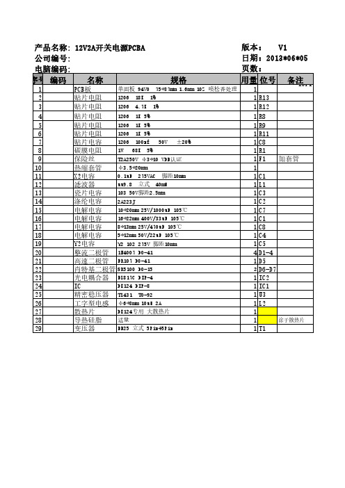
1 2 3 4 5 6 7 8 9 10 11 12 13 14 15 16 17 18 19 20 21 22 23 24 25 26 27 28 29
规格
单面板 94V0 75*37mm 1.6mm 1OZ 喷松香处理 PCB板 1206 18K 1% 贴片电阻 1206 4.7K 1% 贴片电阻 1206 1K 5% 贴片电阻 1206 1K 5% 贴片电阻 1206 1K 5% 贴片电阻 1206 100nf 50V ±20% 贴片电容 1W 68K 5% 碳膜电阻 T2A250V φ3*10 VDE认证 保险丝 φ3.5*20mm 热缩套管 0.1uF 275VAC 脚距10mm X2电容 uu9.8 立式 40mH 滤波器 103 50V脚距2.5mm 瓷片电容 2A223J 涤纶电容 10*20mm 25V/1000uF 105℃ 电解电容 16*22mm 400V/33uF 105℃ 电解电容 8*13mm 25V/470uF 105℃ 电解电容 5*12mm 50V/22uF 105℃ 电解电容 Y2 102 275V 脚距10mm Y2电容 整流二极管 1N4007 DO-41 高速二极管 FR107 DO-41 肖特基二极管 SR5100 DO-15 光电耦合器 EL817C DIP-4 DK124 DIP-8 IC 精密稳压器 TL431 TO-92 工字型电感 φ6*8mm 10uH 2A DK124专用 大散热片 散热片 适量 导热硅脂 EE25 立式 5Pin+5Pin 变压器
版本: V1 日期:2013*06*05 页数: 用量 位号 备注 1OF1
1 1 R13 1 R12 1 R8 1 R9 1 R11 1 C8 1 R1 1 F1 加套管 1 1 C1 1 L1 1 C3 1 C2 1 C7 1 C1 1 C8 1 C4 C5 4 D1-4 1 D5 2 D6-D7 1 IC2 1 IC1 1 U3 1 L2 1 涂于散热片 1 1 T1
松下12V--24AH电池技术参数
10.2V 99.3 78.2 63.0 44.3 36.8 26.5 19.6 15.2 9.60 8.51 6.11 4.84 3.94 3.36 2.17 1.21 0.993
10.5V 88.3 70.1 58.4 41.2 34.9 25.9 19.3 14.9 9.40 8.21 6.01 4.80 3.90 3.32 2.16 1.20 0.990
(hour)
放电时间
松下蓄电池(沈阳)有限公司
电话:(024)25818921 传真:(024)25818910
Website:
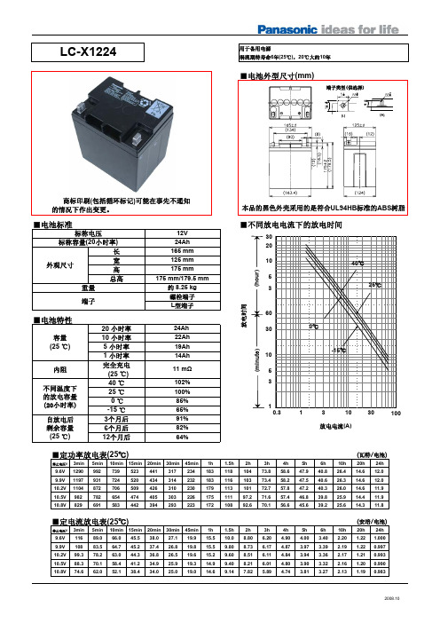
LC-X1224
用于备用电源 涓流期待寿命6年(25℃),20℃大约10年
■电池外型尺寸(mm)
端子类型(供选择)
16 M5
M5
16.5 9.8
商标印刷(包括循环标记)可能在事先不通知 的情况下作出变更。
■电池标准
标称电压
标称容量(20小时率)
长
外观尺寸
宽 高
总高
重量
端子
12V 24Ah 165 mm 125 mm 175 mm 175 mm/179.5 mm 约 8.25 kg 螺栓端子 L型端子
(瓦特/电池)
1.5h 2h
3h
4h
5h
6h 10h 20h 24h
118 104 73.8 58.6 47.9 40.8 26.4 14.6 12.0
116 103 73.4 58.2 47.5 40.6 26.3 14.6 12.0
113 101 72.7 57.8 47.2 40.3 26.0 14.6 11.9
本品的黑色外壳采用的是符合UL94HB标准的ABS树脂
■不同放电电流下的放电时间
小功率充电器电源适配器样品承认书

样品承认书SPECIFICATION FOR APPROVAL客户名称(MESSRS):产品名称(MESSRS):产品型号(MODEL NO):总页数(NO OF PAGE):版本号(REV):日期(DATE):XXXXX电子厂地址(ADD):电话(TEL):传真(FAX):邮编(P.C):XXXXXX电子厂1.总则本产品为交直流开关电源转换器,它能连续输出15 W 的直流电压源提供给负载。
本产品适用于VCD/ DVD播放机的电源供应器。
2电气性能2.1输入特性2.1.1.1电压a.额定电压范围:100—240VACb.最大电压范围:85—264VAC2.1.1.2频率频率范围:47—63 HZ2.1.1.3电流最大输入电流:0.5A(输入电压100VAC,满载输出)2.1.1.4 冷态冲击电流25℃环境气温,输入电压为240V,满载输出时的冷态冲击电流:〈25A〉2.1.1.5 功率因数功率因数:>0.5(110V交流输入电压、最大输出负载时测量,测量时要求输入电源的内阻小于0.1欧姆)2.1.1.6 效率在额定输入电压范围内>70%2.2 输出特性2.2.1.1 电压a电压1:+3.3VDCb电压2:+5VDCc电压3:+12VDCd电压4:-12VDCe电压5:-21VDCf电压6:F1~F2 5VDC2.2.1.2 电流a电流1:800mAb电流2:1000mAc电流3:200mAd电流4:200mAe电流5:100mAf电流6:100mA2.2.1.3负载调整率a.+3.3VDC:10%b.+5VDC:10%c.+12VDC:10%d.-12VDC:10%e.-21%VDC:10%f.F1~F2:10%2.2.1.4功率最大输出功率:15W2.2.1.5纹波杂讯测量时在输出端并联一个0.1微法陶瓷电容和10微法电解电容.a.+3.3VDC:<50mVb.+5VDC:<50mVc.+12VDC:<120mVd.-12VDC:<120mVe.-21VDC:<210mVf.F1~F2:<100mV2.2.1.6输出保护本产品有输出短路保护功能,故障清除后能自动恢复正常工作状态。
富士通不间断在线电源供应(UPS)电源保护数据表说明书

Data SheetFUJITSU Uninterruptible Online Power Supply (UPS) Power ProtectionPower supply protection for systems and data – powerful andreliable (APC SURT Gen2)Fujitsu Technology Solutions UPS devices ensure high-performance power supply protection for systems and data, and thus provide reliable protection against power failure, currentfluctuations and electrical interference. Fujitsu Technology Solutions offers both line interactive and online devices. Capacities of up to 10kVA provide the right power supply and technology for all individual requirements.The use of uninterruptible power supplies can particularly benefit your company from a financial viewpoint: Having to search for and restore lost or damaged data after a power failure can cost a great deal of time and money. In such incidents UPS helps to protect your data.Uninterruptible Online Power Supply (UPS) Fujitsu Technology Solutions VFI (Voltage and Frequency Independent) online UPS devices from APC are the only UPS devices to offer protection against all kinds of faults, such as power failures, frequency fluctuations, voltage swings and peaks as well as low voltage and surges. They also have precise frequency and voltage regulation as well as the Smart Slot interface for integration into SNMP-based network management. Another outstanding feature is the ability to replace used or faulty batteries during ongoing operation without any interruption. All these APC UPS devices can be converted for installation in racks / towers.Fujitsu Technology Solutions not only offerscustomers a 3-year manufacturer’s warranty (door to door) on the UPS and the batteries, but also optimal integration of the control software into the network management solution ServerView Suite. Support of Windows / Linux and SOLARIS operating systems as well as virtualization layers is provided. In contrast to the VI (Voltage Independent) line interactive and VFD (Voltage and Frequency Dependent) offline versions, the output frequency of the VFI UPS devices is totally independent of any mains, voltage and frequency changes. The mains voltage is permanently rectified in order to then be inverted back to alternating voltage. Hence the rectifierinverter combination, which achieves a constant power supply and a high filter effect. The VFI UPSdevices also have a parallel bypass switch whichcompensates for overloads in problem situations.Technical detailsTechnical detailsPY Online UPS 10kVA /10kWPY Online UPS 3kVA / 2,7W PY Online UPS 5kVA / 4,5kW PY Online UPS 8kVA / 8kWInput voltage220V - 240V 1-phase380V - 415V 3-phase 220V - 240V 1-phase220V - 240V 1-phase380V - 415V 3-phaseInput frequency50Hz / 60Hz Output voltage230 VUPS Slots 1 smart card slot (free)Input connections Hardwire 3-wire (1Ph+N+G)Hardwire 3-wire (2Ph+G)Hardwire 5-wire (3Ph+N+G)Dual Input for bypassing feature Hardwire 3-wire (1Ph+N+G)Hardwire 3-wire (1Ph+N+G)Hardwire 3-wire (2Ph+G)Hardwire 5-wire (3Ph+N+G)Dual Input for bypassingfeatureUPS Notes Integrated SNMP WEB management interface (Serial interface is not supported) APC SW, cable and manuals Interfaces Integrated WEB management interfaceHigh Resolution Graphical LCD displayOutput connections SOG #1: 6x IEC 320 C13 (10A)SOG #2: 2x IEC 320 C19 (16A)SOG #3: 2x IEC 320 C19 (16A)MOG HW 3-Wire (L+N+G)SOG #1: 6x IEC 320 C13(10A)SOG #2: 4x IEC 320 C19(16A)SOG #1: 6x IEC 320 C13(10A)SOG #2: 2x IEC 320 C19(16A)SOG #3: 2x IEC 320 C19(16A)MOG HW 3-Wire (L+N+G)Output connection notes Switched Outlet Group(s) : Ability to control a group of output load receptacles independent from the main UPSInput protection80A 1-phase (and L1 respectively)25A 3-phase (L2 / L3)32A 1-phase63A 1-phase (and L1respectively)20A 3-phase (L2 / L3)UPS Battery Pack External runtime extensionfor APC Online (VFI) UPS- 5 kVA (3U rack version);Size (HxWxD) / Weight 130 x432 x 640 mm / 80 kg- 8 to 10 kVA (3U rackversion); Size (HxWxD) /Weight 30 x 432 x 640 mm/ 80 kg- Cable to connect UPS andextension battery are partof the delivery External runtime extensionfor APC Online (VFI) UPS- 3 kVA (2U rack version);Size (HxWxD) / Weight yyy xyyy x yyy mm / yy kg- 5 kVA (3U rack version);Size (HxWxD) / Weight 130 x432 x 640 mm / 80 kg- 8 to 10 kVA (3U rackversion); Size (HxWxD) /Weight 30 x 432 x 640 mm/ 80 kg- Cable to connect UPS andextension battery are partof the deliveryExternal runtime extension for APC Online (VFI) UPS- 5 kVA (3U rack version); Size (HxWxD) / Weight 130 x 432x 640 mm / 80 kg- 8 to 10 kVA (3U rack version); Size (HxWxD) / Weight 30 x432 x 640 mm / 80 kg- Cable to connect UPS and extension battery are part ofthe deliveryBattery runtime half load11.5 min11.8 min14.8 min Battery runtime full load 3.8 min 4 min 5.3 min Weight112 kg55 kg112 kgOperating systemCertified or supported operating systemsand virtualization softwareSoftware Support PowerChute Network Shutdown (for more detailed information please look at the software support matrix on the“APC by Schneider Electric” website)Order code Product NameA3C40178823PY Online UPS S2 3kVA R/TOrder code Product NameA3C40178825PY Online UPS 5kVA R/TA3C40178826PY Online UPS 8kVA R/TA3C40178827PY Online UPS 10kVA R/TApprovals & Conformity (Standards)Europe CEGlobal CBCompliance link https:///sites/certificatesWarrantyWarranty period 3 years (depending on country)Warranty type Door-to-Door Exchange ServiceProduct Support - the perfect extensionSupport Pack Options Globally available in major metropolitan areas:9x5, Next Business Day Onsite Response Time9x5, 4h Onsite Response Time (depending on country)24x7, 4h Onsite Response Time (depending on country) Recommended Service-Service Weblink https:///emeia/support/ContactFujitsu LIMITED Website: 2023-09-02 WW-ENworldwide project for reducing burdens on the environment.Using our global know-how, we aim to contribute to the creation of a sustainable environment for future generations through IT.Please find further information at http://www./global/about/environmenttechnical specification with the maximum selection of components for the named system and not the detailed scope ofdelivery. The scope of delivery is defined by the selection of components at the time of ordering. The product was developed for normal business use.Technical data is subject to modification and delivery subject to availability. Any liability that the data and illustrations are complete, actual or correct is excluded. Designations may be trademarks and/or copyrights of the respective owner, the use of which by third parties for their own purposes may infringe the rights of such owner.More informationAll rights reserved, including intellectual property rights. Designations may be trademarks and/or copyrights of therespective owner, the use of which by third parties for their own purposes may infringe the rights of such owner. For further information see https:///global/about/resources/terms/ Copyright 2023 Fujitsu LIMITED。
Power Supply 规格及测试技术介绍
SPS (Switching Power Supply )規格及測試技規格及測試技术术介紹制作制作::肖仁军时间时间::2003年5月1日PCEG DMD R&DSME主要內容簡介一.開關電源的发展史二.開關電源的組成及原理三.開關電源的相關規格介紹内容和設備開關電源的評測内四.開關電源的評測五.開關電源Update主要內容Switch Power Supply IntroduceProduct Specifications:•Electrical Specification 電氣規格•Mechanical Specification 機械規格•Environmental Specification環境規格•EMC Specification 電磁兼容規格•Reliability Specification可靠度規格•Safety Specification安全規格ATATXATX 12VATX 12V LN1.3P o w e r S u p p l y D e v e l o p m e n tTimeSFX12V 2.3TFX 12V 1.2Power Supply DevelopmentPC機電源在286到早期的586是AT電源。
AT電源共有四路輸出(+5V、-5V、+12V、-12V),另外還向主板提供一個P.G信號AT: 6Pin+6PinAT ATX ATX 12V ATX 12V LN ,SFX12V,TFX12V 根據PC主板架构主板架构變化變化Power Connector 電源接頭一般PC 電源的接頭有下列幾種:z連接到主機板上的接頭. 由二條六腳的接頭所組成.z連接到硬碟機和光碟機的接頭. 由四腳所組成.z連接到軟碟機的接頭. 由四腳所組成但比上個接頭較小. 整個電源供應器之接線如下:( 取材自DELL )接到主機板的接頭實際圖片如下:而接到硬碟機和光碟機的實際圖片如下:Power Connector 電源接頭Power Connector 電源接頭各個接頭的定義Power Connector 電源接頭線的顏色定義訊號名稱顏色gnd接地黑色+5+5V紅色-5-5V白色+12+12V黃色-12-12V藍色`pwr good power good橙色*power good 為high 表示電源供應器已經可以提供穩定的電壓. 系統使用此訊號來作reset 的動作.當電源供應器的電壓低於某值時( 一般為4.75V ) power good 即為low. 此時系統即保持在reset 的狀態下. 如此可防止系統誤動作.Power Supply DevelopmentATX: 20PinIntel 在1997年推出的ATX Array電源標準,它主要增加了3.3V和+5VSB兩路輸出電壓和一個PS-ON信號。
JP型户外综合配电箱说明书

农网智能配变终端功能规范和技术条件
Q/GDW 11221
低压综合配电箱选型技术原则和检测技术规范
GB 14048.2-2008 低压开关设备和控制设备 第 2 部分 断路器
GB6829-2008
剩余电流动作保护电器的一般要求
GB13955-2005
剩余电流动作保护装置安装和运行
DL/T 499
农村低压电力技术规程
配、控制、保护、无功补偿、电能计量等多种功能,同时可根据用户需求加入漏电保护功能。产品具有结
构新颖、合理、防护等级高、安装调试、维护及检修方便等优点。
二、实用的标准:
IEC439-1
低压成套开关设备和控制设备
GB7251.12-2013 低压成套开关设备和控制设备 第 2 部分:成套电力开关和控制设备
动的地方。 4.5、安装位置:与地面垂直的倾斜度不超过 5º 4.6、抗震能力:地面水平加速度:2.5m/s²,地面垂直加速度:1.25m/s²,安全系数 1.67。 4.7、爬电比距:2.5cm/kV。
五、技术参数: 5.1、额定工作电压:400V 额定绝缘电压:660V。 5.2、额定频率:50Hz。 5.3、额定电流:100A~1600A。 5.4、补偿方式:三相补偿和单相补偿相结合。 5.5、补偿容量:420kvar~5kvar。 5.6、补偿方式:循环投切,编码投切,模糊控制自动投切。 5.7、最快响应时间:≤20ms。 5.8、配网供电方式:低压三相四线,可缺相运行。 5.9、防护等级:IP44。
产品说明书
户 外 综 合 配 电 箱
(JP 型)
产品说明书
湖南长高成套电器有限公司
产品说明书
JP 型户外综合配电箱
一、产品概述:
QTJP06V25-15 电源模块 产品说明书

QTJP06V25-15电源模块产品说明书深圳青铜剑科技股份有限公司地址:深圳市南山区高新区南区南环路29号留学生创业大厦二期22楼邮编:518057电话:*************传真:*************网址:邮箱:******************产品概述QTJP06V25-15是一款单通道输出的具有高绝缘特性的DC/DC电源模块,最高可为6.5kV 电压等级的IGBT驱动器供电,适配于我司开发的1QP0635V45-HiPak驱动器,或者其它相同电压供电的驱动产品。
图1 QTJP06V25-XX电源模块特点应用◆电气绝缘可达15kVac◆机车牵引◆爬电距离60mm◆轨道供电◆输出功率6W◆工业传动◆无电解电容◆高压直流输电◆使用寿命长◆柔性交流输电系统◆原副边耦合电容9.2pF◆中压变频器机械尺寸图2 机械尺寸图(单位:mm)输入输出连接器图3 端子示意图名称符号附注端子型号IN +原边输入电源正TP381H-00F-2P,思科赛德-原边输入电源地OUT VCC副边输出电源正TP381H-00F-3P,思科赛德NC空脚GND副边输出电源地电气特性参数附注最小值典型值最大值单位输入电压范围1430V空载输入电流15V13mA 24V19满载输入电流15V494mA 24V301电源欠压保护阈值8V 电源欠压恢复阈值9V 输出功率6W输出电压范围0~6W24.82525.2V内部电容输出100uF绝缘耐压原边对副边50Hz/1min15kVac爬电距离注160mm电气间隙注152mm耦合电容原副边之间注29.2pF工作温度-40+85℃储存温度-40+85℃注:1)输入输出端子之间或者输入输出端子分别与模块安装面的距离。
紧固螺钉未计算在内。
2)结构电容,LCR数字电桥测得,频率100kHz,电平0.1V。
特性曲线图4 效率Vs输入电压(满载)图5 效率Vs输出功率(Vin=15V)图6 效率Vs输出功率(Vin=24V)。
62012p-100-50说明书
62012p-100-50说明书
一、电感性负载应用
可当开关直流电源供应器时或者是改变输出电压时,电感性负载会引起反方向感应电动势影响直流电源供应器的工作,甚至会导致直流电源供应器的损坏,这个时候,在直流电源供应器的输出端与负载之间串联一只二极管,并且在负载端并联一只功率电阻和一只电容器组成的RC吸收电路,能够有效保护直流电源供应器。
二、电池类负载应用
但是可编程直流电源供应器对电池类负载充电应用时,为了避免误接电池的极性导致电源供应器的损坏,应在电源供应器与电池之间串接二极管,以保护流电源供应器的安全使用。
三、会引起反向电流的负载应用
如果连接在可编程直流电源供应器输出端的电机突然刹车时,会引起很大的反向电流,由于可编程直流电源供应器不能吸收从负载端引起的反向电流,因而输出电压会上升,解决方法是在直流电源供应器的输出端与负载之间串联一只二极管,并在负载端并接一泻放电阻来吸收反向电流,当反向电流为一尖峰突波时,请在负载两端并接一个大容量电解电容。
四、脉冲类负载应用
可脉冲类负载的电流峰值即使在直流电源供应器输出额定电流
值范围内,或者是脉冲类电路或电动机驱动电路负载电流波形,在计量设备所指示的标称值(平均值)内,电流也会达到直流电源供应器额定电流区域,从而使输出电压下降或者是显得不稳定,解决方法是在电源供应器与负载之间串接电感器,或者是选择输出电流更大的可编程直流电源供应器。
- 1、下载文档前请自行甄别文档内容的完整性,平台不提供额外的编辑、内容补充、找答案等附加服务。
- 2、"仅部分预览"的文档,不可在线预览部分如存在完整性等问题,可反馈申请退款(可完整预览的文档不适用该条件!)。
- 3、如文档侵犯您的权益,请联系客服反馈,我们会尽快为您处理(人工客服工作时间:9:00-18:30)。
产品规格书
一.适用范围
1、本电源为电子仪器、安防器材、仪表等产品而设计。
二.使用环境
1、工作温度:0~45℃
2、贮运温度:-20~65℃
3、相对温度:≤90%
三.电气特性
1、大气压力:70—106KPA。
四.输入特性
1、交流输入电压范围:100V AC~240V AC;输入电源频率:50~60Hz 。
2、最大输入电流:在输入电压额定值的下限时,最大输入电流小于600mA。
五.高压测试:
1、测试电压:1000V。
2、测试时间:3秒。
3、漏电流≤5mA。
六.输出特性
1、输出电压:空载电压DC12.0-12.60V。
2、负载电压: DC11.40-12.00V(带24欧50W电阻,电流2000mA)。
3、负载调整率正负0.8%
3、1、输出电流:0~2000mA。
3、2、输出电压过冲:<5%。
3、3、输出纹波:<250mV-P。
4、输出保护功能:输出过电流保护电路能保证本产品在过电流状态下不会坏。
4、1、输出短路保护:输出短路保护电器能保证本产品在短时间短路状态下不
会坏,故障排除后能自动恢复正常工作。
5、输出功率: 24W
6、输出极性:内正外负
七.浪涌电流
1、通电瞬间浪涌电流≤30A。
八.漏电流
1、充电对地漏电流(0.3mA)。
漏电流(1.5mA)
九.起机时间
1、电源从通电瞬间到输出电路正常工作的时间小于2秒。
十.可靠性试验
1、电老化试验:
每个产品,在标称电压220V,负载电流2000mA通电4小时,满足品质指标。
2、耳听测试:
要求输入电压在100-240V范围内,输出电压从短路(0V)到开路电压的情况下,离电源适配器1米处听不到噪音。
3、插拔测试:
设定输入电压220V,要求负载24欧/50W,连续插拔100次,间隔时间为0.5S,实验后,符合品质要求指标。
4、振动试验:
每个产品,组成包装后,在振动台上以三个方向,频率从10~50Hz加速度为1g,振动30分钟后,检测产品特性符合要求指标。
5、温、湿度试验:
每一批次抽取其30%作温度试验,首次将其中的1%置于温度为-25℃,+70℃,湿度为90%RH下进行储存试验分别1小时,恢复常温试验,指标符合要求。
如有不合格新产品,加倍重复试验,再有不合格产品,此批产品不得出厂。
6、老化过程中检测产品温升、电压、电流,发同有异常的,应拿出来分析维修。
7、冲撞,跌落测试:
每个产品从100cm高处在自由落体到坚硬的硬木地板上一次,电特性满足公司指定的品质要求。
8、弯折测试:
在输出线一端加200克负载,另一端固定情况下,为每分钟30、60°角度摆动1000次,不发生破损现象。
9、拉力测试:
固定一端,在另一端加20牛顿,五秒以后,连接处及线都无破损。
10、线路调整率正负0.5%
十一、半成品测试
1、空载测试:
将装好元件的半成品板放入测试夹具体夹稳,打开电源开关(AC~220V),测输出端V+、V-空载电压12.00V-12.60V。
2、带载测试:
接上负载(24欧50W水泥电阻),测试输出电流I2=2000mA,测试输出端V2=11.40-12.00V 纹波电压<250mV-P,输出端短路电流要小于2000mA,。
十二、安全绝缘电阻测试
1、施加300V直流电压进行测试,带电部件和输出电路及壳体之间的绝缘电阻
不低于7M欧姆,输出电路和壳体之间的绝缘电阻应不供低于2M欧姆。
十三、外观测试
1、电源适配器输入、输出插头及连接线与充电器应可靠连接,承受10N拉力,
无松动及脱落,连接头要装正,与产品配全良好。
2、电源适配器要与产品配合良好。
3、摇动电源适配器时无异响。
4、标贴贴正、贴平。
5、输出功率: 24W
十四、材料检验
1、用于本电源适配器的外壳、外形,零部件、整件,都必须经过公司质量认定
部门出具体认定证书。
2、外供厂商与本公司的合作协议,主要包括质量保证条款。
3、双出线
4、DC线材:DC头5.5*2.1 0.5 M( 内正外负)
5、AC线材: 0.5 M
十五、外观要求
1、外壳:JP-02690*50*28MM
2、外壳颜色,表面平整光滑,无刮痕、毛刺及机械损伤,外露五金
无锈蚀,氧化等现象。
十六、外壳材料
1、外壳材料为ABS原料。
十七、
1、白盒包装
十八、附则
1、本规范将根据客户需要,及时通过程序,修改调整以满足用户不断提高的新
要求.。