广州科思通光纤测温系统安装指导手册
微热通信快速安装指南说明书
M I C R O T H E R M O T E C H N O L O G I E S™MT Alliance – DT-EEPR QuickSetup GuideDocument No. 72-MTA-1025-R0.5No part of this publication may be reproduced,stored in a retrieval system, or transmitted, in anyform or by any means, electronic, mechanical,photocopying, recording, or otherwise, withoutthe prior written permission of Micro ThermoTechnologies.© 1997-2015 by Micro Thermo Technologies.All rights reserved worldwide.Local Phone: (450) 668-3033 | Fax: (450)668-2695Toll Free Canada: 1-888-664-1406 | Toll Free USA: 1-888-920-6284/micro-thermoTABLE OF CONTENTS1. Introduction (1)2. Refrigeration Configuration (1)3. Hardware Installation (1)4. Control of EEPR Valves (2)5. Set Up of RefUnits (6)6. EEPR Control of RefUnits (8)7. Defrosts (10)7.1 Circuits Controlling more than One EEPR Valve (10)8. Valve Control, Set Point (11)9. Historical Data (11)10. Process Page (12)10.1 Details of the Process (13)11. Trendgraphs (13)12. Environmental Corrections (14)13. Valve Replacement and Other Repairs (15)13.1 What to do After a Repair (15)1.IntroductionIn this Quick Set Up Guide, you will find a step-by-step procedure to set up temperature control ofrefrigerated units using EEPR (Electric Evaporator Pressure Regulator) valves and the DT-EEPR6-valve Controller (Micro Thermo part number 950-636C).The DT-EEPR (Dual Temperature) controller issupported in Alliance v. 5.2 or later.2.Refrigeration ConfigurationSet up the rack, condenser, suction groups and cir-cuits, using the Refrigeration Configuration Tool(RefSysConfig.exe). Specify an Electronic EPR as theEEPR Control Actuator for the Refrigeration Cycle. Creat-ing the rack and entering a number for its first Circuitis the minimum required to obtain the View in Alli-ance.3.Hardware Installation1.On the controller, connect the earth ground (1 or 2), the EEPR valves (3) and the network (4).2.Power up the controller (24V AC) using the connector identified as AC1-AC2 (5).–The +5V green LED (6) lights up immediately.–The “Factory” red LED (7) and “SA” (Stand Alone) green LED (8) light up if the controller has never been used.–On outputs without valves, the LED (9) blinks very briefly (drive searching for a valve.)–On outputs with a valve, the LED blinks while the valve moves during its initialization, then remains ON. It takes about 4 minutes for 6 Sporlan valves to get initialized and positioned. The valves are positioned at half their total number of steps, if the board is in Factory condition. If the board was used previously, each valve returns to where it used to be during refrigeration. Warning : overloading transformers will result in overheating and may cause a fire. A DT-EEPR controller requires 2.1 amperes when driving Sporlan valves, and 3.4 amperes for Alco valves. A100VA, 24V transformer drives only two DT-EEPR boards with Sporlan valves, for example.4. Control of EEPR ValvesAfter this section is completed, you will be able to use the Plug-In to set EEPR valves to any desired value of %Open.1. Drop a node in Alliance (10), choosing the proposed version of Refrig Dual Temp EEPR (11).2.Click on the new node’s button (12) and, in the Details Page, give it a significant name, such as LT-EEPR1 (meaning the first Low-Temperature DT-EEPR node.) 3.Go to the Commands/Status Page and click on the Install button (13). Install the node by pressing the Service Button on the board itself, or by Manual Entry (14) of its node ID (sticker on the board.)– Loading the node software takes about 2 minutes. Each valve then gets reinitialized and positioned at its Stand Alone Position (50% of the number of steps, for a board that has Factory status.)10111413121617154.Drop a plug-in (15). Just to keep things simple, identify it by the same name as the node (16).Select the Dual Temp EEPR (17).Suggestion: The Rack’s Viewis usually a convenient loca-tion (18) to drop the plug-in.185.Open the plug-in, by clicking on its button.– “Stand-Alone Mode ON ” warnings (19) appear. In Stand-Alone mode, the node positions the valves according to the best of its knowledge, then waits for further instructions.6. In the Node Configuration box, specify the ValveSeries (20-21) (ex. Sporlan CDS).192019217.Open the Valve Config page (22).– Yellow “Detected” dots (23) indicate the outputs that presently have valves connected to them. 8. Specify the valve models (24)(ex. CDS-9).– Note : CDS-16 (angle) and CDS-17 (in-line) valves are in-terchangeable, as far as control is concerned.The Start Up feature may now beused on any valves that require im-mediate positioning :9. Click on the Start Up button(25). Enter the desired valve’s %Open (percentage of open-ing) (26) and click OK.10. At the bottom left corner of the Valve Config page, select the Rack in which the DT-EEPR isinstalled (27).11. Select the refrigerant (28).– Refrigerants are managed by the EEPR systems independently of RefSysConfig. Different names may be used for the same refrigerant, such as R507 in the EEPR and its alias, AZ50, in RefSysConfig.23242233262512. Click Apply.– The “Stand-Alone” warning disappears.– The “SA” (8) and the “Factory” (7) LEDs are now both OFF (the board being configured). – The valves get Initialized and positioned one by one, which takes about 4 minutes for 6 Sporlan valves.13. Open the Process page (29).– The valves are not yet assigned (30) to any RefUnit. – The valves are in StartUp mode (31).– Valves have reached their Start Up position, the default being 50%Open.– Actual values of %Open are shown (32), that may differ slightly from the requested values, such as 19,8% instead of a requested 20%. They are at the closest available step.– Valves can be repositioned at any time by changing the Start-Up (25) value in the Valve Config page and clicking Apply.– An Internal Schedule (33) for Off Time defrost is available immediately.Overrides (34) could be used to position valves, but defrosts are not supported in Override mode. The Start Up mode (with or without Off Time defrosts) enables you to start refrigeration even be-fore RefUnits and Circuits are configured, if the need arises.5. Set Up of RefUnits1. Complete the set up of the rack in RefSysConfig, if applicable. In order to use the EEPR valves for automatic temperature control, the refrigerated units (cases, walk-ins or open areas) must be represented by a software object called “RefUnit”, that is configured by a plug-in.2. Drop a RefUnit (35) plug-in for each refrigerated unit in the MainView.293031323436 3735A RefUnit can be used to represent a single case, or a row of identical, contiguous cases. In the above figure, for example, the installer uses the same RefUnit to represent the 3 cases (assuming that they are on the same EEPR valve). He could also drop an Auxiliary RefUnit (36) to represent the case on the left hand side, and a another one (37) for the case on the right hand side.3.Set up the RefUnits in Alliance, according to the RefUnit Quick Set Up Guide.Note : it is recommended to use RefUnits for all refrigerated units, including those that are not con-trolled by an EEPR valve.38For the EEPR valve to appear (38) in the Process page of the RefUnit, it must have been declared in the Control page of the RefUnit’s plug-in.In the DT-EEPR environment, RefUnits and valves are set up inde-pendently of one another, and in any order. When a RefUnit and its valve are both configured, temperature control and monitoring is achieved by one click of the mouse. This association is done in the DT-EEPR plug-in, as described below.6.EEPR Control of RefUnits1.Open the DT-EEPR plug-in at the Valve Config page.2.Select the Primary RefUnit (39) served by each EEPR valve.3.At the bottom of the Valve Config page, click in one of the two yel-low boxes (40) to confirm the default value of the suction pressureset point.The value suggested by the plug-in comes from the set point in the SPC. If it is not available, or if you wish to use a different value, simply enter the pressure or its equivalent saturated temperature.A DT-EEPR node supports two Suction Groups. If the RefUnits are not all on the same Suction Group, you will be asked to confirm (or provide) two suction pressure set points.–Any Dual Use or Clean switch defined in the RefUnits appears in the Available Features (41) panel. 394041There may be more than one control temperature sensor, associated with an EEPR valve. This usual-ly happens :• when a RefUnit includes more than one evaporator, each evaporator hav-ing its own temperature sensor. This is illustrated as Sys20 on Page 7, where one RefUnit includes three 5-door cases,• or when the EEPR valve controls Auxiliary RefUnits in addition to its Primary RefUnit, as illustrated above with Sys20a-b-c.In the figure on top of this page, Sys20b is the Primary RefUnit, Sys20a and Sys20c are auxiliary units. Each has its own temperature sensor that must con-tribute to the control.When you pick a Primary RefUnit that is linked to more than one control tem-perature sensor, the RefUnitDetails button (42) in the DT-EEPR Plug-In turns yellow, indicating that some input is required on your part.4. Click on the RefUnitDetails button (42).5. Select any availablecalculation block (43). 6. Set the operator (44)to Average, for low temperature applica-tions, and to Mini-mum for medium temperature applica-tions.Sys20a Sys20b Sys20c4243447. DefrostsDefrost parameters are accessed through the Valve Config Page, that has one button (45) for de-frosts controlled by a Circuit, and another button (46) for Internal Defrosts.In a typical supermarket, most defrosts are controlled by a Circuit of an MT-CKT node, and are done with the EEPR valve closed. In that case, you may not have to do anything, since the RefUnit already knows its Circuit.1. For valves with defrosts controlled by a Circuit node, open Circuit Defrost Details. Enter thedesired valve %Open for Pump Down, Active Defrost (47) and Drip.For Dual Temp cases using a CDS-9 EEPR valve, a 40%Open value is suggested for hot gas defrost through the valve. Opening the valve fully will take more time and not significantly increase the flow. 2. For valves with Internal Defrost, edit the schedule (48).Internal Defrosts are done off-time, by simply closing the EEPR valve. The schedule for Internal Defrosts is internal to the EEPR node and, in version 5.2 of Alliance, it is not yet integrated within the rack’s defrost schedule.7.1 Circuits Controlling more than One EEPR ValveWhen several EEPR valves are associated with a given Circuit for defrost, the DT-EEPR Plug-In automatically creates all the necessary bindings, so that defrost only starts after all the EEPR valves have been properly positioned. No intervention is required on the part of the user.45 474949488. Valve Control, Set Point– A warning (50) may appear in the Valve Control tab if the strategy seems inappropriate. This happens, for example, if the set point is within medium temperatures and the Strate-gy is set for frozen food.1. Click on the Details button (51) to open Strategy Detailsdialog box.The refrigeration Strategy determines how a RefUnit will be treated. Fresh meat, for example, will not load shed as readily as juice, and its temperature will be regulated more closely.2. Select the Strategy (52) that seems the most appropriate forthe type of merchandise.If you uncheck the Show All Strategies check box (53), you will see only those strategies which are compatible with the particular context of this RefUnit.3. Uncheck the Use from Primary RefUnit box (54) if youwish to set the temperature set point . Enter the desired value. For DualTemp RefUnits, two values are needed.If you leave this box (54) checked, the Optimal Value from the Alarm Set will be used as the set point. It will then be easier for the store personnel to modify it. It is assumed that the store per-sonnel have access to the RefUnits, but that they do not see the DT-EEPR plug-in. 4. Click Apply.– The DT-EEPR plug-in does all the bindings for you and sends the configuration to the node. – Temperature regulation begins.9. Historical DataYou may have been asked to select Historical Data. Even then, you need to do the following step. 1. Open the History page (55).2. Select all the data that you wish to log. Any unchecked network variable will not get logged, andyou will not be able to display it in Trendgraphs.50505154535255You may click on the Factory Default button to select automatically those network variables that are usually considered as the most important.10. Process Page1.Go to the Process tab and observe the following. – The names of the Primary RefUnits (56).– A thermometer indicating, for each valve, the Active Temperature Set Point (57), as well as the Instant (58) and Average (59) temperatures.– A banner (60) reveals any special valve status or activity (Defrost, Power Off, Override, etc). – Another banner (61) may show “Marginal” or the more severe “Conflict” warning. Conflict means that the valve is likely to run 100%Open all the time. Marginal means that the set point may be maintained, but not under extreme environmental conditions. In the case of Sys21 illus-trated above, a larger valve should have been used.– The actual %Open (62) of the valve is shown, with some visual indications (63) of its opening or closing (circles of decreasing or of increasing diameter.) A button is provided to force an Override (64).Note that the icon that represents a walk-in (room or open area) (65) is different from the icon rep-resenting a case.– Observe that the valves move as needed to maintain temperature, unless the circuit is undergo-ing a defrost. One move per minute is typical.After the valve has been in service for some time, a visual indication of the status of the control is displayed. A green circle means success. A red diamong (66) means that control could be improvedby tuning. A red square indicates that some intervention is probably needed.565758596061626364656610.1 Details of the Process1.Click on the buttons, at the bottom of the Process page, to access some additional information and trendgraphs. The bottom part of the Process page provides the following infor-mation :– the Active Set Point (67) (Set 1 or Set 2, for Dual Temp RefUnits only),– the EEPR control temperature, calculated from all the sensors involved, and referred to as “Instant Temperature” (68), – its running average (69), calculated over the last 15 minutes, – the accumulated Integral temperature error (70),– a button (71) that resets both the accumulated Integral and Long Term errors,– the location (72) of the Control Temperature Sensor in the Pri-mary RefUnit (normally Discharge Air for a case and Return Air for a room).The “Trend” button (73) opens a set of preselected trendgraphs for this RefUnit, and the “Less” button (74) hides the details.11. TrendgraphsThe underlined text contains hyperlinks to Trendgraph. If you click on Instant, for example, the Trendgraph for the (instant) EEPR Control Temperature opens. Prepackaged Trendgraphs are avail-able :1. Click on the “Trend” button to open the prepackaged Trendgraph for a RefUnit. –A new window opens, similar to the one below.7312. Environmental CorrectionsTo predict the valve %Open, the controller needs three environmental variables : the temperature and humidity around the case, and the temperature of the liquid refrigerant. These three environ-mental variables can affect the calculated flow of refrigerant by more than a factor of 2.The valve %Open is obtained from the calculated flow and pressure drop. PID corrections are then applied to obtain the final valve position. If the environmental corrections are not provided, the cal-culated value will be inaccurate, and the PID corrections will be used up to compensate. As a result, they won’t be available to compensate for other disturbances, and the site will become more vulner-able.With the DT-EEPR, setting up the Environmental Corrections takes only a minute. It is done as follows.1.The Space Temperature (75) is normally taken from the temperature sensor, inside the super-market, that is closest to the case or walk-in.2. For Space Humidity, any sensor inside the store, that provides Relative Humidity (76), can beused.3. Liquid Temperature is normally obtained from one of the nodes. nvoDlt (77) from the Con-denser node (Drop Leg Temperature) is a good candidate in some cases. If the rack is equipped with subcooling, the temperature of the liquid at the output of the subcooler is a better choice.– The indication of missing binding (78) disappears as its source is speci-fied.4. If, for some reason, you don’t have access to all three environmentalcorrections (liquid temperature not available, for example), provide those that you can. It will help.5. If an environmental correction becomes erratic (sensor malfunction, forexample) you can disable it by unchecking its box (79) in the Valve Ad-vanced Page. This can also be done to avoid getting the missing binding warning, if you were unable to provide the correction.7675777913. Valve Replacement andOther RepairsBecause the valve’s coils are induc-tive, unplugging a powered valve causes sparks that may disturb or, under extreme conditions, damage a controller.It is not necessary to power down the whole controller, in order to replace a valve. An individual drive can be powered off as follows. 1. Click on the Current Valuesbutton (80), to open the Cur-rent Values window. 2. Select the valve (81). 3. Click on Power Off.– The drive is powered Off. The valve will maintain its mechani-cal position until its drive is powered On again.– A Power On button replaces the Power Off button.– A Power Off banner appears in the Process page, reminding you that the drive is Off.– The Power Off condition also appears on top of the Valve Config page.13.1 What to do After a Repair1.Check that the valve is connected. If the drive is powered Off, you need to turn it back On, using the Power On (82) button in the Current Val-ues window.If the process has been running erratically for more than 30 minutes, it may be preferable to flush the accumulated errors. This is because the errors that were accumulated during the malfunction are not relevant to the present situ-ation. This is done as follows.2. Open the Process Page. If the More button appears, click on it to revealthe details. Then click on the Error Reset button (71)(83). – The Acc Errors value (84) goes to 0 after several seconds.8081828384Revisions HistoryCreation CB 08-Dec-060.1 Document0.1 Revision CC 31-Jan-07 0.2 More “Visual” version CB 09-Mar-07revision RL 20-Apr-070.3 Footer0.4 Logo and address changed RL 14-Dec-11。
广州科思通光纤测温系统安装指导手册

感温光纤安装指导规范广州市科思通技术有限公司二○一二年十二月目录第一章感温光缆介绍. 11. 1 感温光缆简介 1第二章安装准备22. 1 施工组织. 22. 2 施工培训 2第三章感温光缆的安装.隧道空间测温感温光缆敷设要求 3在电缆桥架上的安装: 5在输煤皮带、煤粉仓等设备上的安装 6 在变压器上的安装 7在油罐等设备上的安装7第四章系统调试 8注意事项 8温度测试 8第一章感温光纤介绍1. 1 感温光缆简介由广州科思通研制开发的感温光纤(铠装,耐高温,特制)采用最高等级多模光纤纤芯,根据实际应用场合配置相应光纤紧套包层,并增加不锈钢保护管和抗拉钢丝网等铠装层保护光纤不受损害;外护套为高性能的阻燃材料,具有优良的热传导特性、机械性能、防水性能及抗腐蚀特性。
1:纤芯(Φmμ)2:涂覆层(Φ125mμ)3:阻燃聚氯乙烯护套(Φmm)4:聚酰胺纤维5:螺旋金属护套(Φmm)6:钢丝编织护套(Φmm)7:阻燃聚氯乙烯护套(Φmm)第二章安装准备2. 1 施工组织施工前应拟定详细施工计划,选派优秀项目经理主管工程施工,保证人员的配置,确定施工流程,做好人员分工,要责任到人,以保证施工顺利进行。
由于光缆非常脆弱,施工过程中有诸多注意事项,一旦中途更换施工管理人员和施工人员就会造成注意事项的遗忘和前期施工经验的丢失,所以一定要选派固定的、专职的管理人员进行施工组织和统一指挥,若必须更换施工成员,则必须先培训后上岗!2. 2 施工培训施工前需对施工人员进行施工培训和技术交底,施工全过程都要以“安全第一,质量第二,速度第三”为原则,施工过程中应尽量避免更换施工人员,如果有人员变动应及时对其进行培训。
培训至少应包括以下内容:进入施工场所要戴安全帽,高空作业要系安全带,不许吸烟 光纤易碎易断,不得让其受到锐利的或是表面粗糙的物体的割划,磨擦,碰撞,挤压;不能踩踏,折弯,强拉硬拽光纤 光缆接头由陶瓷制成,安装过程中严禁抛掷、摔打,严禁与金属、地板、墙壁等坚硬物体发生碰撞在拐弯处、穿孔处要特别注意并采取措施保护光缆施工过程中如果有与原设计不符之处或是改动设计之处均应随时记录下来,并最终在系统竣工图上体现施工完毕应将施工现场打扫干净,倒垃圾前要检查是否有工具材料混入其中第三章感温光缆的安装光缆脆弱,极易被折断、踩断,故而我方强烈要求在安装与日后维护的过程中对光缆要特别小心爱护:不能用超过 150 度的物体与其接触或是加热,例如打火机,电烙铁等;不能踩踏,折弯,强拉硬拽光缆。
测温门调试安装指导书
测温门安装使用作业指导书(4G网络版本)
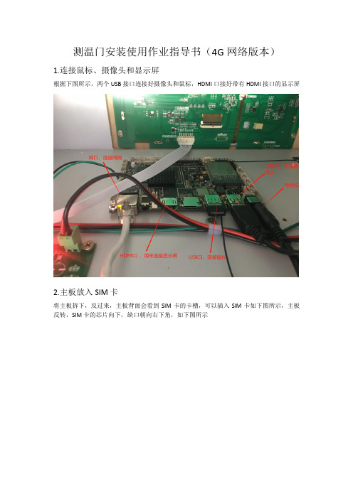
1.连接鼠标、摄像头和显示屏
根据下图所示,两个USB接口连接好摄像头和鼠标,HDMI口接好带有HDMI接口的显示屏
2.主板放入SIM卡
将主板拆下,反过来,主板背面会看到SIM卡的卡槽,可以插入SIM卡如下图所示,主板反转,SIM卡的芯片向下,缺口朝向右下角,如下图所示
3.连接显示屏安装app
(1)先将接摄像头的USB拔出,将SN号码生成app:SerialTools(3).apk以及测温软件:CeWen3288A_V1.0.0--1.apk ,考入U盘;USB口接U盘。
(2)先连接好HDMI接口的显示屏,再将测温门和显示屏上电;显示屏会进入一个安卓界面,如下图:
用鼠标上滑界面,出现下图;点击资源管理器,在找到USB 即U盘,安装上两个软件
4.生成SN号
打开生成SN号的工具,进入界面如下图提示输入密码:123456
输入完密码进入界面后,下滑选择型号712T.点击生成SN号码,即可生成SN号码;生成的SN号码可用于智慧防疫云平台添加设备
5.测温软件
如下图,安装好测温软件,打开后勾选左上角两个选项:实时温度数据;实时抓拍数据;装好摄像头后会显示相机启动成功。
(只勾选左上角两个地方;其他不动)
此时在测温门测量体温,外接的显示屏会有抓拍照片。
6.登陆卡尔防疫云平台添加设备及查看数据
区域设备管理->选择要添加设备的区域->增加
设备序列号处填写:设备的SN号;设备类型选择:体温采集设备;子系统选择:智慧防疫云平台
智慧防疫->测温数据统计->选择时间段,可以查看上报的温度和抓拍的照片。
分布式测温光纤系统使用手册
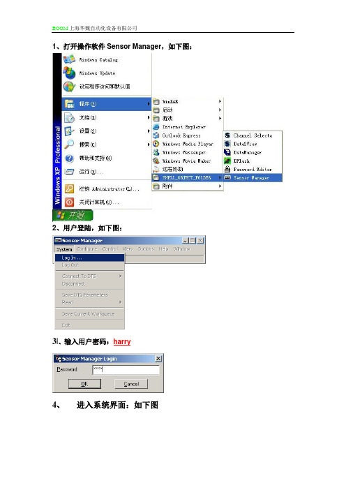
1、打开操作软件Sensor Manager,如下图:2、用户登陆,如下图:3|、输入用户密码:harry4、进入系统界面:如下图5、点击VIEW,打开状态STATUS窗口,如下图:6、点击VIEW,打开MESSAGE窗口,如下图:7、点击VIEW,打开COMMAND窗口,如下图:8、 几个窗口都打开后,点击CONNECT TO DTS ,选择DTS800(ARCNET )选项,如下图:9、 当软件和DTS800连接上后,MESSAGE 出现一长串信息,状态窗口显示现在DTS 的扫描状态。
原始状态下,DTS 是停机状态。
见下图: 10、此时在COMMAND 窗口内输入长度清零程序RFL FBR=并且点击鼠标右键并且发送(SEND )见下图:11、RFL FBR=12、点击START AND MEASUREMENTS 窗口,出现如下窗口:点击select all选项选择所有通道,点击control选择下面的Start Measurements 启动测量,点击Apply提交。
此时DTS开始运行。
13、点击control按钮下的TURN profiles on And Off,此时调出显示模块,我们会发现原始状态只选择显示6个通道的NTS曲线,通过NTS曲线我们可以得到每个通道的实际光纤长度。
14、此时我们可以把NTS曲线放大点击 +2按钮对其光缆末端进行标注,可以看到光缆实际长度,并且在标注光缆长度的时候一定要注意最好是把坐标放在光纤末端NTS信号开始比较陡下降的地方,并且记录每个通道的光纤实际长度如下图:15、点击点击START AND MEASUREMENTS 窗口,出现如下窗口:点击select all选项选择所有通道,点击control选择下面的Stop Measurements 启动测量,点击Apply提交。
此时DTS停止运行。
16、将各通道光纤长度记录后,将下面程序中的每个通道的光纤长度按照NTS图象中测得的长度修改后:将下面程序修改后复制到COMMAND窗口并且发送:*For Single-ended measurement WRI MCN,FBR=,TCP=SE1 WRI MCN,FBR=,LCS=EST* Reset fibre length (if length has previously been setup) RFL FBR=* Set Fibre lengthWRI MCL,FBR=FIBRE2,FMF=XXXX.XX,SMF=0.0 WRI MCL,FBR=FIBRE3,FMF=XXXX.XX,SMF=0.0 WRI MCL,FBR=FIBRE4,FMF=XXXX.XX,SMF=0.0 WRI MCL,FBR=FIBRE5,FMF=XXXX.XX,SMF=0.0 WRI MCL,FBR=FIBRE6,FMF=XXXX.XX,SMF=0.017、将以上长度设置程序发送进DTS 后,点击点击START AND MEASUREMENTS 窗口,出现如下窗口:此处按照实际通道的光缆NTS 测得的长度填写。
科思通_____感温光纤火灾预警系统软件手册

线型光纤感温火灾探测系统软件手册广州市科思通技术有限公司2013年5月目录一、软件安装1、安装条件2、FPGA驱动安装步骤3、测温软件安装步骤二、软件界面1、软件界面布局2、软件界面说明三、软件设置及功能1、通讯参数2、光纤参数3、调试参数4、用户管理5、运行参数6、报警参数7、报警点段8、配置点表9、网络配置10、数据查寻11、相关测试一、软件安装1、安装条件操作系统: Microsoft Windows XP 硬盘: 1G或以上剩余磁盘空间CUP: Intel PIII或赛扬800以上内存: 1G或以上USB:3个或以上COM串口: 3个或以上RJ45网口: 1个或以上2、FPGA驱动安装1、双击EZ-USB_devtools_version_261700.exe文件,运行安装软件,弹出“提取文件”页面3、弹出了询问是否接受许可协议,按“Yes”,4、弹出了选择安装的选项,选择“Custom”,按“Next”,5、弹出了安装类型页面,选择第3项,按“Next”,6、弹出了选择安装组件页面,选择图中勾的3项,按“Next”,7、弹出了安装进度页面,8、弹出了安装完成页面,按“Finish”。
3、测温软件安装步骤1.双击FHDS XV1.0.0.exe(具体看版本号)文件,运行安装软件,弹出安装程序欢迎画面2.点击“下一步”,安装继续进行,弹出选择程序安装路径3.点击“下一步”,安装继续进行,弹出选择桌面快捷方式的画面4.点击“下一步”,安装继续进行,弹出准备安装画面5.点击“安装”,安装继续进行,弹出正在安装的画面6.等待一段时间后,弹出安装完成的画面二、软件界面1、软件界面布局2、软件界面说明1.先点击“启动联机”按钮,成功后才点击“开始采样”按钮,两个按钮之间切换点击频率不能太快。
2.“温度曲线”、“原始曲线”、“电子地图”三种显示状态,在同一个按钮进行相互切换。
以下是温度曲线与原始曲线对应情况。
光纤测温系统说明电子教案

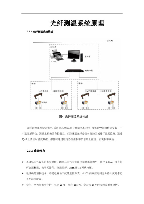
光纤测温系统说明光纤测温系统原理2.3.1光纤测温系统构成图4 光纤测温系统构成光纤测温系统设计说明:采用点式测温,由于解调体积较小,可每台**每组件近安装一个温度解调仪,测温主机安装在控制室,多路感温光纤分别对监控区域进行温度监测,通过RJ45上传实时温度数据,报警时通过继电器输出报警信息给上位机,实现报警联动。
2.3.2系统特点➢不降低电气设备的安全等级:测温式电气火灾监控探测器体积小,直径2.8mm,没有任何金属材质、电子元器件,绝缘性好,20cm耐10万伏电压。
➢最准确的预报技术:不受电磁场干扰的监测方式,≤10S的响应时间充分将火灾隐患消灭在萌芽阶段。
➢全年、全天侯安全守护:至少25年,每年365天,全天候24小时实时监测和分析。
➢高性价比:初期造价经济合理,后期运行免维护。
➢减少了监测盲区、提高了设备安全性:定位精度1mm。
➢节省成本:直接安装于温升部位,实时记录、显示监测点数据,实现无人值守监测站目标。
➢建立了维修依据:全面掌握设备运行情况,可以预测、预知设备老化,从而根据设备运营状况提出检修时间、检修计划。
➢智能判断性:能够对被测对象的正常温度、异常温度、火灾进行快速的判断和分析。
➢参数设置的方便性:可设置多级的预报警、报警阀值;报警方式有声、光、不同颜色的图形界面、继电器输出等形式。
可在任何时间准确显示任何一点监测的温度,在事故发生前早期预警。
➢网络性:该系统具有开放式、网络化、单元化及组态方便等优点,以实现信息化的管理。
➢兼容性:系统可以通过RS232/RS485、RJ45、内置继电器等输出形式与消防报警系统,提供信号进行声、光报警,信号输出准确、完整。
➢安全性:具有多级权限设置功能,授权管理,确保系统的安全。
➢数据管理性:能够对不同类型的数据进行统计、保存、查询、打印、复制。
数据类型有:一级预报警数据;二级预报警数据,事故报警数据,异常数据,正常数据,日/月/年平均数据,火情分析数据等。
光纤测温传感器安装指南
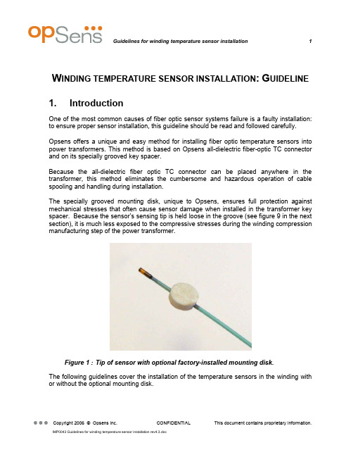
W INDING TEMPERATURE SENSOR INSTALLATION:G UIDELINE 1. IntroductionOne of the most common causes of fiber optic sensor systems failure is a faulty installation: to ensure proper sensor installation, this guideline should be read and followed carefully.Opsens offers a unique and easy method for installing fiber optic temperature sensors into power transformers. This method is based on Opsens all-dielectric fiber-optic TC connector and on its specially grooved key spacer.Because the all-dielectric fiber optic TC connector can be placed anywhere in the transformer, this method eliminates the cumbersome and hazardous operation of cable spooling and handling during installation.The specially grooved mounting disk, unique to Opsens, ensures full protection against mechanical stresses that often cause sensor damage when installed in the transformer key spacer. Because the sensor’s sensing tip is held loose in the groove (see figure 9 in the next section), it is much less exposed to the compressive stresses during the winding compression manufacturing step of the power transformer.Figure 1 : Tip of sensor with optional factory-installed mounting disk.The following guidelines cover the installation of the temperature sensors in the winding with or without the optional mounting disk.2. General overview of the TC connectivity solutionThe following figure shows the all dielectric TC connection schematic.Figure 2 : Overview of sensor installation in transformer tank showing theTC connectivity solution. Since the TC connection can be placed anywhere in the transformer, only short fiber optic cable lengh is needed: this avoids conveying and handling long spans of fiber-optic cable during sensor installation and reduces the chances of sensor damage.The following figures (3, 4 &5) show a typical installation in the power transformer winding.Figure 3 : Sensor installation.To the sensorFigure 4 : Typical TC connector installation:Figure 5 : Internal extension cable routing:3. Installing a standard sensorThis section gives some advice for installing a standard sensor (without the optional mounting disk) into a key spacer.The customer must prepare his own key spacers for installing the fiber optic sensor. A groove and two openings have to be made in the spacer. Figure 6 shows the recommended groove.appliedFigure 6 : Specifications to user for grooving a key spacer for a standardsensor.Opsens fiber optic protection tube has tiny venting holes to let air escape and let oil in. A first hole is located 38mm from the tip of the sensor. Do not let adhesive go into the hole: the hard adhesive can transfer too much stress on the optical fiber.Do not let adhesive go onto the tip either: during coil compression, a hard adhesive will transfer directly the pressure from the coil to the sensor tip. Make sure the sensor tip is snug but free to move inside the groove.Referring to Figure 6: the glue will spread along the groove by capillarity. Drill two holes approx 4-5 mm to stop the capillary action and to keep the glue from reaching either the tip or the first hole.The groove is kept tight at the tip to maximize heat transfer.The angle of the groove is chosen to ensure a smooth egress of the fiber optic cable so that there is no sharp turn in the fibre cable (minimum bending radius is 25 mm for 62.5 / 125 µm fiber).Do not let the sensor tip be crushed when compressing the coil. Minimum spacer thickness is 1.5 mm to give headroom for the 1.2 mm O.D. sensor tip. Example : for a 15 % coil compression ratio, using 1.6 mm thick spacer and the 1.2 mm O.D. sensor tip, the maximum allowable compression is (1.6 – 1.2) ÷ 1.6 =25 % which gives some tolerance to local variations and irregularities.4. Installing a sensor equipped with the optionalmounting diskAs an option to the regular sensor, Opsens can provide sensors with a factory-installed mounting disc at 12mm from the sensor tip.The customer must prepare its own key spacers for installing the fiber optic sensor. A groove and an opening have to be made in the spacer.Figure 7 : Example of a grooved key spacer.Figure 8 : Specifications to user for grooving a key spacer for a sensorequipped with the optional mounting disk.The fiber optic temperature sensors provided by Opsens can be ordered with a mounting disc. This disc, mounted of the sensor fiber-optic cable, is inserted into the round opening of the grooved key spacer as shown on figure 9. Since the disc is held tight into the opening,there is no need for using adhesive. Epoxy or white glue can be used though to facilitate handling of the spacer/sensor assembly during insertion in the winding. The disk is 2 mm thick, so the minimum spacer thickness must also be 2 mm.The following figures show the assembly procedures of the fiber optic sensor into the grooved key spacer.Figure 9 : Installation steps for sensor equipped with optional mountingdisk.5.Installing into the transformer windingFigure 10 shows the sensor installation schematic into the transformer’s windings.Mounting discSensor tip1234installation:y Avoid sharp radius turns with the fiber-optic cable.y Respect specified minimum bending radius for the sensor and cable : 18 mm for 62.5/125 µm fiber (25 mm preferable).y Avoid tensioning or twisting the fiber-optic cabley Avoid pinch points and “scissors” when setting the sensors in placey Do not pull on fiber-optic cable to clear tangles; carefully unwind insteady Avoid dropping or scraping fiber-optic connectors on hard surfacesy Keep the surface of the fiber-optic connector very, very cleany Use the supplied fiber optic connector cleaner liberally, before and after each and every connection。
光纤传感系统测温技术的使用教程与精度验证
光纤传感系统测温技术的使用教程与精度验证随着科技的发展,光纤传感技术被广泛应用于各个领域,其中测温技术是最常见和重要的应用之一。
光纤传感系统测温技术是一种基于光纤传感器对温度进行测量的方法,具有高度精确和实时性强的特点。
本文将为大家详细介绍光纤传感系统测温技术的使用教程以及如何进行精度验证。
一、光纤传感系统测温技术的使用教程1. 准备工作在开始使用光纤传感系统测温技术之前,我们需要准备一些必要的设备和材料,包括测温设备、光纤传感器、信号调理器、数据采集器和计算机等。
同时,还需要事先安装好相关的软件和驱动程序。
2. 系统部署与连接将光纤传感器安装在待测温度区域,确保其与测温设备、信号调理器和数据采集器等设备连接正常。
根据光纤传感器的技术规格和使用说明书,正确连接并配置相关设备。
3. 软件设置与校准启动计算机并打开数据采集软件。
在软件界面上,进行相应的系统设置和校准操作,以确保测温系统的准确性和稳定性。
根据测温系统的要求,选择适当的工作模式和参数设置。
4. 测温操作在软件界面上,选择需要测量的传感器通道,并设置相应的温度范围和采样间隔等参数。
点击开始测量按钮后,系统将实时显示光纤传感器所测得的温度数据。
5. 数据分析与记录将测得的温度数据导出到电子表格中,并进行必要的数据分析和校正。
根据实际需求,可制作相应的温度曲线图、温度变化趋势图等。
二、光纤传感系统测温技术的精度验证光纤传感系统测温技术的精度验证是确保测温结果准确可靠的重要步骤。
1. 校准光纤传感器在进行精度验证之前,需要校准光纤传感器。
校准过程可以根据光纤传感器的使用说明书进行操作,通常包括将传感器放入已知温度环境中,测得光纤传感器输出的温度数据与实际温度进行对比校准。
2. 温度均匀性验证将光纤传感器放置在一个已知温度稳定且均匀分布的介质中,记录并分析光纤传感器所测得的温度数据。
根据实际情况,选择不同的温度范围进行验证,并比较光纤传感器测得的数据与已知温度的差异。
感温光纤测温系统操作手册课件

配置网络连接
设置正确的网络参数,确保软 件能够正常连接到服务器。
系统参数设置
根据实际需求,配置系统参数 ,如温度范围、报警阈值等。
系统调试与校准
开机自检
启动系统后,进行开机自检, 确保所有设备正常工作。
温度校准
使用标准温度计对系统进行温 度校准,确保测量准确度。
功能测试
测试系统的各项功能,如温度 实时监测、报警、数据记录等 。
定期检查设备软件更新,并按照提示 进行软件升级。
参加制造商提供的培训或在线课程, 学习新功能和操作方法。
硬件升级
根据需要,对设备的硬件进行升级, 以提高性能或兼容性。
06
安全注意事项
操作安全规范
01
操作前应仔细阅读本操 作手册,确保熟悉所有 操作步骤和注意事项。
02
操作时应穿着适当的防 护装备,如防静电工作 服、防滑鞋等,以保障 人身安全。
01
报警设置
02
根据实际需求,设置温度报警阈值。
03
可配置报警方式,如声光电等多种形式。
报警设置与处理
01
报警处理
02
03
04
当温度超过报警阈值时,触发 报警机制。
报警信息实时显示在操作界面 上。
操作人员需根据报警信息及时 处理异常情况。
数据存储与导
数据存储
01
可根据需要配置数据存储周期和存储方式 。
性能优化
根据测试结果,对系统进行必 要的性能优化和调整。
04
操作流程
开机与关机操作
开机操作 打开电源开关,确保系统供电正常。
等待系统自检完成,检查各模块是否正常工作。
开机与关机操作
确认系统无异常后,进入操作界面。 关机操作 退出操作界面,关闭系统软件。
光纤测温仪安全操作及保养规程

光纤测温仪安全操作及保养规程光纤测温仪是一种高精度、无接触、非侵入式测温仪器,被广泛应用于电力、石化、冶金、化工等领域。
由于其操作方式和使用环境的特殊性,安全操作和正确保养尤为重要。
本文将从以下几个方面介绍光纤测温仪的安全操作和保养规程。
一、安全操作规程1. 入场验收在光纤测温仪到货之后应立即进行验收,主要包括如下几个方面:1.检查设备包装是否完好。
如有破损,应做记录并及时与供应商联系解决;2.核对配件清单,确认是否全部到位。
如有遗漏,应当立即与供应商取得联系,补齐遗漏部分;3.验证设备的技术性能是否符合要求。
如有问题应及时与供应商联系,进行维修或更换。
2. 设备安装安装光纤测温仪有以下几个重要步骤:1.安装前应核实工程布置图和使用说明书,确认安装位置和方式,严格按照设备要求安装,避免误用;2.对仪器供电、信号接口和光纤接口做好标记,符合标准颜色;3.确认光纤接口是否干净,且无裂纹、损伤等情况,避免影响测量精度;4.在线路连接完毕后,切勿操作设备开关,防止给设备带来损坏;5.将设备接地保护措施落实到位,避免漏电和电脑网络干扰现象。
3. 设备操作在使用光纤测温仪时需要注意以下几个操作细节:1.避免光纤接口弯折,尤其是在导管弯曲处,可适当留下一些张力,防止产生弯曲;2.不要在设备开启过程中拉动连接线,会引起模块锁定,影响测量精度;3.定期检查系统电缆及接线端子,保证连接的可靠性;4.在设备使用完成后应切断电源,防止过电流损坏设备。
4. 常见问题处理光纤测温仪常见问题如下:•信号质量不好——应检查光纤的连接,清洁光纤的面孔,并避免光纤被弯折;•温度不稳定——对设备进行检测,检查温度采集器的传感器是否有过热、过冷、视死角等问题;•信号干扰——在使用设备时应加强静电防护,避免使用高压设备和电磁辐射较大的设备;•软件异常——可参照说明书,进行软件芯片的更换处理。
二、保养规程光纤测温仪的保养是设备能够长久、高精度运行的重要保障,下面是光纤测温仪的保养规程:1. 使用环境保养在使用光纤测温仪时应保证环境温度稳定,不出现温差过大的情况。
广州科思通光纤测温系统安装指导手册
感温光纤安装指导规范广州市科思通技术有限公司二○一二年十二月目录第一章感温光缆介绍. 11. 1 感温光缆简介 1第二章安装准备22. 1 施工组织. 22. 2 施工培训 2第三章感温光缆的安装.隧道空间测温感温光缆敷设要求 3在电缆桥架上的安装: 5在输煤皮带、煤粉仓等设备上的安装 6在变压器上的安装 7在油罐等设备上的安装7第四章系统调试 8注意事项 8温度测试 8第一章感温光纤介绍1. 1 感温光缆简介由广州科思通研制开发的感温光纤(铠装,耐高温,特制)采用最高等级多模光纤纤芯,根据实际应用场合配置相应光纤紧套包层,并增加不锈钢保护管和抗拉钢丝网等铠装层保护光纤不受损害;外护套为高性能的阻燃材料,具有优良的热传导特性、机械性能、防水性能及抗腐蚀特性。
1:纤芯(Φmμ)2:涂覆层(Φ125mμ)3:阻燃聚氯乙烯护套(Φmm)4:聚酰胺纤维5:螺旋金属护套(Φmm)6:钢丝编织护套(Φmm)7:阻燃聚氯乙烯护套(Φmm)第二章安装准备2. 1 施工组织施工前应拟定详细施工计划,选派优秀项目经理主管工程施工,保证人员的配置,确定施工流程,做好人员分工,要责任到人,以保证施工顺利进行。
由于光缆非常脆弱,施工过程中有诸多注意事项,一旦中途更换施工管理人员和施工人员就会造成注意事项的遗忘和前期施工经验的丢失,所以一定要选派固定的、专职的管理人员进行施工组织和统一指挥,若必须更换施工成员,则必须先培训后上岗!2. 2 施工培训施工前需对施工人员进行施工培训和技术交底,施工全过程都要以“安全第一,质量第二,速度第三”为原则,施工过程中应尽量避免更换施工人员,如果有人员变动应及时对其进行培训。
培训至少应包括以下内容:进入施工场所要戴安全帽,高空作业要系安全带,不许吸烟 光纤易碎易断,不得让其受到锐利的或是表面粗糙的物体的割划,磨擦,碰撞,挤压;不能踩踏,折弯,强拉硬拽光纤 光缆接头由陶瓷制成,安装过程中严禁抛掷、摔打,严禁与金属、地板、墙壁等坚硬物体发生碰撞在拐弯处、穿孔处要特别注意并采取措施保护光缆施工过程中如果有与原设计不符之处或是改动设计之处均应随时记录下来,并最终在系统竣工图上体现施工完毕应将施工现场打扫干净,倒垃圾前要检查是否有工具材料混入其中第三章感温光缆的安装光缆脆弱,极易被折断、踩断,故而我方强烈要求在安装与日后维护的过程中对光缆要特别小心爱护:不能用超过 150 度的物体与其接触或是加热,例如打火机,电烙铁等;不能踩踏,折弯,强拉硬拽光缆。
感温光纤测温系统操作手册

4.2.4.11 【电流测试】 在用户权限允许的前提下, 登录“电流测试”对话框,如下 图所示: 当没有外加电流测量设备 时,可以通过本功能模拟电流 值,方便载流量软件调试。
4.2.4.1 【通讯参数】 在用户权限允许的前提下,登录 “通讯参数”对话框如下图所 示:
和打上勾该功能有效,否则无效; 相应操作完成后,点击“保存” 按钮生效。
FORESTON
广州市科思通技术有限公司
第四章 操作说明
*4.2 软件功能介绍
4.2.4.2 【光纤参数】 在用户权限允许的前提下,登录 “光纤参数”对话框如下图所示: “ 相邻数据平均点”、“原始数据起始 点”、“光纤采样序号”、“参考温 度起始点”、“参考温度结束点”、 “光纤故障设定值”的各项对应数值 在出厂时已设定完成(注意:非生产 厂家专业技术人员勿改动);“C0”、 “Ck”对应值需由生产厂家专业技术 人员现场标定设置。 4.2.4.3 【调试参数】 在用户权限允许的前提下,登录“光纤 参数”对话框如下图所示 : 用户需要在巡检时,确认“X曲线设定”、 “ Y曲线设定”为“ 520±20”,“ X高 压设定”、“ Y 高压设定”为“ 44” , “高压/曲线”设置为“曲线”项, “激光器温度设定”值为“5”,“机内 温度滑窗数”值为“ 10”,“激光温度 滑窗数”值为“ 10”,“脉宽个数”值 为“5”,“起始数”值为“5”;“X曲 线幅度值”、“ Y 曲线幅度值”需在 “ 520±20” 范围内动态显示。如果事 实值偏离上述值,请与厂家专业技术人
7、弹出了选择安装组件页面,选择图中 勾的3项,按“Next”,
8、弹出了安装完成页面,按“Finish”
FORESTON
广州市科思通技术有限公司
第三章 安装说明
测温门调试安装指导书

测温门安装使用作业指导书(4G网络版本)
1.连接鼠标、摄像头和显示屏
根据下图所示,两个USB接口连接好摄像头和鼠标,HDMI口接好带有HDMI接口的显示屏
2.主板放入SIM卡
将主板拆下,反过来,主板背面会看到SIM卡的卡槽,可以插入SIM卡如下图所示,主板反转,SIM卡的芯片向下,缺口朝向右下角,如下图所示
3.连接显示屏安装app
(1)先将接摄像头的USB拔出,将SN号码生成app:SerialTools(3).apk以及测温软件:CeWen3288A_V1.0.0--1.apk ,考入U盘;USB口接U盘。
(2)先连接好HDMI接口的显示屏,再将测温门和显示屏上电;显示屏会进入一个安卓界面,如下图:
用鼠标上滑界面,出现下图;点击资源管理器,在找到USB 即U盘,安装上两个软件
4.生成SN号
打开生成SN号的工具,进入界面如下图提示输入密码:123456
输入完密码进入界面后,下滑选择型号712T.点击生成SN号码,即可生成SN号码;生成的SN号码可用于智慧防疫云平台添加设备
5.测温软件
如下图,安装好测温软件,打开后勾选左上角两个选项:实时温度数据;实时抓拍数据;装好摄像头后会显示相机启动成功。
(只勾选左上角两个地方;其他不动)
此时在测温门测量体温,外接的显示屏会有抓拍照片。
6.登陆卡尔防疫云平台添加设备及查看数据
区域设备管理->选择要添加设备的区域->增加
设备序列号处填写:设备的SN号;设备类型选择:体温采集设备;子系统选择:智慧防疫云平台
智慧防疫->测温数据统计->选择时间段,可以查看上报的温度和抓拍的照片。
10-光纤测温安装及其注意事项
光纤测温安装及其注意事项1引言电缆的额定载流量是按《电力电缆运行规程》的规定,基于在不同负载和状况下的热损耗计算而来的,此计算值相对比较保守,浪费了电缆的很大部分传输能力。
如果能实时监测电缆的线芯温度,就能最大限度地挖掘和提高电缆的载流量,利用现有的电缆线路输送更大的容量,并且通过对缆芯温度的监测,还可以通过温度的变化及时发现电缆运行中的缺陷,避免电力事故的发生。
而光纤测温技术是一项较为成熟的技术,目前已在许多领域得到应用,利用光纤可以实现对电缆表皮温度的监测,再根据电缆表皮温度与线芯温度之间对应关系,即可得到电缆的线芯温度。
但由于电缆制造原因,使光纤附带在电缆中的长度受到限制。
因此,光纤需与电缆一同进行附件安装。
解决电缆附件安装中光纤的连接问题直接影响到光纤测温的可行性。
2测温原理光纤测温的机理是依据背向喇曼(Raman)散射效应。
激光脉冲与光纤分子相互作用,发生散射,散射有多种,瑞利(Rayleigh)散射、布里渊(Brillouin)散射和喇曼(Raman)散射等。
其中喇曼散射是由于光纤分子的热振动,它会产生一个比光源波长长的光,称斯托克斯(Stokes)光,和一个比光源波长短的光,称为反斯托克斯(Anti-Stokes)光。
光纤受外部温度的调制使光纤中的反斯托克斯(Anti-Stokes)光强发生变化,Anti-Stokes与Stokes的比值提供了温度的绝对指示,而温度测量点的距离是通过记录背向散射光到达测试点的时间得到的,距离短的点的散射光到达早,距离远的散射光信号到达晚,通过温度和距离的计算就可以得到沿光缆各点的温度,从而生成光纤各点的温度曲线,实现对沿光纤温度场的分布式测量。
并以此作为依据,监测设备的状态和分析缺陷。
3光纤测温在电缆专业的应用光纤传感技术目前已在许多领域得到发展和应用,在电缆专业,利用光纤进行电缆温度分布监测已成为保证电缆安全运行的一项新课题。
电缆光纤测温在国外,如英国、法国、日本都已有了实用化应用。
光纤测温系统说明书
光纤测温系统原理2.3.1光纤测温系统构成图4 光纤测温系统构成光纤测温系统设计说明:采用点式测温,由于解调体积较小,可每台**每组件近安装一个温度解调仪,测温主机安装在控制室,多路感温光纤分别对监控区域进行温度监测,通过RJ45上传实时温度数据,报警时通过继电器输出报警信息给上位机,实现报警联动。
2.3.2系统特点➢不降低电气设备的安全等级:测温式电气火灾监控探测器体积小,直径2.8mm,没有任何金属材质、电子元器件,绝缘性好,20cm耐10万伏电压。
➢最准确的预报技术:不受电磁场干扰的监测方式,≤10S的响应时间充分将火灾隐患消灭在萌芽阶段。
➢全年、全天侯安全守护:至少25年,每年365天,全天候24小时实时监测和分析。
➢高性价比:初期造价经济合理,后期运行免维护。
➢减少了监测盲区、提高了设备安全性:定位精度1mm。
➢节省成本:直接安装于温升部位,实时记录、显示监测点数据,实现无人值守监测站目标。
➢建立了维修依据:全面掌握设备运行情况,可以预测、预知设备老化,从而根据设备运营状况提出检修时间、检修计划。
➢智能判断性:能够对被测对象的正常温度、异常温度、火灾进行快速的判断和分析。
➢参数设置的方便性:可设置多级的预报警、报警阀值;报警方式有声、光、不同颜色的图形界面、继电器输出等形式。
可在任何时间准确显示任何一点监测的温度,在事故发生前早期预警。
➢网络性:该系统具有开放式、网络化、单元化及组态方便等优点,以实现信息化的管理。
➢兼容性:系统可以通过RS232/RS485、RJ45、置继电器等输出形式与消防报警系统,提供信号进行声、光报警,信号输出准确、完整。
➢安全性:具有多级权限设置功能,授权管理,确保系统的安全。
➢数据管理性:能够对不同类型的数据进行统计、保存、查询、打印、复制。
数据类型有:一级预报警数据;二级预报警数据,事故报警数据,异常数据,正常数据,日/月/年平均数据,火情分析数据等。
➢远程服务性:系统具有远程诊断、远程软件升级和远程维护接口功能。
测温系统安装协议
测温系统安装协议1. 引言本文档旨在确定测温系统的安装协议,确保系统的正常、高效、安全运行。
测温系统是一种用于监测和记录环境温度的设备,广泛应用于各行各业。
本协议将详细说明系统的安装流程、要求以及相关注意事项。
2. 安装流程2.1 硬件准备在安装测温系统之前,需要准备以下硬件设备: - 测温设备 - 传感器 - 数据收集器 - 网络连接设备2.2 安装步骤2.2.1 选择合适的安装位置根据实际需要选择合适的安装位置,确保能够充分监测所需温度区域,并方便设备的维护和管理。
2.2.2 安装传感器根据测温需求,在所选安装位置安装传感器。
安装时需注意避免传感器受到外界物体遮挡或干扰。
2.2.3 安装测温设备将测温设备与传感器进行连接,确保连接牢固可靠。
同时,根据设备说明书进行相应的设置和配置。
2.2.4 安装数据收集器将数据收集器与测温设备连接,并与网络连接设备相连。
确保数据能够准确传输到数据中心或服务器。
2.2.5 联网测试对安装完成的测温系统进行联网测试,确保设备与数据中心或服务器的连接正常,并能够正确地传输和接收数据。
3. 安装要求3.1 硬件要求•测温设备需具备合适的测温范围和精度,以满足实际需要。
•传感器需与测温设备兼容,并具备稳定的数据采集能力。
•数据收集器需具备稳定的网络连接能力,以确保数据的及时传输和接收。
3.2 网络要求•测温系统需要接入稳定可靠的网络,以实现数据传输和远程监控。
•网络带宽需满足系统数据传输的需求,以避免数据传输过程中的延迟或丢失。
3.3 安装环境要求•安装位置应选择在温度变化较小的环境,以确保测温数据的准确性。
•避免安装在暴露的、易受外界干扰的位置,例如阳光直射、水源附近等。
4. 注意事项•在安装过程中,必须遵守相关安全规定和操作规程,确保人身和设备的安全。
•在安装位置选择上,需遵循相关规定和标准,以满足安全和实际需求。
•在安装完成后,需定期对系统进行维护和检查,确保设备的正常运行和数据的准确性。
光纤测温设备施工方案
光纤测温设备施工方案1. 引言光纤测温设备是一种利用光纤传感技术实现温度测量的设备。
它具有高精度、实时性强、安装方便等优点,在许多领域,如工业生产、环境监测、火灾预警等方面得到广泛应用。
本文档将详细介绍光纤测温设备的施工方案,包括设备选型、安装位置选择、布线和连接、设备调试等内容。
2. 设备选型在选择光纤测温设备时,需要考虑以下几个因素:2.1 测温范围根据实际需要测量的温度范围,选择合适的光纤测温设备。
不同类型的设备适用于不同的温度范围,一般可覆盖-200℃至+2000℃的范围。
2.2 精度要求根据实际需要的温度精度要求,选择符合要求的光纤测温设备。
一般来说,精度为0.1℃的设备能够满足大部分应用需求。
2.3 安装环境考虑光纤测温设备的安装环境,选择适合的防护等级和材质。
如果设备将安装在特殊环境中,如高温、低温、腐蚀性气体等环境,应选择具备相应耐受能力的设备。
3. 安装位置选择光纤测温设备的安装位置选择是关键的一步,它直接影响到测量结果的准确性和可靠性。
在选择安装位置时,需考虑以下几个因素:3.1 测温对象根据实际需要测温的对象,选择合适的安装位置。
一般来说,需要测温的对象表面附近是最佳安装位置。
3.2 光纤布设根据各个测温点的位置和数量,合理布设光纤。
在光纤布设过程中,应避免弯曲或拉伸过大,以免影响测量精度。
3.3 安装固定根据安装位置,选择合适的固定方式固定光纤。
光纤应牢固地固定在测温对象上,避免在使用过程中发生位移或脱落。
4. 布线和连接在施工过程中,需要进行光纤布线和连接工作。
具体步骤如下:4.1 光纤布线根据光纤的具体布设要求,合理布线。
在布线过程中,应注意避免过长的光纤或过多的连接头,尽量减小信号损耗。
4.2 连接设备使用合适的连接器连接光纤和设备。
在连接过程中,应确保连接器的质量良好,保证光纤信号的正常传输。
5. 设备调试在安装完成后,需要进行设备调试。
具体步骤如下:5.1 设备接通电源将光纤测温设备接通电源,确保设备可以正常启动。
无线测温系统安装说明

无线测温系统安装说明无线测温系统安装说明系统工作原理:无线温度传感器每分钟测量一次该监测点的运行温度,环境温度传感器也会自动测量环境温度,这些温度数据通过2.4GHz无线信道传输到基站,基站会保存、记录这些数据。
主机会定时通过CAN总线或RS-485总线轮询各基站,各基站将收到的温度数据传输到主机,主机将总线温度数据进行处理并保存。
主机通过比较设备与环境的相对温升、室内与室外大气的相对温升,分析可能的过热情况,提前发出预警信号,提醒管理人员进行处理。
主机与集控站可以通过以太网方式进行通讯,或采用自定义温度模型按IEC61850标准与主机通讯。
1、数据传输基站功用数据传输基站(图1-1)由MCU、RS-485接口、CAN接口、2.45GHz 数字RF收发器、宽输入DC/DC直流稳压电源、IP68ABS外壳和高增益定向天线等组成工作原理:2.45GHzRF收发器收到传感器发来的数据会产生中断信号,MCU立即读取该数据,进行分类处理、并保存到内存和FLASH ROM中。
在主机通过CAN或485总线查询时将收到的数据传输到主机进行处理。
图1-12、数据传输基站布设标准室内安装的基站应该选择远离带电设备、导线的墙体、立柱,同时尽可能使基站信号覆盖范围广、电磁波视线良好的地点,安装位置通常应该控制在高度为2.5~3米的位置,便于安装、调试维护。
室外安装的基站应该选择远离带电设备、导线的墙体、杆塔,同时尽可能使基站信号覆盖范围广、电磁波视线良好的地点,安装位置通常应该控制在高度为2.5~3米的位置,并尽可能选择在集控室厂房上安装,便于布线和缩短信号线的长度,以及便于安装、调试维护。
3、数据传输基站安装方法先将数据传输基站同不锈钢万向节、安装支架(图3-1左)装配起来,再把这一整体用膨胀螺丝固定到已确定好位置的墙上(图3-1右)即可。
待数据传输基站安装好后,根据无线温度传感器的分布,调整一下基站朝向,对准测量区域后就可对其进行接线。
- 1、下载文档前请自行甄别文档内容的完整性,平台不提供额外的编辑、内容补充、找答案等附加服务。
- 2、"仅部分预览"的文档,不可在线预览部分如存在完整性等问题,可反馈申请退款(可完整预览的文档不适用该条件!)。
- 3、如文档侵犯您的权益,请联系客服反馈,我们会尽快为您处理(人工客服工作时间:9:00-18:30)。
感温光纤安装指导规范
广州市科思通技术有限公司
二○一二年十二月
目录
第一章感温光缆介绍. 1
1. 1 感温光缆简介 1
第二章安装准备2
2. 1 施工组织. 2
2. 2 施工培训 2
第三章感温光缆的安装.
隧道空间测温
3.1 感温光缆敷设要求 3
3.2 在电缆桥架上的安装: 5
3.3 在输煤皮带、煤粉仓等设备上的安装 6 3.4 在变压器上的安装 7
3.5 在油罐等设备上的安装7
第四章系统调试 8
4.1 注意事项 8
4.2 温度测试 8
第一章感温光纤介绍
1. 1 感温光缆简介
由广州科思通研制开发的感温光纤(铠装,耐高温,特制)采用最高等级多模光纤纤芯,根据实际应用场合配置相应光纤紧套包层,并增加不锈钢保护管和抗拉钢丝网等铠装层保护光纤不受损害;外护套为高性能的阻燃材料,具有优良的热传导特性、机械性能、防水性能及抗腐蚀特性。
1:纤芯(Φ62.5m
μ)
2:涂覆层(Φ125m
μ)
3:阻燃聚氯乙烯护套(Φ0.9mm)
4:聚酰胺纤维
5:螺旋金属护套(Φ2.2mm)
6:钢丝编织护套(Φ2.5mm)
7:阻燃聚氯乙烯护套(Φ2.8mm)
第二章安装准备
2. 1 施工组织
施工前应拟定详细施工计划,选派优秀项目经理主管工程施工,保证人员的配置,确定施工流程,做好人员分工,要责任到人,以保证施工顺利进行。
由于光缆非常脆弱,施工过程中有诸多注意事项,一旦中途更换施工管理人员和施工人员就会造成注意事项的遗忘和前期施工经验的丢失,所以一定要选派固定的、专职的管理人员进行施工组织和统一指挥,若必须更换施工成员,则必须先培训后上岗!
2. 2 施工培训
施工前需对施工人员进行施工培训和技术交底,施工全过程都要以“安全第一,质量第二,速度第三”为原则,施工过程中应尽量避免更换施工人员,如果有人员变动应及时对其进行培训。
培训至少应包括以下内容:
进入施工场所要戴安全帽,高空作业要系安全带,不许吸烟
光纤易碎易断,不得让其受到锐利的或是表面粗糙的物体的割划,磨擦,碰撞,挤压;不能踩踏,折弯,强拉硬拽光纤
光缆接头由陶瓷制成,安装过程中严禁抛掷、摔打,严禁与金属、地板、墙壁等坚硬物体发生碰撞
在拐弯处、穿孔处要特别注意并采取措施保护光缆
施工过程中如果有与原设计不符之处或是改动设计之处均应随时记录
下来,并最终在系统竣工图上体现
施工完毕应将施工现场打扫干净,倒垃圾前要检查是否有工具材料混入其中
第三章感温光缆的安装
光缆脆弱,极易被折断、踩断,故而我方强烈要求在安装与日后维护的过程中对光缆要特别小心爱护:
不能用超过 150 度的物体与其接触或是加热,例如打火机,电烙铁等;
不能踩踏,折弯,强拉硬拽光缆。
光缆接头由陶瓷制成,接头端面稍碰即坏,安装过程中一定要保护好接
头,严禁抛掷、摔打,严禁与金属、地板、墙壁等坚硬物体发生碰撞。
3.1 感温光缆敷设要求
敷设原则:严格按照设计图纸敷设光缆,以方便日后按图准确查找报警位置和检修。
光缆编号:敷设前应对光缆进行编号(光缆两端都要贴上编号标记),以免日后多条光缆之间产生混淆。
