1835安装预算13-2
HSD ES919中文说明书

Via della Meccanica 16
Loc. Chiusa di Ginestreto
61100佩扎罗(意大利)
电话: (+39)0721.439.612
传真:(+39)0721.441.606
电子邮件: hsd.sales@hsd.it
HU
U
网址: www.2________________________________________________1/98
§ 6一般信息 ...................................................................................................................................................... 9 6.1 产品的正确使用 ................................................................................................................................. 9 6.2 制造商和部件的鉴定............................................................................................................................ 10 6.3 电主轴主要部件的描述 ..................................................................................................................... 11 6.4 词汇表 ................................................................................................................................................... 12
《公共建筑节能(绿色建筑)工程施工质量验收规范》DBJ50-234-2016
( 7 ) 本 规 范 第 16.2.10 条 依 据 国 家 标 准 《 太 阳 能 供 热 采 暖 工 程 技 术 规 范 》 GB50495-2009 第 5.3.5 条的规定。
(8)本规范第 3.4.4 条为绿色建筑工程涉及的建筑环境与资源综合利用子分部工程 验收方式的规定。
本规范由重庆市城乡建设委员会负责管理,由重庆市建设技术发展中心(重庆市建 筑节能中心)、重庆市绿色建筑技术促进中心负责具体技术内容解释。在本规范的实施 过程中,希望各单位注意收集资料,总结经验,并将需要修改、补充的意见和有关资料 交重庆市建设技术发展中心(重庆市渝中区牛角沱上清寺路 69 号 7 楼,邮编:400015, 电话:023-63601374,传真:023-63861277),以便今后修订时参考。
建设部备案号: J13144-2015
DB
重庆市工程建设标准 DBJ50-234-2016Leabharlann 公共建筑节能(绿色建筑)工程
施工质量验收规范
Code for acceptance of energy efficient public building(green building) construction
(3)本规范第 1.0.4、3.1.2、11.2.4、22.0.6、22.0.7 条内容分别依据国家标准《建 筑节能工程施工质量验收规范》GB50411-2007 第 1.0.5、3.1.2 条、11.2.3、15.0.5、15.0.5 条等强制性条文要求。
安装指南- extron fox3 sr 201 光纤缩放接收器说明书

1I M P O .e x t r o n .c o m f o r t i o ni n s t r u c ti on s ,e c t i n g t h eFOX3 SR 201 • Setup GuideThis guide provides quick start instructions for an experienced installer to set up and operate the Extron FOX3 SR 201 Fiber Opticscaling receivers. This scaling receiver scales resolutions up to 4K @ 60 Hz, 4:4:4 video, and extends with 2-CH audio, RS-232, and IR over fiber. The FOX3 SR 201 is available in either singlemode (SM) or multimode (MM) transmission mode.InstallationREMOTEPOWER 12V2.0A MAXA OUT IN BOUT INLANHDMIFOX3 SR 201RAUDIOCONTROLOUTPUTSIG F C A D H E BFigure 1.FOX3 SR 201 Rear PanelA Power Inlet F Remote RS-232B Power LED G LAN Ethernet portC Audio output H SFP module and LEDsD HDMI output I Reset buttonE Control RS-232/IR portStep 1 — MountingTurn off or disconnect all equipment power sources and mount the scaling receiver as required. For mounting details and considerations, see the FOX3 SR 201 User Guide at .Step 2 — Output Connectionsa. D ).b. C ) (see figure 2 to wire the captive screwUnbalanced Stereo OutputBalanced Stereo Output LRLRa. To pass serial, IR data, or control signals, such as for serial control of a projector,connect the master device to the transmitter and the controlled device to thereceiver via the CONTROL 5-pole captive screw connector (see E and figure 3 for wiring).Figure 3. RS-232 and IR Wiring2FOX3 SR 201 • Setup Guide (Continued)b. For remote control of a unit and loading firmware (LAN or USB only), connect a host device, such as a computer or controlsystem, to one of the following ports (see the FOX3 SR 201 User Guide , available at , for details):•Remote RS-232 port — Connect the 3-pole captive screw connector to this port (F ). The protocol for the Remote port is as follows:• 9600 baud • no parity • 8 data bits • 1 stop bit • no flow control• LAN Ethernet port — Connect an RJ-45 connector to this port (G ).•USB Configuration port — Connect a USB mini-B connector to this port (see figure 5, B on page 2).Step 4 — Throughput Connections).b. to the transmitter, connect a cable between the A Out port on the receiver and A In port on the transmitter (2).c. To transmit an uncompressed 4K @ 60 Hz signal, using the Uncompressed Video LinkLicense,repeat step 4a on the SFP B port on the scaling receiver SFP Link LEDs — ReceiverFigure 4.Fiber Cable Connection• Transmit Optical OUT LED — Lights solid green when powered and lights off when there is no power on the endpoint.•Receive Optical IN LED — Lights solid green when light is present and lights off when there is no power or light present.Step 5 — Power ConnectionConnect the included external 12 VDC power supply into the 2-pole connector (see figure 1, A on page 1). The power LED lights (B ) when the unit is receiving power.OperationAfter the receiver, transmitter, and their connected devices are powered up, the system is fully operational. If any problems are encountered, verify that the cables are routed and connected properly and the display device has a compatible resolution and refresh rate. If problems persist, call the Extron S3 Sales & Technical Support Hotline (see the contact number on page 6).FOX3 SR 201MENUINPUTSIGNAL HDCPENTER C AD EB Figure 5.FOX3 SR 201 Front PanelA Power LED — Indicates power is applied to the unit.B USB Config port — Connect a USB Mini-B cable to a computer to configure the device and update the firmware via ProductConfiguration Software (PCS), Simple Instruction Set (SIS) commands, or internal web pages.C Input LEDs —• Signal LED — Lights when the unit detects an input video signal.•HDCP LED — Lights when the input signal is HDCP encrypted.D Menu and Enter buttons — Press these buttons to access and navigate the on-screen display menu system.E Navigation buttons — Press these buttons to navigate through the on-screen display menu system or change settings. ResetPress the rear panel recessed reset button (see figure 1, I on page 1) if the FOX3 scaling receiver firmware is corruptedor the unit gets disconnected during the update process. The different resets allow the device to revert to the factory loaded firmware, reset IP seetings, or reset configuration to default (see the Reset Modes table, for details on the reset modes).Front Panel Lockout Mode (Executive Mode)The front panel lockout mode limits operation of the device from the front panel. When enabled, use SIS commands or the Product Configuration Software (PCS) to configure the device. To enable or disable the front panel lockout mode through the front panel, press and hold the Menu (see figure 5, D on page 2) and down arrow (E) buttons simultaneously for 5 seconds oruntil the power LED blinks.34FOX3 SR 201 • Setup Guide (Continued)Configuration and ControlTo configure the FOX3 SR, use the front panel controls and the on-screen display (OSD) menu, Simple instruction Set (SIS) commands, or PCS.On-screen display menu systemThe OSD menu consists of two submenus, Device Info and Setup , that can be accessed using the front panel Menu button. View the menu on a display connected to the HDMI output connector (see figure 1, D on page 2). The Device Info submenu is view only. The following fields can be configured from the Setup submenu:•Output Rate — Select from a list of refresh rates (see Output Resolution table on page 5). The default setting is 1080p @ 60 Hz.•HDMI Format — Select the output format:• Auto (default)• DVI RGB 444• HDMI RGB 444 Full • HDMI RGB 444 Limited • HDMI YUV 444 Full • HDMI YUV 444 Limited • HDMI YUV 422 Full •HDMI YUV 422 Limited• Test Pattern — Select an available test pattern to display or turn a test pattern off. The available test pattern selections are Crop, Alternating Pixels, Crosshatch, and Color Bars. The default setting is Off.•Factory Reset — Reset the unit to its factory default values (removing any user-specified values) while retaining all TCP/IP settings.To adjust settings:1. Press the Menu button to access the main menu.2. Press the directional arrows to navigate to a desired submenu.3. Press the Enter button to access submenu items of a selected submenu.4. Press the directional arrows to navigate a desired submenu item.5. Press the Enter button to select a submenu item for adjustment.6. As required, press the directional arrows or press the Enter button to adjust submenu items.7. Press the Menu button to return to the list of submenus or exit the OSD menu.Product Configuration SoftwareThe FOX3 scaling receiver can be configured via the Product Configuration Software when it is installed on a connected host device, such as a PC, through the front panel USB port or LAN port (see the FOX3 SR 201 User Guidefor more details).Internal Web PagesTo configure the FOX3 SR 201 using the factory-installed internal web pages in a web browser, connect the LAN port on the receiver to a LAN or WAN. The default IP address is 192.168.254.254. Basic Scaler SIS CommandsUse Simple Instruction Set (SIS) commands for operation and configuration of the scaling receiver using a PC connected to:• A LAN or WAN using the rear panel RJ-45 LAN port (see figure 1, G on page 1) via an SSH client and port 22023.• The Remote RS-232 port (see figure 1, F ) via DataViewer.• The front panel USB config port (see figure 5, B on page 2) via an SSH client using IP address 203.0.113.22 and port 22023.Command and Response Table for SIS Commands*Default output resolution5668-2888-50 Rev. A04 21For information on safety guidelines, regulatory compliances, EMI/EMF compatibility, accessibility, and related topics, see the Extron Safety and Regulatory Compliance Guide on the Extron website.© 2021 Extron — All rights reserved. All trademarks mentioned are the property of their respective owners.Worldwide Headquarters: Extron USA West, 1025 E. Ball Road, Anaheim, CA 92805, 800.633.9876。
NCStudio操作手册

维宏®数控系统NCSTUDIO V5.4软件使用手册目录升级纪录............................................................................................................................ I I 目录.. (I)1概述 (1)1.1软件特性 (1)2系统安装与连接 (3)2.1N CSTUDIO™的系统基本配置 (3)计算机主机 (3)操作系统 (3)2.2N CSTUDIO™系统的安装 (4)安装Ncstudio™软件 (5)安装Ncstudio™运动控制卡 (8)重新启动计算机 (8)2.3其他安装问题 (8)2.4卸载N CSTUDIO™系统 (9)2.5N CSTUDIO™控制卡与驱动系统的连接 (10)3NCSTUDIO™基本概念 (11)3.1操作模式与状态 (11)操作模式 (11)操作状态 (12)3.2机床坐标系 (13)机械坐标系 (13)工件坐标系 (13)4NCSTUDIO™操作界面 (15)4.1标题栏 (16)4.2菜单栏 (17)4.3工具栏 (18)4.4数控信息栏 (19)4.5状态栏 (19)4.6数控状态窗口 (19)加工状态和时间信息 (20)当前位置 (20)进给速度 (21)机床控制 (22)4.7自动操作窗口 (23)4.8手动操作窗口 (25)4.9加工轨迹窗口 (28)三维视图模式 (28)上下文菜单 (31)设置个性化参数 (31)4.10系统日志窗口 (32)4.11程序管理窗口 (33)4.12系统参数窗口 (34)加工参数 (35)厂商参数 (38)4.13程序编辑窗口 (41)4.14输入输出状态(I/O状态)窗口 (42)5NCSTUDIO™菜单系统 (44)5.1“文件”菜单 (44)打开并装载 (44)卸载 (45)新建加工程序 (46)打开并编辑 (46)编辑当前加工程序 (46)保存 (46)另存为 (46)关闭 (47)最近装载的加工程序 (47)最近编辑的加工程序 (47)退出 (47)5.2“编辑”菜单 (48)5.3“查看”菜单 (49)工具栏 (50)状态栏 (50)全屏 (50)显示加工程序行号 (51)跟踪加工程序当前行 (51)加工程序信息 (52)5.4“操作”菜单 (52)单步执行 (53)设置当前点为工件原点 (53)设置当前点工件坐标 (54)回工件原点 (54)开始 (55)暂停 (56)停止 (56)进入仿真模式并开始仿真 (56)高级开始 (57)断点继续 (57)执行加工指令 (58)微调 (61)对刀 (62)回机械原点 (62)复位 (63)5.5“机床”菜单 (64)5.6“窗口”菜单 (64)5.7“帮助”菜单 (65)6操作步骤 (66)6.1开机 (66)6.2机械复位(可选) (66)6.3载入加工程序 (66)6.4手动操作 (67)6.5确定工件原点 (67)6.6执行自动加工 (68)6.7直接定位功能 (69)7操作时的注意事项 (70)7.1多任务执行注意事项 (70)7.2回机械原点注意事项 (70)8最终用户软件许可协议 .................................................... 错误!未定义书签。
理光MP9000 、Pro 1357EX 维修手册

• 空转轮。 空转轮的材料也会变为聚氨酯,以防轮子向打印的纸张转印条纹。 双面单元 • 传送轮。 传送轮的颜色由黑色变为灰色,以防在打印件上留下脏污图像和轮子轨迹。 • 驱动轮、空转轮。 聚氨酯材料用于其中一些驱动轮和空转轮,以防纸张潮湿和高温导致 轮子膨胀。 (之前机器中的膨胀轮子冷却之后不会恢复为正常尺寸。) • 导板。 聚酯片覆盖了导板的整个表面以改善纸张传送。 控制 • 线速度。 为了改善大尺寸纸张的 PPM,通过缩短纸张之间的间隙,送入较大尺寸时线速 度已得以提高。
• 之前机器的清洁网单元可在新机器中安装,但产量更低。 若在 D059 中安装了 D101 清洁网,产量将为 650K 而非 750 K。若在 D101 中安装了 D059 清洁网单元,使用 寿命将从 24 m 延长到 27 m,但 D059 清洁网单元更昂贵。 • 清洁网单元的批号有所不同。 (D101: 绿色,D059: 黑色) • 已安装单元的批号可在 D059 而非 D101 单元上看到。 • 定影导板。 为了改善纸张传送,定影导板的形状有所变化(具有更凸形状),插槽(纸 张进入定影单元)的形状亦有所变化。 • 新防静电毛刷。 增加了防静电毛刷。 此新毛刷可释放压辊的静电,以减少静态偏差导致 的黑斑和其它问题。 纸张输出 • 传送导板。 去除了传送导板上的条带。 (此条带刮伤铜版纸并导致打印件变色,因此将 其去除。) • 更好地冷却。 为了防止露水形成,已将传送导板穿孔并增加了风扇。 • 传送轮、皮带。 传送轮和皮带的材料由黑色变为灰色。 这样可防止在打印纸张上留下脏 污图像和轮子轨迹。 • 驱动轮。 聚氨酯用于其中一些驱动轮,以防纸张潮湿和高温导致轮子膨胀。 (之前机器 中的膨胀轮子冷却之后不会恢复为正常尺寸。) 7
1. 拆卸或组装机器及外围设备的部件之前,确保已拔下插头。 2. 插头应靠近机器,且易于使用。 3. 请注意,即使主电源开关关闭,机器和纸盘单元的某些部件仍带有电压。 4. 主开关开启时,在外部盖板关闭或打开的情况下若要执行任何调整或运行检查,双手应 远离电气或机械驱动的部件。 5. 机器完成预热期([启动]键开始闪烁红色和绿色)之前若按下[启动]键,双手应远离机械 和电气部件,因为预热期一旦完成,机器即开始复印。 6. 机器运行期间,定影单元的内部及金属部件变得极热。 注意避免用手触碰此类部件。 7. 务必将电源线直接连接至墙壁插座。 切勿使用延长线。 8. 检查电源线是否损坏。 切勿切割电源线或尝试以任何方式改装。 9. 保持机器远离灰尘和高湿场所。 切勿将机器暴露于腐蚀气体。 10. 切勿在机器周围使用易燃气体或气溶胶。 11. 切勿用湿手操作电源线或插头。
智能化工程供货安装方案

智能化工程供货安装方案目录1. 智能化工程供货安装方案总纲 (3)1.1 方案概述 (4)1.2 项目背景与目标 (5)1.3 方案设计依据 (6)1.4 方案组织结构与分工 (7)2. 智能化工程供货安装方案 (8)2.1 工程概况 (9)2.1.1 工程项目基本信息 (9)2.1.2 工程项目范围 (10)2.1.3 工程项目特点 (11)2.2 供货计划 (13)2.3 安装计划 (13)2.3.1 安装工序安排 (15)2.3.2 安装人员配置 (15)2.3.3 安装技术要求 (16)2.3.4 安装进度监控 (17)2.4 施工准备 (18)2.4.1 施工现场准备 (20)2.4.2 施工机械配置 (21)2.4.3 施工材料准备工作 (22)2.4.4 施工应急预案 (23)2.5 施工流程 (24)2.5.1 智能化设备的安装 (25)2.5.2 布线与线缆敷设 (26)2.5.3 系统调试与验收 (27)2.6 质量控制与保证 (29)2.6.1 质量管理组织 (30)2.6.2 质量控制措施 (31)2.6.3 质量监督检查 (32)2.6.4 质量事故处理 (34)2.7 安全管理 (35)2.7.1 安全管理体系 (36)2.7.2 施工安全措施 (37)2.7.3 安全应急预案 (39)2.7.4 安全教育与培训 (40)2.8 环保与职业健康 (41)2.8.1 环境保护措施 (43)2.8.2 职业健康安全管理 (44)2.8.3 环境卫生监控 (45)2.9 成本控制与预算管理 (47)2.9.1 成本控制目标 (47)2.9.2 成本预算编制 (48)2.9.3 成本动态控制 (50)2.9.4 成本分析与反馈 (51)2.10 风险评估与应对 (53)2.10.1 风险评估方法 (55)2.10.2 风险源分析 (56)2.10.3 风险预防措施 (58)2.10.4 风险应对预案 (59)3. 附件与参考资料 (61)3.1 工程图纸与技术规范 (61)3.2 供货与安装计划表格 (62)3.3 质量控制与安全管理记录表 (64)3.4 成本预算明细表 (64)3.5 风险评估与应对记录表 (65)1. 智能化工程供货安装方案总纲供货安装目标:明确智能化工程供货安装的目标和预期效果,如提高效率、满足安全要求等。
航盛维修手册统一版

www. hangsheng- sh. com
3.3.2.3 车内部半球摄像头................................................................28 3.3.2.3.1 车内部半球摄像头参数.....................................................28 3.3.2.3.2 车内部半球摄像头尺寸图.................................................28 3.3.2.3.3 车内部半球摄像头接口定义.............................................29 3.3.3 连接线参数 .............................................................................. 29 3.3.4 控制盒尺寸 .............................................................................. 29 3.3.5 系统连接总成图....................................................................... 29 3.4 故障排除指导 ..................................................................................... 30 3.5 注意事项 ............................................................................................ 30 影音类 ............................................................................................................... 31 4 高清播放器(固态存储).......................................................................... 31 4.1 功能描述 ............................................................................................. 31 4.2 系统组成 ............................................................................................. 31 4.2.1 产品图示 .................................................................................. 31 4.2.2 系统组成图 .............................................................................. 32 4.2.3 整机接线图 .............................................................................. 32 4.3 技术参数 ............................................................................................. 33 4.3.1 性能及技术参数....................................................................... 33 4.3.2 面板及定义 .............................................................................. 33 4.4 故障排除及维护指导.......................................................................... 34 4.4.1 故障排除 ................................................................................. 34 4.4.2 日常维护保养.......................................................................... 34 5 液晶显示器 ................................................................................................. 35 5.1 功能描述 ............................................................................................. 35 5.1.1 功能介绍:.............................................................................. 35 5.2 系统组成 ............................................................................................. 35
VxSCADA软件工程指导手册

电击危险:标示有可能产生电击危险的信息。
4.1 系统结构.......................................................................................................................................... 3 4.1.1 调控中心............................................................................................................................... 3 4.1.2 站控系统............................................................................................................................... 4
Risk of electrical shock: Indicates information that Potential shock hazard where HAZARDOUS LIVE voltages greater than 30V RMS, 42.4V peak, or 60V DC may be accessible.
VxSCADA 软件
叨明叨哩国

震动 冲击
认证
品质认证
稳若磐石·信诫点金
稳-信
产品尺寸(单位:
工业平板电脑系列
mm)
产晶型号:
TPC-1012
①GND ②USB吃 ③USB吃 ④LAN ⑤LAN
外观尺寸: 307( 宽 )*243(高 ) *58(深)
柜体开孔: 299( 宽 )*238(高)
( COM1 :RS-232/485 ( COM2:RS-232/485 ( On/Off ( Li ne Out ( Power
COM吨(其中 COM 1 和 COM2 可 自行设置为 RS-232 或者 RS-485) COM1 和 COM2 自带 3KV 光稿隔离保护
Intel 1OM/100M/1OOOM LAW2 (硬件芯片符合 EtherCAT总线)
U SB俞4
USB Audio Mini
P C I-E 扩展
内置 802W 扬声器吃 ,
EtherC T础 A nt d. . 呵 .Y.FG •• 『。‘叩
协议支持
板载内存
压铸铝面板 , 细砂纹, IP65 防护等级 高强度钢板和铝挤材质 , 阳极氧化 , 细砂纹 所有 1/0 接 口 最用板载和无线缆方式连接,确保连接稳定可靠
整机无风扇主动式散热结构设计
无凤扇设计 硬盘安装 结构参数 安装方式
⑩ COM3/COM4 : RS-232 ⑩ 可拆卸硬盘
VESA孔距: 100( 宽)叮 OO(高)
产晶尺寸图
飞--土地中 ;2二L尹
246 , 9
+--l
IJ
'"
~
飞主写...
1 11
|川 1 1 1 1
PBD7- PBA7-系列精密台秤安装手册说明书

安装手册恭喜您选择了 METTLER TOLEDO 的品质与精密。
如果您能够依照用户手册正确使用新设备,并且由我们厂商培训的服务团队进行定期校准和维护,本设备将能可靠与精确地运行,保证您购买的产品物有所值。
如需了解按照您的需求和预算量身订制的服务协议,请联系我们。
欲知详情,请登陆/service。
为了让您购买的设备发挥最高性能,须注意下列几点:1. 注册您的产品:欢迎您在 /productregistration注册您的产品,以便我们通知您与产品有关的增强功能、更新及重要通知。
2. 如需服务,请联系 METTLER TOLEDO:量具的价值与其精确度成正比——不合规格的量具会降低品质、减少利润并增加责任风险。
METTLER TOLEDO 及时的服务能够保证精确,延长设备的运行时间及使用寿命。
–安装、配置、集成与培训:我们的服务代表均为厂商培训的称重设备专家。
我们承诺我们的称重设备能够经济并及时地生产,并且我们的员工训练有素。
–初次校准文件:每个工业秤都有其独有的安装环境及应用要求,所以需要对运行情况进行测试和验证。
我们的校准服务及验证文件精确无误,保证了生产质量,并能提供良好的系统运行记录。
–定期校准维护:校准服务协议让我们对于您的称重程序和遵守规程证明充满信心。
我们提供多样化的服务计划,专为您的需求和预算而定制。
2 PBD7- / PBA7-系列 30403591A目录1 防爆区域作业安全注意事项 (4)2 安装 (6)2.1 准备工作 (6)2.2 设置 (6)2.3 调整至水平 (7)2.4 延长并安装连接电缆 (8)2.5 危险区域中的等电位连接 (8)2.6 将秤体连接至称重仪表 (10)2.7 调试 (10)3 配置可能性 (11)3.1 通用信息 (11)3.2 原厂设定的配置数据 (12)4 装配规划 (13)4.1 规划注意事项 (13)4.2 预负荷范围 (13)4.3 安装可能性 (14)5 尺寸 (17)3 30403591A PBD7- / PBA7-系列1 防爆区域作业安全注意事项 ▲PBD7- / PBA7-系列精密台秤为 Category 3 危险区域(燃气和灰尘)提供选项。
萨奥丹佛斯柱塞泵手册
1998年发布型号
概述. ....................................................................................................................................................................................... 9 更改说明............................................................................................................................................................................... 9 壳体. ................................................................................................................................................................................. 9 补油泵. ............................................................................................................................................................................ 9 辅助安装法兰盖板. .................................................................................................................................................... 9 补油溢流阀.................................................................................................................................................................... 9 阀芯-回路冲洗.......................................................................................................................................................... 9
舒适13 固定速炉控制器 更换套件 安装说明说明书

Installation Instructions -751NOTE:Read the entire instruction manual before starting theinstallation.SAFETY CONSIDERATIONSImproper installation,adjustment,alteration,service,maintenance,or use can cause explosion,fire,electrical shock,or otherconditions which may cause death,personal injury,or propertydamage.Consult a qualified installer,service agency,or yourdistributor or branch for information or assistance.The qualifiedinstaller or agency must use factory--authorized kits or accessorieswhen modifying this product.Refer to the individual instructionspackaged with the kits or accessories when installing.Follow all safety codes.Wear safety glasses,protective clothing,and work gloves.Have a fire extinguisher available.Read theseinstructions thoroughly and follow all warnings or cautionsinclude in literature and attached to the unit.Consult local buildingcodes,the current editions of the National Fuel Gas Code(NFGC)NFPA54/ANSI Z223.1and the National Electrical Code(NEC)NFPA70.In Canada,refer to the current editions of the National Standards ofCanada CAN/CSA--B149.1and.2Natural Gas and PropaneInstallation Codes,and Canadian Electrical Code CSA C22.1.Recognize safety information.This is the safety--alertsymbol.When you see this symbol on the unit and in instructions or manuals,be alert to the potential for personal injury. Understand the signal words DANGER,WARNING,and CAUTION.These words are used with the safety--alert symbol.DANGER identifies the most serious hazards which will result in severe personal injury or death.WARNING signifies hazards which could result in personal injury or death.CAUTION is used to identify unsafe practices which may result in minor personal injury or product and property damage.NOTE is used to highlight suggestions which will result in enhanced installation,reliability,or operation.INTRODUCTIONThis kit is a direct replacement for circuit boards Part No. HK42FZ004,HK42FZ007,HK42FZ008,HK42FZ009, HK42FZ011,HK42FZ013and HK42FZ016.Changes to the operation of this control include:1.The blower off delay selections are:90,120,150and180seconds.2.A COOLING OFF DELAY DEFEAT JUMBER“J2”isprovided.It is located in the upper left corner of controlboard.See Fig.2.When cut,this permanently reduces the90second blower--off delay in the cooling mode,to5sec-onds.3.All115--volt neutrals are grouped together in one locationof board.See Fig.2.4.Humidifier connection is removed from thermostat terminalblock.It is now a1/4--in.spade terminal,next to the ther-mostat terminal block.See Fig.2.Kit Contains:Part Number Control board HK42FZ034Wire harness adapter328151-701Non-condensing furnace(80%wiring diagram)328251-101Rev.A Condensing furnace(90%wiring diagram)328218-101Rev.B Service label327596-101Rev.BTWINNINGThe control board in this kit CANNOT be twinned with any of the following circuit boards:HK42FZ004,HK42FZ007,HK42FZ008,HK42FZ009,HK42FZ011,HK42FZ016In twinned installations,another kit will be required for the twin furnace.ELECTROSTATIC DISCHARGE(ESD)1.Disconnect all power to the furnace.DO NOT TOUCHTHE CONTROL OR ANY WIRE CONNECTED TOTHE CONTROL PRIOR TO DISCHARGING YOURBODY’S ELECTROSTATIC CHARGE TO GROUND.2.Ground yourself by touching your hand and tools to clean,unpainted,metal surface of furnace close to control.3.After touching chassis,you may proceed to service thefurnace.You will recharge your body with static electricityby moving about or shuffling your feet.Reground yourself.4.If you touch ungrounded objects(recharge your body withstatic electricity),reground e this procedure forinstalled and uninstalled(ungrounded)furnaces.5.Ground yourself again before handling a new control toprotect control from damage.If control is to be installed infurnace,follow items1through5againbefore installing control.Put all used AND new controls into containers before touching ungrounded objects.6.An ESD service kit(available from commercial sources) may also be used to prevent ESD damage.INSTALLATIONStep1—Removal of Existing Control1.Turn thermostat to OFF or set temperature to the lowestsetting.2.Turn off electrical supply to furnace.3.Turn off gas supply to furnace.4.For80%furnaces remove control access and blower door.For90%furnaces remove outer door assembly and re-move the two screws from blower access panel and setaside.5.Disconnect thermostat and humidifier wires(if equipped).6.Disconnect line voltage,blower,EAC,(if equipped)andtransformer wires.7.For80%furnaces remove retaining screws and removefurnace control board from bracket.For90%furnaces re-move two screws from blower deck that hold the controlbox assembly.Lower control box assembly.Remove retain-ing screw(s)from board and remove board from controlbox assembly.8.Remove wiring harness connectors from furnace controlboard.9.Inspect control and control box for evidence of waterstaining.10.Correct any sources of water leakage(humidifier,evaporator coil,vent system)into the control area.Step2—Installing the New Control1.Ground yourself!Handle furnace control board by edges.2.Insert tab(s)of board into slots of control box(if required).3.Install furnace control board retaining screw(s).Installwiring harness adapter(part#328151--701)to threeconnections of the existing furnace wiring harness.See Fig.3.a.The furnace harness9--pin connector plugs into themating9--pin adapter harness connector.b.The furnace harness2--pin connector plugs into themating2--pin adapter harness connector.c.The furnace harness3--pin connector plugs into themating3--pin adapter harness connector.4.Connect the other end of the adapter harness(part number328151--701)to the new furnace control board.a.The11--pin connector connects to PL1on the furnacecontrol board.See Fig.2and3.b.The2--pin connector which has2black wires connectsto PL2on the furnace control board.See Fig.2and3.c.The2white wires connect to the115--volt Neutral spadeconnections,located in front of PL1on the new furnacecontrol board.See Fig.2and3.5.Connect the transformer to the new furnace control board.See Fig.2.a.Blue wire to SEC--2terminal.SEC--2terminal is locatedadjacent to the3amp fuse.b.Red wire to SEC--1terminal.SEC--1terminal is locatedadjacent to the3amp fuse.c.Black wire to PR--1terminal.PR--1terminal is locatedadjacent to PL2.d.White wire to one of the115--volt Neutral spadeconnections located in front of PL1.6.Connect black wire from furnace auxiliary junction box toL1on the new furnace control board.L1is located on the blower enable relay.Ssee Fig.2.7.Connect white wire from furnace auxiliary junction box toone of the115--volt Neutral spade connections located in front of PL1.See Fig.2.8.Connect the blower motor leads to the new furnace controlboard.See Fig.2.a.Connect the white blower motor lead to the BLWconnection within the group of115--volt Neutral spadeconnections.b.Connect the blower motor heat tap to the blower relayconnection marked HEAT.c.Connect the blower motor cool tap to the blower relayconnection marked COOL.d.Connect the remaining blower motor leads to SPARE--1and SPARE--2.9.Connect all accessory wires.10.For90%furnaces reinstall control box assembly to blowerdeck,by installing the two screws previously removed from the blower deck.11.Set blower off delay.Blower Off Delay Jumper Select islocated on the top--center portion of board.See Fig.2.It is factory set at120seconds.12.Install new wiring diagram over existing wiring diagram.a.For80%furnaces,apply label#328251--101,Rev Ab.For90%furnaces,apply label#328218--101,Rev A13.13.Do not connect thermostat wires to control board untilStart--up and System Check--out is complete.SYSTEM CHECK--OUTStep1—Component Self Test1.To initiate component test sequence,ensure thermostat isturned OFF or thermostat wires are disconnected.Turnpower on and manually close blower door switch.With ashort piece of wire,briefly short TEST/TWIN terminal toCom/24v terminal.Component test sequence is as follows:a.Status LED will flash4times then turn ON inducermotor.b.Inducer motor will run for entire component test.c.Hot surface igniter will be turned ON for15seconds,then OFF.d.Blower motor--HEAT speed will be turned ON for10seconds.e.Blower motor--COOL speed will be turned on for10seconds.2.Repair,replace or service any component that does notwork properly during the self--test.The gas valve is notenergized during self--test.3.Turn power off.4.Release blower door switch.NOTE:Current status code will be erased when blower door is removed.5.Connect thermostat wires.6.Install blower and access doors.7.Turn power back on.8.Turn on gas supply to furnace.Step2—Flame Sensor OperationConnect a DC microammeter in series with flame sensor.Initiate a call for heat.After burners ignite and stabilize,measure flame current.Nominal flame current is between4.0and6.0micro amps DC.If flame current is below4.0microamps DC,remove and clean flame sensor with fine steel wool,or replace flame sensor. The furnace control will lock--out when flame current falls to0.5 micro amps DC.Step3—System Operation1.Perform any other safety checks as deemed necessary(flamesafety,limit switch,vent system etc.).2.Run unit through one complete call for heat cycle.A13132Fig.1--Old Style Furnace Control BoardA13133Fig.2--New Style Furnace Control BoardTo inducer (PL3) connector of furnace wiring harnessTo PL2 on new boardA13134Fig.3--Wiring Harness AdapterCopyright 2013CAC /BDP D 7310W.Morris St.D Indianapolis,IN 46231Edition Date:04/13Manufacturer reserves the right to change,at any time,specifications and designs without notice and without obligations.Catalog No:IIK---325878---01Replaces:IIK340M---40---83。
安防监控轻工预算
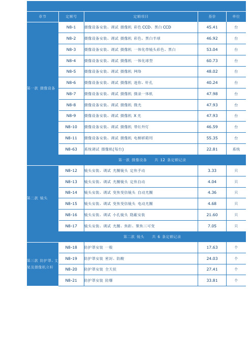
信号解决与放大设备安装、调试鼓励器
24.78
台
N5-32
信号解决与放大设备安装、调试噪声门超级双路
24.78
台
N5-33
信号解决与放大设备安装、调试噪声门四路
49.57
台
N5-34
信号解决与放大设备安装、调试延时器
24.78
台
N5-35
信号解决与放大设备安装、调试反馈克制器
24.78
台
N5-36
112.96
台
N5-61
信号解决与放大设备安装、调试AV、VGA矩阵切换器8×8以内
35.78
台
N5-62
信号解决与放大设备安装、调试AV、VGA矩阵切换器16×16以内
103.73
台
N5-63
信号解决与放大设备安装、调试AV、VGA矩阵切换器32×32以内
168.39
台
N5-64
信号解决与放大设备安装、调试定压变压器
49.02
台
N8-41
视频解决设备安装、调试画面分割器≤8路
25.54
台
N8-42
视频解决设备安装、调试画面分割器≤16路
39.91
台
N8-43
视频解决设备安装、调试网络摄像机专用视频服务器
62.62
台
N8-44
视频解决设备安装、调试云台控制器
28.79
台
N8-45
视频解决设备安装、调试时间、字符发生器
台
N5-46
信号解决与放大设备安装、调试数字音频信号解决器
102.46
台
N5-47
信号解决与放大设备安装、调试分频器
24.78
劳务派遣服务成本控制与优化考核试卷

B.成本核算
C.成本分析
D.成本决策
E.成本控制
2.劳务派遣服务成本优化的方法有:()
A.优化人员结构
B.提高工作效率
C.强化合同管理
D.降低采购成本
E.优化培训体系
3成本对象
B.成本动因
C.成本归属
D.成本分类
E.成本效益
4.劳务派遣服务成本控制的原则包括:()
劳务派遣服务成本控制与优化考核试卷
考生姓名:答题日期:得分:判卷人:
本次考核旨在评估考生对劳务派遣服务成本控制与优化策略的理解和实际应用能力,通过测试考生对成本核算、成本控制方法、成本优化措施等方面的掌握程度,以提升劳务派遣服务领域的专业素质。
一、单项选择题(本题共30小题,每小题0.5分,共15分,在每小题给出的四个选项中,只有一项是符合题目要求的)
2.成本核算的结果可以直接用于成本控制决策。()
3.成本优化的目标就是完全消除成本。()
4.劳务派遣服务成本控制可以完全消除成本超支的风险。()
5.成本控制的重点是事后的成本分析,而非事前的成本预测。()
6.劳务派遣服务成本优化可以通过增加人员编制来实现。()
7.成本核算的准确性不受外部环境因素的影响。()
D.开展成本预测
E.事中成本分析
7.劳务派遣服务成本优化的措施包括:()
A.优化工作流程
B.提高员工技能
C.强化绩效考核
D.优化培训体系
E.增加人员编制
8.劳务派遣服务成本核算的目的是:()
A.反映实际成本
B.为决策提供依据
C.评估成本效益
D.优化成本结构
E.提高成本意识
9.劳务派遣服务成本控制的策略包括:()
九年级部编历史材料解析题答题方法与技巧含答案(2)解析
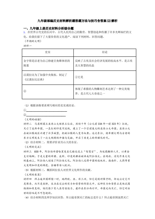
九年级部编历史材料解析题答题方法与技巧含答案(2)解析一、九年级上册历史材料分析综合题1.在世界古代史的长河中,古代人民用自己的勤劳、智慧创造和传播了许多光辉灿烂的文化,给我们留下了大量珍贵的文化遗产。
阅读下列材料,回答问题。
(早期的文明)材料一(1)根据表格要求填写相应的史实或结论。
①______________________________②_____________________________(文明的碰撞)材料二马其顿国王亚历山大继承王位后,历经十年(公元前334年—前323年)征战,灭亡了波斯帝国,一直打到印度河流域,建立了一个空前庞大的亚历山大帝国。
亚历山大在被征服地区兴建了许多城堡,把被征服的人变为奴隶。
这次东征,使希腊文明与古老的东方文明发生了一次大规模的冲撞与交融,开启了历史上的希腊化时代。
(2)结合材料二,简要评价亚历山大的东征。
(文明的交流)材料三 830年,阿拉伯帝国哈里发在巴格达设立“智慧官”,为延揽翻译人才,以黄金支付稿酬。
于是大量的希腊、波斯、印度的典籍被译成阿拉伯文。
在吸收、消化外来文化的基础上,阿拉伯人创造了阿拉伯文化。
阿拉伯人还将中国的造纸术、指南针、火药等重大发明和印度的棉花、食糖等传入欧洲。
(3)根据材料三,概括阿拉伯人对世界文化所作的贡献。
(文明的衰落)材料四拜占庭帝国辉煌一时,地跨欧、亚、非三洲,但它是绝对保守的,命运注定它只是保存,而不是创新,生活在过去的实力和荣誉的阴影之中,这种实力和荣誉正是他试图维持和恢复的,他们很少有人具有创造力,最终在东征西讨中,帝国走向灭亡,但它对后世的影响是不可忽视的。
(4)结合材料四及所学知识回答,拜占庭帝国灭亡的标志是什么?拜占庭帝国虽然灭亡了,但对后来的西欧社会产生了什么影响?(文明的启示)(5)综合上述材料,你觉得应该怎样正确看待古代的文明交流?2.材料一:当立法权和行政权集中在同一个人或同一个机关之手,自由便不复存在了。
南京预算
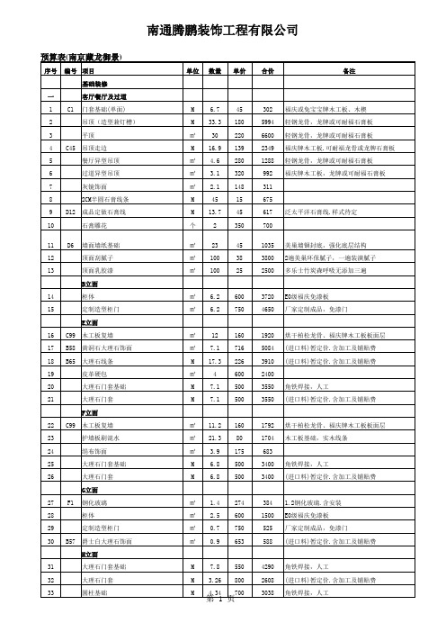
13 14 15 16 17
B14 B55 B56 E43 E44
地暖找平费 黑金砂过门石 过门石安装 安装洁具 安装五金
㎡ M M 件 套
3.4 0.84 0.84 2 1
47 171 21 58 68
160 144 18 116 68
四
客卧
第 3 页
南通腾鹏装饰工程有限公司
预算表(南京藏龙御景)
14 15 16 17 18
B14 B55 B56 E43 E44
地暖找平费 黑金砂过门石 过门石安装 安装洁具 安装五金
㎡ M M 件 套
5 0.83 0.83 2 1
47 171 21 58 68
235 142 17 116 68
七 1 2 3 4 5 6 7 8 9 10 11 12 13 D6 C45 D12 C3
B9 B14 Bቤተ መጻሕፍቲ ባይዱ5 B56
复合地板地面找平(3cm-5cm) 地暖找平费 黑金砂过门石 过门石安装
㎡ ㎡ M M
13.4 13.4 0.88 0.88
40 47 171 21
536 630 150 18
五 1 2 3 4 5 6 7 8 9 10 D6 C45 D12 C3
书房 门套基础 吊顶(造型兼灯槽) 吊顶走边 成品定做石膏线 M M M M M M ㎡ ㎡ ㎡ ㎡ 5.82 11 8.5 8.5 4.44 11 36 15 15 2.9 51 180 139 45 66 15 45 38 25 520 297 1980 1182 383 293 165 1620 570 375 1508
第 1 页
南通腾鹏装饰工程有限公司
预算表(南京藏龙御景)
序号 33 34 35 36 B55 B56 编号 项目 圆柱基础 圆柱贴大理石 黑金砂过门石 过门石安装 I立面 37 38 39 F8 C99 木工板复墙 护墙板刷混水 银镜 G立面 40 41 42 43 44 45 46 47 B57 柜体 定制造型柜门 爵士白大理石饰面 金属马赛克饰面 灰镜饰面 定制整体柜体 烤漆柜门 五金 K立面 48 49 50 隔断造型 吧台制作 不锈钢挂件 W立面 51 52 53 54 55 56 C99 实木线条 C128 软包 皮革硬包 木工板复墙 定做隐形门 闭门器 M ㎡ ㎡ ㎡ 樘 套 12.5 1.2 2.6 2.5 1 1 50 600 600 160 2000 240 625 720 1560 400 2000 240 项 M 项 1 1.5 1 3800 2500 300 3800 3750 300 ㎡ ㎡ ㎡ ㎡ ㎡ ㎡ ㎡ 套 6.6 1.7 1.2 4.4 0.6 8.3 8.3 1 600 400 653 450 148 650 700 2500 3960 680 784 1980 89 5395 5810 2500 ㎡ ㎡ ㎡ 16.8 32.6 2.8 160 80 100 2688 2608 280 单位 M M M M 数量 4.34 4.34 3.36 3.36 单价 700 2150 171 21 合价 3038 9331 575 71
2023年组装电脑办公最佳配置是多少(台式电脑组装配置推荐)
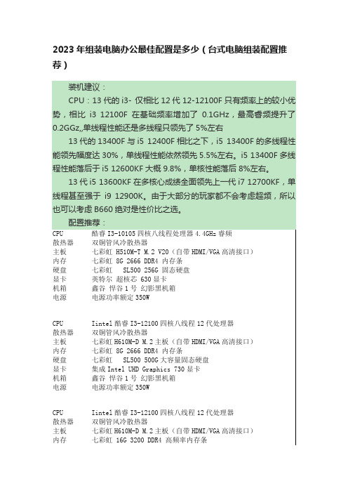
2023年组装电脑办公最佳配置是多少(台式电脑组装配置推荐)
硬盘七彩虹战戟CN600 256G M.2 NVME高速固态硬盘
显卡集成Intel UHD Graphics 730显卡
机箱鑫谷悍谷1号幻影黑机箱
电源电源功率额定350W
CPU Iintel酷睿I3-12100四核八线程12代处理器
散热器双铜管风冷散热器
主板七彩虹H610M-D M.2主板(自带HDMI/VGA高清接口)内存七彩虹 8G 2666 DDR4 内存条
硬盘七彩虹 SL500 500G大容量固态硬盘
显卡集成Intel UHD Graphics 730显卡
机箱鑫谷悍谷1号幻影黑机箱
电源电源功率额定350W
CPU Iintel酷睿I3-12100F四核八线程12代处理器
散热器双铜管风冷散热器
主板七彩虹H610M-D M.2主板(自带HDMI/VGA高清接口)内存七彩虹 8G 2666 DDR4 内存条
硬盘七彩虹 SL500 500G大容量固态硬盘
显卡七彩虹 GeForce GT 1010 2G 独显畅玩原神LOL网游机箱鑫谷悍谷1号幻影黑机箱
电源电源功率额定350W。
- 1、下载文档前请自行甄别文档内容的完整性,平台不提供额外的编辑、内容补充、找答案等附加服务。
- 2、"仅部分预览"的文档,不可在线预览部分如存在完整性等问题,可反馈申请退款(可完整预览的文档不适用该条件!)。
- 3、如文档侵犯您的权益,请联系客服反馈,我们会尽快为您处理(人工客服工作时间:9:00-18:30)。
②暂估价合价数据关联
③人工费合价数据关联
④机械费合价数据关联
13.3.2 消防工程(消火栓)招标控制价的编制
编制综合单价分析表2/3 根据项目特征描述的内容逐一编制
13.3.2 消防工程(消火栓)招标控制价的编制
编制综合单价分析表2/3
答案
13.3.2 消防工程(消火栓)招标控制价的编制
②人工费、机械费的数据关联
④完善脚手架搭拆相关数据的关联
13.3.2 消防工程(消火栓)招标控制价的编制
9、编制单价措施项目清单与计价表
⑤计算“单价措施项目”合计
13.3.2 消防工程(消火栓)招标控制价的编制
10、编制总价措施项目清单与计价表
13.3.2 消防工程(消火栓)招标控制价的编制
10、编制总价措施项目清单与计价表
材料费单价 机械费单价 管理费和利润单价 (人工费+机械费)*(17.72%+ 15.04%)
13.3.2 消防工程(消火栓)招标控制价的编制
4、编制综合单价分析表 根据项目特征描述的内容逐一编制
④计算管道安装工程未计价材料及其相关费用
13.3.2 消防工程(消火栓)招标控制价的编制
4、编制综合单价分析表 根据项目特征描述的内容逐一编制
13.3.2 消防工程(消火栓)招标控制价的编制
编制消防工程招标控制价的实施步骤
1. 熟悉施工图纸、计价规范、定额及相关资料
2. 熟悉工程量清单内容,核算工程量 3. 确定分部分项工程费
4. 确定措施项目费
5. 其他项目清单计价 6. 规费、税金项目清单计价 7. 报价款组成
13.3.2 消防工程(消火栓)招标控制价的编制
13.3.2 消防工程(消火栓)招标控制价的编制
② 在“暗室计算”文件中,将工程量改为“暗室部分工程量”其他工程量设为“0”
13.3.2 消防工程(消火栓)招标控制价的编制
③ 将“暗室计算”文件综合单价分析表中,凡有“超高增加费”的工程量设为“0”
13.3.2 消防工程(消火栓)招标控制价的编制
建筑设备 安装工程预算
建筑工程学院
2018.3.
工作任务 13
消防工程的工程量清 单编制与清单计价
知识 目标 能力 目标
(1)掌握消防工程工程量清单的编制方法 (2)掌握消防工程招标控制价的编制方法 能够达到正确编制消防工程工程量清单 和招标控制价的目的
素质 目标
(1)培养学生团队协作精神; (2)培养学生严谨细致的工作态度; (3)培养学生良好的职业操守和吃苦耐劳的工作作风
费率按费用定额规定填写
13.3.2 消防工程(消火栓)招标控制价的编制
11、编制总承包服务费计价表
13.3.2 消防工程(消火栓)招标控制价的编制
11、编制总承包服务费计价表
13.3.2 消防工程(消火栓)招标控制价的编制
12、编制其他项目清单与计价汇总表
13.3.2 消防工程(消火栓)招标控制价的编制
8、编制单价措施项目综合单价分析表
⑤ 将求得的“暗室部分人工费”(6689.87元)代入综合单价分析表中,分析计算
13.3.2 消防工程(消火栓)招标控制价的编制
8、编制单价措施项目综合单价分析表
13.3.2 消防工程(消火栓)招标控制价的编制
9、编制单价措施项目清单与计价表
①综合单价数据关联 ③计算合价
13.3.2 消防工程(消火栓)招标控制价的编制
16、与定额计价模式计算结果的比较
(1)消防工程招标控制价相关知识
本节 重点
(2)消防招标控制价的编制方法
(3)消防招标控制价的编制步骤
编制综合单价分析表2/3
答案
13.3.2 消防工程(消火栓)招标控制价的编制
编制综合单价分析表2/3
答案
13.3.2 消防工程(消火栓)招标控制价的编制
6、编制综合单价分析表 (暂估价的处理)
13.3.2 消防工程(消火栓)招标控制价的编制
6、编制综合单价分析表 (暂估价的处理)
扣除焊接法兰的材料费
⑦计算人工费、材料费、机械费、管理费和利润的小计值
13.3.2 消防工程(消火栓)招标控制价的编制
4、编制综合单价分析表 根据项目特征描述的内容逐一编制
⑧计算未计价材料费
13.3.2 消防工程(消火栓)招标控制价的编制
4、编制综合单价分析表 根据项目特征描述的内容逐一编制
⑨计算清单项目综合单价
5、填写、完善分部分项工程量清单与计价表,ቤተ መጻሕፍቲ ባይዱ联数据
这些数据均抄自工程量清单表(应核对工程量)
这些数据暂空,不填写
13.3.2 消防工程(消火栓)招标控制价的编制
4、编制综合单价分析表 根据项目特征描述的内容逐一编制
①抄(分部分项工程量清单与计价表)数据
②确定定额项目名称,查定额,确定定额编号、定额单位,计算单价 ③计算人工费、材料费、机械费、管理费和利润的合价
13、编制规费、税金项目清单与计价表
13.3.2 消防工程(消火栓)招标控制价的编制
13、编制规费、税金项目清单与计价表
费率按费用定额规定填写
13.3.2 消防工程(消火栓)招标控制价的编制
14、编制单位工程招标控制价汇总表
13.3.2 消防工程(消火栓)招标控制价的编制
15、完善扉页招标控制价 将各表格按规范顺序排列整齐
编制综合单价分析表10/11
答案
13.3.2 消防工程(消火栓)招标控制价的编制
编制综合单价分析表10/11
答案
13.3.2 消防工程(消火栓)招标控制价的编制
7、逐项完成分部分项工程量清单与计价表的数据关联及计算
以主项所在定额分册归类汇总
13.3.2 消防工程(消火栓)招标控制价的编制
8、编制单价措施项目综合单价分析表
增加沟槽式法兰材料费
换算法兰材料
13.3.2 消防工程(消火栓)招标控制价的编制
6、编制综合单价分析表 (暂估价的处理)
关联相关数据
13.3.2 消防工程(消火栓)招标控制价的编制
编制综合单价分析表10/11
13.3.2 消防工程(消火栓)招标控制价的编制
编制综合单价分析表10/11
答案
13.3.2 消防工程(消火栓)招标控制价的编制
为计算“非夜间施工增加费”必须先求“暗室部分的人工费”其方法与定额计价相似 ① 将“招标控制价”的整个文件,另存为“暗室计算”文件
② 在“暗室计算”文件中,将工程量改为“暗室部分工程量”其他工程量设为“0”
③ 将“暗室计算”文件综合单价分析表中,凡有“超高增加费”的工程量设为“0” ④ 在“暗室计算”文件的“分部分项工程量清单与计价表”中,提取“暗室部分的 人工费”——即为所求。
③ 将“暗室计算”文件综合单价分析表中,凡有“超高增加费”的工程量设为“0”
逐一修改各“综合单价分析表”
13.3.2 消防工程(消火栓)招标控制价的编制
④ 在“暗室计算”文件的“分部分项工程量清单与计价表”中,提取“暗室部分的 人工费”——即为所求。
13.3.2 消防工程(消火栓)招标控制价的编制
⑤计算管道冲洗费用,工程量与管道安装相同
13.3.2 消防工程(消火栓)招标控制价的编制
4、编制综合单价分析表 根据项目特征描述的内容逐一编制
⑥计算管道安装和冲洗相关部分的超高增加费 注意:此处的工程量是超高部分的管道工程量
13.3.2 消防工程(消火栓)招标控制价的编制
4、编制综合单价分析表 根据项目特征描述的内容逐一编制
1、已知条件 —— 招标工程量清单
13.3.2 消防工程(消火栓)招标控制价的编制
1、已知条件 —— 招标工程量清单
2、编制招标控制价用表 按照10.3所述内容,编制整套“招标控制价”用表,供计价使用。
13.3.2 消防工程(消火栓)招标控制价的编制
3、编制分部分项工程量清单与计价表
增加2列,便于计价
