ABB电动门说明书
ABB 门磁 灯光开关机械器操作指南说明书
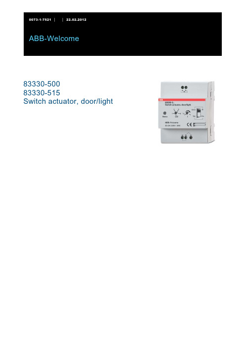
ABB-Welcome83330-50083330-515Switch actuator, door/light1Safety (3)2Intended use (3)3Environment (3)3.1ABB devices (3)4User Manual (3)5Operation (4)5.1Standard operation (4)6Technical data (5)7Mounting / Installation (6)7.1Requirements for the electrician (6)7.2General installation instructions (6)7.3Mounting (7)7.4Connection (7)1 SafetyWarningE lec tric voltage!Risk of death and fire due to electrical voltage of 230 V.– Work on the 230V supply system may only be performed by authorised electricians!– Disconnect the mains power supply prior to installation and/or disassembly!2 Intended useThe 83330-500 switch actuator is an integral part of the ABB-Welcome door communication system and operates exclusively with components from this system. The device must only be installed on mounting rails according to DIN EN 500022.EnvironmentC ons ider the protec tion of the environment!Used electric and electronic devices must not be disposed of with domestic waste.– The device contains valuable raw materials which can be recycled. Therefore, dispose of the device at the appropriate collecting depot.3.1A B B devic esAll packaging materials and devices from ABB bear the markings and test seals for proper disposal. Always dispose of the packaging material and electric devices and their components via the authorized collecting depots and disposal companies.ABB products meet the legal requirements, in particular the laws governing electronic and electrical devices and the REACH ordinance.(EU-Directive 2002/96/EG WEEE and 2002/95/EG RoHS)(EU-REACH ordinance and law for the implementation of the ordinance (EG) No.1907/2006)4 User ManualDetailed information for planning ABB-Welcome systems is contained in the user manual. Download at.ABB-Welcome Operation5 Operation5.1S tan dard operationFig. 1:ABB-Welcome Technical data 6 Technical dataDes ignation V alueOperating temperature (EN 50486) -5° C – +45° CStorage temperature -20°C – +70°CProtection IP 20Single-wire clamps 2 x 0.6 mm² – 2 x 1 mm²Fine-wire clamps 2 x 0.6 mm² – 2 x 0.75 mm²Volume Maximum 80 dBBus voltage 28 V- ±2 VDoor opener Maximum 3 ASize 4 TESwitch actuator, light:•Neon light 350 W•230 V Halogen lamp 300 W•Low-voltage halogen light with conventional350 VAtransformer•Low-voltage halogen light with electrical transformer 300 VA7 Mounting / InstallationWarningE lec tric voltage!Risk of death and fire due to electrical voltage of 230 V.– Low-voltage and 230 V cables must not be installed together in a flush-mounted socket!In case of a short-circuit there is the danger of a 230 V load on the low-voltage line.7.1R equirements for the elec tric ianWarningE lec tric voltage!Install the device only if you have the necessary electrical engineering knowledge and experience.•Incorrect installation endangers your life and that of the user of the electrical system.•Incorrect installation can cause serious damage to property, e.g. due to fire.The minimum necessary expert knowledge and requirements for the installation are as follows:•Apply the "five safety rules" (DIN VDE 0105, EN 50110):1. Disconnect from power;2. Secure against being re-connected;3. Ensure there is no voltage;4. Connect to earth;5. Cover or barricade adjacent live parts.•Use suitable personal protective clothing.•Use only suitable tools and measuring devices.•Check the type supply network (TN system, IT system, TT system) to secure the following power supply conditions (classic connection to ground, protective earthing, necessaryadditional measures, etc.).7.2G eneral ins tallation ins truc tions•Terminate all branches of the wiring system via a connected bus device (e.g., indoor station, outdoor station, system device).•Do not install the system controller directly next to the bell transformer and other power supplies (to avoid interference).•Do not install the wires of the system bus together with 230 V wires.•Do not use common cables for the connecting wires of the door openers and wires of the system bus. •Avoid bridges between different cable types.•Use only two wires for the system bus in a four-core or multi-core cable.•When looping, never install the incoming and outgoing bus inside the same cable.•Never install the internal and external bus inside the same cable.7.3MountingThe device 83330-500 must only be installed on mounting rails according to DIN EN 500022.7.4C onnec tionFig. 2:No. F unc tion1 •Connection for the system controller•When using several indoor stations: connection for the internal bus2 Depending on the operating mode selected.•Connection for a door opener•Connection for lightingABB-Welcome0073-1-7521 | | 22.02.2012A member of the ABB GroupBusch-Jaeger Elektro GmbH PO box58505 LüdenscheidFreisenbergstraße 2 58513 Lüdenscheid Germany ***************.comCentral sales service:Phone: +49 180 5 669900 Fax: +49 180 5 669909NoticeWe reserve the right to at all times make technical changes as well as changes to the contents of this document without prior notice. The detailed specifications agreed to at the time of ordering apply to all orders. ABB accepts no responsibility for possible errors or incompleteness in this document.We reserve all rights to this document and the topics and illustrations contained therein. The document and its contents, or extracts thereof, must not be reproduced, transmitted or reused by third parties without prior written consent by ABB.Copyright© 2012 Busch-Jaeger Elektro GmbH All rights reserved。
abb说明书
1、参数Par1.04是MOTOR SPEED(电机转速)。
2、需要查看逆变器软件版本应查询(Par 4.01)。
3、查看ABB ACS800的主控制字应该查询(Par7.01)。
4、 ACS800系统程序中数字量输入位于第(10)参数组。
5、在ACS800系统程序中,关于电机启停方式的设定是在第21参数组,通过(Par21.01)选择电机的启停方法,如果需要比较高的启动转矩应选择(DC MAGN)启动方式。
6、在ACS800系统程序中,如何定义加减速时间?在第22参数组中,通过设定Par22.01(加速时间)、Par22.02(减速时间)和Par22.03(加减速乘法器)来定义加减速时间。
7、在ACS800系统程序中如何将加减速斜坡的形状由线型斜坡改为S型斜坡?将参数Par22.05(SHAPE TIME)由0.00s改为0.01s…1000.00s之间的任何一个数据即可将加减速斜坡的形状由线型斜坡改为S型斜坡。
8、在ACS800系统软件中如何激活速度控制器的自动调节功能?将参数Par24.01(PI TUME)设置为1即可激活激活速度控制器的自动调节功能。
9、在ACS800系统软件中激活速度控制器自动调节后更新哪些参数?由于该调节给予机械时间常数的估计值,激活速度控制器自动调节后将更新Par24.03 KPS(速度控制器的相对增益),Par24.09 TIS(速度控制器的积分时间)和Par24.15 ACC COMP DER TIME(加速度补偿的滤波时间)。
10、在ACS800系统软件中,如果已经激活电机电缆热保护功能,在何种情况下会出现CABLE TEMP报警和故障信号?如果电缆温升超过102%,系统会给出一个CABLE TEMP报警信号;如果温升超过106%,传动将给出CABLE TEMP故障信号。
11、在ACS800系统软件中,第51参数组的名称和功能分别是什么?第51参数组是MASTER ADAPTER,即现场总线适配器设置,该组参数定义了现场适配器模块的通信参数。
ABB_电动机产品使用说明书
其它语种译本可向 ABB 索取。 ZH ă 2
ABB/低压电机/使用手册 ZH-EN 12-2004
ZH
低压电机
安装、操作及维护手册
目录
页
1. 一般说明 ......................................................................................................................................................... 4 1.1 符合性声明.......................................................................................................................................... 4 1.2 有效范围 .............................................................................................................................................. 4
此外,作为零部件,这些产品符合以下基本要求:
电磁兼容 (EMC) 指令 89/336/EEC(由 92/31/EEC 和 93/68/EEC 修订),该指令涉及辐射和 抗干扰水平的内在特性,
且符合:
EN 60 034-1
要求:
机器指令 98/37/EEC,该指令规定机器应由机器制造商正确安装(例如:符合本公司的安装说明和 EN 60 204“工业机器电气设备”)
低压电机
ABB电动门调试方法
ABB电动门调试方法1.把切换开关打到(local)就地。
2.长按(stop)键进入菜单组P1,按至P2。
长按(stop)至P2.1(oper-key)选择本地控制面板上按扭的工作模式,长按(stop)进入,按或选择(inchmode)点动,短按(stop)显示(save)保存,再短按(stop),(save)由闪烁至出现该级菜单,数据已保存。
3、按选择P2.2,显示(dig-inp)选择数字输入口的工作模式,长按(stop)进入,按或选择(inchmode)点动,短按(stop)显示(save)保存,再短按(stop),(save)由闪烁至出现该级菜单,数据已保存。
4、短按(stop)至P1菜单组,长按(stop)至P1.1,显示(torque-o)开向力矩,长按(stop)显示40%,按设置为50%,短按(stop),保存数据。
5、按至P1.2显示(torque-c)关向力矩,长按(stop)进入,显示40%,按设置为50%,短按(stop),保存数据。
6、按至P1.5,显示(cutoff-o)开向行程或力矩决定停机,长按(stop)进入,按选择(travel)行程短按(stop)显示(save),再短按(stop),(save)由闪烁至出现该级菜单,数据已保存.7、按至P1.7,显示(cutoff-o)关向行程或力矩决定停机,长按(stop)进入,按选择(travel)行程,短按(stop)显示(save),再短按(stop),(save)由闪烁至出现该级菜单,数据已保存.8、按至P1.9,显示(adjust-o)开向终端位置,长按(stop)进入,按()按钮直至开到位,短按(stop)显示(save),再短按(stop),(save)由闪烁至出现该级菜单,保存结束。
9、按至P1.10,显示(adjust-c)开向终端位置,长按(stop)进入,按()按钮直至开到位,短按(stop)显示(save),再短按(stop),(save)由闪烁至出现该级菜单,保存结束。
ABB电机说明书readdata.jsp

三相异步电动机使用维护说明书上海ABB电机有限公司2007年6月ABB电机使用维护说明书一、产品介绍1、适用范围本说明书适用于ABB各标准系列及其所派生的各种系列电机(防爆系列电机除外)。
机座中心高:56-355。
(对一些特殊应用场合或有特殊设计考虑的型号电机还需参阅其它特别的指导说明)。
二、一般要求1、起动1.1 收货检验∙收货后,立即检验电机有无外部损伤,检验所有的铭牌数据,尤其是电压和绕组的连接方式(Y 或△)。
∙用手旋转转轴,检测电机空转情况,如果电机装有锁定装置,注意将其打开。
1.2 绝缘性能检测∙电机初次使用之前,绕组有可能受潮,都要测量其绝缘阻值。
∙25℃时测量的绝缘电阻值应超过参考值,20×URi ≥ MΩ1000+2PU=电压 V, P=输出功率 kW[注意]测量后绕组要立即放电,避免电击。
∙周围环境温度每升高20℃,电阻的参考值减少一半。
∙如果没有达到绝缘电阻的参考值,绕组就必须烘干。
∙烘炉的温度为90℃,时间12-16小时。
∙如果安装了排水塞,烘干时必须将其打开。
∙绕组被海水浸泡后一般要重绕。
1.3 直接起动或 Y/△起动∙标准单速电机的接线盒一般有6个接线螺栓和至少1个接地螺栓。
∙电机通电之前,必须按规定要求可靠接地,不能接零代替接地。
∙电压和绕组连接方式在铭牌上有标注。
1.3.1 直接起动绕组可以采用 Y或△接法,例如660VY,380V△分别表示660V,Y接法和380V,△接法。
1.3.2 Y/△起动∙电源电压必须等于△接法电机的额定电压。
∙拆下接线板上所有的接线片,按Y/△起动装置接线,妥善连接到电机六个接线柱上,并能从起动初期的Y连接跳到启动完成的△接。
∙双速电机和其他特种电机的电源接法必须依照接线盒内的接线图说明。
1.4 接线柱和旋转方向∙如果电源相序U1,V1,W1依次与接线柱U1,V1,W1连接,从电机的驱动端观察转轴,其旋转方向为顺时针。
∙换接电源线中的任意两相就可以改变电机的旋转方向。
ABB阀门定位器中文说明书

TZID-C 智能定位器 安装及操作说明书 MOTOYAMA ENG. WORKS LTD本山製作所株式 会社气路连接•使用与定位器气源端口处标识的标准接口连接气源•连接定位器的输出与气动执行器的气缸电气连接根据下列接线端子图以及设计要求进行相应的配线(一般只需+11,-12,+31,-32)调试步骤1.接通气源,检查减压阀后压力是否符合执行器的铭牌参数要求(定位器的最大供气压力为7BAR,但实际供气压力必须参考执行器所容许的最大气源压力)。
2.接通4---20mA输入信号。
(定位器的工作电源取自输入信号,由DCS二线制供电,不能将DC24V直接加至定位器,否则有可能损坏定位器电路)。
3.检查位置返馈杆的安装角度(如定位器与执行器整体供货,则已经由执行器供货商安装调试完毕,只需作检查确认,该步并非必须):•按住MODE键。
•并同时点击⇧或⇩键,直到操作模式代码1.3显示出来。
•松开 MODE键。
•使用⇧或⇩键操作,使执行器分别运行到两个终端位置,记录两终端角度•两个角度应符合下列推荐角度范围(最小角位移20度,无需严格对称)直行程应用范围在 -28º--- +28º之内。
角行程应用范围在 -57º--- +57º之内。
全行程角度应不小于25º4.切换至参数配置菜单•同时按住⇧和⇩键•点击ENTER键•等待3秒钟,计数器从3计数到0•松开⇧和⇩键程序自动进入P1.0配置菜单。
5.使用⇧和⇩键选择定位器安装形式为直行程或角行程。
角行程安装形式:定位器没有返馈杆,其返馈轴与执行器角位移输出轴同轴心一般角位移为90º直行程安装形式:定位器必须通过返馈杆驱动定位器的转动轴,一般定位器的返馈杆角位移小于60º, 用于驱动直行程阀门气动执行器。
注意:进行自动调整之前,请确认实际安装形式是否与定位器菜单所选形式相符,因为自动调整过程中定位器对执行器行程终端的定义方法不同,且线性化校正数据库不同,可能导致较大的非线性误差。
【VIP专享】ABB使用说明书最新版

前言衷心感谢您使用“华振”牌智能变频供水设备,我们将为您提供优质的产品和星级的售后服务。
我公司吸取行业内智能变频供水设备的技术精髓,集长期从事水泵行业和智能变频供水设备的设计经验,研制开发的ZBH第三代、第四代、第五代、第六代智能变频供水设备,已广泛运于高层建筑、住宅楼、商住楼、新老小区降耗节能改造、高级宾馆、医院、学校、工矿企业的生产生活用水等,是一种节能型,现代化,智能化的变频供水设备。
本使用说明书向您详细介绍了“华振”牌系列智能变频供水设备的产品说明、技术说明、操作、故障处理,保养维护等各方面内容。
为了更好的使用智能变频供水设备,请您在操作前仔细阅读本说明书,这将会:●帮助您了解智能变频供水设备的结构及性能特点。
●避免由于操作不当而引起的设备故障。
●提高设备的使用寿命。
●增强设备使用的可靠性。
值得注意的是,本说明书的资料及图形在出版时是正确的,但我公司产品的结构和性能总在不断地改进和完善,本说明书的相关内容可能有变化,恕不一一通知,敬请谅解。
感谢您对“华振”的信任,衷心地祝愿您在事业中大展宏图,取得辉煌成就。
成都华振供水设备有限公司- 1 -))1 MΩ电阻与机壳连接用于模拟输入电位器的给定电压输出.10 V±2%))1 MΩ电阻与机壳连接频率。
0…20 mA ( 数字输入6,可编程。
默认Ω。
数字输入最大电压一般显示性能软键功能每个软键上方的文字描述的是当前软键功能的含义。
显示对比度同时按住 MENU (菜单)键和 UP (向上)或DOWN (向下)可以改变显示对比- 5 -顶行液晶屏的顶行显示变频器的基本的状态信息。
• LOC (本地) - 表示变频器处于本地控制,即控制命令来自控制盘。
• REM (远程) - 表示变频器处于远程控制, 例如 I/O (X1) 或现场总线。
• - 显示变频器和电机的旋转状态:4、应用宏的选择 中崛供水设备应用宏选择,用于泵的循环软起控制中,在ABB 变频器设置中9902的值为15(SPFC 控制).注意! 参数2108 START INHIBIT (禁止起动)必须保持为默认设置0 (OFF)。
ABB说明书
基本操作及编程培训IRC5 机器人系统IRC5 Basic Operation and Programming Training上海ABB工程有限公司 ABB Engineering (Shanghai) Ltd. 教材编号:S5-100 2006年03月IRC5 Basic Operation And Programming Training 基本操作及编程培训 2IRC5 Basic Operation And Programming Training 基本操作及编程培训Content 目录1 Overview 介绍 ...................................................................................................................................5 2 Safety and environment protection 系统安全及环境保护 ............................................................6 3 General 系统概述..............................................................................................................................73.1 IRC5 System IRC5系统............................................................................................................................. 7 3.2 Consist of the system 系统组成................................................................................................................. 8 4 Start the controller 启动.................................................................................................................10 4.1 Buttons on the Control module 控制单元柜按键.................................................................................. 10 4.2 Buttons on the Drive module 驱动单元柜按钮...................................................................................... 12 4.3 Start the controller 启动........................................................................................................................... 13 5 Shut down the controller 关机 .......................................................................................................14 6 FlexPendant 示教器 ........................................................................................................................15 6.1 Buttons on the FlexPendant 示教器按键................................................................................................. 16 6.2 The ABB Menu ABB菜单..................................................................................................................... 18 6.3 Close Button 关闭键.............................................................................................................................. 19 6.4 Task Bar 任务栏 .................................................................................................................................... 19 6.5 Status Bar 状态栏 .................................................................................................................................... 20 6.6 The Quickset menu 快捷菜单.................................................................................................................. 20 6.7 Soft keyboard 软键盘 ............................................................................................................................. 21 6.8 Scrolling and Zooming 磙动与缩放...................................................................................................... 21 7 Jogging the robot using the Joystick 使用操纵摇杆移动机器人 ................................................23 8 Precise positioning 精确定点..........................................................................................................29 8.1 Incremental movement 步进运动 ............................................................................................................ 29 9 Load a program 加载程序.............................................................................................................31 9.1 Load an existing program 加载一个已存在的程序 ................................................................................ 31 9.2 Start and test a program in Manual mode手动测试程序......................................................................... 33 10 Stopping the program 停止程序 ....................................................................................................38 11 Running a program in Automatic mode自动运行程序 ...............................................................39 12 Rapid Programming Rapid编程....................................................................................................41 12.1 Consist of the program 程序的组成 ........................................................................................................ 41 12.2 Basic Movement Instructions 基本运动指令 .......................................................................................... 42 12.3 Input/Output Instructions 输入/输出指令 ............................................................................................... 45 12.4 Communication Instructions 通讯指令 ................................................................................................... 46 12.5 Program Fflow Control Instructions 程序流程指令................................................................................ 46 12.6 Other Common Instructions 其他常用指令 ............................................................................................ 47 13 Editing a program 编辑程序 ..........................................................................................................48 13.1 Modify positions (tune with motions) 修改位置点 ................................................................................. 48 13.2 Editing instruction arguments 编辑指令变量.......................................................................................... 49 13.3 Adding instructions 增加指令 ................................................................................................................. 52 13.4 Programming a delay 编辑延迟 .............................................................................................................. 543IRC5 Basic Operation And Programming Training 基本操作及编程培训14 I/O Signals 输入/输出信号..............................................................................................................57 14.1 Programming an I/O instruction 编辑一条输入/输出指令..................................................................... 5715 Event log 事件纪录..........................................................................................................................60 15.1 What is a log? 什么是纪录?.................................................................................................................. 60 15.2 What is an event? 什么是事件? ............................................................................................................ 60 15.3 What is an event message? 什么是事件信息? ...................................................................................... 60 15.4 What is an information message? 什么是通知信息?............................................................................ 61 15.5 What is a warning? 什么是警告? .......................................................................................................... 61 15.6 What is an error? 什么是错误? ............................................................................................................. 61 15.7 What is "acknowledge"? 什么是确认 ?................................................................................................. 61 15.8 Open and close the event log 打开关闭事件纪录................................................................................... 61 15.9 View a message 查看信息....................................................................................................................... 6216 Emergency stop 紧急停止 ..............................................................................................................64 17 Operational modes 运行模式 .........................................................................................................6517.1 What is the manual mode? 什么是手动模式? ...................................................................................... 65 17.2 Manual mode 100% (Option, testing mode)手动全速(选项,测试模式)......................................... 65 17.3 Automatic mode (production mode) 自动模式(生产模式)................................................................ 66 18 Maintenance 机器人保养检查表 ...................................................................................................69 18.1 Manipulator 机器人本体 ......................................................................................................................... 69 18.2 Controller 机器人控制柜 ........................................................................................................................ 69 18.3 Other 其它................................................................................................................................................ 69 在没有声明的情况下,文件中的信息会发生变化。
abb说明书

ESD功能
输入端口 BE1 BE2 BE3 BE4
状态输出端口
BA1
BA2
基型
BA3
BA4
BA5
385
BA6
387
BA7
BA8
ONTRAC带有最多8个开 关量输出端口(光电隔 离),每个输出端口均 可被定义为如右图所示 的不同功能,并可选择 触点的“常开”或“常 闭”状态。
基型产品: 带有开关量控制功能和4个开关量输出端口 385功能板:增加4个开关量输出端口和1个模拟量阀位输出端口 386功能板:Profibus-DP总线通讯板 387功能板:增加模拟量阀位输入输出端口和3个开关量输出端口
SCY09-01A
04
MME / MOE 智能电动执行机构
电气接线
通入电缆相关数据见下表
接线方式 直接接线(默认) 分体式接线 接插式接线
总线接插式接线
电缆护线接头螺纹规格(适应电缆直径) 2个 M32×1.5(φ13~φ18mm) 2个 M32×1.5(φ13~φ18mm) 2个 M32×1.5(φ13~φ18mm) 1个 M32×1.5(φ13~φ18mm) 2个 M16×1.5(φ4.5~φ8mm)
● 设定转速: 20%~100%可调,步距5%
● 基本误差: 1)多转式电动执行机构(行程≥2圈) 2)角行程电动执行机构 3)直行程电动执行机构(行程≥25mm)
≤±1% ≤±1% ≤±1%
● 控制死区: 1%(0.5~10%可调)
● 中途限位: 1)开限位设置范围为 2)关限位设置范围为
有特殊要求的改造项目 ● 电气部分充分的抗干扰和防冲击设计,使产品运行极为稳定,并有效杜绝了“电网污染”问题 ● 超高的定位精度,即使在全行程(多回转)2圈的情况下,也能够达到1%的定位精度 ● 广泛的监视与自诊断功能,帮助用户迅速准确地判断执行机构甚至阀门的运行状态 ● 完善的安全防护功能,可有效杜绝现场误操作或在系统紧急故障时将危害降低至最小 ● 简洁高效的人机交互界面和非侵入式设计,使现场安装调试变得异常简单 ● 可靠的电路设计和简单的机械结构造就了超长的使用寿命
ABB--AV气动门说明

ABB-AV气动门说明书一、AV1120200的调试Forward:向前的,reverse:反面的,倒转Calibrate:校正,operate:操作,运转AV1120200气动定位器自带有4~20mA位置反馈板,反馈电位器为2000Ω单圈电位器。
电位器无止档。
移除反馈板FOR/REV跳线,将CAL/OPER跳线置CAL位置,面对定位器盖子,输出臂逆时针旋转,反馈板电位器测试端TP1\TP2电阻值应由0~2000Ω变化,拧满一圈开路后归零。
反馈板原理如图一所示。
图一、Calibration Features for4 to 20-mA Position Transmitter 定位器出厂时安装黑色反馈凸轮(direct acting cam,90°,控制信号I与位置反馈信号P关系A为根号、B为线性、C为平方),为正向作用,即控制信号I增加,面对定位器盖子,输出臂逆时针旋转(同国产DKJ执行器,出厂时面对执行机构输出臂,输出轴顺时针旋转为开大),对应反馈板跳线应设为FOR。
如图二左侧示意。
定位器盖子上还配有红色反馈凸轮(reverse acting cam),为反向作用,即控制信号I增加,面对定位器盖子,输出臂顺时针旋转,对应反馈板跳线应设为REV。
如图二右侧示意。
1图二、定位器正向反向工作示意定位器共有4个工作气口,其中S接气源,I接I/P来控制气信号,01\02接执行器气缸。
当控制信号增加时,01口气压将从0到全压逐步增加,反之,02口气压将从全压到0逐步减小。
挡板的开关控制包括三个环节,依次为DCS模拟操作器、就地控制柜I/P (SMC ITV2010-012S,4~20mA输入开度指令对应)、就地AV1120200气动定位器。
如果挡板开关方向与DCS指令电流变化方向相反,从原则来讲是不规范的,应择机同一规范调试。
下面是二次风挡板执行器规范调试的几个原则,如无异议请遵照执行。
就地控制柜SMC ITV2010-012S电气转换器,接收DCS来4~20mA阀位指令,对应输出控制气压为0.005~0.1MPa,该信号气压经继动器放大(仅λ DCS模拟操作器输出0%~100%对应4~20mA 全关至全开指令,反馈0%~100%对应4~20mA反馈输入,相应也为全关至全开。
ABB 电动机说明书
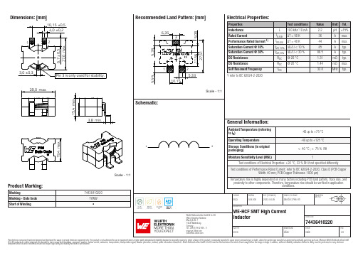
Dimensions: [mm]Scale - 1:17443641022074436410220744364102207443641022074436410220T e m p e r a t u r eT pT L74436410220Cautions and Warnings:The following conditions apply to all goods within the product series of WE-HCF of Würth Elektronik eiSos GmbH & Co. KG:General:•This electronic component was designed and manufactured for use in general electronic equipment.•Würth Elektronik must be asked for written approval (following the PPAP procedure) before incorporating the components into any equipment in fields such as military, aerospace, aviation, nuclear control, submarine, transportation (automotive control, train control, ship control), transportation signal, disaster prevention, medical, public information network, etc. where higher safety and reliability are especially required and/or if there is the possibility of direct damage or human injury.•Electronic components that will be used in safety-critical or high-reliability applications, should be pre-evaluated by the customer. •The component was designed and manufactured to be used within the datasheet specified values. If the usage and operation conditions specified in the datasheet are not met, the wire insulation may be damaged or dissolved.•Do not drop or impact the components, as the core may flake apart.•Würth Elektronik products are qualified according to international standards, which are listed in each product reliability report. Würth Elektronik does not guarantee any customer qualified product characteristics beyond Würth Elektroniks’ specifications, for its validity and sustainability over time.•The customer is responsible for the functionality of their own products. All technical specifications for standard products also apply to customer specific products.Product specific:Soldering:•The solder profile must comply with the Würth Elektronik technical soldering specification. All other profiles will void the warranty. •All other soldering methods are at the customers’ own risk.Cleaning and Washing:•Washing agents used during the production to clean the customer application may damage or change the characteristics of the wire insulation, marking or plating. Washing agents may have a negative effect on the long-term functionality of the product. Potting:•If the product is potted in the costumer application, the potting material may shrink or expand during and after hardening. Shrinking could lead to an incomplete seal, allowing contaminants into the core. Expansion could damage the core or wire contacts. Werecommend a manual inspection after potting to avoid these effects. Storage Conditions:• A storage of Würth Elektronik products for longer than 12 months is not recommended. Within other effects, the terminals may suffer degradation, resulting in bad solderability. Therefore, all products shall be used within the period of 12 months based on the day of shipment.•Do not expose the components to direct sunlight.•The storage conditions in the original packaging are defined according to DIN EN 61760-2.Packaging:•The packaging specifications apply only to purchase orders comprising whole packaging units. If the ordered quantity exceeds or is lower than the specified packaging unit, packaging in accordance with the packaging specifications cannot be ensured. Handling:•Violation of the technical product specifications such as exceeding the nominal rated current will void the warranty•Applying currents with audio-frequency signals may result in audible noise due to the magnetostrictive material properties. •Due to heavy weight of the components, strong forces and high accelerations may have the effect to damage the electrical connection or to harm the circuit board and will void the warranty.These cautions and warnings comply with the state of the scientific and technical knowledge and are believed to be accurate and reliable.However, no responsibility is assumed for inaccuracies or incompletenessWürth Elektronik eiSos GmbH & Co. KGEMC & Inductive SolutionsMax-Eyth-Str. 174638 WaldenburgGermanyCHECKED REVISION DATE (YYYY-MM-DD)GENERAL TOLERANCE PROJECTIONMETHODElGa004.0002023-04-26DIN ISO 2768-1mDESCRIPTIONWE-HCF SMT High CurrentInductor ORDER CODE74436410220SIZE/TYPE BUSINESS UNIT STATUS PAGEImportant NotesThe following conditions apply to all goods within the product range of Würth Elektronik eiSos GmbH & Co. KG:1. General Customer ResponsibilitySome goods within the product range of Würth Elektronik eiSos GmbH & Co. KG contain statements regarding general suitability for certain application areas. These statements about suitability are based on our knowledge and experience of typical requirements concerning the areas, serve as general guidance and cannot be estimated as binding statements about the suitability for a customer application. The responsibility for the applicability and use in a particular customer design is always solely within the authority of the customer. Due to this fact it is up to the customer to evaluate, where appropriate to investigate and decide whether the device with the specific product characteristics described in the product specification is valid and suitable for the respective customer application or not.2. Customer Responsibility related to Specific, in particular Safety-Relevant ApplicationsIt has to be clearly pointed out that the possibility of a malfunction of electronic components or failure before the end of the usual lifetime cannot be completely eliminated in the current state of the art, even if the products are operated within the range of the specifications.In certain customer applications requiring a very high level of safety and especially in customer applications in which the malfunction or failure of an electronic component could endanger human life or health it must be ensured by most advanced technological aid of suitable design of the customer application that no injury or damage is caused to third parties in the event of malfunction or failure of an electronic component. Therefore, customer is cautioned to verify that data sheets are current before placing orders. The current data sheets can be downloaded at .3. Best Care and AttentionAny product-specific notes, cautions and warnings must be strictly observed. Any disregard will result in the loss of warranty.4. Customer Support for Product SpecificationsSome products within the product range may contain substances which are subject to restrictions in certain jurisdictions in order to serve specific technical requirements. Necessary information is available on request. In this case the field sales engineer or the internal sales person in charge should be contacted who will be happy to support in this matter.5. Product R&DDue to constant product improvement product specifications may change from time to time. As a standard reporting procedure of the Product Change Notification (PCN) according to the JEDEC-Standard inform about minor and major changes. In case of further queries regarding the PCN, the field sales engineer or the internal sales person in charge should be contacted. The basic responsibility of the customer as per Section 1 and 2 remains unaffected.6. Product Life CycleDue to technical progress and economical evaluation we also reserve the right to discontinue production and delivery of products. As a standard reporting procedure of the Product Termination Notification (PTN) according to the JEDEC-Standard we will inform at an early stage about inevitable product discontinuance. According to this we cannot guarantee that all products within our product range will always be available. Therefore it needs to be verified with the field sales engineer or the internal sales person in charge about the current product availability expectancy before or when the product for application design-in disposal is considered. The approach named above does not apply in the case of individual agreements deviating from the foregoing for customer-specific products.7. Property RightsAll the rights for contractual products produced by Würth Elektronik eiSos GmbH & Co. KG on the basis of ideas, development contracts as well as models or templates that are subject to copyright, patent or commercial protection supplied to the customer will remain with Würth Elektronik eiSos GmbH & Co. KG. Würth Elektronik eiSos GmbH & Co. KG does not warrant or represent that any license, either expressed or implied, is granted under any patent right, copyright, mask work right, or other intellectual property right relating to any combination, application, or process in which Würth Elektronik eiSos GmbH & Co. KG components or services are used.8. General Terms and ConditionsUnless otherwise agreed in individual contracts, all orders are subject to the current version of the “General Terms and Conditions of Würth Elektronik eiSos Group”, last version available at .Würth Elektronik eiSos GmbH & Co. KGEMC & Inductive SolutionsMax-Eyth-Str. 174638 WaldenburgGermanyCHECKED REVISION DATE (YYYY-MM-DD)GENERAL TOLERANCE PROJECTIONMETHODElGa004.0002023-04-26DIN ISO 2768-1mDESCRIPTIONWE-HCF SMT High CurrentInductor ORDER CODE74436410220SIZE/TYPE BUSINESS UNIT STATUS PAGE。
电动门控制器的操作说明书
电动门控制器的操作说明书操作说明书1. 前言感谢您购买我们的电动门控制器。
本操作说明书将向您介绍如何正确操作和使用此控制器,以确保您能够安全、方便地控制电动门的开关和运行。
2. 产品概述电动门控制器是一种专门设计用于控制电动门开关和运行的设备。
它采用先进的技术和可靠的电子元件,具有以下主要特点:- 支持多种门控制方式,包括手动、遥控和自动控制;- 具备安全保护功能,能够检测门是否异常运行并及时停止;- 可以自定义设置开门和关门速度,以适应不同的使用需求;- 具备防止门夹人的安全功能。
3. 安装指南在操作电动门控制器之前,请确保已正确安装电动门和控制器。
具体安装步骤如下:1) 将控制器安装在离电动门较近且易于操作的位置,同时确保控制器的供电线能够到达电源插座。
2) 将控制器的输入线与电动门的电源线连接,确保连接牢固且绝缘良好。
3) 若需要使用遥控功能,请将遥控器与控制器进行匹配。
4. 操作指南4.1 手动控制手动控制方式适用于在近距离操作电动门的情况,操作步骤如下:1) 将控制器上的开关拨至手动模式。
2) 按下“开门”按钮,电动门开始打开,松开按钮即可停止。
3) 按下“关门”按钮,电动门开始关闭,松开按钮即可停止。
4.2 遥控控制遥控控制方式适用于需要在一定距离外操作电动门的情况,操作步骤如下:1) 将控制器上的开关拨至遥控模式。
2) 使用配套的遥控器,按下“开门”按钮,电动门开始打开,松开按钮即可停止。
3) 使用配套的遥控器,按下“关门”按钮,电动门开始关闭,松开按钮即可停止。
4.3 自动控制自动控制方式适用于需要根据设定的时间和条件自动控制电动门的情况,操作步骤如下:1) 将控制器上的开关拨至自动模式。
2) 根据说明书提供的方法设置开门和关门的时间。
3) 当设定的时间到达时,电动门将自动执行开门或关门操作。
5. 安全功能电动门控制器具备防止门夹人的安全功能,当探测到门与障碍物碰撞时,电动门会立即停止运动,避免造成人身伤害或财产损失。
ABB 3.1 AC 1300 电子开关及脚杆开关说明书
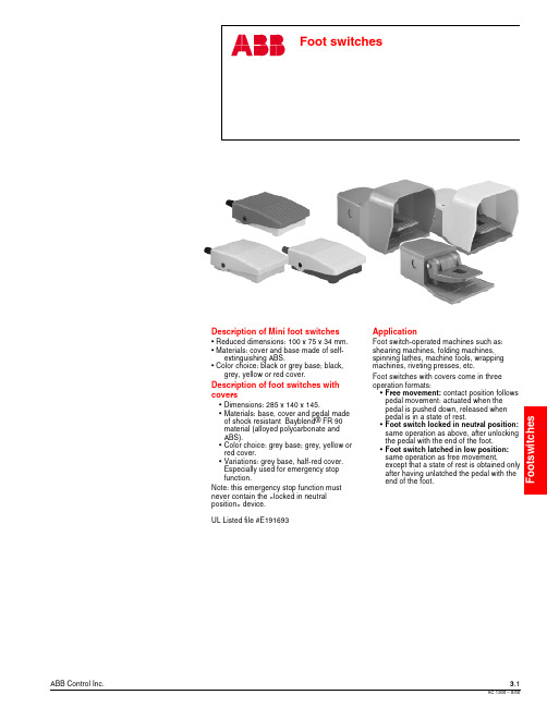
ABB Control Inc.3.18/00Description of Mini foot switches• Reduced dimensions: 100 x 75 x 34 mm.• Materials: cover and base made of self-extinguishing ABS.• Color choice: black or grey base; black,grey, yellow or red cover.Description of foot switches with covers•Dimensions: 285 x 140 x 145.•Materials: base, cover and pedal made of shock resistant Bayblend ® FR 90material (alloyed polycarbonate and ABS).•Color choice: grey base; grey, yellow or red cover.•Variations: grey base, half-red cover.Especially used for emergency stop function.Note: this emergency stop function must never contain the «locked in neutral position » device.UL Listed file #E191693ApplicationFoot switch-operated machines such as:shearing machines, folding machines,spinning lathes, machine tools, wrapping machines, riveting presses, etc.Foot switches with covers come in three operation formats:•Free movement: contact position follows pedal movement: actuated when the pedal is pushed down, released when pedal is in a state of rest.•Foot switch locked in neutral position:same operation as above, after unlocking the pedal with the end of the foot.•Foot switch latched in low position:same operation as free movement,except that a state of rest is obtained only after having unlatched the pedal with the end of the foot.3.2ABB Control Inc.8/00Foot switchesIPM Mini foot switches, IPS Foot switches with covers DescriptionComment: Foot switches with covers can be assembled on a plate and equipped with a transportation handle. Upon request, instead of thehandle an emergency stop button can be installed above a tube that allows for connection cable passage.ApplicationFoot switch-operated machines such as: shearing machines, folding machines, spinning lathes, machine tools, wrapping machines, riveting presses, etc.Foot switches with covers come in three operation formats:•Free movement: contact position follows pedal movement:actuated when the pedal is pushed down, released when pedal is in a state of rest.•Foot switch locked in neutral position: same operation as above, after unlocking the pedal with the end of the foot.•Foot switch latched in low position: same operation as free movement, except that a state of rest is obtained only after having unlatched the pedal with the end of the foot.Description of Mini foot switches• Reduced dimensions: 100 x 75 x 34 mm.• Materials: cover and base made of self-extinguishing ABS.• Color choice: black or grey base; black, grey, yellow or red cover.Description of foot switches with covers•Dimensions: 285 x 140 x 145.•Materials: base, cover and pedal made of shock resistant Bayblend ® FR 90 material (alloyed polycarbonate and ABS).•Color choice: grey base; grey, yellow or red cover.•Variations: grey base, half-red cover. Especially used forABB Control Inc.3.38/00Foot switches Mini foot switchesIPM Mini foot switchesIPM1RMini foot switch Cover color Y - yellow G - grey B - black R - redBase color 1 - black 2 - greyCatalog number explanationIPM1YIPM1YIPM1GIPM1BIPM1RDiscount schedule RM3.4ABB Control Inc.8/00Foot switchesFoot switches with coversIPS foot switchesTo select a foot switch color, substitute the appropriate color code for the 5 in the catalog numberColor codeYellowY Grey G RedRContact blocks11 - 1 N.O. contact + 1 N.C. contact 22 - 2 N.O. contacts + 2 N.C. contactsCover color Y - yellow G - grey R - redZ - half-red cover 11 - Free movement2 - Foot switch locked in neutral position3 - Foot switch latched in low positionA - Za Snap actionD - Zb Slow action non-overlapping late makePlain foot switch with cover Catalog number explanationIPS Y1 A 111Incompatible with locked in neutral position function.Discount schedule RMABB Control Inc.3.58/001 2 3510Current (A)Current (A)1 2 3 5100.2 0.30.5Technical data3.6ABB Control Inc.8/00Technical data Mini-footswitchesDimensions (mm )N.O. + N.C. Contact blockIPM Mini foot switchesABB Control Inc.3.78/00Technical dataFoot switches with coversDimensions (mm )Plain foot switch a = pre-travel b = total travelExample of double foot switch utilization。
ABB-Welcome IP HD1205-S 人脸识别门口机 用户手册说明书

2TMD042000D0044│ 08.02.2021产品手册ABB-Welcome IPHD1205-S 人脸识别门口机1使用说明 (4)2安全 (4)3按规定使用 (5)4环境 (6)4.1ABB设备 (6)5产品描述 (7)5.1外观 (7)5.2接口描述 (8)5.3锁类型与连接 (9)6技术参数 (10)7安装 (11)7.1对电工的要求 (11)7.2安装 (12)7.2.1准备 (12)7.2.2安装高度 (12)7.2.3嵌入安装 (14)7.2.4拆卸 (15)8设置 (16)8.1待机屏幕 (16)8.2进入“设置”页面 (17)8.3工程设置 (18)8.4门禁设置 (19)8.5系统设置 (20)9操作 (22)9.1呼叫室内机 (22)9.2呼叫管理中心 (22)9.3刷卡开锁 (22)9.4出门按钮开锁 (22)9.5密码开锁 (23)9.6人脸识别开锁 (24)10网络安全 (25)10.1免责声明 (25)10.2性能与服务 (25)10.3布防指南 (26)10.4升级 (26)10.5备份/恢复 (26)10.6恶意软件预防方案 (26)10.7密码规则 (26)注意事项 (27)1使用说明请仔细阅读本手册,并遵守其中所含的信息。
这将有助于避免人身伤害和财产损失,确保设备操作可靠且使用寿命长。
请将本手册保管在安全地方。
如果转让本设备,请一并提供本手册。
如未能遵守本手册的说明,ABB概不负责。
2安全警告电压!直接或间接接触导电部件会导致触电危险。
可能会造成电击,灼伤甚至死亡。
–安装和拆卸前应先切断电源!–仅可由专业人员来执行100 - 240 V电网上的工作。
3按规定使用该设备是 ABB-Welcome IP系统的一部分,必须与该系统的其他设备搭配使用。
安全模式该门口机默认在“安全模式”下工作,从而确保高度的安全性。
在“安全模式”下,该门口机需要上位机软件签发的证书才能正常运行。
电动门说明书

REV 13ETable of ContentsGeneral Safety (2)Preparation for Installation (3)Parts List (4)Optional Accessories Part List (5)Technical Specifications & Feature (5)Installation Overview (6)Installation of the Opener (6)Manual Operation (7)Installation of chain and chain brackets (7)Installation of Magnets for Limit Switches (9)Connecting Of Power Supply (10)Connecting of the Control Board (10)Setting of the Control Board (11)Test the reversing sensitivity (13)How to learn or erase the remote (13)How to use the remote to control the opener (13)Trouble Shooting (14)Maintenance (14)Thank you for purchasing our sliding gate opener. We are sure that the products will be greatly satisfying as soon as you start to use it.The product is supplied with a user’s manual which encloses installation and safety precautions. These should be read carefully before installation and operation as they provide important information about safety, installation, operation and maintenance. This product complies with the recognized technical standards and safety regulations.General SafetyWARNING! An incorrect installation or improper use of the product can cause damage to persons, animals or properties.• Scrap packing materials (plastic, cardboard, polystyrene etc.) according to the provisions set out by current standards. Keep nylon or polystyrene bags out of children’s reach.•This product was exclusively designed and manufactured for the use specified in the present documentation. Any other use not specified in this documentation could damage the product and be dangerous.• The factory declines all responsibility for any consequences resulting from improper use of the product, or use which is different from that expected and specified in the present documentation.• Do not install the product in explosive atmosphere.•The factory declines all responsibility for any consequences resulting from failure to observe Good Technical Practice when constructing closing structures (door, gates etc.), as well as from any deformation which might occur during use.• Disconnect the electrical power supply before carrying out any work on the installation. Also disconnect any buffer batteries, if fitted.• Fit an omnipolar or magnetothermal switch on the mains power supply, having a contact opening distance equal to or greater than 3,5 mm.• Make sure a residual current circuit breaker with a 30mA threshold is fitted before the power supply mains.• Check that earthing is carried out correctly: connect all metal parts for closure (doors, gates etc.) and all system components provided with an earth terminal.• Fit all the safety devices (photocells, electric edges etc.) which are needed to protect the area from any danger caused by squashing, conveying and shearing.• The factory declines all responsibility with respect to the automation safety and correct operation when other supplier’s components are used.• Only use original parts for any maintenance or repair operation.• Do not modify the automation components, unless explicitly authorized by the factory.• Instruct the product user about the control systems provided and the manual opening operation in case of emergency.• Do not allow persons or children to remain in the automation operation area.•Keep radio control or other control devices out of children’s reach, in order to avoid unintentional automation activation.• The user must avoid any attempt to carry out work or repair on the automation system, and always request the assistance of qualified personnel.• Anything which is not expressly provided for in the present instructions is not allowed.•Before installing the gate opener, check that all moving part as well as the sliding gate is in good mechanical condition, correctly balanced and opens and closes properly.•Save these instructions for future use.Preparation for InstallationBefore proceeding to your opener installation, check if your gate structure is in accordance with the current standards, especially as follows:The gate sliding track is linear and horizontal.The wheels are suitable for use. The gate should be mounted and moved freely. Check that the structure is sufficiently strong and rigid, and that its dimensions and weights conform to those listed in the specifications table of this document. Make sure that the gate is plumb and level. The fence posts must be mounted in concrete. The gate does not bind or drag on the ground.• The gate manual operation can be carried out smoothly along its entire run, and there is no excessive side slipping.• The opening and closing gate stops are positioned.WARNING: Remember that control devices are intended to facilitate gate operation, but can not solve problems due to any defects or deficiency resulting from failure to carry out correct installation or maintenance. Take the product out of its packing and inspect it for damage. Should it be damaged, contact your dealer. Remember to dispose of its components (cardboard, polystyrene, nylon, etc.) according to the current prescriptions.Refer to the following Figures for gate installation.In sake of safety, a positive stop must be mounted on the two end of ground track.Parts ListOptional Accessories Parts ListTechnical Specifications & FeaturesSpecificationsSCG 17 / AC 1500SCG 20 / AC 2400Power supply:120V/60Hz or 230V/50HzMotor voltage:120VAC or 230VACFrequency433.92MHzAbsorbed power:300W500WGate moving speed:15 cm/secondMax gate weight:600KGS/1500LBS1000KGS/2400LBSMax torque:12Nm24NmEnvironmental conditions:From -15°C to +40°CProtection class:IP44Dimensions:25.2×22×25 CMFeatures:·Midway mode.·Quick selection for the gate open/close direction·Reliable rolling code technology for remote control·Emergency release key in case of power failure·Stop/Reverse in case of obstruction during gate opening/closing·Built in adjustable auto-close·Built in motor running limitation: max. 90 sec ·Reliable electromagnetism limit for easy adjustment ·Can be equipped with a wide range accessories Installation OverviewInstallation of the Opener Caution:*Be sure that the opener is installed in a level and paralleled position and is properly secured. Improper installation could result in property damage, severe injury, and/or death.* Before starting installation, ensure that there is no point of friction during the entire movement of the gate and there is no danger of derailment. * Ensure that the safety side panels are present.Necessary Tools: The following tools may be necessary to install the Gate opener. You will need screwdrivers, an electric drill, wire cutters and a wire stripper, a socket set, and possibly access to a welder.When install the opener, you should build a concretepad to support the base plate of opener in order to maintain proper stability.The installation proceeds are as follows:1.Dig a hole for a concrete pad which should be approximately 60 x 32 x 35cm (24〞x13〞x14〞). It may protrude 10 cm (4”) above ground and 25 cm (10”) in depth underground. Increase the pad heightif necessary to protect the system from flooding, heavy snow etc.2.Prepare one or more conduits for the electrical cables before pour concrete. Remember that cable conduits have to pass through the hole in the base plate.3. Pour concrete and before it starts to harden, check that it is parallel to the gate leaf and perfectly level.4. The four anchor bolts must be set into the concrete when it is poured, make sure the position of anchor bolts was placed according to the position of mounting holes on the base plate before concrete become harden.5. Mount the base plate to the concrete Pad. It's only temporary installation. Further adjustment will be required when install the chain.6. Mount the chain box to the base plate by using screws and washers, don’t make the four screws too tight.Manual OperationThe opener should be put in the manual (emergency release) position before fitting the rack, installing the opener and limit switch.The process is as follows:1) Take off the rubber stopple.2) Insert the Release Key(provided)and turn it in counter-clockwise 180° to disengage the clutch between the gear shaft and power output. Now the opener is in the manual operation.Installation of chain and chain brackets1. Chain Brackets1). Please refer to below chain brackets figure,which shows “U” bolt, “L” bracket and chain bolt.Use the “U” bolts (square or round) to attach thechain brackets to gate frame.2). If Both the square bolts and round bolts are notfit for the gate frame, use the appropriate bolts toattach the chain brackets to gate frame.2. How to install the chain1). Place the chain around the top of the idlerwheels and under the drive sprocket in chain box.2). Connect a chain bolt to one end of chain fromchain box by using master link. Then insert the chain bolt to the L bracket and fix them each other bywashers and nuts temporarily. (Nuts will be further adjusted for a proper chain tension later)3). Connect second chain bolt with another end of chain from chain box, then attach bolt to the L bracket on opposite end of gate using the washers and nuts.4). Make sure that the chain is line up exactly with the position where the chain on the chain idler wheel.5). Get the desired chain tension by adjusting two chain bolts of the both end.Cut the unwanted length of chain if necessary.6). Fix the base plate by tightening the washers and nuts.7). Insert the opener shaft into the drive sprocket of chain box.Mount the opener by tightening the bolts and washers.8). Fix the chain box by tightening the four lax screws.* Thoroughly fasten the four nuts as well as spring washers onto anchor bolts tightly, enabling the opener is firmly secured on the concrete pad during the whole gate travel.3. Check position of opener and chain brackets1). The chain brackets must be mounted to the same height as the chain on the idler wheels.2). The opener must be parallel to the gate.3). Make sure there is 1” distance at least between the chain box and the gate after you position the base plate.Installation of Magnets for Limit SwitchesBefore install limit switch, make sure thegate opener is put in manual operation. (theclutch connected with gear shaft isdisengaged) and the mains power supply isdisconnected.Position the two Magnet Componentsapproximately on the gate and move thegate by hand to fix them in place.Fit magnets bracketPush the gate fully closed by hand. Locateand install the magnet bracket so that theopener will stop at the desired close positionwhen the close limit switch approaches it.Push the gate fully open by hand. Locateand install the magnet bracket so that theopener will stop at the desired open positionwhen the open limit switch approaches it.The magnet component with N pole outside must be installed at left side and the magnet component with S pole outside must be installed at right side from the view inside of property.Finally adjust the magnet to the proper position by moving the gate with the motor. The magnet should be less than 1“away from the magnetic limit switch. If it is too far away, the switch will fail to work. The distance between the magnet and the opener should be 0.39”- 0.59” with the opener cover on. Adjust the position of the magnet until the positions of the opening and closing meet the requirement.Connecting Of Power SupplyThe power supply cord should be at least 3×0.75mm2. Connect the live wire and neutral wire to the “L”(2) and “N”(1) terminal respectively; and connect the earth wire to“PE”.Connecting Of the Control Board1. MotorThe BLACK wire of the motor should be connected into the “3” terminal.The YELLOW wire of the motor should be connected into the “4” terminal.The RED wire of the motor should be connected into the “5” terminal.2. Limit SwitchesThe YELLOW wire of the limit switches should be connected into the “8” terminal.The BLACK wire of the limit switches should be connected into the “9” terminal.The RED wire of the limit switches should be connected into the “10” terminal.3. Alarm Lamp (Optional)One wire of the alarm lamp should be connected into the “6” terminal, another should be connected into the “7” terminal.4. Start CapacitorThe two wires of the start capacitor should be connected into the “4”terminal and “5” terminal.5. Photocell(Optional)Use a 2-core cable to connect the “+ ~” terminal of the photocell’s emitter to the “13” terminal, the “- ~”terminal to the “11”terminal. Also the “+ ~”and “- ~”terminals of the photocell’s receiver should be connected to the “13” and “11” terminals in parallel.Use another 2-core cable to connect the “COM”terminal of the receiver to the “13”terminal, the “NC”terminal to the “12” terminal.5. Wired Keypad (24VDC)The RED wire of the wired keypad should be connected into the “13” terminal.The BLACK wire of the wired keypad should be connected into the “11” terminal.The WHITE wire of the wired keypad should be connected into the “13” terminal.The BLUE wire of the wired keypad should be connected into the “14” terminal.6. Push Button (Optional)The push button should be wired to the “13” and “14”terminals. The gate operator works alternately by pushing the button (open-stop-close-stop-open).Setting Of the Control BoardWARNING: Keep away from the gate during you set the gate opener system in case of the unexpected gate moving. Carefully adjust the DIP switches to avoid the risk of machine damage and injury or death. Always ask the help of professional technician /electrician if you have any question.1.DIP SwitchesThe DIP switches are used to set the running time of the motor in pedestrian mode, enable/disable auto close function of the gate operator and fast change the open/close direction which is determined by the position of the gate operator installed.DIP Switch #1–#2: Running time of the motor in Midway ModeDIP Switch #1: ON –2 Seconds OFF –0DIP Switch #2: ON –4 Seconds OFF –0NOTE: The midway mode function would be disabled if both DIP switches are turned off.Factory default setting is disabled.DIP Switch #3: Auto close function enabled/disabledDIP Switch #3: ON –auto close function enabledOFF –auto close function disabledDIP Switch #4: Left/Right open2. PotentiometersPotentiometer A and B are used to adjust the stall force and auto close time of the gate operator separately. Turn potentiometer A clockwise to increase the stall force, and turn it counter-clockwise to decrease the stall force.Turn potentiometer B clockwise to increase the auto close time, and turn it counter-clockwise to decrease the auto close time, the auto close time could be adjusted steplessly from 1 to 99 seconds.E.g.Running time of the operator in pedestrian mode is 2seconds.E.g. Auto close function of the opener has been enabled. Factory default setting is disabled.Test the reversing sensitivityFor the sake of safety,it is very important to test the reversing sensitivity as soon as the control board set is finished.The reversing sensitivity adjustment is inverse correlation with stall force adjustment in potentiometer A and B.In other word, the stall force level is higher; the reversing sensitivity level is lower.Put an immobile object along the gate path, and then operate the gate to strike it during the open and close cycles. The gate must reverse as soon as object is struck with it. If the gate doesn’t reverse, please increase the reversing sensitivity by turning the potentiometer A in counter-clockwise direction. (Turning the stall force potentiometer toward to MIN position to increase the reversing sensitivity)Note 1: If the sensitivity setting is too higher, the gate will stop or reverses very easy by itself while there is little obstruction or resistance such as strong wind or heavy snow sometimes.Note 2: Always check the gate reversing function every each time of control board set or restart after power off.How to learn or erase the remoteLearn the remotePress and release the learn button, the LEARN LEDlight will be on,then press the key in the remote twicein 2 seconds, the LEARN LED light will flash for 4seconds. Now the remote has been learnt successfully.This control board can learn up to six remotes, if youwant to learn more, we recommend that you buy the external receiver(LM138).Erase all the remote codesPress and hold the learn button until the LEARN light is off. Now all remote codes have been erased.How to use the remote to control the operatorKey A is used to operate the operator to work alternately (open-stop-close-stop-open).When the Pedestrian Mode function is enabled, Key B is used to achieve thePedestrian Mode function (open the gate for the pre-setting time). When thePedestrian Mode function is disabled, the operator works alternately (open-stop-close-stop-open) by pressing Key B.TroubleshootingHave a multimeter to check voltage and continuity. Use caution when checking high voltage terminals.MaintenanceEvery six months check the following items for proper operation of the unit.*Lubricate shafts and sprockets.*Keep operator clean at all times.*Check and tighten anchors bolts.* Check for loose or corroded wire* Ensure the operator is well earthed, and correctly terminated.*Always check the Stop/Reverse in case of obstruction function when performing any maintenance.If this function can’t be made operable,remove this operator from service until the cause of the malfunction is identified and corrected.Symptom Possible Solution(s)The remote controldoes not emit any singleCheck the batteries are exhausted, replace them if necessary.The operator doesn’t run.1. Make sure that the power cord is properly plugged into the mains outlet.2. Check the fuse is blown in the control board; if necessary, identify thereason for the failure and then replace a new one.3. Make sure the photocell beam is not blocked if the photocell is used.Check the terminal 11 should be shorted with terminal 12 by a jumper wire.Please reset this jumper wire if it is loss.The gate starts but it is immediately stop or reverse 1. The selected force is too small to move the gate. Turn the Potentiometer clock-wise to increase the force.2. Disconnect the gate from the gate operator and check that the gate slides freely without any binding. 7106 S 220th St, Kent WA 98032 USA *****************************©2012-2014ALEKO All Rights Reserved。
ABB i-bus KNX 窗帘 滚动门驱动器-自动检测与手动操作x倍说明书
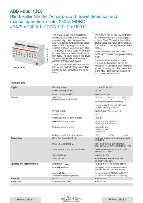
JRA/S x.230.5.1, 2CDG 110 12x R00112C D C 071 018 S 0011The 2-fold, 4-fold and 8-fold Blind/ Roller Shutter Actuators are used to automatically control independent 230 V AC drives, for positioning blinds, roller shutters, awnings and othershading products via ABB i-bus ® KNX. The devices are also used, for example , to control doors, windows and ventila-tion flaps. The travel times of the drives are automatically determined via end position detection and stored.The output contacts are mechanically interlocked, so that voltage cannot be applied to both contacts at the same time.The outputs can be directly controlled on the device using the manual push buttons. The LEDs on the front of the device signal the status of the outputs. The devices do not require an auxiliary voltage.Individual outputs can be copied or exchanged to reduce the programming effort.The Blind/Roller Shutter Actuator is a modular installation device for installation in the distribution board on 35 mm mounting rails. The connection to the ABB i-bus ® is implemented via bus connection terminals.JRA/S 8.230.5.1Technical dataButtons and LEDs Two buttons and LEDs per outputJRA/S x.230.5.1, 2CDG 110 12x R0011Device type ApplicationMaximum number of communication objects Maximum number of group addresses Maximum number of associations JRA/S 2.230.5.1Blind/Roller Shutter 2f 230V Travel Detection M/…*69255255JRA/S 4.230.5.1Blind/Roller Shutter 4f 230V Travel Detection M/…*129255255JRA/S 8.230.5.1Blind/Roller Shutter 8f 230V Travel Detection M/…*249255255* … = current version number of the application.Please observe the software information on our homepage for this purpose.Isolation categoryOvervoltage category Pollution degree III to EN 60 664-12 to EN 60 664-1KNX safety extra low voltage SELV 24 V DC Temperature rangeOperation Storage Transport-20 °C…+45 °C -25 °C…+55 °C -25 °C…+70 °CAmbient conditions Maximum air humidity93 %, no condensation allowed DesignModular installation device (MDRC)Dimensions (H x W x D) in mm; JRA/S Type – Height – Width – DepthMounting width in space units (modules at 18 mm)Mounting depthModular installation device, Pro M 2.230.5.1 4.230.5.18.230.5.190 90 90 72 72 144 64.564.564.54 4 8 64.5 64.5 64.5Weight without packaging JRA/S Type Weight in kg2.230.5.1 4.230.5.1 8.230.5.1 0.2 0.250.45Installation On 35 mm mounting rail To EN 60 715Mounting position As requiredHousing/colour Plastic housing, grey Halogen free Approvals KNX to EN 50 090-1, -2Certification CE markIn accordance with the EMC guideline andlow voltage guidelineJRA/S x.230.5.1, 2CDG 110 12x R0011Connection schematics JRA/S x.230.5.11 Label carrier2 LED3 Button4® KNX5 Button and LED 6(2 per output)78 Connection to ventilation flaps2C D C 072 036 F 00102C D C 072 034 F 0010Connection to the blind and roller shutter drivesJRA/S x.230.5.1, 2CDG 110 12x R0011Dimension drawing JRA/S x.230.5.12C D C 072 070 F 0010。
- 1、下载文档前请自行甄别文档内容的完整性,平台不提供额外的编辑、内容补充、找答案等附加服务。
- 2、"仅部分预览"的文档,不可在线预览部分如存在完整性等问题,可反馈申请退款(可完整预览的文档不适用该条件!)。
- 3、如文档侵犯您的权益,请联系客服反馈,我们会尽快为您处理(人工客服工作时间:9:00-18:30)。
Power Electronic Units for Field Installation 给现场装置供电使之能够工作EAN823, EBN853, EBN861 (Contrac) EAN823, EBN853, EBN861 (Contrac)For the Control of Contrac Actuatorsof the PME, LME, RHD or RSD Series PME, LME, RHD or RSD系列的Contrac激励的控制Content 目录1设备说明 (2)2 应用 (3)3 概要 (3)3.1 正确用法 (3)3.2 安全和预防 (3)4 存放4.1 长期存放 (3)5 交货设置 (3)6 汇编6.1 EAN823 / EBN853 (4)6.2 EBN861 (5)7 技术参数7.1 一般的…………………………………………………………………………………6 7.2 EAN823的电流消耗…………………………………………………………………67.3 EBN853的电流消耗…………………………………………………………………77.4 EBN861的电流消耗…………………………………………………………………77.5 保险丝…………………………………………………………………………………78 装备8.1 准备电.............................................................................................8 8.2 EAB823 / EBN853的装备 (8)8.3 EBN861的装备 (8)9 电路接线9.1 EAN823 / EBN853 / EBN861(标准的) (9)9.2 EAN823 / EBN853 / EBN861(现场总线数据处理)....................................9 9.3 电缆套管..........................................................................................10 9.4 输入 / 输出信号 (10)9.5 插头接线 (11)13 结构13.1 控制面板的结构(联接控制协议) (12)13.2 调节器所用的程序 (13)13.3 控制面板的功能和信号 (13)14 警告 / 故障14.1 解说 (15)14.2 警告摘要 (15)14.3 故障摘要 (16)15 故障及处理方法 (17)LegendDangerIndicates an imminently hazardous situation which, if not avoided, will result in death or serious injuryWarningIndicates a potentially hazardous situation which, if not avoided, could result in death or serious injury or serious property damage.CautionIndicates a potentially hazardous situation which, if not avoided, may result in minor or moderate injury or property damage.ImportantIndicates useful hints or other special informati on which, if not observed, could lead to a decline in operating convenience or affect the functionality.1.Device Identification 设备验证1.1 General 概述The ID labels of the power electronics are located both 设备名牌在本体(电源部分)标注带电位于底部两边on the base (power supply) and on the cover (electronics(电源)在盖子上面(电和盖子封面上。
and software memory) of the unit. As the base and cover和存储软件)个体底部和封面are considered as separate assemblies, they may have考虑过的单独的装配他们可以有本体和盖面单独生产然后装配,different serial numbers (F. no.).不同的编号它们可以有不同的编号。
1.2ID Label on the Base 1.2本体标签5.Delivery settings 移交细则0/100%内的动作用额定转距保持关闭状态配置功能线性;输入 :4 ... 20 mA功能远程位置调节器,参数输出 4 ... 20 mA数字输入数据输入跳闸手动/自动DI 2 / DI 3 manual control +/-手动控制Digital outputs: DO 1 ready to operate, DO 2/3 end position signalling数字输出准备好操作决定发信号的位置Range :Not adjusted (to be adjusted during commissioning)范围不调整(在试车期间调整)he configuration of your actuator may differ from the standard configuration specified above.从标准的清单上看你actuator的配置可以不同It can be called up for display using a notebook / PC and the related configuration program.它可以用笔记本/个人电脑陈列配置的表not with fieldbus communication.不要野外通讯6.Assemblies 装配Power electronics EAN823, EBN853 and EBN861 consist of 2 parts each, one containing theconnecting units (EAN823 and EBN853) and the transformer, the other containing the electronicsand the local control panel (LCP) for local operation and adjustment of the actuator.EAN823, EBN853 and EBN861的电源由两个相互独立的部分组成,一部分包含接头(EAN823 and EBN853)和变压器,另一部分包含就地控制面板用来现场操作和调试。
图片1:EAN823的电动部分图片2:EBN853的电动部分1 taphole for cable glands2 cover for connection chamber3 connection housing4 electronic hod5 cover for local control panel1 穿线孔2 接线盒3 固定部分4 电箱5 就地控制面板图3 :EAN823 / EBN853的接线盒The standard scope of delivery considers tapholes covered with srew-in plugs. Adapters for PG or NPT cable glands are available on request. 按标准交货时传闲空应该塞上。
配备合适的接头是很有用的。
接线盒电源保险信号端子接保险和加热器的端子电机端子 主保险总电源接线端子电缆接头穿线孔就地控制面板 盖用螺钉 连接螺钉变压器和电源连接螺钉盖用螺钉电器部分盖子电机电源线入口电机刹车 主电缆接线端子信号接线端子 信号电缆入口7.技术资料工作台 1PROFIBUS DP通讯不了7.2 Current Consumption of EAN823当前通用EAN823each around 各自周围7.5 Fuses 保险丝Electronic 保险类型安装地点U = 115 V U = 230 V 1) unitEAN823 外部保险外部16 A, 慢主保险接线盒内 6.3 A, 慢 3.15 A, 慢模拟量信号输入接线盒内40 mA; 快防潮加热器接线盒内 2 A; 慢EBN853 外部保险外部16 A, slow主保险接线盒内12.5 A, slow 10 A, slow模拟量信号输入接线盒内40 mA; fast刹车保险、动力板0.315 A, 中间时间间隔中间电路保险动力板10 A, 极快防潮加热器接线盒内 2 A; slowEBN861 外部保险外部35 A fuse-- 16 A 安全熔断刹车保险功率板上0.315 A,-- 中间有时间间隔中间电路保险功率板上 15 A, 中间有时间间隔The 35 A fuse and the thermal safety cutout (16 A) are included in the scope of delivery. They ensure safe operation for the special swiching conditions of power electronics EBN861. Note that the cable cross-sectional area between the fuse and the electronics must be at least 2.5.35A保险和安全熔断保险(16A)是包含在交货范围内的。
它们确保EBN861安全运行的专用保险。
注意:保险与电路的连接处必须保证至少2.5平方毫米。
7.5.1 External fuses for EBN861Apart from the internal fuses (see also 7.5), the EBN861 power electronic unit requires two additionalexternal fuses, which are supplied separately to the unit.7.5.1 EBN861的外部保险部分保险是国产的(同样是7.5),EBN861 电源需要两个外部保险,用来替换。
