Effect of tensile stress on microstructure evolution of Al-Cu-Mg-Ag alloys
Effects-of-nano-TiO2-on-strength-shrinkage-and-microstructure-of-alkali-activated-slag-pastes

Effects of nano-TiO 2on strength,shrinkage and microstructure of alkali activated slagpastesL.Y.Yang a ,Z.J.Jia a ,Y.M.Zhang a ,⇑,J.G.Dai ba School of Materials Science and Engineering,Jiangsu Key Laboratory of Construction Materials,Southeast University,Nanjing 211189,China bThe Department of Civil and Environmental Engineering,The Hongkong Polytechnic University,Hong Kong,Chinaa r t i c l e i n f o Article history:Received 21March 2014Received in revised form 19October 2014Accepted 27November 2014Available online 4December 2014Keywords:Alkali activated slag TiO 2Strength ShrinkageMicrostructurea b s t r a c tFor alkali-activated slag (AAS),high drying shrinkage is an obstacle which impedes its application as a construction material.In this investigation,nano-TiO 2was added to AAS,and its mechanical properties and shrinkage were tested to examine its effect on hardened alkali-activated slag paste (AASP).To under-stand the impact of nano-TiO 2on AASP at micro scale,FTIR,MIP and SEM were carried out.Experimental results indicate that the addition of nano-TiO 2to AAS enhances the mechanical strength,and decreases the shrinkage of AASP.FTIR and SEM results demonstrated that the addition of nano-TiO 2into the AASP accelerates its hydration process,resulting in more hydration products and denser structure.MIP results showed that the addition of nano-TiO 2reduces the total porosity of AASP and changes the pore structure.The porosity of 1.25–25nm mesopores,which is believed to be responsible for the high shrinkage of AASP,is remarkably reduced due to the addition of nano-TiO 2.Ó2014Elsevier Ltd.All rights reserved.1.IntroductionGround granulated blast furnace slag is a kind of latent hydrau-lic material which can be activated by alkaline solutions,such as water glass,NaOH,Na 2CO 3,and Na 2SO 4,to form solid mass pos-sessing high strength and good performance.Alkali-activated slag (AAS)has been found to have good resistance to sulfate [1],freeze–thaw cycles [2],acid attack [3],high temperature [4],chlo-ride attack [5,6],etc.However,the application of AAS so far is very limited because of its high drying shrinkage [7,8]and high rate of carbonation [9,10].Collins et al.[8]found that drying shrinkage of AAS concrete was about 3.33times higher than OPC concrete at 365d when exposed to environment of 23°C and 50%relative humidity (RH).Results from literature show that,the high drying shrinkage of AAS is due to the specific pore size distribution,especially mesopores [8,11,12]which are responsible for the micro-strain formed in hardened AASP.In addition,the hydration products in AAS are mainly amorphous C-S-H of low Ca/Si ratio [13,14].The absence of crystal phases like CH,one of the main hydration products of Portland cement,is thought to be responsi-ble for high drying shrinkage of AASP as well.Shrinkage when restrained may cause the cracking of concrete,and it is therefore of great importance to work out good solutions to control the shrinkage evolvement of AASP.Bakharev et al.[15]found that heat treatment could improve the early strength and reduce the drying shrinkage of AAS concrete.Collins et al.[16]used saturated blast furnace slag (BFS)to replace normal coarse aggre-gate and found the drying shrinkage reduced significantly and the compressive strength was improved in drying condition.Fang et al.[17]revealed that the use of magnesia remarkably reduces the shrinkage of AAS concrete when its dosage does not exceed 8%.Palacios et al.[18]showed that the use of shrinkage-reducing agent (SRA)reduces the shrinkage of AASP by up to 85%and 50%when exposed to 99%and 50%RH,respectively.Nano materials are new emerging materials in the field of civil engineering and have been utilized by some researchers to enhance the properties,such as mechanical strength,abrasion resistance,and impermeability,of Portland cement concrete [19].The commonly used nano materials in cement-based materials are nano-TiO 2[20–24],nano-Al 2O 3[19,25],and nano-SiO 2[26–29].Feng et al.[22]showed that with the addition of 0.9%nano-TiO 2,the flexural strength and compressive strength of cement pastes at 28d increases by 16.12%and 14.15%,respec-tively.The investigation into the microstructure by Feng et al.[24]demonstrated that the incorporation of TiO 2decreases the quantity of inner micro cracks in Portland cement paste.Nazari et al.[30]investigated the effect of nano-TiO 2on physical,thermal/10.1016/j.cemconcomp.2014.11.0090958-9465/Ó2014Elsevier Ltd.All rights reserved.⇑Corresponding author.E-mail addresses:yanglingyan1010@ (L.Y.Yang),ymzhang@ (Y.M.Zhang).and mechanical properties of concrete using blast furnace slag replacing OPC,showingthe formation of C-S-H gel and improves the Motivated by the possibilities of achieving with AAS,this investigation aims to usethe mechanical strength and shrinkage property slag paste(AASP).2.Experimental2.1.MaterialsS95slag with specific surface area of436m2 2.90g/cm3was used.Slag particles observed ular with sharp clear edges(Fig.1).The particle the slag,tested with laser granulometry,100l m with average particle size of11.86l chemical composition of slag is shown in TableA mixture of solid NaOH and liquid water alkali activator.NaOH was analytically pure Ms.(molar ratio of Na2O to SiO2)of liquid and the mass content of Na2O was9.7%.Nano-TiO2with particle size ranging from20 used in this study(Fig.3).To avoid thenano particles,all the nano-TiO2was dispersed by28kHz ultra-sonic wave in water(half of the total mixing water of AASP)for 10mins.After dispersion,theflocculation of nano-TiO2particles was mitigated,as shown in Fig.3(b)and(c).The dispersed nano-TiO2was then mixed into AASP in10min.2.2.Mix proportionsThe water/binder ratio of the AASP in this investigation was0.4, which was determined after comprehensively considering the workability and strength of AASP according to previous investiga-tions.Alkali activator with a Na2O concentration of4.0%(by mass of slag)and Ms.of1.2was used.The water in the activator and 20°C.Specimens were then cured in a room of20±3°C and 90%±5%RH.The compressive strength and theflexural strength of the AASPs were measured according to Chinese standard GB/T 17671-1999at the age of3d,7d and28d.3.2.ShrinkageShrinkage test was conducted according to Chinese standard JGJ 70-2009.AASPs for shrinkage test were cast in40Â40Â160mm steel moulds with two small copper pieces at both ends,serving as shrinkage detectors.Specimens were sealed with plasticfilm after casting,and demolded after24h room curing.Then the initial length along the longitudinal axis was immediately measured with micrometer caliper.Both reference group and TiO2group were then cured under two regimes,one at20±3°C and90±5%RH, the other at20±3°C and55±5%RH.The length change was mea-sured at1d,3d,7d,14d,28d and90d,respectively.3.3.MicrostructureThe samples for microstructure analysis were taken from the specimens cured in a room with20±3°C and90%±5%RH at dif-ferent ages.These samples were then immersed immediately in ethanol for5days and then dried for48h at60°C in order to stop the hydration of AASP.3.3.1.Fourier transform infrared spectroscopy(FTIR)FTIR was carried out to determine the chemical groups of hydration products,at the frequency range of4000–400cmÀ1.All the samples for this analysis were ground into powders smaller than75l m.3.3.2.Scanning electron microscopy(SEM)The morphology of hydration products was observed with Sirion Field emission scanning electron microscopy.The samples were coated with gold to enhance the conductivity.3.3.3.Mercury Intrusion Porosimetry(MIP)MIP was used to measure the cumulative porosity and pore size distribution of AASP.Samples for this measurement were cut into size of1–2cm.Fig.1.Morphology of slag under SEM.Fig.2.Particle size distribution of slag.2L.Y.4.Results4.1.Mechanical strengthThe mechanical strength of reference group and TiO2group AASP are given in Table3.It can be seen that the addition of TiO2enhanced both the compressive and theflexural strength of AASP.The compressive strength of TiO2group was approximately 10%,15%and9%higher than those of reference group at3d,7d and28d,respectively.Theflexural strengths of TiO2group were 25%,25%and38%higher than reference group at3d,7d and 28d,respectively,which thereby resulted in higher ratio offlexural to compressive strength of TiO2group.4.2.ShrinkageThe influence of curing regime on the shrinkage of reference group and TiO2group AASP are shown in Fig.4.It can be seen that when cured at a RH of90±5%,the shrinkage of reference group and TiO2group at90d reached approximately1650micro strain and1400micro strain,respectively.When the RH for curing was 55±5%,both group AASPs suffered significant drying shrinkage from the beginning of curing till90d.The drying shrinkage of ref-erence group and TiO2group at90d reached6400micro strain and 5080micro strain,respectively.It is noticed that the addition of TiO2in AASP decreased the shrinkage at both curing conditions. At90d,the reduction in shrinkage of the TiO2group was measured to be18%and27%,when the curing RH was selected to be90±5% and55±5%,respectively,in comparison with that of the reference group.Table4shows the relative shrinkage referring to the shrinkage value at90d.It can be found that when the curing RH was90±5%, 83–84%of the shrinkage took place within7days and95–98% within28days.After28days,the curves of both groups of AASPs tend to level off.When the curing RH was55±5%,only67–70% of the shrinkage happened within7days and89–93%within 28days.After28days,the curves keep on going up and do not level off even at90d.It is obvious that the drying process of AASP under55±5%RH lasts much longer than under90±5%RH,no matter nano-TiO2is utilized or not.These results demonstrate that the addition of0.5%nano-TiO2 enhanced the mechanical strength of AASPs,and decreased the shrinkage of AASP under20±3°C and90±5%or55±5%RH. Literature data[8,11–14]indicate that pore size distribution and characteristics of hydration products are the critical factors affect-ing the shrinkage in OPC and AASP.In the following text,FTIR,SEM and MIP were utilized to investigate the hydration products and(a) SEM image: without dispersion (b) SEM image: after dispersion(c) TEM image:after dispersionFig.3.Images of nano-TiO2particles.Table2Mix proportions of AASP(in mass).Sample W/B Ms Na2O(%)TiO2(%)Reference group0.4 1.2 4.00TiO2group0.4 1.2 4.00.5Table3Mechanical strength of AASP with and without TiO2.Reference group TiO2group3d7d28d3d7d28dCompressive strength,MPa23.4833.9157.5625.7639.1562.96 Flexural strength,MPa 6.1710.0012.587.7112.4617.32 Ratio offlexural-compressive strength0.2620.2950.2190.2990.3180.275L.Y.Yang et al./Cement&Concrete Composites57(2015)1–73the structure of AASP to reveal the influence of nano-TiO2from micro scale.4.3.FTIR resultsSince the hydration products of AASP are mainly amorphousS-H[13],FTIR was carried out to determine the hydration products and their relative quantity by differentiating the typical wave numbers and their transmittance.Fig.5shows the infrared spectra reference group and TiO2group AASPs cured under90±5%RH. The infrared spectra of reference group and TiO2group in corre-sponding curing time are very similar,except that the transmit-tance at particular wave numbers is different.The bands 3448cmÀ1and1654cmÀ1are related to O–H stretching and molecular water,respectively[13,31].Bands between1410cm and1490cmÀ1in sharp shape,and small band at876cmÀ1are associated to anti-symmetric stretching(m3)and out-of-plane bending(m2)modes of CO32Àions[32],which is the product result-ing from carbonation in air during sample preparation.Bands at 964cmÀ1and at457cmÀ1are due to anti-symmetric Si–O(Al) stretching vibrations(m3)and to in-plane Si–O bending vibrations (m2)in SiO4tetrahedra,respectively[31–33].Bands at700cmÀ1 are the result of silicon substitution by aluminum in the silicon-oxygen tetrahedron structure.These bands are attributed to C-S-H and/or C-A-S-H gel.Compared to the reference group,the transmittance of TiO2 group at1420cmÀ1,946cmÀ1and457cmÀ1is enhanced due to the addition of nano-TiO2.The higher transmittance of TiO2group at1420cmÀ1shows that more hydration products were carbon-ated than in reference group.From the higher transmittance at 946cmÀ1and457cmÀ1in TiO2group,it could be deduced that more hydration products like C-S-H and C-A-S-H were produced when nano-TiO2was added.C-S-H and C-A-S-H are known as rigid gel that contributes to the strength of cement-based materials.Therefore more C-S-H and C-A-S-H produced in TiO2group AASP account for its higher mechanical strength in comparison with the reference group.4.4.SEM observation resultsFTIR results revealed that there was no new type of hydration products produced when nano-TiO2was added to AASP,though the amount of hydration products increased.SEM was applied to further investigate the differences in micro structure between ref-erence group and TiO2group at3d,7d and28d in this investiga-tion.The typical pictures taken under SEM are shown in Fig.6.At3d,two typical types of morphology of hydration productsFig.4.Shrinkage of the AASPs with and without TiO2.Table4Relative shrinkage referring to90d shrinkage.90±5%RH55±5%RH7d/90d28d/90d7d/90d28d/90dReference group,%84957093TiO2group,%83986789Fig.5.Infrared spectra of AASP with and without TiO2(90±5%RH).Composites57(2015)1–7L.Y.Yang et al./Cement&Concrete Composites57(2015)1–75(a) Morphology of reference group at 3d: cracks in matrix (a1); reticular outerproducts (a2); rod like inner products (a3)(b) Morphology of TiO2group at 3d: less cracks in matrix (b1); reticular outerproducts (b2); rod like inner products (b3)(c) Morphology of reference group at 7d: cracks in matrix (c1); reticular outerproducts and cracks (c2); rod like inner products (c3)(d) Morphology of TiO2 group at 7d: matrix (d1); loose outer products (d2); rod likeinner products(d3)(e) Morphology of reference group at 28d: cracks in matrix (e1); loose outer productsand cracks (e2)(f) Morphology of TiO2 group at 28d: matrix (f1); dense and massive hydrationproducts (f2)SEM images of reference group and TiO2group at3d,7d and28d(90considerably reduced the width and number of micro cracks in AASP matrix.At 7d,the microstructures of both groups are much denser.For reference group,reticular C-S-H gel is still found,but the pore size is smaller than that at 3d,and micro cracks are formed across the porous C-S-H.For TiO 2group,reticular C-S-H seems to have disap-peared,granular C-S-H is however observed in originally water filled space.The structure of inner hydration products (originally rod like C-S-H area,as observed at 3d)of TiO 2group is more homogeneous than that in reference group as well.At 28d,AASPs for both groups have developed into solid mass at micro scale.Here again,the structure of TiO 2group is much den-ser than reference group,and much less cracks exist in TiO 2group.As far as the results from FTIR and SEM are concerned,the addi-tion of nano-TiO 2into AAS accelerated the hydration process,resulting in more hydration products like C-S-H and C-S-A-H,and more densified microstructure.This result is consistent with the enhanced mechanical strength of TiO 2group samples (cf.Section 4.1).4.5.MIP resultsMore quantitative results on the microstructure,particularly the pore structure of the two groups of AASPs were obtained from the MIP measurements.Fig.7shows the cumulative porosity of both reference group and TiO 2group from 3d to 28d tested with pared to the reference group,the TiO 2group had rela-tively lower total porosity,i.e.27.5%,24.5%and 19.8%at 3d,7d and 28d respectively,while the porosity in reference group was 31.6%,29.6%and 28.4%,respectively.According to Collins et al.[8],the total high porosity of pores within the mesopore region (1.25–25nm)in AASPs could explain their high magnitude of drying shrinkage.In Fig.7,the total poros-ity of AASPs is consisted of two parts,i.e.mesopores of 1.25–25nm and pores larger than 25nm.It can be seen that the addition of nano-TiO 2not only reduced the total porosity of AASP,but also remarkably changed the pore distribution.For the reference group,the porosity of 1.25–25nm pores was 28%,27%and 25.6%at 3d,7d and 28d,respectively.The corresponding value of TiO 2group was however much lower,being 14.9%,13.8%and 15.2%,respec-tively.When referring to the total porosity,the volume percentageof mesopores in reference AASPs was 91.1%,91.2%and 89.9%at 3d,7d and 28d,respectively.However,the corresponding value of TiO 2group was 54.3%,56.5%and 77.1%,respectively.When our MIP results are incorporated with the results of the shrinkage test in Section 4.2,consistence is obvious with the view of Collins et al.[8]and Tarek Aly et al.[11]that capillary tensile forces set up during drying is a very significant factor for the drying shrinkage of AAS.The relatively lower shrinkage of TiO 2group AASP could be explained by the much less amount of 1.25–25nm mesopores in the paste,when compared with the AASP without nano-TiO 2.It should be pointed out that the enhanced stiffness of AASP with nano-TiO 2,caused by the improvement of the mechanical strength,contributes to the decreased shrinkage to some extent as well,though the impact is not valuated in this paper.5.ConclusionsIn this investigation,0.5%(in mass)nano-TiO 2was added to alkali activated slag paste (AASP),and the mechanical properties,shrinkage,hydration products and microstructure of AASP were examined and compared with that of AASP without nano-TiO 2.The following conclusions are drawn.(1)The addition of nano-TiO 2into the AASP enhances the com-pressive and the flexural strength of the paste,and improves the flexural to compressive strength ratio as well.(2)The addition of nano-TiO 2into the AASP reduces the shrink-age of the paste cured under 20±3°C and 90±5%or 55±5%RH.Under 90±5%RH,the shrinkage curves tend to level off after 28days,but go up even till 90days under 55±5%RH.It should however be acknowledged that the shrinkage strain is still unacceptably large and further remedies are needed.(3)FTIR and SEM results demonstrated that the addition ofnano-TiO 2into the AASP accelerates its hydration process,resulting in more hydration products and denser structure.(4)MIP results showed that the addition of nano-TiO 2reducesthe total porosity of AASP and changes the pore structure.The porosity of 1.25–25nm mesopores,which is believed by previous researchers to be responsible for the high shrinkage of AASP,is remarkably reduced due to the addi-tion of nano-TiO 2.AcknowledgementsThe funding from the National Natural Science Foundation of China (project No.51378115)and 973project (2015CB655104)is greatly appreciated.The support from the Collaborative Innovation Center for Advanced Civil Engineering Materials is also acknowledged.References[1]Bakharev T,Sanjayan JG,Cheng YB.Sulfate attack on alkali-activated slagconcrete.Cem Concr Res 2002;32(2):211–6.[2]Fu Y,Cai L,Yonggen W.Freeze–thaw cycle test and damage mechanics modelsof alkali-activated slag concrete.Constr Build Mater 2011;25(7):3144–8.[3]Bakharev T,Sanjayan JG,Cheng YB.Resistance of alkali-activated slag concreteto acid attack.Cem Concr Res 2003;33(10):1607–11.[4]Pawlasova S,Skavara F.High-temperature properties of geopolymer materials.Alkali activated materials-research,production and utilization 3rd conference,Prague;2007.p.523–4.[5]El-Didamony H,Amer AA,Abd Ela-ziz H.Properties and durability of alkali-activated slag pastes immersed in sea water.Ceram Int 2012;38(5):3773–80.[6]Shi C.Corrosion resistance of alkali-activated slag cement.Adv Cem Res2003;15(2):77–81.[7]Chi M,Chang J,Huang R.Strength and drying shrinkage of alkali-activated slagpaste and mortar.Adv Civil Eng 2012;2012:7.Fig.7.Cumulative porosity of the AASPs (90±5%RH).Composites 57(2015)1–7[8]Collins F,Sanjayan JG.Effect of pore size distribution on drying shrinking ofalkali-activated slag concrete.Cem Concr Res2000;30(9):1401–6.[9]Palacios M,Puertas F.Effect of carbonation on alkali-activated slag paste.J AmCeram Soc2006;89(10):3211–21.[10]Palacios M,Puertas F,Vázquez T.Carbonation process of alkali-activated slagmortars.J Mater Sci2005;41:3071–82.[11]Aly T,Sanjayan J.Mechanism of early age shrinkage of concretes.Mater Struct2009;42(4):461–8.[12]Hansen T.Drying shrinkage of concrete due to capillary action.Matériaux etConstruction1969;2(1):7–9.[13]Lecomte I,Henrist C,Liégeois M,Maseri F,Rulmont A,Cloots R.(Micro)-structural comparison between geopolymers,alkali-activated slag cement and Portland cement.J Euro Ceram Soc2006;26(16):3789–97.[14]Tennis PD,Jennings HM.A model for two types of calcium silicate hydrate inthe microstructure of Portland cement pastes.Cem Concr Res2000;30(6): 855–63.[15]Bakharev T,Sanjayan JG,Cheng YB.Effect of elevated temperature curing onproperties of alkali-activated slag concrete;1999.p.0008–8846.[16]Collins F,Sanjayan JG.Strength and shrinkage properties of alkali-activatedslag concrete containing porous coarse aggregate.Cem Concr Res1999;29(4): 607–10.[17]Fang YH,Liu JF,Chen YQ.Effect of magnesia on properties and microstructureof alkali-activated slag cement.Water Sci Eng2011;4(4):463–9.[18]Palacios M,Puertas F.Effect of shrinkage-reducing admixtures on theproperties of alkali-activated slag mortars and pastes.Cem Concr Res 2007;37(5):691–702.[19]Rashad AM.A synopsis about the effect of nano-Al2O3,nano-Fe2O3,nano-Fe3O4and nano-clay on some properties of cementitious materials–a short guide for Civil Engineer.Mater Des2013;52:143–57.[20]Chen J,Kou SC,Poon CS.Hydration and properties of nano-TiO2blendedcement composites.Cem Concr Compos2012;34(5):642–9.[21]Nazari A,Riahi S.The effects of TiO2nanoparticles on physical,thermal andmechanical properties of concrete using ground granulated blast furnace slag as binder.Mater Sci Eng:A2011;528(4–5):2085–92.[22]Feng LC,Gong CW,Wu YP,Feng DC,Xie N.The study on mechanical propertiesand microstructure of cement paste with nano-TiO2.Adv Mater Res 2013;629:477–81.[23]Jalal M,Fathi M,Farzad M.Effects offly ash and TiO2nanoparticles onrheological,mechanical,microstructural and thermal properties of high strength self compacting concrete.Mech Mater2013.[24]Feng D,Xie N,Gong C,Leng Z,Xiao H,Li H,et al.Portland cement pastemodified by TiO2nanoparticles:a microstructure perspective.Ind Eng Chem Res2013;52(33):11575–82.[25]Nazari A,Sh R,Shamekhi SF,Khademno A.Influence of Al2O3nanoparticles onthe compressive strength and workability of blended concrete.J Am Sci 2010;6(5):6–9.[26]Nazari A,Riahi S.Splitting tensile strength of concrete using groundgranulated blast furnace slag and SiO2nanoparticles as binder.Energy Build 2011;43(4):864–72.[27]Senff L,Labrincha JA,Ferreira VM,Hotza D,Repette WL.Effect of nano-silica onrheology and fresh properties of cement pastes and mortars.Constr Build Mater2009;23(7):2487–91.[28]Hou PK,Kawashima S,Wang KJ,Corr DJ,Qian JS,Shah SP.Effects of colloidalnanosilica on rheological and mechanical properties offly ash-cement mortar.Cem Concr Compos2012.[29]Gao K,Lin KL,Wang D,Hwang CL,Anh Tuan BL,Shiu HS,et al.Effect of nano-SiO2on the alkali-activated characteristics of metakaolin-based geopolymers.Constr Build Mater2013;48:441–7.[30]Nazari A,Riahi S.TiO2nanoparticles’effects on properties of concrete usingground granulated blast furnace slag as binder.Sci China Technol Sci 2011;54(11):3109–18.[31]Puertas F,Palacios M,Manzano H,Dolado JS,Rico A,Rodriguez J.A model forthe C-A-S-H gel formed in alkali-activated slag cements.J Euro Ceram Soc 2011;31(12):2043–56.[32]Yu P,Kirkpatrick RJ,Poe B,McMillan PF,Cong X.Structure of calcium silicatehydrate(C-S-H):near-,mid-,and far-infrared spectroscopy.J Am Ceram Soc 1999;82(3):742–8.[33]Ismail I,Bernal SA,Provis JL,San Nicolas R,Hamdan S,van Deventer JSJ.Modification of phase evolution in alkali-activated blast furnace slag by the incorporation offly ash.Cem Concr Compos2014;45(0):125–35.[34]Gebregziabiher BS,Thomas R,Peethamparan S.Very early-age reactionkinetics and microstructural development in alkali-activated slag.Cem Concr Compos2015;55:91–102.L.Y.Yang et al./Cement&Concrete Composites57(2015)1–77。
Effect of heat treatment on microstructure and

Effect of heat treatment on microstructure andtensile properties of A356 alloysPENG Ji-hua1, TANG Xiao-long1, HE Jian-ting1, XU De-ying21. School of Materials Science and Engineering, South China University of Technology,Guangzhou 510640, China;2. Institute of Nonferrous Metal, Guangzhou Jinbang Nonferrous Co. Ltd., Guangzhou 510340, ChinaReceived 17 June 2010; accepted 15 August 2010Abstract: Two heat treatments of A356 alloys with combined addition of rare earth and strontium were conducted. T6 treatment is a long time treatment (solution at 535 °C for 4 h + aging at 150 °C for 15 h). The other treatment is a short time treatment (solution at 550 °C for 2 h + aging at 170 °C for 2 h). The effects of heat treatment on microstructure and tensile properties of the Al-7%Si-0.3%Mg alloys were investigated by optical microscopy, scanning electronic microscopy and tension test. It is found that a 2 h solution at 550 °C is sufficient to make homogenization and saturation of magnesium and silicon in Į(Al) phase, spheroid of eutectic Si phase. Followed by solution, a 2 h artificial aging at 170 °C is almost enough to produce hardening precipitates. Those samples treated with T6 achieve the maximum tensile strength and fracture elongation. With short time treatment (ST), samples can reach 90% of the maximum yield strength, 95% of the maximum strength, and 80% of the maximum elongation.Key words: Al-Si casting alloys; heat treatment; tensile property; microstructural evolution1 IntroductionThe aging-hardenable cast aluminum alloys, such as A356, are being increasingly used in the automotive industry due to their relatively high specific strength and low cost, providing affordable improvements in fuel efficiency. Eutectic structure of A390 can be refined and its properties can be improved by optimized heat treatment [1]. T6 heat treatment is usually used to improve fracture toughness and yield strength. It is reported that those factors influencing the efficiency of heat treatment of Al-Si hypoeutectic alloys include not only the temperature and holding time [2], but also the as-cast microstructure [3í5] and alloying addition [6í8]. Some T6 treatment test method standards of A356 alloys are made in China, USA, and Japan, and they are well accepted. However, they need more than 4 h for solution at 540 °C, and more than 6 h for aging at 150 °C, thus cause substantial energy consumption and low production efficiency. It is beneficial to study a method to cut short the holding time of heat treatment.The T6 heat treatment of Al-7Si-0.3 Mg alloy includes two steps: solution and artificial aging; the solution step is to achieve Į(Al) saturated with Si and Mg and spheroidized Si in eutectic zone, while the artificial aging is to achieve strengthening phase Mg2Si. Recently, it is shown that the spheroidization time of Siis dependant on solution temperature and the original Si particle size [9í11]. A short solution treatment of 30 minat 540 or 550 °C is sufficient to achieve almost the same mechanical property level as that with a solution treatment time of 6 h [12]. From thermal diffusion calculation and test, it is suggested that the optimum solution soaking time at 540 °C is 2 h [13]. The maximum peak aging time was modeled in terms of aging temperature and activation energy [14í15]. According to this model, the peak yield strength of A356 alloy could be reached within 2í4 h when aging at 170 °C. However, few studies are on the effect of combined treatment with short solution and short aging.In our previous study, it was found that the microstructure of A356 alloy could be optimized by the combination of Ti, B, Sr and RE, and the eutecticFoundation item: Project (2008B80703001) supported by Guangdong Provincial Department of Science and Technology, China; Project (09A45031160) supported by Guangzhou Science and Technology Commission, China; Project (ZC2009015) supported by Zengcheng Science andTechnology Bureau, ChinaCorresponding author: PENG Ji-hua; Tel/Fax: +86-20-87113747; E-mail: jhpeng@DOI: 10.1016/S1003-6326(11)60955-2PENG Ji-hua, et al/Trans. Nonferrous Met. Soc. China 21(2011) 1950í1956 1951melting peak temperature was measured to be 574.4 °Cby differential scanning calorimetry (DSC) [16]. In this study, using this alloy modified together with Sr and RE, the effect of different heat treatments on the microstructure and its mechanical properties were investigated.2 ExperimentalCommercial pure aluminum and silicon were melted in a resistance furnace. The alloy was refinedusing Al5TiB master alloy, modified using Al-10Sr andAl-10RE master alloys. The chemical composition ofthis A356 alloy ingot (Table 1) was checked by readingspectrometer SPECTROLAB. Before casting, the hydrogen content of about 0.25 cm 3 per 100 g in the meltwas measured by ELH-III (made in China). Four bars of50 mm×70 mm×120 mm were machined from the sameingot and heat-treated according to Table 2. Followed thesolution, bars were quenched in hot water of 70 °C.Samples cut from the cast ingot and heat-treated barswere ground, polished and etched using 0.5% HF agent.Optical microscope Leica í430 and scanning electricmicroscope LEO 1530 VP with EDS (Inca 300) wereused to examine the microstructure and fractograph. Toquantify the eutectic Si morphology change of differentheat treatments, an image analyzer Image-Pro Plus 6.0 was used, and each measurement included 800í1200 particles. Table 1 Chemical composition of A356 modified with Ti, Sr and RE (mass fraction, %) Si Cu Fe Mn Mg Ti Zn RE Sr 6.85 <0.01 0.19 <0.01 0.370.23 0.03 0.250.012Table 2 Heat treatments in this study Solution Aging Treatment Temperature/ °C Holding time/h Temperature/°C Holdingtime/hST 550r 5 2 170 2T6 535r 5 4 150 15 Tensile specimens were machined from the heat treated bars. The tensile tests were performed using a screw driven Instron tensile testing machine in air at room temperature. The cross-head speed was 1 mm/min. The strain was measured by using an extensometer attached to the sample and with a measuring length of 50mm. The 0.2% proof stress was used as the yield stressof alloys. Three samples were tested for each heat treatment to calculate the mean value.3 Results and discussion3.1 Microstructural characterization of as-cast alloyThe microstructure of as-cast A356 alloy is shown in Fig. 1(a). It is shown that not only the primary Į(Al) dendrite cell is refined, but also the eutectic silicon is modified well. By means of the image analysis, microstructure parameters of as-cast A356 alloy were analyzed statistically as follows: Į(Al) dendrite cell sizeis 76.1 ȝm, silicon particle size is 2.2 ȝm×1.03 ȝm (length×width), and the ratio aspect of silicon is 2.13. The distributions of RE (mish metal rare earth, more than 65% La among them), Ti, Mg, and Sr in the area shown in Fig. 1(b) are presented in Figs. 1(c)í(f)respectively. It is shown that the eutectic silicon particle is usually covered with Sr, which plays a key role in Siparticle modification; Ti and RE present generallyuniform distribution over the area observed, although alittle segregation of RE is observed and shown by arrowin Fig. 1(d). It is suggested that because the refiner TiAl 3and TiB 2 are covered with RE, the refining efficiency isimproved significantly. In the as-cast alloy, some clustersof Mg probably indicate that coarser Mg 2Si phases exist(arrow in Fig. 1(d))).Ti solute can limit the growth of Į(Al) primarydendrite because of its high growth restriction factor [17].The impediment of formation of poisoning Ti-Si compound around TiAl 3 [18] and promotion of Ti(Al 1íx Si x )3 film covering TiB 2 [19] are very important in Al-Si alloy refining. For Al-Si alloys, the effect of RE on the refining efficiency of Ti and B can be contributed to the following causes [20]: preventing refiner phases from poisoning; retarding TiB 2 phase to amass and sink;promoting the Ti(Al, Si)3 compound growth to cover theTiB 2 phase. In this work, with suitable addition of Reand Sr, the microstructure of A356 alloy was optimized. Especially, eutectic Si is modified fully, which isbeneficial to promote Si to spheroidize further duringsolution treatment. 3.2 Microstructural evolution during heat treatmentThe microstructures of A356 alloys treated withsolution at 550 °C for 2 h and ST treatment are presented in Figs. 2(a) and (b) respectively, while those treatedwith solution at 535 °C for 4 h and T6 treatment are presented in Figs. 2(c) and (d), respectively. From Fig. 1 and Fig. 2, after different heat treatments, the primary Į(Al) has been to some extent and the eutectic silicon has been spheroidized further. Both ST and T6 treatmentsproduce almost the same microstructure. The eutectic Si particle distribution and statistical mean aspect ratio of eutectic Si particle are shown in Fig. 3. After onlysolution at 535 °C for 4 h and 550 °C for 2 h, the meanPENG Ji-hua, et al/Trans. Nonferrous Met. Soc. China 21(2011) 1950í19561952Fig. 1 SEM images (a, b), and EDS mapping from (b) for Ti (c), La (d), Mg (e) and Sr (f) in as-cast alloyFig. 2 Microstructure of A356 alloy with different heat treatments: (a) Solution at 550 °C for 2 h; (b) ST treatment; (c) Solution at 535 °C for 4 h; (d) T6 treatmentPENG Ji-hua, et al/Trans. Nonferrous Met. Soc. China 21(2011) 1950í1956 1953Fig. 3 Statistic analysis of eutectic Si in A356 alloy with different heat treatmentsaspect ratios of Si are 1.57 and 1.54 respectively. After being treated by ST and T6, those aspect ratios of Si do not vary greatly, and they are 1.49 and 1.48, respectively. After solution or solution + aging in this study, the friction of eutectic Si particles with aspect ratio of 1.5 is 50%.The eutectic melting onset temperature of Al-7Si-Mg was reported to be more than 560 °C [16, 19]. 550 °C is below the liquid +solid phase zone. During solution, two steps occur simultaneously, i.e., the formation of Al solution saturated with Si and Mg, and spheroidization of fibrous Si particle. The following model predicts that disintegration and spheroidization of eutectic silicon corals are finished at 540 °C after a few minutes (IJmax ) [9]:2maxs 32ʌ..ln 9kT D U UW JI I§· ¨¸©¹ (1) where I denotes the atomic diameter of silicon; Ȗ symbolizes the interfacial energy of the Al/Si interface; ȡ is the original radius of fibrous Si; D s is the inter-diffusion coefficient of Si in Al; and T is the solution temperature. When the D s variation at different temperatures is taken into account, it is plausible to suggest that IJmax at 550 °C is less than IJmax at 540 °C. From Fig. 2(a), it is actually proved that spheroidization of eutectic Si particle could be finished within 2 h when solution at 550 °C.In a selected area of A356 alloy treated with only solution at 550 °C for 2 h (Fig. 4(a)), the distribution of element Mg is presented in Fig. 4(b). Because there is no cluster of Mg in Fig. 4(b), it means a complete dissolution of Si, Mg into Al dendrite during this solution. From the microstructure of A356 alloy treated with T6 (Fig. 5(a)), the distribution of Mg is shown in Fig. 5(b).Fig. 4 SEM image (a) and EDS mapping (b) of Mg distribution in alloy after only solution at 550 °C for 2 hFig. 5 SEM image (a) and EDS mapping of Mg (b) in alloy after heat treatment with T6For A357 alloy with dendrite size of 240 ȝm, uniform diffusion and saturation of Mg in Al could be finished at 540 °C within 2 h [13]. In this study, the cellPENG Ji-hua, et al/Trans. Nonferrous Met. Soc. China 21(2011) 1950í1956 1954size of primary Į(Al) is less than 100 ȝm. It is reasonable that those solutions treated at 535 °C for 4 h and 550 °C for 2 h, can achieve Į(Al) solid solution saturated with Mg and Si because diffusion route is short, even at a higher solution temperature.During aging, Si and Mg2Si phase precipitation happened in the saturated solid solution of Į(Al) according to the sequence in the Al-Mg-Si alloys with excess Si [21]. The needle shaped Mg2Si precipitation was observed to be about 0.5 ȝm in length and less than 50 nm in width, and the silicon precipitates were mainly distributed in Į(Al) dendrites and few of them could be observed in the eutectic region [22]. Because of the small size, these precipitations could not be observed by SEM in this study. However, it is plausible to suggest that the distribution of Mg in dendrite Al cell zone and eutectic zone is uniform (Fig. 4(b) and 5(b)). According to the study by ROMETSCH and SCHAFFER [15], the time to reach peak yield is 2í4 h and 12í14 h at 170 °C and 150 °C, respectively. From 150 to 190 °C of aging temperature, the peak hardness varies between HB110 and HB120. Hence, it is believed that aging at 170 °C for 2 h produces almost the same precipitation hardening as aging at 150 °C for 15 h.3.3 Tensile properties of A356 alloysThe tensile mechanical properties of A356 alloys are given in Table 3. Due to the microstructure optimization of A356 alloy by means of combination of refining and modification, tensile strength and fracture elongation can reach about 210 MPa and 3.7% respectively. Using T6 treatment in this study, strengthand elongation can be improved significantly. For those samples with T6 treatment, the tensile strength and ductility present the maximum values. 90% of the maximum yield strength, 95% of the maximum ultimate strength, and 80% of the maximum elongation can be reached for samples treated by ST treatment. However,T6 treatment spends about 19 h, while ST treatment takes only about 4 h. Fractographs of samples treated with T6 are presented in Fig. 6. The dimple size is almost similar with different heat treatments, indicating that the size and spacing of eutectic silicon particle vary little with different heat treatments. Shrinkage pore, microcrack inside the silicon particle and crack linkage between eutectic silicon particles were observed on the fracture surfaces.Table 3 Tensile properties of A356 alloys with different heat treatmentsHear treatmentıb/MPa ı0.2/MPa į/% As-cast 210 í 3.7 ST 247 178 5.6T6 255 185 7.0Fig. 6 Fractographs of samples with different heat treatments: (a), (b) T6; (c), (d) STPENG Ji-hua, et al/Trans. Nonferrous Met. Soc. China 21(2011) 1950í1956 1955It is well known that shrinkage pores have a great effect on the tensile strength and ductility of A356 alloys. In-situ SEM fracture of A356 alloy indicates the fracture sequence as follows [4]: micro-crack initiation inside silicon particle; formation of slipping band in the Al dendrite; linkage between the macro-crack and micro-crack, and the growth of crack. During tensile strain, inhomogeneous deformation in the microstructure induces internal stresses in the eutectic silicon and Fe-bearing intermetallic particles. Although the full modification of eutectic Si particle was reached in this study, those samples treated with T6 treatment do not perform as well as expected. The main reason is probably due to the higher gas content (0.25 cm3 per 100 g Al). Our next step is to develop a new means to purify the Al-SI alloys to further improve their mechanical properties.4 Conclusions1) The solution at 535 °C for 4 h and the solution at 550 °C for 2 h can reach full spheroidization of Si particle, over saturation of Si and Mg in Į(Al). The heat treatments of T6 and ST produce almost the same microstructure of A356 alloy.2) After both T6 and ST treatments, the aspect ratio of eutectic Si particle will be reduced from 2.13 to less than 1.6, and the friction of eutectic Si particles with aspect ratio of 1.5 is 50%.3) The T6 treatment can make the maximum strength and fracture elongation for A356 alloy. After ST treatment, 90% of the maximum yield strength, 95% of the maximum ultimate strength, and 80% of the maximum elongation can be achieved.References[1]WAN Li, LUO Ji-rong, LAN Guo-dong, LIANG Qiong-hua.Mechanical properties and microstructures of squeezed and casthypereutectic A390 alloy [J]. Journal of Huazhong University ofScience and Technology: Natural Science Edition, 2008, 36(8):92í95. (in Chinese)[2]RAINCON E, LOPEZ H F, CINEROS H. Temperature effects on thetensile properties of cast and heat treated aluminum alloy A319 [J].Mater Sci Eng A, 2009, 519(1í2): 128í140.[3]MANDAL A, CHAKRABORTY M, MURTY B S. Ageingbehaviour of A356 alloy reinforced with in-situ formed TiB2particles [J]. Mater Sci Eng A, 2008, 489(1í2): 220í226.[4]LEE K, KWON Y N, LEE S. Effects of eutectic silicon particles ontensile properties and fracture toughness of A356 aluminum alloysfabricated by low-pressure-casting, casting-forging, and squeeze-casting processes [J]. J Alloys Compounds, 2008, 461(1í2):532í541. [5]VENCL A, BOBIC I, MISKOVIC Z. Effect of thixocasting and heattreatment on the tribological properties of hypoeutectic Al-Si alloy[J]. Wear, 2008, 264 (7í8): 616í623.[6]BIROL Y. Response to artificial ageing of dendritic and globularAl-7Si-Mg alloys [J]. J. Alloys Compounds, 2009, 484(1): 164í167. [7]TOKAJI K. Notch fatigue behaviour in a Sb-modifiedpermanent-mold cast A356-T6 aluminium alloy [J]. Mater Sci Eng A,2005, 396(1í2): 333í340.[8]KLIAUGA A M, VIEIRA E A, FERRANTE M. The influence ofimpurity level and tin addition on the ageing heat treatment of the356 class alloy [J]. Mater Sci Eng A, 2008, 480(1í2): 5í16.[9]OGRIS E, WAHLEN A, LUCHINGER H, UGGOWITZER P J.Onthe silicon spheroidization in Al-Si alloys [J]. J Light Metals, 2002,2(4): 263í269.[10]SJOLANDER E, SEIFEDDINE S. Optimisation of solutiontreatment of cast Al-Si-Cu alloys [J]. Mater Design, 2010, 31(s1):s44ís49.[11]LIU Bin-yi, XUE Ya-jun. Morphology transformation of eutectic Siin Al-Si alloy during solid solution treatment [J]. Special Casting &Nonferrous Alloys, 2006, 26 (12): 802í805. (in Chinese)[12]ZHANG D L, ZHENG L H, STJOHN D H. Effect of a short solutiontreatment time on microstructure and mechanical properties ofmodified Al-7wt.%Si-0.3wt.%Mg alloy [J]. J Light Metals, 2002,2(1): 27í36.[13]YU Z, ZHANG H , SUN B, SHAO G. Optimization of soaking timefor T6 treatment of aluminium alloy [J]. Heat Treatment, 2009, 24(5):17í20. (in Chinese)[14]ESTEY C M, COCKCROFT S L, MAIJER D M, HERMESMANNC. Constitutive behavior of A356 during the quenching operation [J].Mater Sci Eng A, 2004, 383(2): 245í251.[15]ROMETSCH P A, SCHAFFER G B. An age hardening model forAl-7Si-Mg casting alloys [J]. Mater Sci Eng A, 2002, 325(1í2):424í434.[16]TANG Xiao-long, PENG Ji-hua, HUANG Fang-liang, XU De-ying,DU Ri-sheng. Effect of mishmetal RE on microstructures of A356alloy [J]. The Chinese Journal of Nonferrous Metals, 2010, 20(11):2112í2117. (in Chinese)[17]EASTON M A, STJHON D H. A Model of grain refinementincorporation alloy constitution and potency of heterogeneous nucleant particles [J]. Acta Mater, 2001, 49(10): 1867í1878.[18]QIU D, TAYLOR J A, ZHANG M X, KELLY P M. A mechanismfor the poisoning effect of silicon on the grain refinement of Al-Sialloys [J]. Acta Mater, 2007, 55(4): 1447í1456.[19]JUNG H, MANGELINK-NOEL N, BERGMAN C, BILLIA B.Determination of the average nucleation undercooling of primaryAl-phase on refining particles from Al-5.0wt% Ti-1.0wt% B inAl-based alloys using DSC [J]. J Alloys Compounds, 2009, 477(1í2):622í627.[20]LAN Ye-feng, GUO Peng, ZHANG Ji-jun. The effect of rare earthon the refining property of the Al-Ti-B-RE intermediate alloy [J].Foundry Technology, 2005, 26(9): 774í778. (in Chinese)[21]EDWARDS G A, STILLER K, DUNLOP G L, COUPER M J. Theprecipitation sequence in Al-Mg-Si alloys [J]. Acta Mater, 1998,46(11): 3893í3904.[22]RAN G, ZHOU J E, WANG Q G. Precipitates and tensile fracturemechanism in a sand cast A356 aluminum alloy [J]. J Mater ProcessTechnol, 2008, 207(1): 46í52.PENG Ji-hua, et al/Trans. Nonferrous Met. Soc. China 21(2011) 1950í19561956⛁ ⧚ A356䪱 䞥㒘㒛㒧 㛑ⱘ1ē 1ē 1ē ԃ 21. ⧚ ⾥ Ϣ 䰶ˈ 510640˗2. 䞥䙺 㡆 䞥 䰤 㡆䞥 ⷨお ˈ 510340㽕˖⫼ϸ⾡ϡ ⱘ⛁ ⧚ ⿔ 䬊㓐 㒚 䋼ⱘA356 䞥䖯㸠 ⧚ˈϔ⾡ 䭓 䯈 ⧚ T6(535 °C ⒊4 h+150 °C 15 h)ˈ ϔ⾡ ⷁ 䯈ⱘ⛁ ⧚ ST(550 °C ⒊2 h+170 °C 2 h)DŽ䞛⫼ 䬰ǃ ⬉䬰 ⏽ Ԍ 偠ㄝ ↉ ⛁ ⧚ A356 䞥 㾖㒘㒛 Ԍ 㛑ⱘ DŽ㒧 㸼 ˖ 550 °Cϟ ⒊2 h ҹ㦋 MgǃSi䖛佅 Ϩ ⱘĮ(Al) ⒊ԧˈ Փ ⸙Ⳍ⧗ ˗ 㒣170 °CҎ 2 h ˈ ҹ䖒 Ӵ㒳T6 ⧚ⱘ DŽ Ԍ 偠㒧 㸼 ˈA356䪱 䞥㒣Ӵ㒳T6 ⧚ њ 催ⱘ Ԍ 㺖Ԍ䭓⥛˗䗮䖛STⷁ ⛁ ⧚ ˈ Ԍ ǃ Ԍ䭓⥛ ҹ䖒 T6 ⧚ ⱘ90%ˈ95% 80%DŽ䬂䆡˖Al-Si 䞥˗⛁ ⧚˗ Ԍ 㛑˗ 㾖㒘㒛ⓨ(Edited by LI Xiang-qun)。
Effect of differential speed rolling strain on microstructure and mechanical properties

Effect of differential speed rolling strain on microstructure and mechanical properties of nanostructured 5052AlalloyLoorentz,Young Gun Ko ⇑School of Materials Science and Engineering,Yeungnam University,Gyeongsan 712-749,South Koreaa r t i c l e i n f o Article history:Available online 5November 2012Keywords:Al alloyDifferential speed rolling MicrostructureMechanical propertiesa b s t r a c tThe present work reported the influence of differential speed rolling (DSR)strain on microstructure and mechanical properties of the nanostructured 5052Al alloy.As the amount of DSR strain increased,the deformed microstructure developed from the band-like structure of the elongated grains after one-pass DSR (%0.4)into the nanostructure of the equiaxed grains whose mean size of %700nm after four-pass DSR (%1.6).This was attributed to the fact that,by a sample rotation of 180°along the longitudinal axis,the macro shear deformation formed by one-pass DSR was intersected with that by two-pass DSR.From the microhardness contour maps of the DSR-deformed samples,the microhardness values and their uni-formity were improved with increasing amount of DSR strain.Tensile test results showed that,as the amount of DSR strain increased,the tensile strength increased significantly while sacrificing tensile duc-tility and strain hardenability.Such mechanical response of the nanostructured 5052Al alloy was dis-cussed in relation to microstructure evolution during DSR.Ó2012Elsevier B.V.All rights reserved.1.IntroductionThe processing of bulk metallic metals by means of severe plas-tic deformation (SPD)techniques has been generating great inter-est in recent years because the nanostructured materials fabricated via SPD methods,such as high pressure torsion (HPT)and equal channel angular pressing (ECAP)possessed superior mechanical properties to their coarse grained counterparts [1–6].Asymmetri-cal rolling was one of the continuous SPD techniques suitable for achieving severe grain reduction below the micrometer level,to-gether with a deep industrial potential.Among asymmetrical roll-ing methods,a differential speed rolling (DSR)was known to be desirable for enhancing the mechanical properties of the workpiec-es.DSR was one of the rolling methods utilizing two identical rolls in size where each was driven by its own motor,generating the dif-ferent rotation speeds of upper and lower rolls,so that the shear strain could be imposed uniformly through the sheet [7,8].In this regard,active research endeavors have been made re-cently,and successful applications have been reported for various materials such as Fe [9,10],Al [11,12],Ti [13,14],etc.For instance,Jiang et al.[11]demonstrated the use of DSR method resulted in severely refined grains of pure Al.Kim et al.[13]reported that the excellent combination of ultrafine grained structure and high tensile properties of commercially-pure Ti was attained by control-ling the speed ratio and deformation temperature during DSR.De-spite these previous investigations,however,a systematic study on how DSR strain influences microstructure evolution and mechani-cal properties of Al alloy will be needed.Therefore,the main pur-pose of the present work is to study the effect of amount of strain on microstructural development of Al alloy fabricated via DSR.The mechanical properties of the DSR-deformed Al alloy sam-ples are also investigated.2.Experimental proceduresThe material used in this study was a 5052Al alloy sheet with a chemical composition of 2.2Mg,0.2Cr,0.4Fe,0.25Si,0.028Ti and the balance Al in wt.%.The as-received microstructure was homogenized at 823K for 30min followed by air cooling,resulting in a coarse grained microstructure whose grain size was %95l m as shown in Fig.1(a).Prior to DSR,the sample was machined into the plate type with a dimension of 70Â30Â4mm.The principle and direction of DSR oper-ation were depicted in Fig.1(b).The diameters of the two rolls in DSR equipment were identical as 220mm.The DSR processing was performed at a roll speed ratio of 1:4for the lower and upper rolls,respectively,while the velocity of the lower roll was fixed at %3.4m/min.The sample was subjected to four-pass DSR operations with a height reduction of 30%for each pass,corresponding to the total strain of %1.6.Each sample was rotated 180°around its longitudinal axis between passes.Poulton’s reagent was used to etch the sample for optical observation.For trans-mission electron microscope (TEM)observations,the thin foils were cut from the normal direction (ND)-rolling direction (RD)plane of the deformed samples where the effect of shear deformation on microstructure evolution was clearly shown as reported earlier [15].TEM micrograph and corresponding selected area electron dif-fraction (SAED)pattern were taken by using TEM (Hitachi H-7600)operating at 120kV.Vickers microhardness tests were conducted on the ND-RD plane of the DSR-deformed samples with a load of 100g and a dwelling time of 10s.A series of individual results obtained from the polished sections with a gap of %0.2mm were recorded.These values were then plotted in the form of the contours depicting0925-8388/$-see front matter Ó2012Elsevier B.V.All rights reserved./10.1016/j.jallcom.2012.10.128Corresponding author.Tel.:+82538102537;fax:+82538104628.E-mail address:younggun@ynu.ac.kr (Y.G.Ko).the distribution of the microhardness over the ND-RD plane of samples.Tensile test was performed at room temperature on the dog-bone sample with a gauge length of 25mm and a width of6mm at a constant rate of crosshead displacement with an initial strain rate of10À3/s.3.Results and discussion3.1.MicrostructureFig.2shows the optical micrographs taken from the ND-RD plane of the DSR-deformed samples as a function of DSR strain. In spite of the high roll speed ratio of1:4used in this study,no obvious plastic failure of the samples such as surface crack and wrinkle was detected with increasing DSR operations,which was responsible for the excellent cold-workability of5052Al alloy.As apparent from Fig.2(a),the microstructure developed into the coarse elongated grains parallel to the DSR deformation direction after one-pass DSR,leading to the band-like structure with a thick-ness of%40l m.As the amount of DSR strain increased,the micro-structural observation shown in Fig.2(b)–(d)revealed that the thickness of the band structures became slender and the contour of the band boundaries was likely to be indistinct due to high amount of DSR strain.A similar trend was also found in the previ-ous study[7].Tofigure out the details of microstructural features,the bright-field TEM and SAED pattern images of the deformed samples are shown in Fig.3.The deformed microstructures tended to vary with respects to observing area and DSR strain.After one-and two-pass DSR operations,the microstructure evolution was observed to be gradual from top to bottom regions.As the amount of DSR strain increased,however,the microstructure tended to be reasonably uniform.Thus,TEM images which were obtained from the middle region of the sample were displayed in Fig.3.since the middle region represented the whole deformed microstructure.After one-pass DSR,the microstructure was mainly comprised offine lamellar bands of elongated subgrains with a width of%1l m. Due to the low-angle misorientation of the band boundaries in nat-ure which was confirmed by the individual regular spots in the SAED pattern,they seemed to be invisible through optical observa-tion.Thus,the amount of strain imposed by a single DSR was insuf-ficient to induce the formation of nanostructure having the high misorientation.Numerous dislocations were mainly detected in the vicinity of subgrain boundaries while the dislocation density was comparatively low in the matrix.As shown in Fig.3(b),the microstructure after two-pass DSR showed the equiaxed subgrains whose size was comparable to the width of lamellar bands fabricated by one-pass(%1l m).The SADP spots of the deformed sample were diffused,suggesting the fact that a misorientation dif-ference between subgrains begun to increase without a significant further reduction in grain size in order to accommodate the intense plastic strain.In Fig.3(c),it was observed that the elongated grains appeared after three-pass DSR,which was similar to that after a single pass in terms of grain morphologies,but both the width and length of the elongated grains became smaller.By four-pass DSR(Fig.3(d)),the deformed microstructure was consisted of nearly equiaxed nanostructured grains of%0.7l m,whichwere Initial microstructure of5052Al alloy and(b)schematic illustration of DSR machine and sample rotationsmaller than those by two-pass DSR.The appearance of the addi-tional rings and extra spots in SAED pattern implied the formation of high-angle boundaries.The resulting grain sizes in this study were quite comparable to the grain sizes fabricated by other SPD techniques[16,17].The development of nearly equiaxed nanostructured grains might be addressed by the fact that the macro shear bands formed by one-pass DSR crossed those by two-pass DSR,as illustrated in Fig.4. This was associated with a sample rotation of180°along the lon-gitudinal axis,allowing the elongated subgrains by odd-numbered pass to restore their original equiaxed segments after even-numbered pass in order to accommodate the intense plastic strain.Optical images of the deformed samples after(a)one-pass,(b)two-pass,(c)three-pass,and(d)four-pass and SAED pattern images of the deformed samples after(a)one-pass,(b)two-pass,(c)three-pass,and(d)Thus,the equiaxed grains would be achieved after each even-addition to the morphological change the started to be significantly diffused as the increased,which indicated a gradual incre-high-angle boundaries.The formation of boundaries would be presumably attributed to during multi-pass DSR operations.The num-formed by initial DSR deformation would with low misorientation and,thereby,they absorbed by the subgrain boundaries,resulting 3.2.Mechanical propertiesThe microhardness contour maps depicting distribution (or microstructural uniformity the ND-RD plane of the DSR-deformed Fig.5.The average microhardness value to DSR was %60Hv.As shown in Fig.5(a),of the deformed sample after one-pass DSR high rate and the high microhardness value detected in the upper side of the deformed Fig.4.Schematic illustration of shearing during multi-pass DSR operations.Microhardness contour maps of the deformed samples after (a)one-pass,(b)two-pass,(c)three-pass,and (d)achievement of the microhardness homogeneity,the effect of sam-ple rotation during multi-pass DSR should be taken into account.Since the sample was rotated around 180°along their longitudinal axis between each pass,the upper side of the sample,which was in contact with the upper roll during odd-numbered pass,was altered to the lower side during even-numbered pass.Therefore,as the amount of DSR strain was evenly distributed,the microhardness distribution was anticipated to be more homogeneous throughout the deformed sample.The engineering stress–strain curves of the DSR-deformed sam-ples and corresponding tensile data are presented in Fig.6and Ta-ble 1,respectively.The yield strength (YS),ultimate tensile strength (UTS),and total elongation of the initial sample were 65MPa,137MPa and 32%,respectively.As the amount of DSR strain increased,YS and UTS increased in a manner similar to the microhardness properties,approaching the maximum values of 380and 390MPa,respectively,whilst losing both tensile ductility and strain hardenability.In case of Al alloys,several strengthening mechanisms associated with grain,dislocation,precipitate and,so-lid solution could contribute to the mechanical strength.According to the earlier works by Straumal et al.[21]and Mazilkin et al.[22],intense plastic strain would lead to the decomposition of supersat-urated solid solution in Al–Mg and Al–Zn alloy samples subjected to HPT,causing the mechanical softening.In contrast,the tensile strength of the present sample processed by DSR was seemed to in-crease with increasing amount of strain.This was attributed to the significant difference in the amounts of Mg and Zn elements be-tween the present and previous studies.In addition,the strain-induced nanoprecipitates were not detected due to lower amount of strain imposed by DSR (%1.6)as compared to that by HPT (%6)[21].Consequently,Hall–Petch and dislocation strengthenings ap-peared to dominate the overall hardening in this study.Tensile strength results exhibited similar behavior to those found in the SPD-deformed materials.Cherukuri et al.[23]reported that the tensile strength of the nanostructured Al–Mg–Si alloy deformed by a multi-axial forging (strain;%6.5)was %350MPa.Indeed,Tsai et al.[24]demonstrated that the use of ECAP (strain;%8)for Al–Mg alloy resulted in a maximum value of %390MPa.In spite of the different strain levels,no significant difference in tensile properties was found between the reported and present results.It is deduced that multi-pass DSR (strain;%1.6)with the sample rotation of 180°around its longitudinal axis was beneficial for attaining the equiaxed nanostructured grains with a fairly uniform distribution as aforementioned,giving rise to high tensile strength.The present study investigated microstructure evolution and mechanical properties of the nanostructured 5052Al alloy pro-duced by DSR with respect to the amount of strain imposed.Since the nanostructured sample still exhibited low ductility and strain hardening,a further investigation on the post-DSR annealing behavior of the nanostructured sample would be necessary to re-store the tensile elongation of the nanostructured Al alloy de-formed by DSR.4.ConclusionsThe effect of DSR strain on microstructure evolution and mechanical properties of the nanostructured 5052Al alloy was investigated.After initial-pass DSR,the band-like structure consist-ing of the elongated grains parallel to the rolling direction ap-peared to form.As the amount of DSR strain increased,the thickness of the band-like structure tended to decrease consider-ably,achieving the nanostructured grains of %700nm in size after four-pass DSR.Hence,the yield strength of the nanostructured sample was approximately five times as high as that of the initial coarse counterpart,approaching a maximum value of 375MPa.References[1]R.Z.Valiev,ngdon,Prog.Mater.Sci.51(2006)881–981.[2]A.P.Zhilyaev,ngdon,Prog.Mater.Sci.53(2008)893–979.[3]X.Huang,N.Kamikawa,N.Hansen,Mater.Sci.Eng.A 493(2008)184–189.[4]Y.G.Ko,C.S.Lee,D.H.Shin,S.L.Semiatin,Metall.Mater.Trans.A 37(2006)381–391.[5]Z.Horita,ngdon,Mater.Sci.Eng.A 410–411(2005)422–425.[6]K.J.Cho,S.I.Hong,Met.Mater.Int.18(2012)355–360.[7]Loorentz,Y.G.Ko,J.Alloys Comp.536S (2012)S122–S125.[8]B.H.Cheon,J.H.Han,H.W.Kim,J.C.Lee,Korean J.Met.Mater.49(2011)243–249.[9]A.Wauthier,H.Regle,J.Formigoni,G.Herman,Mater.Charact.60(2009)90–95.[10]S.H.Lee,D.N.Lee,Int.J.Mech.Sci.43(2001)1997–2015.[11]J.Jiang,Y.Ding,F.Zuo,A.Shan,Scr.Mater.60(2009)905–908.[12]H.Jin,D.J.Lloyd,Mater.Sci.Eng.A 465(2007)267–273.[13]W.J.Kim,S.J.Yoo,H.T.Jeong,D.M.Kim,B.H.Choe,J.B.Lee,Scr.Mater.64(2011)49–52.[14]X.Huang,K.Suzuki,Y.Chino,Scr.Mater.63(2010)473–476.[15]N.Kamikawa,T.Sakai,N.Tsuji,Acta Mater.55(2007)5873–5888.[16]K.T.Park,H.J.Kwon,W.J.Kim,Y.S.Kim,Mater.Sci.Eng.A 316(2001)145–152.[17]C.P.Chang,P.L.Sun,P.W.Kao,Acta Mater.48(2000)3377–3385.[18]L.M.Dougherty,I.M.Robertson,J.S.Vetrano,Acta Mater.51(2003)4367–4378.[19]Y.G.Ko,C.S.Lee,D.H.Shin,Scr.Mater.58(2008)1094–1097.[20]D.H.Shin,I.Kim,J.Kim,K.T.Park,Acta Mater.49(2001)1285–1292.[21]B.B.Straumal,B.Baretzky,A.A.Mazilkin,F.Phillipp,O.A.Kogtenkova,M.N.Volkov,R.Z.Valiev,Acta Mater.52(2004)4469–4478.[22]A.A.Mazilkin,B.B.Straumal,E.Rabkin,B.Baretzky,S.Enders,S.G.Protasova,O.A.Kogtenkova,R.Z.Valiev,Acta Mater.54(2006)3933–3939.[23]B.Cherukuri,T.S.Nedkova,R.Srinivasan,Mater.Sci.Eng.A 410–411(2005)394–397.[24]T.L.Tsai,P.L.Sun,P.W.Kao,C.P.Chang,Mater.Sci.Eng.A 342(2003)144–151.Fig.6.Room-temperature tensile curves of the deformed samples with respect to DSR strain.Table 1Room-temperature tensile properties of the deformed 5052Al alloy samples with respect to DSR strain.Condition Yield strength (MPa)Ultimate tensile strength (MPa)Elongation (%)Initial 65±5137±1032±2One-pass 317±30360±309.4±1Two-pass 345±20381±207.4±1Three-pass 363±15386±15 5.7±0.5Four-pass380±10390±104.2±0.5and Compounds 586(2014)S205–S209S209。
热输入对Q690高强钢焊接的影响
焊接热输入对Q690高强钢热影响区组织和韧性的影响李亚江,蒋庆磊,暴一品,王娟,张蕾(山东大学材料液固结构演变与加工教育部重点实验室,济南 250061)摘要:采用不同的热输入焊接淬火-回火态低合金高强钢Q690,研究焊接热输入对接头热影响区的显微组织、精细结构及冲击韧性的影响。
结果表明,当热输入从14 kJ/cm提高到20 kJ/cm时,热影响区冲击韧性先升高再降低。
热输入提高到约16 kJ/cm时,热影响区中下贝氏体的形成可有效限制马氏体的尺寸,细化奥氏体晶粒内的组织并形成许多大角度晶界,有益于提高接头热影响区的冲击韧性;冲击断口纤维区具有韧窝特征,放射区有较大的撕裂台阶。
当热输入较大时,上贝氏体铁素体侧形成的与板条平行的脆性Fe3C条损害了热影响区的塑韧性,冲击断口纤维区的断口具有滑移特征,韧窝数量少,放射区形成小的撕裂刻面。
关键词:高强钢;焊接;热影响区;显微组织;韧性中图分类号:TG457.11 文献标志码:AEffect of heat input on the microstructure and toughness of heat affect zone of Q690 high strength steelLi Yajiang, Jiang Qinglei, Bao Yipin, Wang Juan, Zhang Lei (Key Lab for Liquid-Solid Structural Evolution and Processing of Materials (Ministry ofEducation), Shandong University, Jinan 250061, China)Abstract: High strength low-alloy steel Q690 in quenched and tempered conditions was welded by gas shielded arc welding with different welding heat inputs. The influence of heat input on the microstructure, fine structures and impact toughness of the heat affected zone (HAZ) of the joint was investigated via scanning electron microscope, transmission electron microscopy and Charpy V-notch tests. The results indicated that the optimum impact toughness in HAZ was obtained at the heat input about 16 kJ/cm. The formation of lower bainite effectively restricted the size of martensite laths. The microstructure within austenite grains was refined and many large angle lath boundaries were formed, which contributed to enhancing the impact toughness in HAZ. Fibrous zones in fractured surfaces of impact specimens were characterized by dominant elongated dimples. Large cleavage steps were observed in the radical zone. With the heat input increasing, carbide particles paralleled to the habit planes of bainitic ferrite were formed. These carbide particles are detrimental to the toughness of the joint. Slip bands were shown in the fibrous zone. Coarsen carbides along upper bainitic ferrite held back the formation of dimples. The radical zone was composed of small cleavage facets due to more crack initiation sites provided by carbides.Key words: high strength steel; welding; heat affected zone; microstructure; toughness采用淬火-回火工艺制造的低合金高强钢Q690因其优良的强韧性匹配、高的强度/质量比被广泛应用于采矿设备、工程机械和压力容器等结构的制造。
Effect of Sn addition on the microstructure and mechanical properties of Mg–6Zn–1Mn (wt.%) alloy
Effect of Sn addition on the microstructure and mechanical properties of Mg–6Zn–1Mn (wt.%)alloyFugang Qi a ,⇑,Dingfei Zhang b ,c ,Xiaohua Zhang a ,Xingxing Xu b ,caChina Academy of Engineering Physics,Mianyang 621900,PR ChinabCollege of Materials Science and Engineering,Chongqing University,Chongqing 400045,PR China cNational Engineering Research Center for Magnesium Alloys,Chongqing University,Chongqing 400044,PR Chinaa r t i c l e i n f o Article history:Received 23June 2013Received in revised form 21September 2013Accepted 24September 2013Available online 11October 2013Keywords:Mg–Zn Mg–Sn PrecipitateMechanical propertiesa b s t r a c tThe microstructure and mechanical properties of Mg–6Zn–1Mn alloys with varying Sn contents (0,1,2,4,6,8and 10wt.%)have been examined using optical microscopy (OM),X-ray diffractometer (XRD),scan-ning electron microscopy(SEM),transmission electron microscopy (TEM),hardness test and uniaxial ten-sile test at room temperature,respectively.The samples were prepared by hot-extrusion after casting.The results showed that the as-cast Sn-containing alloys consisted of a -Mg,Mg 7Zn 3,Mn and Mg 2Sn phases.T6treatments could obviously improve the strengths of the as-extruded samples,and the double aged samples exhibited enhanced age-hardening response at an earlier stage compared to the single aged ones.Among them,the 4wt.%Sn containing sample with double peak aging after solution treatment had the highest strengths and moderate elongation.Microstructure characterization indicated that the high-strengths of the peak aged alloys were mainly determined by a synergistic effect on precipitation strengthening of b 01(MgZn 2)and Mg 2Sn precipitates,and the precipitates after double aging were finer than those after single aging.Ó2013Elsevier B.V.All rights reserved.1.IntroductionMagnesium alloys have wide applications in the aerospace,transportation and mobile electronics industries due to their advantages such as low density,high specific strength and stiff-ness,good damping capacity,excellent machinability and good castability [1–4].However,the application of magnesium alloys is still very limited due to the inadequate strength,poor formabil-ity,and high cost of either expensive alloying elements used or special processing technology involved [5–7].Therefore,it is press-ing to develop some low cost and high strength wrought magne-sium alloys for wider applications.Mg–Zn system alloys,which are the most widely used wrought magnesium alloys,have more pronounced response to age harden-ing compared to other magnesium alloys [8–11].The studies on age-hardening and microstructure in this Mg–Zn alloy have been carried out since 1960s [8,9,11–15],and the precipitation sequence from a supersaturated solid solution (SSSS)during aging were re-ported to be [8,9,15,16]:SSSS ?GP zones ?b 01rods,blocks \{0001}Mg ;(MgZn 2)?b 02discs ||{0001}Mg ;laths \{0001}Mg ;(MgZn 2)?b (MgZn or Mg 2Zn 3).Recently,Mg–6Zn–1Mn (wt.%)(ZM61)alloy (hereafter,all compositions are in weight percentsunless stated otherwise),a new promising high-strength magne-sium alloy,has attracted attention due to good castability,excel-lent formability and significant precipitation hardening response [17–20].In our previous study,we reported that T6treatments,especially double aging,could significantly improve the mechani-cal properties of the as-extruded ZM61alloy [17,18].The high-strengths of peak aged ZM61alloy are associated with the precipitation of the rod-shaped transition b 01phase,and double aging promotes the precipitation of b 01phase.Further,the micro-structure and mechanical properties of Mg–x Zn–1Mn alloy were reported [19,20].Accordingly,the Mg–6Zn–1Mn alloy had the best comprehensive mechanical properties.In addition,Mg–Sn alloys are also known as a precipitation-hardening system,which has a relatively high solubility (14.48wt.%)at about 561°C and low solubility at ambient temper-ature [21,22].However,since the Mg 2Sn precipitates forms with a lath-shaped morphology on the (0001)Mg basal planes of the ma-trix,the precipitation hardening response for the Mg–Sn binary al-loy is low [23].Moreover,the peak hardness of Mg–Sn binary alloy occurs after long-term aging,which is not practical for industrial application [23].Sasaki et al.[24–26]reported that a minor addition of Zn can enhance the age-hardening response of the binary alloy by the homogeneous dispersion of the precipitates.It is of great inter-est to explore the possible cumulative effects on precipitation strengthening of MgZn 2and Mg 2Sn precipitates,so as to develop0925-8388/$-see front matter Ó2013Elsevier B.V.All rights reserved./10.1016/j.jallcom.2013.09.156Corresponding author.Tel.:+868163626782.E-mail address:fugangqi@ (F.Qi).1.XRD patterns of the as-cast Mg–6Zn–1Mn–x Sn(x=0,1,2,4,6,8andalloys(the red arrows in thefigure indicate that the intensifying tendency of Mgphase diffraction peak).(For interpretation of the references to colour in thisfigurelegend,the reader is referred to the web version of this article.)micrographs of the as-cast Mg–6Zn–1Mn–x Sn alloys.(a)x=0,(b)x=1,(c)x=2,(d)x=4,(e)x=6,(f)x=as-cast(a)Mg–6Zn–1Mn and(b)Mg–6Zn–1Mn–4Sn alloys,and(c and d)corresponding EDS results of the as-homogenized Mg–6Zn–1Mn–x Sn alloys.(a)x=0,(b)x=1,(c)x=2,(d)x=4,(e)ZG-0.01vacuum induction melting furnace under an Ar atmosphere.The actual chemical compositions of the experimental alloy ingots were analyzed by XRF-800CCDE X-rayfluorescence spectrometer,and the results are shown in Table1. The ingots were then homogenized at330°C for24h followed by the air cooling.Before the ingots were extruded,both the alloy ingots and extrusion die were heated to350°C for60min.The ingots were extruded at350°C with an extrusion ratio of25and a ram speed of2mm/s.Extrusion was conducted under a controlled constant force by a XJ-500Horizontal Extrusion Machine.After extrusion,the extru-sion bars were cooled in open air.Then the extruded bars were solution-treated at 440°C for2h in air atmosphere followed by water quenching(T4).After solution treatment,the following artificial aging treatments(T6)would be divided into sin-gle aging and double aging,respectively.The single aging was carried out at180°C, and the double aging was carried out by pre-aging at90°C for24h,followed by the secondary aging at180°C.Hardness measurements were performed by a micro-Vickers apparatus under a load of50g.The mechanical properties of the as-extruded,single peak aged(180°C/12h) and double peak aged(90°C/24h+180°C/8h)samples were evaluated by tensile tests at room temperature.Tensile tests were carried out using a SANS CMT-5105 electronic universal testing machine.Samples for tensile tests had a cross-sectional diameter of5mm and a gauge length of60mm.the tensile axis paralleled to extru-sion direction and the tests were performed at a cross-heat speed of3mm/min at room temperature.Mechanical properties were determined from a complete 3.Results and discussion3.1.As-cast and as-homogenized microstructuresThe XRD analysis results of the as-cast Mg–6Zn–1Mn alloys with different Sn contents are shown in Fig.1.It can be seen that the Mg–6Zn–1Mn alloy consists of a-Mg,Mg7Zn3and Mn phases, while the alloys with Sn additions consists of four phases,i.e.,a-Mg,Mg7Zn3,Mn and Mg2Sn.It is also evident that the intensity of the Mg2Sn peaks increase with the increasing Sn content.Fig.2shows the optical microstructures of the as-cast alloys with different Sn contents.As shown in Fig.2,the coarse dendritic structure of the as-cast Mg–6Zn–1Mn alloy is generally refined after the Sn addition.The microstructure of the Sn-free alloy mainly consists of a-Mg and eutectic Mg7Zn3phases at the grain boundaries.The addition of Sn leads to the formation of the eutec-tic Mg2Sn phases at the grain boundaries.Furthermore,withHAADF–STEM micrographs of the as-homogenized(a)Mg–6Zn–1Mn and(b and c)Mg–6Zn–1Mn–4Sn alloys,and(d)F.Qi et al./Journal of Alloys and Compounds585(2014)656–666659bright phases includes Mg,Sn and Mn.The bright phase is likely the Mg2Sn phase because the Mg/Sn(in at.%)ratio is approximately 2:1.Fig.4shows the optical microstructure of the as-homogenized alloys with different Sn contents.Discontinuous secondary phases disperse in the alloys,and the secondary phases are identified by means of SEM and EDS.Fig.5a shows the BSE image of the Sn-free 3.2.As-extruded and solution-treated microstructuresMicrostructural changes after the hot extrusion are shown in Figs.6and7.Owing to the deformation and the occurrence of dynamic recrystallization(DRX)during the hot extrusion process, the undissolved blocky eutectic compounds after homogenization treatment are further broken into small particles,which distrib-as-extruded Mg–6Zn–1Mn–x Sn alloys(the extruded direction is horizontal).(a)x=0,(b)x=1,(c)x= 660 F.Qi et al./Journal of Alloys and Compounds585(2014)656–666solution-treated sample consists of a -Mg matrix and Mn phases.For the alloys with Sn content of less than 4%and more than 0%,almost all the secondary phase particles dissolve into the matrix as same as the Sn-free alloy.However,with further increasing Sn content,a lot of undissolved compounds are remained in the matrix.The XRD pattern of the solution-treated Mg–6Zn–1Mn–4Sn alloy is shown in Fig.9d.It is obvious that the solution-treated sample consists of a -Mg matrix,Mn and Mg 2Sn phases.Fig.10a and b shows the BSE and bright-field TEM micrographs in detail of the solution-treated Mg–6Zn–1Mn–4Sn alloy.From the Fig.10,only one spherical phase can be observed.The sizes of these spherical particles range from 10to 70nm,which are randomly distributed within the a -Mg matrix.In addition,No other phases are seen within the a -Mg matrix after solution treatment.Based on XRD result and EDS analysis,we can conclude that the spherical phase is pure Mn particle.3.3.Age-hardening behaviors and peak-aged microstructures Fig.11shows the age-hardening curves of the solution-treated Mg–6Zn–1Mn–x Sn alloys subjected to single aging at 180°C and double aging at 180°C (pre-aging at 90°C for 24h).During the sin-gle aging at 180°C,the hardness of the Mg–6Zn–1Mn alloy in-creases with aging time and reaches a peak hardness after about 12h.The age-hardening curve of the Mg–6Zn–1Mn–4Sn alloy is very similar to that of the Mg–6Zn–1Mn alloy during the single aging,and the time to reach peak hardness is relatively unaffected by the Sn addition.However,the peak hardness increases from 74Hv to 82Hv by increasing the Sn content from 0%to 4%.A slight increase in the hardness for the Mg–6Zn–1Mn alloy is observed by double aging.The peak hardness increases to 85Hv in 8h after starting the secondary aging.The time to reach the peak hardness,8h,is slightly shorter than that for the single aging,12h.Like sin-gle aging,the age-hardening curves of the quaternary alloys are very similar to those of the ternary alloy during the double aging,and the time to reach peak hardness is relatively unaffected bythe Sn addition.Moreover,the peak hardness values increase grad-ually with increasing Sn content.The base hardness for the alloys containing no more than 4%Sn is about 60Hv,while the base hard-ness of the alloys containing more than 4%Sn increases gradually with increasing Sn addition.As mentioned above,almost all the secondary phases for the alloys containing no more than 4%Sn dis-solve into the matrix after solution treatment,while a lot of undis-solved compounds for the alloys containing more than 4%Sn are still remained in the matrix.This suggests that these undissolved compounds after solution treatment mainly contribute to the in-crease of the base hardness.Fig.9b and c and e and f shows the XRD patterns of the Mg–6Zn–1Mn and Mg–6Zn–1Mn–4Sn alloys in single peak aged and double peak aged conditions.As mentioned previously,for the two alloys almost all the Mg–Zn and/or Mg 2Sn phases dissolve into the Mg matrix after solution treatment,which suggests that the uniform solid-solution structure is produced.After T6treatments,MgZn 2precipitates are formed in the Mg–6Zn–1Mn alloy,while the 4%Sn addition bring about the formation of Mg 2Sn precipitates as well as MgZn 2phases as illustrated by XRD patterns.Generally,the MgZn 2precipitation relates to the peak hardness in the Sn-free alloy;while the Sn-containing alloys show a greater magnitude aging response due to a larger amount of precipitations resulting from the Sn addition.Fig.12shows a bright-field TEM and a high resolution TEM (HR–TEM)images of the Mg–6Zn–1Mn–4Sn alloy aged at 90°C for 24h,taken from the [0001]Mg zone axis.This corresponds to the pre-aged condition of the double aging.From the Fig.12a,it can be observed that a number of fine particles ( 9nm)having dark contrast are evenly dispersed in the matrix.The HR–TEM im-age shows a spherical precipitate having 9nm in size in Fig.12b.Clear lattice contrast cannot be seen inside the particle.According to the previous reports [8,27],we can conclude that these fine par-ticles are G.P.zones.Fig.13shows the TEM images of the Mg–6Zn–1Mn–4Sn alloy in single peak aged (180°C/12h)and double peak aged (180°C/8h)(SE)micrographs of the as-extruded (a)Mg–6Zn–1Mn and (b)Mg–6Zn–1Mn–4Sn alloys (the extruded direction of the points indicated in (a and b).conditions.All images are obtained from Fig.13a and b shows the bright-field TEM jected to peak aging by single aging and In both conditions,the microstructure after ner than those after single peak aging.1Mn–4Sn samples have three kinds of Fig.13.One is rod along the [0001]direction second is lying on the (0001)basal plane.studies [8,15,28,29],we can conclude are rod-like b 01and disc-like b 02phases,between the b 01and matrix is coherent,between the b 02and matrix.Therefore as a more enormous impediment to than the b 02precipitate [27].The third is common morphology.In this work,some tates are flaky-like.Fig.13b shows a HR–TEM Mg 2Sn precipitate observed in the single Fourier transform (FFT)pattern obtained taken from the ½11 20 zone axis.Through can be preliminary found that the micrographs of the solution-treated Mg–6Zn–1Mn–x Sn alloys.(a)x =0,(b)x =1,(c)x =2,(d)x =4,(e)x =6,(f)9.XRD patterns of the (a–c)Mg–6Zn–1Mn and (d–f)Mg–6Zn–1Mn–4Sn alloys different states.(a and d)solution-treated,(b and e)Single peak aged at 180°C 12h,and (c and f)double peak aged at 180°C for 8h.[001]Mg2Sn//½11 20Mgand no clear orientation relationshipobserved.It can be concluded there is a certain angle between this Mg2Sn and base level[0001]Mg,otherwise this Mg2Sn phase is ob-served as a rod through the½11 20Mgview direction.Based on the previous studies[21,26],this Mg2Sn precipitate may be parallel to the prismatic plane of the magnesium matrix. many other irregular-shaped Mg2Sn precipitates, is needed to discuss the orientation relationship tates since the reason for this still remains As previously stated,a number of G.P.pre-aging condition.G.P.zones are believed neous nucleation sites for the transitionhigh temperature aging,leading to thetribution offiner precipitates.In addition,like phase for Mg2Sn phase during theand the times to reach the peak hardnessof double peak aging are much shorter than aging,so Mg2Sn precipitates of the doublefiner than those of the single peak agedpeak hardness of the double peak agedthose of single peak aged ones.Furthermore, precipitate b01and b01precipitates occursble peak aged samples than the singleage-hardening is accelerated.In addition,it can be seen that many dispersed in the matrix,which are founditates but not found in disc-like b02precipitates,solution-treated Mg–6Zn–1Mn–4Sn alloy.(a)BSE micrograph and(b)bright-field TEM micrograph,takendiffraction pattern).Fig.11.Age-hardening curves of the Mg–6Zn–1Mn–x Sn(x=0,2,4,6,8and10)alloys subjected to single aging at180°C and double aging at180°C(pre-aging at90°C for24h and secondary aging at180°C).Fig.12.(a)Bright-field and(b)high resolution TEM micrographs of the Mg–6Zn–1Mn–4Sn alloy aged at90°C for24h,taken from3.4.Mechanical propertiesFig.14shows the mechanical properties of the test alloys in the as-extruded,single peak aged (180°C/12h)and double peak aged (90°C/24h +180°C/8h)conditions.It can be seen that Sn addition has a beneficial effect on the mechanical properties of the Mg–6Zn–1Mn alloy.For the as-extruded alloys,the ultimate tensile strength (UTS)and yield strength (YS)increase gradually with increasing Sn content.The alloy containing 4%Sn has the best strengths,i.e.,an UTS of 331MPa and a YS of 272Mpa,which are superior to the commercial high-strength ZK61with an UTS of 305MPa and a YS of 240MPa [30].However,the excessive Sn addi-tion (>4%)results in the decrease of the elongation.As shown in Fig.14,T6treatments result in large increases in the strengths of all the investigated alloys compared to the as-extruded ones.On one hand,with increasing Sn content,the elongation decreases gradually while the UTS and YS significantly increase,and the maximum of the UTS and YS is obtained for the alloy containing 4%Sn.Further increasing Sn content results in a slight reduction of the UTS and YS in the peak-aged conditions.On the other hand,the strengths of the double peak aged samples are higher than that of the single peak aged ones,while the elonga-tions are slightly lower.The mechanical properties of the double peak aged Mg–6Zn–1Mn–4Sn alloy are an UTS of 390MPa,a YS of 378MPa and an elongation of 4.16%,while those of the single peak aged sample are an UTS of 379MPa,a YS of 358MPa and an elongation of 4.24%.These strengths are comparable to those of some T5-treated or T6treated RE-containing magnesium alloys,including Mg–Gd–Y–Zn–Zr [31],Mg–Gd–Y–Nd–Zr [32]and Mg–Y–Sm–Zr [33].The high-strengths of the Mg–Zn–Mn–Sn wrought alloys are mainly determined by grain refinement strengthening and precip-itation strengthening.It is well-known that strengthening via grain size control is particularly effective in magnesium alloys because of the higher Hall–Petch coefficient [34].The strengths of the as-extruded alloys are strongly influenced by the relatively fine grains with an average size of approximately 2.8l m.As shown in Fig.14,the strengths of the as-extruded samples are improved signifi-cantly by the T6aging treatments.After T4treatment,almost all the Mg–Zn and Mg–Sn compounds in the as-extruded alloys with no more than 4%Sn can dissolve into the matrix,which suggests that a uniform and supersaturated solid-solution structure is produced,as shown in Figs.8and 10.Aging the solution-treated samples is necessary so that the fine b 01,b 02and Mg 2Sn precipitates form within the matrix.The precipitate particles act as obstacles to dislocation movement and thereby strengthening the aged alloy.However,when the content of Sn exceeds 4%,some compounds cannot dissolve into the matrix after solution treatment.At subse-quent aging,these undissolved compounds in the matrix will lead to the decrease of the mechanical properties,while they can con-tribute to the increase of the base hardness,resulting in the in-creased hardness values with increasing Sn content.Moreover,the peak hardness of the double peak aged samples is higher than those of the single peak aged ones and the double aging achieves finer microstructure than the single aging,so the strengths of the double aged samples are higher than that of the single agedones.peak aged Mg–6Zn–1Mn–4Sn alloy.(a)Bright-field TEM image of the single peak aged at 180°C for 12h,pattern),(b)HR–TEM image of a Mg 2Sn phase observed in the single peak aged (inset:FFT pattern obtained aged at 180°C for 8h,taken along the ½11 20 zone axis (inset:½11 20 Mgdiffraction pattern)and (d)HAADF–STEM4.ConclusionThe microstructure evolution and mechanical properties of the Mg–6Zn–1Mn–x Sn (x =0,1,2,4,6,8and 10wt.%)alloys subjected to extrusion,single aging and double aging have been investigated by hardness measurements,tensile tests and microstructureanalysis using SEM,XRD and TEM.The following conclusions are obtained:1.The as-cast Mg–6Zn–1Mn alloy mainly consists of a -Mg,Mg 7Zn 3and Mn phases.Sn addition results in the formation of Mg 2Sn phase and the refinement of the eutectic.2.The addition of Sn can clearly improve the mechanical proper-ties of the as-extruded Mg–6Zn–1Mn alloy due to grain refine-ment strengthening.In more detail,with increasing Sn content,the strengths increase gradually while the elongation decreases gradually.3.T6treatments,especially double aging,can markedly improve the strengths of the as-extruded investigated alloys.Among them,the Mg–6Zn–1Mn–4Sn alloy with double peak aging after solution treatment exhibits the highest tensile strength of 390MPa,the highest yield strength of 378MPa and the moder-ate elongation of4.16%.4.The microstructure characterization suggests that the high-strengths of the peak aged alloys are mainly determined by a synergistic effect on precipitation strengthening of the b 01and Mg 2Sn precipitates,and the precipitates of the double aged samples are finer than those of the single aged ones.AcknowledgementsThis work was sponsored by National Great Theoretic Research Project (2007CB613700),National Science &Technology Support Project (2011BAE22B01-3),International Cooperation Project (2010DFR50010,2008DFR50040),Chongqing Science &Technol-ogy Project (2010CSTC-HDLS)and Chongqing Science &Technol-ogy Commission (CSTC2013JJB50006).References[1]A.A.Luo,Int.Mater.Rev.49(2004)13–30.[2]D.Eliezer,E.Aghion,F.H.Froes,Adv.Perform.Mater.5(1998)201–212.[3]J.Wang,S.Gao,P.Song,X.Huang,Z.Shi,F.Pan,J Alloys Comp.509(2011)8567–8572.[4]W.Unsworth,Light Metal Age 45(1987)10–13.[5]Y.Kawamura,K.Hayashi,A.Inoue,T.Masumoto,Mater.Trans.42(2001)1172–1176.[6]D.F.Zhang,H.J.Hu,F.S.Pan,M.B.Yang,J.P.Zhang,Trans.Nonferr.Met.Soc.20(2010)478–483.[7]X.Cao,M.Jahazi,J.P.Immarigeon,W.Wallace,J.Mater.Process.Technol.171(2006)188–204.[8]J.B.Clark,Acta Metall.13(1965)1281–1289.[9]L.Y.Wei,G.L.Dunlop,H.Westengen,Metall.Mater.Trans.A 26A (1995)1705–1716.[10]D.Y.Maeng,T.S.Kim,J.H.Lee,S.J.Hong,S.K.Seo,B.S.Chun,Scripta Mater.43(2000)385–389.[11]J.Chun,J.Byrne,J.Mater.Sci.4(1969)861–872.[12]G.Mima,Y.Tanaka,Mem Fac.Eng.23(1962)93.[13]G.Mima,Y.Tanaka,Aging 1(1971)10.[14]G.Mima,Y.Tanaka,Trans.JIM 12(1971)323–328.[15]X.Gao,J.F.Nie,Scripta Mater.56(2007)645–648.[16]J.Buha,T.Ohkubo,Metall.Mater.Trans.A 39(2008)2259–2273.[17]Q.W.Dai,D.F.Zhang,W.Yuan,G.L.Shi,H.L.Duan,Cailiao Gongcheng (2008)38–42.[18]D.F.Zhang,G.L.Shi,Q.W.Dai,W.Yuan,H.L.Duan,Trans.Nonferr.Met.Soc.18(2008)s59–s63.[19]D.F.Zhang,G.L.Shi,X.B.Zhao,F.G.Qi,Trans.Nonferr.Met.Soc.21(2011)15–25.[20]D.Zhang,X.Zhao,G.Shi,F.Qi,Rare Met.Mater.Eng.40(2011)418–423.[21]C.L.Mendis,C.J.Bettles,M.A.Gibson,C.R.Hutchinson,Mater.Sci.Eng.A 435–436(2006)163–171.[22]T.Massalski,H.Okamoto,Binary Alloy Phase Diagrams,ASM International,Material Park,OH,1990.[23]J.Van Der Planken,J.Mater.Sci.4(1969)927–929.[24]T.T.Sasaki,J.D.Ju,K.Hono,K.S.Shin,Scripta Mater.61(2009)80–83.[25]T.T.Sasaki,K.Oh-ishi,T.Ohkubo,K.Hono,Scripta Mater.55(2006)251–254.[26]T.T.Sasaki,K.Oh-ishi,T.Ohkubo,K.Hono,Mater.Sci.Eng.A 530(2011)1–8.[27]K.Oh-ishi,K.Hono,K.S.Shin,Mater.Sci.Eng.A 496(2008)425–433.[28]L.Y.Wei,G.L.Dunlop,H.Westengen,Metall.Mater.Trans.A –Phys.Metall.Mater.Sci.26(1995)1947–1955.Fig.14.Mechanical properties of the as-extruded,single peak aged (180°C/12and double peak aged (90°C/24h +180°C/8h)Mg–6Zn–1Mn–x Sn (x =0,1,2,4,6,and 10)alloys.(a)Tensile strength,(b)yield strength,and (c)elongation.Compounds 585(2014)656–666665[29]A.Singh,A.P.Tsai,Scripta Mater.57(2007)941–944.[30]Z.Yang,J.Li,J.Zhang,G.Lorimer,J.Robson,Acta Metall.Sin.(Engl.Lett.)21(2008)313–328.[31]X.B.Liu,R.S.Chen,E.H.Han,J.Alloys Comp.465(2008)232–238.[32]K.Zhang,X.-g.Li,Y.-j.Li,M.-l.Ma,Trans.Nonferr.Met.Soc.18(Suppl.1)(2008)s12–s16.[33]D.Q.Li,Q.D.Wang,W.J.Ding,Mater.Sci.Eng.A–Struct.Mater.Prop.Microstruct.Process.448(2007)165–170.[34]J.Bohlen,P.Dobron,J.Swiostek,D.Letzig,F.Chmelik,P.Lukac,K.U.Kainer,Mater.Sci.Eng.A462(2007)302–306.666 F.Qi et al./Journal of Alloys and Compounds585(2014)656–666。
fast cooling on microstructure and toghness of X120
Effect of fast cooling process on microstructure and toughness of heat affected zone in high strength pipeline steel X120H.H.Wang*,K.M.Wu,X.W.Lei and Y.QianA process for improving the heat affected zone(HAZ)toughness by fast cooling during welding was developed.The holding time at high temperature above Ac3and the cooling time from800to 500u C were decreased when the welding thermal cycle was experienced a fast cooling process. The microstructures in the HAZ with varied thermal cycles were examined by optical and scanning electron microscopes.The shorten holding time led to thinner HAZ width and finer austenite grains in the fusion line and coarse grained HAZ,while the decreased cooling time from 800to500u C resulted in finer bainitic ferrite in the HAZ.Martensite–austenite constituents in the fusion line were reduced in amount and size and predominantly changed into film-like shape. Experimental results indicated that the fast cooling process played an important role in improving the HAZ toughness of pipeline steel X120.Keywords:Fast cooling process,Heat affected zone,Microstructure,Impact toughness,SteelsIntroductionHigh strength high toughness steels are employed extensively in engineering structures such as large ships,oil and gas transmission lines and offshore oil drilling platforms due to their excellent mechanical properties,especially superhigh strength and superior low temperature toughness.These steels are essentially low carbon low alloy steels that contain a small addition of alloying elements such as Nb,V or Ti.1,2 They are also mainly processed to befine grained or ultrafine grained microstructures utilising a thermo-mechanical controlled process.3However,the superior toughness of the developed steels will be altered after experiencing thermal cycles imposed by the welding process,because austenite grains will grow inevitably at the peak temperature above Ac3.Song et al.4 reported that with increasing heat input from25to 40kJ cm21,the average absorbed energy of the X100 seam weld fusion line(FL)at210u C was decreased from225to50J.They concluded that the coarsened austenite grains were one of the main reasons for the deterioration of FL toughness when welded especially with high heat input.4It has also been acknowledged that the grain growth driving force is in inverse proportion to the grain size.5Thefiner grains have greater coarsening tendency.Therefore,the obstacle of grain coarsening during the welding thermal cycle tends to occur infine grained high strength high toughness steels.The coarse grained heat affected zone(CGHAZ) toughness problems have been addressed by the devel-opment of steels with oxide metallurgy since the last 1990s.Thefine oxides are stable at high temperatures in the heat affected zone(HAZ)near the FL and can both pin austenite grain boundaries and induce ferrite nuc-leation in the austenite grains.6–11The stable particles are usually multicomponent oxides,oxy sulphide or sulphide compounds.However,it is very difficult to achieve high density and uniform distribution offine oxides in the steelmaking,refining and casting processes.12–15It is also difficult to obtain uniform microstructures after thermo-mechanical processing16due to the different cooling rates along the plate thickness.The CGHAZ toughness deterioration can also be improved by adjusting the welding parameters,such as welding heat input.A higher welding cooling rate can reduce the holding time at higher temperature and can reduce the driving force for austenite growth.17There-fore,the lower heat input is favourable but is not feasible to high productivity.In addition,the heat input cannot be decreased unlimitedly.The imperfection(e.g. lack of penetration and lack of fusion)tends to occur at overlow heat input.An alternative method to hinder austenite grain growth by fast cooling process during welding was therefore put forward in the present work.The impact toughness has been greatly improved in the HAZ by the fast cooling process.Taking the newly developed pipe-line steel X120as the experimental material,the effect of fast cooling process on the microstructures and tough-ness of HAZ was investigated.International Research Institute for Steel Technology,Wuhan University of Science and Technology,No.947,Heping Road,Wuhan430081,China *Corresponding author,email wanghonghong1016@ß2012Institute of Materials,Minerals and MiningPublished by Maney on behalf of the InstituteExperimental Materials The high strength pipeline steel X120plate in thermo-mechanical controlled processing condition,6006150612?7mm in three dimensions,was used as base material.Its chemical composition is listed in Table 1.Welding process A double vee preparation with root face of 4?8mm and included angle of 90u was machined onto 12?7mm panels (Fig.1a ).The triple wire submerged arc welding was produced at a heat input of 21kJ cm 21.The welding currents of the three wires were 800,450and 450A respectively,together with arc voltages of 34,36and 38V correspondingly,and the welding speed was ,1?6m min 2-1.The procedure consisted of a total oftwo layers with one bead in each side,as shown inFig.1b .Two panels,panels 1and 2,were used in thisexperiment with the identical welding conditions.Beforepanel 2was welded,a torch was installed on the contacttube of the welding machine and fixed behind rear wires,80cm.During the welding of panel 2,a flow ofcompressed air with 0?6MPa from the torch was blownonto the welded joint.A fast cooling process wastherefore carried out.Microstructural examinationA transverse section was taken from each of the panelsand etched in a 4%nital solution.The microstructureswere observed using optical microscope and scanningelectron microscope (SEM).Toughness testCharpy V notch specimens of 10mm square cross-section were removed from 1mm below the cap surface.The samples were taken through the thickness notchedat the FL and 0?5mm from FL toward base metal andtested at 230u C.ResultsHeat affected zone widthFigure 2shows all the subzones in the HAZ.Measurements of several subzone widths for each example,listed inTable 2,reveal that the FL,CGHAZ and HAZ widths ofsample 1are larger than those of sample 2.Prior austenite grain size in CGHAZWhen welded with fast cooling process,the prior austenite grains in CGHAZ became smaller drastically compared with the austenite grains without the fast cooling process,as shown in Fig.3.Table 1Chemical composition of pipeline steel X120/wt-%C Mn P S Si Mo Ni z Cr z Cu Nb z V z Ti z Zr 0?04–0?061?2–2?0(0?004(0?0010?08–0?100?2–0?40?8–1?20?09–0?101a weld preparation and b real weldjoint 2Distribution of subzones in HAZTable 2Measured results of HAZ widthSample Fusion line width (average value)/mm CGHAZ width (average value)/mm HAZ width (average value)/mm 10?10,0?10,0?09(0?10)0?58,0?59,0?31(0?43)1?10,1?16,0?96(0?98)20?08,0?07,0?09(0?08)0?51,0?41,0?25(0?33)1?03,0?93,0?67(0?78)Microstructures in FL and CGHAZ The optical micrographs (Figs.3and 4)show that the microstructure is typically bainite in FL and CGHAZ.However,the austenite grain size of sample 1is bigger than that of sample 2in both FL and CGHAZ.The SEM images (Fig.5)in FL show that island-and film-like martensite–austenite (M–A)constituents are formed in the grain interior in both samples.However,the island-like M–A constituents are in majority for sample 1(Fig.5a );in contrast,the film-like M–A constituents are in majority for sample 2(Fig.5b ).In addition,the amount and size of M–A constituents in sample 1are bigger than those of sample 2.The bainite in CGHAZ is shown in Fig.6.The bainitic ferrite lath thickness was measured for compar-ison.In sample 1,the smallest lath thickness is 1m m,the largest one is 2m m and the average is ,1?5m m (Fig.6a ).In contrast,in sample 2,the smallest lath thickness is 0?6m m,the largest one is 1?5m m and the average is ,1m m (Fig.6b).a sample 1;b sample 23Austenite grains inCGHAZa sample 1;b sample 24Microstructures in FL andCGHAZa sample 1;b sample 25M–A constituent morphology in FLImpact toughness in FL and CGHAZTable 3shows the impact toughness in FL andCGHAZ.It is seen that the toughness of sample 2isgreatly improved in both FL and CGHAZ comparedwith that of sample 1.DiscussionEffect of fast cooling process on holding timeand cooling rateThe fast cooling process modifies the thermal cycleessentially,as illustrated in Fig.7.When the weldingthermal cycle varied fromcurve tocurve ex-perienced by the fast cooling process,the holding timeabove Ac 3(t H )was shortened obviously,whereas thetime cooling from 800to 500u C (t 8/5)was also reducedremarkably.The holding time and cooling rate are of significant importance to the alternation of microstruc-tures in HAZ.Effect of holding time on austenite grain size Experienced by fast cooling process during welding,the austenite grains in sample 2became smaller (Fig.3).This is because the prior austenite grain growth is a function of temperature and time according to the austenite grain growth thermodynamics.7When the holding time t H was reduced,the prior austenite grain had no sufficient time to grow to a large size.A small prior austenite grain is desirable to obtain better impacttoughness.Therefore,sample 2had a better impacttoughness than sample 1.Effect of cooling rate on M–A constituents and refinement of bainite Sample 2experienced a fast cooling process and had a smaller t 8/5.The M–A constituents in sample 2were decreased in amount and size.They were changed into film-like constituents (Fig.5)due to the fast cooling rate (Fig.7).It is reported that fine M–A constituents andfilm-like M–A constituents can change the crackdirection and hinder the dislocation motion and the propagation of cracking 18and thus are good to the toughness.The thinner bainitic ferrite lath was formed in sample 2(Fig.6),which exhibited good toughness.Therefore,the impact toughness was greatly improved by the fast cooling process.It was increased from 60to 210J in FL and from 94?3to 129J in CGHAZ.ConclusionsThe fast cooling process effectively improved the toughness of HAZ of a high strength pipeline steelX120.It was contributed to the varied thermal cycle,i.e.the shortened holding time and the decreased cooling time from 800to 500u C.This thermal cycle resulted in smaller prior austenite grains,thinner bainiticferrite a sample 1;b sample 26Bainite in CGHAZTable 3Impact toughness test resultsSample Charpy absorbed energy (average value)/J V notch location 172?2,60?2,47?7(60?0)Fusion line84?1,79?9,119?0(94?3)Fusion line z 0?5mm2221?0,208?0,201?0(210?0)Fusion line143?0,138?0,106?0(129?0)Fusion line z 0?5mm7Schematic illustration for variation of thermal cyclelath andfine andfilm-like M–A constituents and thus led to the remarkable improvement in the impact toughness of HAZ.AcknowledgementsThe authors greatly acknowledge the support from the Key Program of the National Natural Science Founda-tion of China(NSFC)and Baosteel(under grant no. 50734004).References1.A.C.Kneissl,C.I.Garcia and A.J.DeArdo:in‘HSLA steels,processing,properties and applications’,(ed.G.Tither and Z.Shouhua),99–105;1992,Warrendale,PA,The Minerals, Metals&Materials Society.2.T.Gladman:‘The physical metallurgy of microalloyed steels’;1997,London,The Institute of Materials.3.N.Shikanai,S.Mitao and S.Endo:‘Recent development inmicrostructural control technologies through the thermo-mechanical control process(TMCP)with JFE steel’s high-performance plates’, JFE technical report11,JFE Steel Corporation,Tokyo,Japan,2008.4.W.-H.Song,D.-H.Seo and J.-Y.Yoo:‘Mechanical properties andmicrostructure of X100grade pipe welds’,Proc.Conf.on‘Pipeline technology’,Ostend,Belgium,October2009,The Laboratorium Soete and the Technological Institute vzw of the Royal Flemish Society of Engineers(TI-KVIV),Paper024.5.M.Shome,O.P.Gupta and O.N.Mohanty:‘A modifiedanalytical approach for modeling grain growth in the coarse grain HAZ of HSLA steels’,Scr.Mater.,2004,50,1007–1010.6.K.Hulka:‘Modern processing facilities favour the applicationof microalloyed steels’,Proc.Int.Conf.on‘Clean steel’, Balatonszeplak,Hungary,June1992,The Institute of Materials, Paper4.7.M.F.Ashby and K.E.Easterling:‘A first report on diagrams forgrain growth in welds’,Acta Metall.,1982,30,(11),1969–1978.8.W.B.Morrison:‘Status of microalloyed(HSLA)steel develop-ment’,Proc.Conf.on‘The metallurgy,welding,and qualification of microalloyed(HSLA)steel weldments’,Houston,TX,USA, November1990,American Welding Society,3–33.9.J.Takamura and S.Mizoguhci:‘Roles of oxides in steelsperformance,metallurgy of oxides in steels’,Proc.6th Int.Iron Steel Cong.,Nagoya,Japan,1990,ISIJ,591.10.J.-H.Shim,Y.W.Cho,S.H.Chung,J.-D.Shim and D.N.Lee:‘Nucleation of intragranular ferrite at Ti2O3Particle in low carbon steel’,Acta Mater.,1999,47,(9),2751–2760.11.J.-S.Byun,J.-H.Shim,Y.W.Cho and D.N.Lee:‘Non-metallicinclusion and intragranular nucleation of ferrite in Ti-killed C–Mn steel’,Acta Mater.,2003,51,(6),1593–1606.12.T.Sawai,M.Wakoh,Y.Ueshima and S.Mizoguchi:‘Analysis ofoxide dispersion during solidification in Ti,Zr-deoxidized steels’, ISIJ Int.,1992,32,(1),169–173.13.H.Goto,K.Miyazawa,W.Yamada and K.Tanaka:‘Effect ofcooling rate on composition of oxides precipitated during solidification of steels’,ISIJ Int.,1995,35,(6),708–714.14.M.Wintz,M.Bobaclilla,J.Lehmann and H.Gaye:‘Experimentalstudy and modeling of the precipitation of nonmetallic inclusions during solidification of steel’,ISIJ Int.,1995,35,(6),715–722. 15.Z.Ma and D.Janke:‘Characteristics of oxide precipitation andgrowth during solidification of deoxidized steel’,ISIJ Int.,1998,38,(1),46–52.16.J.-H.Shim,J.-S.Byun,Y.W.Cho,Y.-J.Oh,J.-D.Shim and D.N.Lee:‘Hot deformation and acicular ferrite microstructure in C–Mn steel containing Ti2O3inclusions’,ISIJ Int.,2000,40,(8),819–823.17.M.Shome:‘Effect of heat-input on austenite grain size in the heat-affected zone of HSLA-100steel’,Mater.Sci.Eng.A,2007,A445–A446,454–460.18.Y.Zhong,F.Xiao and J.Zhang:‘In situ TEM study of the effect ofM/A films at grain boundaries on crack propagation in an ultra-fine acicular ferrite pipeline steel’,Acta Mater.,2006,54,(5),435–443.。
应力时效影响Al-10Zn-3Mg-3Cu_合金带外纵筋筒形件组织性能研究

精 密 成 形 工 程第16卷 第3期 76JOURNAL OF NETSHAPE FORMING ENGINEERING 2024年3月收稿日期:2024-01-04 Received :2024-01-04基金项目:国家自然科学基金(52205427);山西省基础研究计划-青年科学研究项目(20210302124322);山东省重点研发计划(2023JMRH0302);山东省博士后创新项目(SDCX-ZG-202203072)Fund :The National Natural Science Foundation of China (52205427); the Basic Research Program of Shanxi Province (20210302124322); Key Research and Development Plan in Shandong Province (2023JMRH0302); Shandong Postdoctoral In-novation Project (SDCX-ZG-202203072)引文格式:任贤魏, 崔旭, 赵熹, 等. 应力时效影响Al-10Zn-3Mg-3Cu 合金带外纵筋筒形件组织性能研究[J]. 精密成形工程, 2024, 16(3): 76-85.REN Xianwei, CUI Xu, ZHAO Xi, et al. Effect of Stress-aging on Microstructure and Mechanical Properties of Al-10Zn-3Mg- 3Cu Alloy Cylindrical Parts with External Longitudinal Ribs[J]. Journal of Netshape Forming Engineering, 2024, 16(3): 76-85. *通信作者(Corresponding author ) 应力时效影响Al-10Zn-3Mg-3Cu 合金带外纵筋筒形件组织性能研究任贤魏1,2*,崔旭3,赵熹2,薛勇1,2(1.中北大学 材料科学与工程学院,太原 030051;2.国防科技工业复杂构件挤压创新中心,太原 030051;3.陆装驻包头地区第一代表室,内蒙古 包头 014032) 摘要:目的 研究应力时效条件下Al-10Zn-3Mg-3Cu 合金带外纵筋筒形件筋部试样的应力松弛行为,探明基体应力松弛机制以及强韧性协同提升机理。
The effect of microstructure on fracture toughness and fatigue crack growth behaviour in γ
local driving force for crack growth.However,the benefit of such toughening mechanisms is not realized in the pres-ence of microstructurally small cracks.II.EXPERIMENTAL PROCEDURESA.MaterialsFour␥-TiAl–based intermetallic alloys were examined in the present study.Relevant microstructural features and me-chanical properties are given,respectively,in Tables I and Table II.Thefirst material,a Ti-47.7Al-2.0Nb-0.8Mn(atpct)alloy containingϳ1vol pct TiB2particles was fabri-cated by the XD*process(a proprietary method for incor-*XD is a trademark of Lockheed Martin,Bethesda,MD.porating in situ ceramic reinforcements[23]).This alloy was permanent mold–cast into40-mm-diameter rods and then hot isostatically pressed(‘‘HIPed’’)at1260ЊC and172 MPa for4hours.The resulting nearly lamellar microstruc-ture(Figure1(a)),hereafter referred to as XD nearly la-mellar,contained refined lamellar colonies(ϳ120m in diameter)with lamellar spacing()(center-to-center dis-tance of the␣2phase)of2.0m,ϳ30pct equiaxed␥grains and the TiB2phase randomly distributed as needle-like particles(20to50m in length,2to5m in diameter) among the␥grains and lamellar colonies.**For all microstructures,grain and colony dimensions were measured using optical microscopy,whereas lamellar spacings were determined using backscattered electron images from a scanning electron microscope. The second alloy,Ti-47Al-2Nb-2Cr-0.2B(at.pct),was first two-step forged at1150ЊC(70pct reduction per step), with a recrystallization heat treatment(1260ЊC for4hours in argon,argon gas furnace cooled)in between.A lamellar microstructure was then produced by heat treating the alloy inflowing argon gas at1370ЊC for1hour,air cooling,and holding for6hours at900ЊC prior to argon gas furnace cooling.The resulting microstructure(Figure1(b)),referred to as MD fully lamellar,consisted of refined lamellar col-onies(145-m diameter)with a lamellar spacing of1.3m and less than4pct offine equiaxed␥grains(5to20m) between lamellar colonies.A corresponding duplex micro-structure(Figure1(c)),referred to as MD duplex,was ob-tained by furnace cooling following heating at1320ЊC for 3hours in argon.The structure consisted of nearly equiaxed grains of the␥phase(ϳ17m in diameter)withϳ10volpct␣2(Ti3Al)present as thin layers(ϳ1to3-m thick)atgrain boundaries or as larger‘‘blocky’’regions(ϳ3to23m in diameter)at triple-point grain intersections;a small amount offine lamellar colonies was also present.In both microstructures boron additions to the alloy resulted in ϳ0.5vol pct of needle-like TiB2particles(ϳ2to10m in length,ϳ1m in diameter).The third alloy studied was prepared by P/M techniques using a starting powder of composition Ti-47Al-2Nb-2Cr (at pct),with subsequent elevated-temperature extrusion and heat treatment to create a fully lamellar microstructure with an order of magnitude smaller lamellar spacing.This microstructure(Figure1(d)),referred to as P/M lamellar, consisted of refined lamellar colonies(ϳ65m in diame-ter)with veryfine lamellae(average␣2spacing of0.22m)and less than5pct veryfine equiaxed␥grains(ϳ1m in diameter)at the colony boundaries.The processing and mi-crostructural features of this alloy are presented in detailelsewhere.[14]The behavior of the aforementioned microstructures iscompared to results previously reported in a fourth alloy,Ti-47.3Al-2.3Nb-1.5Cr-0.4V(at pct).[6]*This material was *As noted previously,due to the coarseness of the lamellar microstructure in this alloy with respect to typical test sample dimensions, results for this structure are likely to be geometery dependent. produced by skull melting and casting techniques,[8]andwas subsequently HIPed at1150ЊC and275MPa for3hours and isothermally forged at1150ЊC to about90pctreduction.A coarse lamellar microstructure(Figure1(e)),referred to as G7coarse lamellar,was produced by an-nealing for2hours at1370ЊC,cooling at30ЊC/min to900ЊC,and then aging for5hours at900ЊC before air cooling. Colony sizes in this microstructure were on the order of1to2mm,with similar lamellar spacing(ϭ1.3m)to the XD and MD materials(Table1).A corresponding du-plex microstructure(Figure1(f)),referred to as G7duplex, was produced by annealing for2hours at1300ЊC,cooling at100ЊC/min to900ЊC,aging for5hours at900ЊC,and air cooling.B.Experimental TechniquesFatigue crack growth studies on long(aϾ5mm) through-thickness cracks in all microstructures were per-formed in room-temperature air(22ЊC,45pct relative humidity)using4-to5-mm-thick compact-tension speci-mens.Tests were conducted at a sinusoidal frequency of 25Hz using servohydraulic testing machines operated un-der automated stress-intensity(K)control,in general ac-cordance with ASTM standard E647.A constant load ratio (R),equal to Kmin/Kmax,of0.1(tension-tension)was main-tained,where Kminand Kmaxare the minimum and maximum stress intensities of the loading cycle,respectively.Fatigue thresholds(⌬KTH)were operationally defined as the applied stress–intensity range corresponding to growth rates below ϳ10Ϫ10m/cycle and were approached using variable ⌬K/constant R load-shedding schemes.Crack lengths were continuously monitored using back-face strain compliance methods and/or electrical-potential measurements on NiCr foil gages bonded to the side face of the specimen. Elastic compliance data were also utilized to measure the extent of crack-tip shielding from crack closure and crack bridging.Crack closure was evaluated in terms of the clo-sure stress intensity(Kcl),which was approximately defined at the load corresponding to thefirst deviation from line-arity on the unloading compliance curve.[25,26]Crack bridg-ing was assessed using a method[27]of comparing the experimentally measured unloading compliance(at loads above those associated with closure)to the theoretical value for a traction-free crack.[28,29,30]Optical measurement of the crack length was required for evaluation of the theoretical compliance.With this technique,a bridging stress intensity (Kbr),representing the reduction in Kmaxdue to the bridging tractions developed in the crack wake,can be estimated. The corresponding crack-growth behavior of small(cϽ300m)surface cracks was investigated using unnotched rectangular beams(width(W)of10mm,thickness of6 mm,and span of50mm),loaded in four-point bending.Table I.Microstructure of␥-TiAl–Based AlloysMicrostructure/Composition(At.Pct)LamellarColony Size,DLamellarSpacing,*Equiaxed␥Phase␥Grain SizeXD nearly lamellar/Ti-47.7Al-2.0Nb-0.8Mnϩ1vol pct TiB2120m 2.0mϳ30pctϳ23mMD fully lamellar/Ti-47Al-2Nb-2Cr-0.2B145m 1.3mϳ4pct5to20mMD duplex/Ti-47Al-2Nb-2Cr-0.2B——90pct17mP/M lamellar/Ti-47Al-2Nb-2Cr65m0.2mϽ5pctϳ1mG7coarse lamellar/Ti-47.3Al-2.3Nb-1.5Cr-0.4V**1to2mm 1.3mϽ5pct10to40mG7duplex/Ti-47.3Al-2.3Nb-1.5Cr-0.4V**——90to95pct15to40m*Center-to-center spacing of the␣2phase.**From Ref.[6].Table II.Mechanical Properties of␥-TiAl–Based AlloysMicrostructure/Composition(At.Pct)Yield Strength(MPa)Fracture Strength(MPa)Elongation(Pct)Fracture Toughness*(MPa)͌mXD nearly lamellar**/Ti-47.7Al-2.0Nb-0.8Mnϩ1vol pct TiB25465880.712to16MD fully lamellar/Ti-47Al-2Nb-2Cr-0.2B4265410.818to32MD duplex/Ti-47Al-2Nb-2Cr-0.2B3844890.9—P/M lamellar/Ti-47Al-2Nb-2Cr9751010 1.018to22G7coarse lamellar/Ti-47.3Al-2.3Nb-1.5Cr-0.4V450525 1.018to39G7duplex/Ti-47.3Al-2.3Nb-1.5Cr-0.4V450590 4.011*A range in values indicates R-curve behavior;thefirst value corresponds to the crack-initiation toughness,Ki ;the second to the steady-state toughnessor maximum measured crack-growth resistance,Kss .**Tensile data are taken from a material of similar composition and microstructure.[24] Cracking was initiated under cyclic tensile loading from electrodischarge machining pit damage;the rapid,localizedheating and cooling associated with the electrical dischargeproduced small cracks in the vicinity of the pit.Sampleswere then cyclically loaded to grow the cracks away fromthe heat-affected zone(HAZ)prior to data acquisition(theHAZ was easily identified optically using an aqueous2pctHF/5pct H3PO4etchant on a polished surface).In someinstances,sample surfaces were ground and polished fol-lowing pitting to completely eliminate the HAZ,leaving only small cracks on the ing this procedure,ini-tial surfaceflaws with half-surface lengths(c)less than ϳ125m were readily achieved.Bend samples were cycled at Rϭ0.1at between5and 25Hz(sine wave),with crack lengths monitored by peri-odic surface replication using cellulose acetate tape.Rep-licas were Au or Pt coated to improve resolution,and corresponding crack lengths were measured optically.Av-erage growth rates were computed from the amount of crack extension between two discrete measurements.Stress intensities were determined using linear-elastic solutions for surface cracks in bending,[31]assuming a semicircular crack profile(crack-depth to half-surface-crack length ratio(a/c) of1).This assumption was verified by heat tinting specific samples at600ЊC for4hours prior to fracture and subse-quent optical observation of the crack shape;measurements revealed an average a/c ratio of1.04,which corresponds to a semicircular crack.Fracture toughness behavior was characterized in terms of KR(⌬a)resistance R-curves,i.e.,monotonic crack-growth resistance(KR)as a function of crack extension(⌬a)using fatigue-precracked compact-tension specimens(of identical size to those used for fatigue studies).Tests were conducted by monotonically loading samples under displacement con-trol until crack extension was initiated.Following crack ex-tension,the sample was unloaded byϳ10pct of the peak load at extension,the crack length was recorded using an optical telescope,and the sample was reloaded until furtherFig.1—Optical micrographs of(a)Ti-47.7Al-2.0Nb-0.8Mnϩ1vol pct TiB2(XD nearly lamellar),(b)Ti-47Al-2Nb-2Cr-0.2B(MD fully lamellar),(c)Ti-47Al-2Nb-2Cr-0.2B(MD duplex),(d)Ti-47Al-2Cr-2Nb(P/M lamellar),(e)Ti-47.3Al-2.3Nb-1.5Cr-0.4V(G7coarse lamellar),and(f)Ti-47.3Al-2.3Nb-1.5Cr-0.4V(G7duplex)microstructures.crack extension occurred.This sequence was repeated until thefinal sample fracture or termination of the test.Applied-load and crack-length measurements were used to calculate the stress intensities at extension,in general accordance with ASTM standard E399.The nature of the crack path and its wake were investi-gated using scanning electron microscopy(SEM)of crack profiles,imaged both at the surface and,after sectioning and polishing,at the specimen midthickness(plane-strain region).The SEM images were recorded in backscatter electron imaging mode at accelerating voltages from10to 20kV and a working distance of10mm.III.RESULTS AND DISCUSSIONA.Fracture Toughness BehaviorThe fracture toughness behavior of the XD nearly la-mellar,MD fully lamellar,G7coarse lamellar,P/M lamel-lar,and G7duplex microstructures is compared in terms of KR(⌬a)R-curves in Figure2with results[32]for a single-phase␥microstructure(Ti-55at.pct Al,with traces of Nb, Ta,C,and O).The coarsest microstructure,the G7coarse lamellar, clearly displays the highest toughness and steepest R-curve behavior,with a crack-initiation toughness(Ki)ofϳ18Fig.2—Monotonic fracture toughness behavior in the form of K R (⌬a )resistance curves for the MD fully lamellar,P/M lamellar,and XD nearly lamellar microstructures.Also shown for comparison is behavior in the G7coarse lamellar,G7duplex,and single-phase ␥microstructures.MPa and a maximum crack-growth toughness (K ss )of ͌m ϳ32to 39MPa after ϳ3mm of crack extension.The ͌m development of such R-curve toughening in lamellar ␥-TiAl–based alloys can be attributed primarily to the for-mation of uncracked (‘‘shear’’)ligaments of lamellar colonies in the crack wake.[33,34]These ligament bridges,which result from the inability of both inter-and intrala-mellar microcracks to link with the main crack tip,contrib-ute to toughening by providing bridging tractions across the crack faces,thereby shielding the crack tip from the far-field loading,and by plastic dissipation within the liga-ments.Previous studies have indicated that the initiation toughness in lamellar microstructures is improved relative to that in duplex and single-phase ␥structures by crack deflection and branching,microcracking ahead of the crack tip,crack-tip blunting in the ␣2phase,and slip and twinning in the ␥phase.[5,9,35–37]The single-phase ␥and G7duplex microstructures ex-hibit the lowest toughnesses,with negligible R-curve be-havior and respective K i values of 8and 11MPa .͌m Indeed,the finer ␥-TiAl–based duplex structures are known to exhibit far lower toughnesses than the lamellar materials.The lack of R-curve behavior is attributed to minimal for-mation of uncracked ligament bridges in the duplex micro-structure.[6,8,38]Refinement of the lamellar microstructure,specifically the colony size,lowers the toughness.However,despite an order of magnitude decrease in colony size (D )between the G7coarse lamellar (D ϭ1to 2mm)and the MD fully lamellar (D ϭ145m)structures,the fracture resistance of the finer MD fully lamellar microstructure is only slightly lower than that the of the G7coarser lamellar ma-terial,with K i ϳ18MPa and K ss ϳ32MPa after 4͌͌m m mm of crack extension in the MD material.Conversely,the XD nearly lamellar microstructure has essentially the same small colony size as the MD fully lamellar material,yetexhibits ϳ50pct lower R-curve toughness,i.e.,its tough-ness is only marginally better than the duplex structure,with initiation and maximum growth toughnesses of K i ϳ12and K ss ϳ16MPa ,respectively.͌m Refinement of the lamellar spacing has mixed effects.The P/M lamellar material has roughly half the colony size and a factor of 5times smaller lamellar spacing than the MD and XD fine lamellar structures,yet exhibits a tough-ness intermediate to these two microstructures,with K i ϳ17MPa and K ss ϳ22MPa after 3mm of crack ͌͌m m extension.These toughness values are in reasonable agree-ment with the value of 22.4MPa reported by Liu et al.͌m for the same material.[14]It is interesting to note,however,that the toughness values reported for the P/M lamellar TiAl are lower than those reported by Liu et al.[39]for cast and hot-extruded ␥-TiAl–based alloys of similar composi-tion,where the reported toughnesses ranged from ϳ30to 60MPa for lamellar microstructures with refined colony ͌m and lamellae dimensions.Presumably,the apparent dispar-ity in the reported toughness values for these refined la-mellar structures arises in part from the technique employed to evaluate fracture toughness in the cast ϩhot-extruded materials.In this case,the toughness was evaluated from a chevron-notched bend beam (no fatigue precrack)using a correlation between toughness and the work of fracture.[40]As Liu et al.point out,this technique provides only an estimation of the true fracture toughness.Furthermore,Liu et al.also reported that,for the particular sample geometry employed,plane-strain conditions were likely violated for toughness values exceeding ϳ30MPa .Both the lack of ͌m a fatigue precrack and the violation of plane-strain condi-tions likely result in an overestimation of the true plain-strain fracture toughness for the cast ϩhot-extruded ␥-based TiAl materials.1.The relative influence of colony size and lamellar spacing on toughnessIt is expected that microstructural parameters such as the lamellar spacing and lamellar colony size will influence toughness;Chan and Kim noted that the effect of these microstructural dimensions on crack-growth toughness re-sults from their influence on the size and area fraction of uncracked ligaments which form in the crack wake.[34,41]Consistent with intuition,the magnitude of shielding attrib-uted to uncracked ligament bridging was found to increase with increasing ligament size and area fraction.Chan and co-workers have noted that,for sufficiently small lamellar spacing,e.g.,Ͻϳ1m,K i and K ss are independent of ,[42]while,for Ͼϳ1m,both K i and K ss vary inversely with in a manner similar to the Hall–Petch relation.[41,42]The results of the present study are con-sistent with these observations.Specifically,a constant crack-initiation toughness,K i ϳ18MPa ,is observed ͌m for all three fully lamellar microstructures,where the ␣2center-to-center spacing ranges from 0.2to 1.3m.How-ever,the K ss value was not found to be constant;instead,it ranged from 22to 39MPa .As discussed below,this ͌m observation is presumably related to the fact that K ss is in-fluenced by the lamellar colony size when the plastic zone size (r y )is larger than the colony dimensions (D /r y Ͻ1),[41]as is the case for the MD fully lamellar,XD nearly lamellar,and P/M lamellar microstructures.Chan and Kim [41]have suggested a relatively complexFig.3—Crack wake profiles showing uncracked ligament bridges in the (a )XD nearly lamellar,(b )MD fully lamellar,and (c )G7coarse lamellar microstructures.These samples were subjected to resistance curve testing.The profiles (a)and (b)were recorded in the SEM operating in backscatter electron imaging mode to provide phase contrast (␣2phase appears light in contrast,the ␥phase is gray,and TiB 2particles appear black).Profile (c)is an optical micrograph.dependence of toughness on colony size.Specifically,the steady-state toughness in various lamellar ␥-TiAl–based in-termetallics was found to increase with increasing colony size until a critical value of D was attained;this critical colony size was found to correspond approximately to the crack-tip plastic zone size (r y )at K ss .For further increases in colony size,such that D /r y Ͼ1,the crack-tip plastic zone tends to be embedded within a single lamellar colony.In such cases,the steady-state toughness is governed primarily by the lamellar spacing and is also influenced by the la-mellae orientation within a colony.In the present study,only the G7coarse lamellar microstructure meets the cri-terion for the steady-state toughness to be governed pri-marily by ,with r y (ϭK 2/[])ϭ1258m and D /r y ϭ22y 1.2at K ss .In the XD nearly lamellar (r y ϭ137m),MD fully lamellar (r y ϭ789m),and P/M lamellar microstruc-tures (r y ϭ81m),the respective values of D /r y at K ss are 0.9,0.2,and 0.8;presumably,both D and have significant influence on the steady-state toughness in these materials.Based on this discussion,it is likely that the lower steady-state toughness of the P/M lamellar microstructure,relative to that exhibited by the other fully lamellar microstructures,results from the small colony size (65m)and comparable magnitudes of D and r y (i.e.,development of the bridging zone and,hence,toughness,is strongly influenced by both D and ).Although the P/M lamellar microstructure has a relatively lower toughness than the G7coarse lamellar andMD fully lamellar microstructures,it should be noted that this alloy has a yield strength at least twice that of the other fully lamellar materials.Its strength/toughness combination is clearly of interest.2.On the influence of characteristic bridging-zone parametersRegardless of which microstructural parameter governs the uncracked ligament size and area fraction,it is impor-tant to realize that it is ultimately the characteristics of the bridging zone which will determine the bridge shielding contribution to toughness.Although toughness in the MD fully lamellar and G7coarse lamellar materials is predicted to be governed by different microstructural parameters (pri-marily in the G7and both and D in the MD),it is interesting to note that the two microstructures,possessing equal lamellar spacing,have a nearly equivalent toughness despite an order of magnitude difference in colony paratively,the XD nearly lamellar microstructure,with both D and roughly equivalent to that in the MD fully lamellar material,exhibits significantly lower tough-ness.As will be discussed later,these results suggest that relatively small uncracked ligaments can result in mono-tonic crack-growth resistance comparable to that observed in high-toughness,coarse lamellar microstructures with much larger uncracked ligaments,provided that the number of small bridges (as reflected by the area fraction of bridg-ing ligaments (f )and bridging zone length (L ))is high.The bridging zones of the XD nearly lamellar,MD fully lamellar,and G7coarse lamellar structures were character-ized using metallographic sections of crack-wake profiles (two profiles per condition),taken perpendicular to the crack plane in the plane-strain region at center thickness (Figure 3).The zones were evaluated in terms of the fol-lowing parameters:(1)the average ligament size (l ,the dimension of the lig-ament in a direction perpendicular to the crack faces and the crack-growth direction (Figure 3,inset));(2)the area fraction of uncracked ligaments in the bridgingzone (f ,measured as a line fraction of ligaments on a crack-wake profile);and(3)the bridging-zone length (L ,measured as the furthestdistance of an intact ligament from the crack tip).Average values are listed in Table III.The parameters in Table III indicate that the MD fully lamellar and XD nearly lamellar materials exhibit equiva-lent area fractions of bridging ligaments,whereas the bridg-ing-zone length and average ligament size are,respectively,ϳ60and 130pct larger in the MD fully lamellar paratively,the area fraction of bridging ligaments in the G7coarse lamellar microstructure is approximately half of that for the XD and MD materials,but the reported bridging ligament height is larger.The bridging-zone length for the G7coarse lamellar material is comparable to that in the XD nearly lamellar and less than that for the MD fully lamellar structure.More succinctly stated,the bridging zone in the G7coarse lamellar microstructure exhibits relatively fewer and larger uncracked ligaments,while the bridging ligaments in the MD fully lamellar and XD nearly lamellar microstruc-ture are larger in number but smaller in size (note relative ligament sizes in Figure 3).Using the bridging-zone param-TableIII.Characterizing Parameters for Uncracked Ligament Bridging in Lamellar TiAl MicrostructuresMicrostructure Average Ligament Size,l (m)Ligament Area Fraction,fBridging Zone Length,L (mm)Bridging Contribution to Toughness,K br (MPa )*͌m MD fully lamellar 720.20 4.914XD nearly lamellar 310.21 3.14G7coarse lamellar**2010.1353.014to 21*The toughness contribution of the bridging ligaments is taken as K br ϭK ss ϪK i ,where K ss is the maximum measured crack-growth resistance and K i is the initiation toughness (Fig.2).**l and f were not measured in the G7coarse lamellar microstructure;the reported values are for a material of similar microstructure and composition (sample 366in Ref.34).Fig.4—Relationships between toughness (K i and K ss )and volume fraction of equiaxed ␥phase for several ␥-TiAl–based microstructures (MD fully lamellar,XD nearly lamellar,P/M lamellar,G7coarse lamellar,G7duplex,and single-phase ␥).It is apparent that the equiaxed ␥phase degrades toughness.eters indicated in Table III,these characteristics of the un-cracked ligament bridging zones can be described in terms of the volume of the material in the bridging ligaments per unit thickness (V ),assuming a through-thickness crack.Specifically,V ϭlfL[1]Although it has been shown that fracture toughness in la-mellar TiAl alloys correlates well with the product lf ,[34]given the importance of plastic deformation and redundant fracture within the ligaments to the toughness,[5,33,36]it seems logical that the entire volume of material in the crack-wake ligaments (i.e.,the product of V ϭlfL )is the more physically meaningful parameter.However,provided that bridging-zone lengths do not vary significantly,either parameter,lf or V ,will correlate well with K br .Taking a V value of 1for the G7coarse lamellar struc-ture,the relative values for the MD fully lamellar and XD nearly lamellar microstructures are 0.87and 0.25,respec-tively.In the case of the two fully lamellar structures (G7and MD),the distinctly different bridging zones have com-parable values of V and nearly equivalent toughness,as represented by the K R (⌬a )R-curves in Figure 2.The dis-parity in toughness between the MD fully lamellar and XD nearly lamellar microstructures is attributed to there being smaller and fewer bridging ligaments and,hence,a signif-icantly lower value of V in the XD material (note the rel-ative values of l and L in Table III),as well as to the presence of ϳ30pct equiaxed ␥phase in the XD nearly lamellar material.3.Role of equiaxed ␥The presence of equiaxed ␥grains has a significant in-fluence on toughness and,particularly,on bridge formation.The XD nearly lamellar structure,where the low toughness is associated with reduced uncracked ligament bridge for-mation,has a volume fraction of ϳ30pct of equiaxed ␥grains,compared to less than 5pct in the other lamellar structures studied.This effect is even more pronounced in the duplex and single-phase ␥microstructures,which have Ͼ90pct equiaxed ␥grains;these structures develop neg-ligible uncracked ligament formation and,therefore,exhibit little or no R-curve behavior.[6,32]In general,the presence of the equiaxed ␥phase is detrimental to both the initiation and R -curve toughness;this is clear in Figure 4,where val-ues of K i and K ss for all the microstructures studied display an inverse relationship to the volume fraction of equiaxed ␥phase in each structure.This same observation regarding the degradation of crack-growth resistance has been previ-ously reported for fracture toughness (K IC ).[43]and R -curve crack-initiation toughness.[42]Chan attributes the increase K i with increasing volume fraction of lamellar structure to the beneficial effect of enhanced crack-tip blunting in these regions of the microstructure.As will be discussed in Sec-tion III–B–1,a similar deleterious effect of the equiaxed ␥phase on fatigue crack growth thresholds is observed.B.Fatigue Crack Propagation Behavior 1.Role of microstructurea.Growth-rate behaviorThe variations in long crack (a Ͼ5mm),fatigue crack growth rates (da /dN )as a function of the applied stress–intensity range,for the XD nearly lamellar,MD fully la-mellar,MD duplex,G7coarse lamellar,G7duplex,and P/M lamellar microstructures,are compared in Figure 5to pre-vious data [32]for an ϳ2-to 10-m-grain-sized,single-phase ␥alloy (Ti-55at.pct Al,with traces of Nb,Ta,C,and O).In general,the lamellar microstructures show superior fatigue crack growth resistance compared to the equiaxed ␥-grain alloys (duplex and single-phase ␥),consistent with previous observations.[3,6,7]As with the R -curve results (Figure 2),the G7coarse lamellar displays the best (long crack)properties;in fact,the rank ordering of all the microstructures,in termsof fatigue crack growth resistance,parallels exactly their rel-ative toughness under monotonic loading.For all alloys and microstructures,crack growth rates are a strong function of ⌬K ,particularly in the duplex micro-structures,where the entire da /dN vs ⌬K curve lies within a ⌬K range of ≤1MPa .Comparatively,the lamellar ͌m microstructures show the greater damage tolerance,with higher crack-growth thresholds and improved da /dN vs ⌬K slopes in the midgrowth-rate regime (ϳ10Ϫ9to 10Ϫ6m/cycle).Measured fatigue crack–growth thresholds and Paris-law (da /dN ϰ⌬K m )exponents for the midgrowth-rate regime are shown in Table IV.b.Microstructural factorsThe various lamellar microstructures investigated,differ-ing in colony size,lamellar spacing,and volume fraction of equiaxed ␥grains,display a range of cyclic crack-growth resistance nearly as large as that observed between the la-mellar and duplex structures.While the G7coarse lamellar microstructure exhibits the best fatigue crack growth resis-tance,the MD fully lamellar material possesses only slightly lower crack-growth resistance despite an order of magnitude reduction in colony size.The difference is larg-est at near-threshold levels,where ⌬K TH ϳ8.6MPa for ͌m the MD fully lamellar structure,compared to ⌬K TH ϳ10MPa for the coarser G7structure.The XD nearly la-͌m mellar microstructure,on the other hand,with a colony size (ϳ120m)roughly equivalent to that of the MD fully la-mellar material (ϳ145m),displays significantly lower crack-growth resistance.In fact,the XD nearly lamellar structure shows only marginally better near-threshold prop-erties (⌬K TH ϳ7.1MPa )than the duplex alloys (⌬K TH ͌m ϳ6.5and 5.9MPa for the G7and MD duplex struc-͌m tures,respectively);its relative fatigue resistance,however,is improved at growth rates above ϳ10Ϫ8m/cycle.The most prominent microstructural difference between the XD nearly lamellar and MD fully lamellar materials is the high volume fraction (ϳ30pct)of equiaxed ␥grains present in the XD structure.The other microstructures with high volume fractions of equiaxed ␥grains,i.e.,the single-phase ␥,G7duplex,and MD duplex alloys,all show the lowest fatigue crack growth resistance (Figure 5).These observations suggest a deleterious correlation between fa-tigue crack growth resistance and equiaxed ␥grains,which is illustrated in Figure 6,where ⌬K TH is plotted as a func-tion of the volume fraction of equiaxed ␥phase;the trend parallels the degradation in toughness due to the presence of the equiaxed ␥grain (Figure 4).It is believed that the equiaxed ␥grains degrade crack growth resistance by in-hibiting the activity of extrinsic shielding mechanisms,spe-cifically,crack closure (where the ␥grains allow for a less-tortuous crack path)and uncracked ligament bridg-ing [33,35](where the ␥grains do not participate in the liga-ment formation).Refinements in the lamellar dimensions,as in the higher-strength P/M lamellar microstructure,where the ␣2center-to-center spacing is ϳ0.22m (with a colony size of ϳ65m),[14]did not induce further improvements in fatigue per-formance (Figure 5);the crack-growth resistance was found to be intermediate to that of the XD nearly lamellar (␣2spacing of ϳ2.0m)and MD fully lamellar (␣2spacing of ϳ1.3m)microstructures.2.Crack-tip shielding mechanismsThe disparity in fatigue crack growth resistance between the duplex and lamellar microstructures and between the various lamellar structures can be principally related to dif-ferences in the degree of crack-tip shielding provided by crack closure and uncracked ligament bridges.*These two*It is important to note that these are extrinsic shielding mechanisms which act in the crack wake to impede crack growth by reducing the local driving force actually experienced at the crack tip.In the absence of a crack wake,i.e.,for crack initiation or small-crack growth behavior,their effect becomes minimal.They are distinct from intrinsic fatigue mechanisms,which are associated with microstructural damage mechanisms ahead of the crack tip.[44,45]shielding mechanisms are quite different in character;crack closure is a process that induces crack wedging and is cre-ated during fatigue crack growth,whereas uncracked liga-ment bridging can be generated under monotonic loading and is actually degraded under cyclic loads.To examine these phenomena quantitatively,we will focus on the XD and MD alloys.a.Crack closureMeasured crack-closure data,for the XD nearly lamellar,MD fully lamellar,and MD duplex structures,are presented in Figure 7(a)in the form of closure stress–intensity values (K cl )as a function of ⌬K .It is clear that closure plays a role at all ⌬K levels in all of these microstructures,as K cl values are always greater than those of K min .Of the three alloys examined,closure levels were highest in the MD fully lamellar microstructure,where K cl values range from ϳ4to 7MPa with increasing ⌬K .Although there is ͌m considerable scatter in the measured values for this struc-ture,a trend of increasing K cl with increasing ⌬K is ob-served.The rise in K cl is believed to be associated with the formation of uncracked ligament bridges at higher ⌬K val-ues.Although the interpretation of crack closure in the pres-ence of bridging is uncertain,the present results definitely suggest an enhanced closure effect in this microstructure.b.Uncracked ligament bridgingAs described previously,uncracked ligament bridging has been well documented [5,6,35,36,41]as an important tough-ening mechanism under monotonic loading in ␥-TiAl–based lamellar microstructures.However,many such bridg-ing mechanisms,which induce significant R -curve tough-ening under monotonic loads, e.g.,ductile-phase reinforcements,can become ineffective during cyclic load-ing.[32,46,47]This results from a cyclic degradation of the bridges or from an inability of the bridges to form at the lower stress intensities typical of fatigue.Indeed,this ar-gument has been previously applied to uncracked ligaments formed during fatigue loading in the MD fully lamellar ma-terial [48]and in a similar lamellar ␥-TiAl–based material.[49]Specifically,Chan and Shih reported that uncracked liga-ments formed during fatigue crack growth are subject to cyclic degradation,and that this degradation can be attrib-uted to higher strain levels in the ligaments than ahead of the crack tip.However,the extent to which the shielding contribution of such ligaments is reduced has not been quantified.In the present study,direct microscopic exami-nation of the crack wake confirms that uncracked ligament bridges do form in lamellar structures during cyclic loading (Figure 8);similar evidence of bridge formation during fa-。
Effect of heat treatment on microstructure and
Effect of heat treatment on microstructure and mechanical properties of extruded ZM61 magnesium alloyF.G.Qi1,2,D.F.Zhang*1,2,Z.T.Zhu1,2,X.X.Xu1,2and G.L.Shi3The effects of T5and T6heat treatments on the microstructure and mechanical properties of extruded Mg–6Zn–1M n alloy were investigated in the present study.The results showed that T5 and T6treatments could markedly improve the strengths of extruded ZM61alloy,and the precipitate strengthening effect of double aging was better than that of single aging.The precipitates formed in the T6treatment were much finer and more dispersive than the ones in the T5treatment,resulting in stronger precipitation strengthening effect.However,due to additional grain size refinement strengthening effect,the T5treatment could improve ductility without sacrificing strength over the T6treatment.Scanning electron microscopy observation and tensile test indicated that different cooling methods after extrusion,such as air cooling and water quenching,had no obvious influence on the microstructure and strengths of extruded and subsequent heat treated Mg–6Zn–1Mn alloys.In addition,the Mn element mainly existed as fine Mn phase particles,which were well dispersed in the matrix.Dispersed Mn particles could be found in rod-like b’1precipitates,but not in the disc shaped b’2precipitates.Keywords:Mg–Zn–Mn,Heat treatment,Precipitate,Microstructure,Mechanical propertiesIntroductionAs the lightest structure metal materials with high specific strength and stiffness,good damping capacity, excellent machinability and good castability,magnesium alloy is the most attractive material in aerospace, transportation and mobile electronics.1–4However,due to limited strength,poor formability and high cost of expensive composition elements used,the application of magnesium alloy is still limited.5–8Therefore,it is pressing to develop some new wrought magnesium alloys with high strength and low cost.Mg–Zn alloys are the most widely used wrought magnesium alloy.9,10 Owing to the problems with hot shortness and coarse and uneven grain size in binary Mg–Zn alloy,commer-cially Mg–Zn alloys are always grain refined by the addition of Zr.11In addition,RE and Cu have been added to improve both casting characteristics and mechanical properties at elevated temperature.12–15 However,the additions of these elements also increase the alloy’s cost.Mg–6Zn–1Mn(ZM61)alloy is a new promising alloy, which is developed to meet the above requirements. Zhang et al.16,17reported that the mechanical properties of ZM61alloy with solution and aging treatment can achieve the level of the commercial wrought ZK60A alloy.16Recently,Park et al.18,19investigated the effect of the Al addition on the microstructure and tensile properties of ZM61alloy and found that ZM61–1Al alloy exhibited excellent tensile properties as a result of refined precipitates by Al addition.More recently,the microstructure and mechanical properties of the Mg–x Zn–1Mn alloy have been reported.20According to the reports,the Mg–6Zn–1Mn(ZM61)alloy had the best comprehensive mechanical properties.It is well known that strengthening via grain size control is particularly effective in magnesium alloys because of the higher Hall–Petch coefficient.21,22For the most part of Mg–Zn series alloys,solution treatment after plastic deformation can significantly coarsen the grain so that the mechanical properties of T6aged alloys are worse than T5aged alloys.23,24It was reported that the hardness and strength of extruded ZK60alloy under T5condition were higher than those under T6condition because the second phase precipitated during the aging process wasfiner and more dispersive under T5 condition than that under T6condition.23The micro-structure and mechanical properties of forged ZK60-Y alloy under various heat treatments have been reported.24The results showed that T5treated alloy had superior tensile strength and plasticity compared with T4and T6treated alloys.1College of Materials Science and Engineering,Chongqing University, Chongqing400045,China2National Engineering Research Center for Magnesium Alloys,Chongqing University,Chongqing400044,China3State Key Laboratory for Fabrication and Processing of Non-Ferrous Metals,General Research Institute for Non-Ferrous Metals,Beijing 100088,China*Corresponding author,email zhangdingfei@1426ß2012Institute of Materials,Minerals and MiningPublished by Maney on behalf of the InstituteReceived15May2012;accepted27July2012DOI10.1179/1743284712Y.0000000095Materials Science and Technology2012VOL28NO12Although some researches on the microstructure of ZM61alloy have been carried out,no systematical study was focused on heat treatment of extruded ZM61alloy.In the present study,the effect of T5and T6heat treatment on the microstructure and mechanical proper-ties of extruded ZM61alloy were investigated.This study also aims to investigate the relationship between precipitations and mechanical properties and to opti-mise the heat treatment parameters.ExperimentalThe nominal composition (in wt-%)of the alloy used in the present study is Mg–6Zn–1Mn.The experimental alloy was prepared from commercial high purity Mg (.99?9%),Zn (.99?95%)and Mg–4?1%Mn master alloy by melting in an electrical resistance furnace under a SO 2z CO 2protective gas and then casting them into a steel mould.The actual composition of alloy was analysed by XRF-800CCDE X-ray fluorescence spec-trometer,and the result is Mg–5?9300Zn–1?0200Mn–0?0094Al–0?0049Fe–0?0058Si–0?0015Cu–0?0005Ni (wt-%).Experimental detail is schematically presented in Fig.1.First,cast ingots were homogenised at 330u C for 24h with air cooling.Before the ingots were extruded,the ingots and extrusion die were heated to 420u C for 90min.To study the effect of the preheating treatment on the microstructure,small samples for microstructure observation were also heat treated with the same heating regime and then quenched in water to retain the high temperature microstructures.Then,the homogenised ingots were hot extruded into bars 16mm in diameter at 420u C.The extrusion ratio was 25:1,and the ram speed was set at 3m min 21during extrusion.To investigate the effect of cooling methods after extrusion on the microstructure and mechanical proper-ties of extruded and subsequent heat treated alloys,different cooling methods of air cooling and water quenching were used.Following this,the samples were given T5or T6heat treatment.In the case of T5treatment,the extruded bars were merely single aged (180u C for 16h)and double aged (90u C for 24h followed by 180u C for 16h)respectively.In the case of T6treatment,the extruded bars were solution treated at 420u C for 2h followed by water quenching and thenimmediately single aged (180u C for 16h)and double aged (90u C for 24h followed by 180u C for 16h)respectively.Cylindrical tensile samples,50mm in gauge length and 5mm in gauge diameter,were machined from the extruded and aged bars along the extrusion direction.Tensile tests were conducted on a Sans CMT-5105electronic universal testing machine at room tempera-ture with a displacement rate of 3mm min 21.Each test condition was repeated at least three times for repeat-ability and accuracy.Microstructure was observed by an optical microscope (NEOPHOT30),a scanning electron microscope (SEM)(TESCAN VEGAII)equipped with an Oxford INCA Energy 350energy dispersive X-ray (EDS)spectrometer.Precipitates were examined using a transmission electrical microscope (Zeiss LIBRA 200FE)operating at 200kV.Phase constitutions were determined by a Rigaku D/max 2500PC X-ray diffractometer with the use of Cu K a radiation and a scanning rate of 4u min 21.Results and discussionMicrostructure of as cast and as homogenised alloysFigure 2shows the microstructures of the as cast and as homogenised ZM61alloys.As shown in Fig.2a and c ,the as cast microstructure of the experiment alloy consists of a -Mg matrix and eutectic compounds.The eutectic com-pounds are Mg 7Zn 3phase by X-ray diffraction (XRD)analysis as shown in Fig.3a .Mn exists as pure a -Mn.The average grain size of as cast alloy is y 160m m.After homogenisation at 330u C for 24h,some of the eutectic compounds in the grain boundary dissolve into the matrix as shown in Fig.2b and d .Figure 3b shows the XRD pattern of the as homogenised ZM61alloy.It is clearly seen that the peaks of the Mg 7Zn 3phase become weaker,and some peaks of the MgZn 2phase are detected,indicating that MgZn 2is precipitated during the Zn diffusion.Microstructure of extruded and solution treated alloysThe preheating microstructures of ZM61alloy at 420u C for 90min and quenching in water is shown in Fig.4.1Extrusion and heat treatment scheduleQi et al.Effect of heat treatment on extruded ZM61magnesium alloyMaterials Science and Technology 2012VOL28NO121427After homogenisation at 330u C for 2h (Fig.3),some of the Mg–Zn eutectic compounds in the grain boundary cannot dissolve completely into the matrix.These undissolved compounds,however,are found to dissolve into the matrix during the preheating of the ingots before extrusion,indicating a low thermal stability of these Mg–Zn compounds.Microstructural changes after hot extrusion with air cooling and water quenching are shown in Fig.5a and b .Owing to the deformation and the occurrence of dynamic recrystallisation during the hot extrusion process,equiaxed grain microstructure is formed,and the average grain size is y 9m m.The effect of preheating treatment at 420u C on the microstructure has already been studied.As is stated above,almost all the eutectic compounds are solutionised into the matrix aftera ,b optical micrographs;c ,d SEM images2Microstructures of a ,c as cast and b ,d as homogenised ZM61alloys3X-ray diffraction patterns of a as cast and b as homo-genised ZM61alloys 4Preheating microstructure of ZM61alloy at 420u C for90min and quenching in waterQi et al.Effect of heat treatment on extruded ZM61magnesium alloy1428Materials Science and Technology 2012VOL28NO12homogenisation and preheating treatment at 420u C.Therefore,little second phase particles are retained,and the complete dynamic recrystallisation happens during extrusion at 420u C,resulting in equiaxed grain.In addition,it is found that there is no difference on the microstructure of extruded ZM61alloys with different cooling methods including air cooling and water quenching.Figure 5c presents an SEM image of ZM61alloy after solution treatment at 420u C for 2h.The average grain size of the solution treated is y 25m m.The dynamic recrystallised grains of the investigated alloy grew up sharply,and all the broken particles dissolved into the matrix,resulting in a high Zn solid solution concentration.The phase evolution was further determined by XRD analysis.Figure 6shows XRD patterns of the extruded and solution treated samples.It is obvious that the diffraction patterns of extruded specimens mainly contain a -Mg matrix,Mn and MgZn 2phase.However,the weak diffraction patterns of the MgZn 2precipitates in the extruded alloy significantly broadened.According to the Scherrer formula,25peak broadening qualitatively illustrates a decrease in grain5a ,b images (SEM)of ZM61alloy after extrusion with a air cooling and b water cooling and c SEM and d TEM imagesof ZM61alloy after solution treated at 420u C for 2h6X-ray diffraction patterns of ZM61alloy after extrusionwith a air cooling and b water cooling and c X-ray dif-fraction patterns of ZM61alloy after solution treated at 420u C for 2hQi et al.Effect of heat treatment on extruded ZM61magnesium alloyMaterials Science and Technology 2012VOL28NO121429size in the corresponding phase,implying that some nanosized MgZn 2precipitates form during the cooling after extrusion.After solution treatment at 420u C for 2h,the diffraction patterns show that the MgZn 2phase disappears,which suggests that a uniform solid–solution structure is produced,as shown in Fig.5c .In addition,the detailed microstructure inside the a -Mg after solution treatment is shown in Fig.5d .From the TEM image,only one spherical phase can be observed.No other phases are detected after solution treatment.Based on the XRD result and previous studies,19,20we can preliminarily conclude that the spherical phase is pure Mn particle.Microstructure of aged alloysFigure 7shows the SEM images of ZM61alloy in the T5(single aging)and T6(single aging)state.Since the SEM images of single aged alloys are very similar to those of double aged alloys,one of them is displayed here.By comparing Figs.5a and 7a ,the alloy in the T5(single aging)state shows the similar microstructure to the extruded alloy.The average grain size of the T5aged alloy is y 11m m.As shown in Figs.5c and 7c ,there is little difference on microstructure between T4treated and T6aged alloys under the SEM observation.In fact,many nanosized Mg–Zn precipitates that are formed during the aging treatment are observed in Fig.8c .Figure 7a and b shows the SEM microstructures of ZM61alloy in the T5(single aging after extrusion with air cooling and water quenching respectively)state.It can be found that there is no obvious change on microstructures under SEM between the two.It is well known that magnesium metal and its alloys have high thermal diffusivity,high thermal conductivity and high efficiency of heat release.26The diameter of extruded bars is only 16mm,so the extruded alloys with air cooling and water quenching have same macrostruc-tures.In addition,the average grain size of the T5treated alloy is much finer than that of the T6treated alloy due to high temperature solution treatment in the latter.Figure 8shows TEM images of ZM61alloy in the T5and T6treatment states.It is observed that two kinds of precipitates formed during aging treatments.Based on previous studies,27–30we can conclude that the two precipitates are rod-like b ’1and disc shaped b ’2phases respectively.The interface between b ’1and the matrix is coherent,while semicoherent between b ’2and the matrix.b ’1phases,which formed as rods with their long axis parallel to the [0001]a direction of the a -Mg matrix,can act as a more enormous impediment to the motion of dislocations than b ’2formed as plates on (0001)a ,as reported in previous studies.27–30In all samples,the precipitates after double aging (Fig.8b and d )are much finer and more dispersed than those after single aging (Fig.8a and c ).It is because the nanosized G.P.zones,which formed during the preaging at 90u C for 24h,could provide more effective nuclei for b ’1phase during the second aging.On the other hand,b ’1and b ’2precipitates in T5treated alloys are relatively less than those in T6states.This is because the Zn solid solubility in T6states is slight higher than that in T5states,and a few broken particles formed after extrusion are grown and retained after T5treatment.In addition,it is observed that many spherical phases are well dispersed in the matrix,which are found in thea ,b T5(single aging after extrusion with a air cooling and b water quenching);c T6(single aging)7Images (SEM)of ZM61alloy at different single agingtreatments conditionsQi et al.Effect of heat treatment on extruded ZM61magnesium alloy1430Materials Science and Technology 2012VOL28NO12rod-like b ’1precipitates but not found in disc shaped b ’2precipitates.As mentioned above,the spherical phase for the solution treated alloy is initially speculated to Mn.Figure 9shows a high angle annular dark field scanning TEM image of ZM61alloy in the T6(double aging)state and the typical EDS result of a spherical phase.It can be seen that the spherical phase is pure a -Mn particle,which can further illustrate the existence form of Mn element.As mentioned above,there are only Mn particles observed in the solution treated alloy,suggesting that Mn particles have a higher thermal stability than MgZn bined with Figs.5d and 8,it is observed that some rod-like b ’1precipitates nucleate on the pre-existing Mn particles.Mechanical properties of ZM61alloyThe mechanical properties of ZM61alloy in different conditions are shown in Fig.10.Figure 10a shows the effect of heat treatment conditions on mechanical properties of extruded ZM61alloy.On one hand,it is noted that double aging could result in a significantincrease in tensile and yield strength as compared with single aging.This is because large amount of G.P.zones,which could act as nuclei for b ’1precipitates,formed during the pre-aging at 90u C for 24h.Therefore,it results in finer and more dispersed b ’1and b ’2precipitates in the second step aging at 180u C for 16h.On the other hand,it is interesting to note that there is no obvious difference in the strengths between T5and T6treated alloys,and the elongations of T5treated alloys are higher than T6treated alloys,as shown in Fig.10a .The strengths of the aged alloys are determined by the combined contributions of grain size refinement strengthening and precipitation strengthening.As the precipitate size is finer and the volume fraction and distribution is larger in the T6treated sample,the precipitation strengthening effect is stronger.However,the average grain size of T5treated alloys is much finer than that of T6treated alloy due to high temperature solution treatment of T6treatment.Therefore,T5treatment can improve ductility without sacrificinga T5(single aging);b T5(double aging);c T6(single aging);d T6(double aging)8Images (TEM)of ZM61alloy at different aging treatments conditionsQi et al.Effect of heat treatment on extruded ZM61magnesium alloyMaterials Science and Technology 2012VOL28NO121431strength over T6treatment due to additional grain size refinement strengthening effect,although precipitation strengthening effect is marginally lower compared to T6treated samples.Figure 10b shows the effect of cooling methods after extrusion on the mechanical properties of extruded and subsequent heat treated alloys.There is no difference in strengths of extruded and subsequent heat treated ZM61alloys with different cooling methods including air cooling and water quenching.As mentioned above,magnesium alloys have high thermal diffusivity,high thermal conductivity and high efficiency of heat release,so the extruded and heat treated ZM61alloys with air cooling and water quenching have same microstructures observed under a scanning electron microscope.There-fore,there are no difference in strengths of extruded and subsequent heat treated ZM61alloys with air cooling and water quenching.ConclusionsThe effects of T5and T6heat treatments on the microstructure and mechanical properties of extruded Mg–6Zn–1Mn alloy have been investigated.The main conclusions can be summarised as follows.1.T5and T6treatments can markedly improve the strengths of extruded ZM61alloy,and T5treatment can improve ductility without sacrificing strength over T6treatment.The precipitates formed in T6treatment are finer and more dense than in T5treatment,resulting in stronger precipitation strengthening effect.However,the grain size of T5treated alloy is much finer compared to T6treated alloy.2.Scanning electron microscopy observation and tensile test reveal that different cooling methods after extrusion,such as air cooling and water quenching,have no obvious influence on microstructure and strengths of extruded and subsequent heat treated ZM61alloys.3.Mn element mainly exists as fine Mn phase particle,which are well dispersed in the matrix.Some rod-like b ’1precipitates nucleate on the Mn dispersoid particles.AcknowledgementsThis work was sponsored by the National Great Theoretic Research Project (grant no.2007CB613700),the National Science and Technology Support Project (grant no.2011BAE22B01-3),the National Natural Science Foundation of China (no.50725413),the International Cooperation Project (grant nos.2010DFR50010and 2008DFR50040),the Chongqing Science and Tech-nology Project (grant no.2010CSTC-HDLS)and the Fundamental Research Funds for the Central Universities (grant no.CDJXS10132202).ReferencesD.Eliezer,E.Aghion andF.H.Froes:‘Magnesium science,technology and applications’,Adv.Perform.Mater.,1998,5,(3),201–212.X.Cao,M.Jahazi,J.P.Immarigeon and W.Wallace:‘A review of laser welding techniques for magnesium alloys’,J.Mater.Process.Technol.,2006,171,(2),188–204.9a high angle annular dark field scanning TEM image ofZM61alloy after T6(double aging)and b corresponding EDS results of point A indicated in aa effect of heat treatment conditions on mechanical properties of extruded ZM61alloy;b effect of cooling methods after extrusion on mechanical properties of extruded and aged ZM61alloys10Mechanical properties of ZM61alloyQi et al.Effect of heat treatment on extruded ZM61magnesium alloy1432Materials Science and Technology 2012VOL28NO12Z.Yang,J.P.Li,J.X.Zhang,G.W.Lorimer and J.Robson:‘Review on research and development of magnesium alloys’,Acta Metall.Sinica,2008,21,(5),313–328.W.Xiao,S.Zhu,M.A.Easton,M.S.Dargusch,M.A.Gibson and J.-f.Nie:‘Microstructural characterization of high pressure die cast Mg–Zn–Al–RE alloys’,Mater.Charact.,2012,65,(0),28–36.A.A.Luo:‘Recent magnesium alloy development for elevatedtemperature applications’,Int.Mater.Rev.,2004,49,(1),13–30.6.G.-H.Wu,M.Sun,W.Wang and W.-J.Ding:‘New researchdevelopment on purification technology of magnesium alloys’, Zhongguo Youse Jinshu Xuebao,2010,20,(6),1021–1031.L.B.Tong,M.Y.Zheng,S.W.Xu,S.Kamado,Y.Z.Du,X.S.Hu,K.Wu,W.M.Gan,H.G.Brokmeier,G.J.Wang and X.Y.Lv:‘Effect of Mn addition on microstructure,texture and mechanical properties of Mg–Zn–Ca alloy’,Mater.Sci.Eng.A, 2011,A528,(10–11),3741–3747.H.Yan,R.S.Chen and E.H.Han:‘A comparative study oftexture and ductility of Mg–1?2Zn–0?8Gd alloy fabricated by rolling and equal channel angular extrusion’,Mater.Charact., 2011,62,(3),321–326.D.Y.Maeng,T.S.Kim,J.H.Lee,S.J.Hong,S.K.Seo and B.S.Chun:‘Microstructure and strength of rapidly solidified and extruded Mg–Zn alloys’,Scr.Mater.,2000,43,(5),385–389.X.Gao and J.F.Nie:‘Structure and thermal stability of primary intermetallic particles in an Mg–Zn casting alloy’,Scr.Mater., 2007,57,(7),655–658.11.A.K.Bhameri and T.Z.Kattamis:‘Cast microstructure andfatigue behavior of a grain-refined Mg–Zn–Zr alloy’,Metall.Mater.Trans.B,1971,2B,(7),1869–1874.J.Buha and T.Ohkubo:‘Natural aging in Mg–Zn(–Cu)alloys’, Metall.Mater.Trans.A,2008,39A,(9),2259–2273.L.Y.Wei,G.L.Dunlop and H.Westengen:‘Precipitation hardening of Mg–Zn and Mg–Zn–RE alloys’,Metall.Mater.Trans.A,1995,26A,(7),1705–1716.14.W.Unsworth:‘New magnesium alloy for automobile application’,Light.Met.Age.,1987,45,(7–8),10–13.J.H.Jun,J.M.Kim,B.K.Park,K.T.Kim and W.J.Jung:‘Effects of rare earth elements on microstructure and high temperature mechanical properties of ZC63alloy’,J.Mater.Sci., 2005,40,(9–10),2659–2661.D.-F.Zhang,G.-L.Shi,Q.-W.Dai,W.Yuan and H.-L.Duan:‘Microstructures and mechanical properties of high strength Mg–Zn–Mn alloy’,Trans.Nonferrous Met.Soc.,2008,18,(1),s59–s63.17.Q.-W.Dai,D.-F.Zhang,W.Yuan,G.-L.Shi and H.-L.Duan:‘Researches on extrusion,microstructure and mechanical proper-ties of new Mg–Zn–Mn alloy’,Cailiao Gongcheng,2008,4,38–42.S.S.Park,G.T.Bae,D.H.Kang,I.-H.Jung,K.S.Shin and N.J.Kim:‘Microstructure and tensile properties of twin-roll cast Mg–Zn–Mn–Al alloys’,Scr.Mater.,2007,57,(9),793–796.19.S.S.Park,Y.S.Oh,D.H.Kang and N.J.Kim:‘Microstructuralevolution in twin-roll strip cast Mg–Zn–Mn–Al alloy’,Mater.Sci.Eng.A,2007,A448–A451,352–355.D.-F.Zhang,G.-L.Shi,X.-B.Zhao and F.-G.Qi:‘Microstructureevolution and mechanical properties of Mg–x%Zn–1%Mn(x54,5,6,7,8,9)wrought magnesium alloys’,Trans.Nonferrous Met.Soc.,2011,21,(1),15–25.J.Bohlen,P.Dobron,J.Swiostek,D.Letzig,F.Chmelik,P.Lukacand K.U.Kainer:‘On the influence of the grain size and solutecontent on the AE response of magnesium alloys tested in tensionand compression’,Mater.Sci.Eng.A,2007,A462,(1–2),302–306.J.Koike:‘Enhanced deformation mechanisms by anisotropicplasticity in polycrystalline Mg alloys at room temperature’,Metall.Mater.Trans.A,2005,36A,(7),1689–1696.23.K.Yu,W.-X.Li and R.-C.Wang:‘Effects of heat treatment onmicrostructures and mechanical properties of ZK60magnesiumalloy’,Zhongguo Youse Jinshu Xuebao,2007,17,(2),188–192.24.D.Xu,L.Peng,L.Liu and Y.Xu:‘Influence of heat treatments onthe mechanical properties of forged ZK60-Y magnesium alloy’,Cailiao Yanjiu Xuebao,2005,19,(6),573–580.A.L.Patterson:‘The Scherrer formula for X-ray particle sizedetermination’,Phys.Rev.,1939,56,(10),978–982.M.Yamasaki and Y.Kawamura:‘Thermal diffusivity and thermalconductivity of Mg–Zn–rare earth element alloys with long-periodstacking ordered phase’,Scr.Mater.,2009,60,(4),264–267.J. B.Clark:‘Transmission electron microscopy study of agehardening in a Mg–5wt.%Zn alloy’,Acta Metall.,1965,13,(12),1281-&.L.Y.Wei,G.L.Dunlop and H.Westengen:‘The Intergranularmicrostructure of cast Mg–Zn and Mg–Zn–rare earth alloys’,Metall.Mater.Trans.A,1995,26A,(8),1947–1955.X.Gao and J. F.Nie:‘Characterization of strengtheningprecipitate phases in a Mg–Zn alloy’,Scr.Mater.,2007,56,(8),645–648.A.Singh and A.P.Tsai:‘Structural characteristics of b91precipitates in Mg–Zn-based alloys’,Scr.Mater.,2007,57,(10),941–944.Qi et al.Effect of heat treatment on extruded ZM61magnesium alloy Materials Science and Technology2012VOL28NO121433。
琴弦不能太紧也不能太松英语作文
琴弦不能太紧也不能太松英语作文The Delicate Balance of String Tension.In the realm of musical instruments, the strings that produce the enchanting melodies and harmonies are finely tuned to a specific tension. This tension plays a crucial role in determining the instrument's tone, intonation, and overall playability.The Effects of String Tension on Tone.String tension has a direct impact on the pitch of a musical note. When a string is tighter, it vibrates at a higher frequency, producing a higher sound. Conversely, a looser string vibrates at a lower frequency, resulting in a lower pitch. This principle is evident across all stringed instruments, from violins to guitars to pianos.Moreover, string tension affects the timbre, or tonal quality, of the sound produced. Tighter strings tend toproduce a brighter, more piercing tone, while looserstrings often yield a warmer, more mellow sound. This variation in timbre is due to the different overtone series generated by strings of different tensions.The Importance of Intonation.String tension also plays a vital role in intonation, the accuracy of pitch intervals. When the strings are tuned to the correct tension, they will produce notes that are perfectly in tune with each other. However, if the strings are too tight or too loose, the notes will be out of tune, making it difficult to produce harmonious intervals and melodies.Playability and String Tension.The tension of the strings also affects theinstrument's playability. Tighter strings require more force to press down and produce a clear sound, which can be physically demanding for musicians, especially in extended playing sessions. On the other hand, looser strings areeasier to play but may lack the responsiveness and articulation required for certain musical styles.Finding the Optimal Balance.The optimal string tension for a musical instrument depends on various factors, including the size and construction of the instrument, the type of music being played, and the musician's personal preferences. Finding the right balance requires experimentation and careful consideration.Generally, strings that are too tight can cause excessive stress on the instrument, leading to damage or premature wear. They can also result in a sharp, metallic sound that lacks warmth and depth. Conversely, strings that are too loose may produce a dull, lifeless tone and poor intonation.Conclusion.The tension of musical strings is a delicate balancethat must be carefully maintained to achieve the desired tone, intonation, and playability. Musicians must strive to find the optimal string tension for their instruments, taking into account the specific characteristics of the instrument, the musical genre, and their own individual needs. By mastering this aspect of their craft, they can unlock the full potential of their musical endeavors and create truly captivating performances.。
加张烧成改善连续sic纤维的束丝拉伸性能
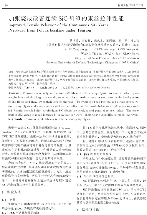
加张烧成改善连续SiC纤维的束丝拉伸性能Improved Tensile Behavior of the Continuous SiC YarnsPyrolyZed from Polycarbosilane under Tension楚增勇,冯春祥,宋永才,王应德,王军,肖加余(国防科技大学新型陶瓷纤维及其复合材料重点实验室,长沙410073DC U Zeng-yong,FENG Chun-iang,SONG Yong-cai,WANG Ying-de,WANG Jun,XIAO Jia-yu(Key Lab of New Ceramic Fibers S Composites,National University of Defense Technology,Changsha410073,China D摘要先驱体法制备连续SiC纤维在烧成过程中有明显的失重和收缩行为,导致纤维在弯曲处应力集中,从而影响其单丝强度和束丝拉伸性能本工作通过施加一定的张力研究加张烧成方式对连续SiC纤维束丝拉伸性能的影响结果表明,通过适当的加张,烧成后的纤维平直,丝间平行程度明显改善,束丝断裂负荷显著增加,可编织性明显加强关键词连续SiC纤维拉伸性能烧成中图分类号T 343.6文献标识码A文章编号1001-4381(2003D06-0036-02Abstract Preparation of polymer-derived SiC fibers involves a pyrolysis process,in which great weight loss and shrinkage are usually recorded.As a result,stress concentrates on the bend portion of the fibers and then lower their tensile strength.To avoid the bend portion and stress concentra-tion,a pyrolysis under tension,as well as their effect on the tensile behavior of SiC yarns was stud-ied.Results revealed that so-obtained SiC fibers are straight and parallel to each other.The crack load of SiC yarns is much increased,or in another word,their weave capability is much improved. Key words continuous SiC fibers tensile behavior pyrolysis先驱体法连续SiC纤维是由聚碳硅烷(Polycar-bosilane,PCS D先驱体经熔纺不熔化烧成而得与C D SiC纤维相比,先驱体法SiC纤维具有直径细,柔顺性好,可编性强的优点,因而其商品已以各种编织体的形式用作耐热材料和复合材料的增强体[1]但先驱丝在无机化的烧成过程中有明显的失重和收缩行为,会导致纤维在弯曲处应力集中,从而影响其单丝强度和束丝拉伸性能,进而影响其可编织性为防止纤维产生小弯,就必须施加一定的张力然而在烧成过程中,单丝强度和束丝承载能力是在显著变化的,具体加张制度文献报道较少,为此,通过理论推导与实验模索,研究了一套行之有效的加张体系[2,3]本研究则着重探讨上述加张烧成过程对连续SiC纤维的束丝拉伸性能的影响实验方法.原料先驱体PCS由本室提供,软化点200 210C,数均分子量1800,为脆性有机硅高聚物[4].2PCS不熔化纤维的制备将PCS置于多孔熔融纺丝机中,在高纯N2保护下,加热至纺丝温度,脱泡处理,于一定压力下经多孔喷丝组件挤出,牵伸成型为连续PCS原纤维[5]将上述原纤维移入预氧化炉中,边鼓风边加热,缓慢升至200C并保温2h,即得Si-反应程度80%,凝胶含量为100%的PCS不熔化纤维.3PCS纤维的加张烧成采用文献[2]中加张装置,通过外置的砝码调节张力大小,在高纯N2的保护下,于石英管式炉中由室温加热至1250C并保温30min,于炉中冷却至室温,便得到具有金属色泽的SiC陶瓷纤维.4SiC纤维拉伸性能测试SiC纤维的单丝强度在YG型强力仪上测得,跨距为25mm取30个数据的平均值作为最终结果SiC纤维束的拉伸曲线在CSC-1101型电子万能试样机上测得测试前纤维束没有上胶,只是用环氧树脂将纤维固定在跨距为25mm的纸框上由仪器配备的电脑采集数据绘制拉伸曲线2结果与讨论63材料工程!2003年6期2.l加张对SiC纤维单丝强度的影响根据PCS纤维热分解过程的研究[6]600C以前纤维还是有机的强度极低而600C到1000C是剧烈的热分解阶段强度变化较大可承载负荷也在大辐度提升;1000C时纤维已基本无机化纤维强度也达到较高值可承载较大负荷O所以本研究选择两段加张体系一段在1000C前一段在1000~1250C O 加张制度与加张对SiC纤维单丝强度的影响见表1O表l加张对SiC纤维抗拉强度的影响Table1Effect of firing tension on thetensile strength of SiC fibersTension/(c -yarn-1D200~1000C1000~1250CTensile strength/GPa55 1.70105 1.77155 1.822051.61(Wholly broken at200C D1510 1.80 1520 1.78 1530 1.85 1540 1.84 1550 1.8815601.84(Partially broken at1100C D由表1可见加张可以将纤维从无张力的1.70GPa提升到1.88GPa增加约10%O但前期加张和后期加张的效果大不一样强度的提高基本上是前期加张所贡献的O实际上PCS有机纤维在热效应的作用下有热膨胀行为塑性也增强在一定的张力作用下有所伸长(1%~2%D[2]O这些伸长虽不能显著地降低纤维的直径但对于去除小弯拉直纤维使纤维之间平行程度增加还是有较大贡献的O而纤维强度的增加也就是由于小弯去除以后局部应力集中现象得到了较好控制O但是有机纤维的强度太低不宜采用过高的张力( 20c /束D O1000C烧成后纤维强度可达到1.50GPa纤维承载能力明显加强但纤维强度是呈统计分布的张力大到一定程度纤维束内部较差的纤维开始断裂O为避免产生过高的断头率第二段的张力不应超过60c /束O第二段的加张对强度的提高仍有一定的贡献这是因为1000C的纤维还含有少量的在1250C烧成之前缓慢释放伴有少量失重与收缩[6]O如没有张力局部应力集中仍难以完全避免O研究表明高温下SiC纤维可以依靠粘流过程促使表面开口气孔封闭[7]加张显然可以更有效地促进这一过程封闭开口气孔减少表面缺陷提高强度O2.2加张对SiC纤维宏观形貌的影响加张烧成的SiC纤维束的宏观形貌示于图1 并与无张力烧成的纤维束进行了对比O图1无张力(a D与有张力(b D烧成的SiC纤维束宏观形貌Fig.1Macroscopic morphology of SiC fiber bundles preparedWithout tension(a D With tension(b D and a scale ruler(c D无张力条件下烧成的SiC纤维束较蓬松局部有小弯纤维与纤维之间相互交错毛丝现象比较严重O 反之加张后烧成的纤维束结合紧密纤维平直纤维与纤维之间平行程度明显加强纤维宏观规整性与光泽度也明显改善O如上所述这种宏观形貌的改善主要得益于第一段低温加张时纤维伸长而相互趋于靠近平行O同时第二段张力作用下表面开口气孔的减少对光泽度的提高也是有利的O2.3加张对SiC纤维束丝拉伸性能的影响有张力与无张力烧成的SiC纤维束的拉伸曲线如图2所示O由图2可知无张力烧成的单根纤维之间是部分交叉的松紧程度不一致这样在拉伸时较紧的纤维首先承载较松的纤维后承载且其拉应力肯定低于较紧的纤维O所以当拉伸到一定程度后部分较紧的纤维发生断裂而使载荷出现一个小的峰值随后承载的纤维数目减少最终的断裂负荷也就明显降低O 而对于加张条件下烧成的纤维束显微镜下呈相互平行状态所以当拉伸时所有的纤维就可能同时承载O虽然由于强度统计分布的原因拉伸过程中也会有纤维不断断裂但发生这种断裂的纤维是单个进行的而不可能有多根纤维同时断裂所以其拉伸曲线近似一条直线且其最大值也与理论推导值接近[3]O 比较两种条件下的拉伸过程显然可以发现加张烧成的纤维束丝拉伸性能大大改善其断裂负荷增加(下转第40页D73加张烧成改善连续SiC纤维的束丝拉伸性能的高温场合要求硅橡胶的最高使用温度达到300C以上该胶粘剂也满足了这一高度的要求表4粘接件经高温老化后的扯离强度Table4Adhesion strength of cohesivebody after high temperature agedCohesive body 6144silicone rubber 30CrMnSiA steel PS360silicone 30CrMnSiA steel~eat-agedconditiontem-peratureCTime/h20010020000100020002 00010001 00300100200003 0~~~UTest temperature20C200C2.17 1.391.82 1.041.74 1.061.8 0.981.880.832.77 1.172.70 1.322.22 1.302.2 1.102.30 1.401.10-0.66-3结论f e23和稀土氧化物共混物作耐热添加剂使胶粘剂的耐热性能显著提高可达3 0C乙烯基三特丁基过氧化硅烷与硅橡胶混合配成胶粘剂攻克了难粘材料硅橡胶的粘接技术难点显著提高胶粘剂的粘接强度乙烯基三特丁基过氧化硅烷金属氧化物与硅橡胶混合配成胶粘剂使粘接件在室温下的粘接扯离强度达2.MPa以上在300C下的粘接扯离强度达0.83*1.4 MPa参考文献[1]林尚安.高分子化学[M] 北京:科学出版社1982.773.[2]Shied J.Adhesives~andbook3rd Ed Stoneham MassachusettsButterworth1974.[3]E L wannick et al.Rubber Chem Technol1978 2:438-63.[4]苏正涛.天津大学博士学位论文1997.31- 0.收稿日期:2003-03-16作者简介:郑诗建(1969-)男工程师在职攻读硕士从事橡胶密封材料的研究联系地址:北京81信箱7分箱(10009 ).(上接第37页)了近一倍(从7.8N升到14N)同时毛丝现象减少柔顺性增强所以可编织性也明显加强图2无张力(a)与有张力(b)烧成的SiC纤维束的拉伸曲线f ig.2Load-elongation curves of SiC fiber bundleswithout tension(a)and with tension(b)3结论(1)PCS不熔化纤维烧成过程中适当加张可以给纤维有效赋形避免小弯减少局部应力集中提高所得SiC纤维的单丝强度(2)加张烧成可以明显改善纤维之间的平行程度从而使得其断裂负荷大大增加同时加张烧成后的束丝宏观规整性加强毛丝现象减少柔顺性增强可编织性也大大加强参考文献[1]楚增勇冯春祥宋永才等.先驱体转化法连续SiC纤维国内外研究与开发现状[J].无机材料学报2002 17:193-202.[2]Z Y Chu C X f eng Y C Song et al.Influence of firing tensionon the mechanical properties of polymer-derived SiC fibers[A].proceedings of ICCM-13[C].Beijing2001.[3]Z Y Chu C X f eng Y C Song et al.Tensile strength evalua-tion of a polymer-derived multifilament continuous SiC fiber[A].proceedings of ISM2E-YS[C].Changsha2001.[4]Z Y Chu et al.Enhanced irradiation cross-linking of polycarbosi-lane[J].J Mater Sci Lett1999 18:1793-179 .[ ]Z Y Chu Y D wang C X f eng et al.Effect of spinning tech-nigues on the mechanical properties of polymer-derived SiC fiber [J].Key Eng Mater2002 224-226: 6 1-6 6.[6]Y~asegawa M Limura S Yajima.Synthesis of continuous sili-con carbide fiber with high tensile strength and high Young/s modulus[J].J Mater Sci1980 1 :720-728.[7]J LipowitZ J A Rabe L K f revel R L Miller.J Mater Sci1990 2 :2118-2124.收稿日期:2002-01-17作者简介:楚增勇(1974-)男博士研究生主要从事陶瓷先驱体与高性能陶瓷纤维的研究联系地址:湖南长沙国防科技大学一院Cf C 重点实验室(410073).04材料工程/2003年6期加张烧成改善连续SiC纤维的束丝拉伸性能作者:楚增勇, 冯春祥, 宋永才, 王应德, 王军, 肖加余作者单位:国防科技大学新型陶瓷纤维及其复合材料重点实验室,长沙,410073刊名:材料工程英文刊名:JOURNAL OF MATERIALS ENGINEERING年,卷(期):2003(6)被引用次数:2次1.楚增勇;冯春祥;宋永才先驱体转化法连续SiC纤维国内外研究与开发现状[期刊论文]-无机材料学报 2002(02)2.Z Y Chu;C X Feng;Y C Song Influence of firing tension on the mechanical properties of polymer-derived SiC fibers 20013.Zeng-Yong Chu;Chun-Xiang Feng;Yong-Cai Song;Ying-De Wang;Jun Wang Tensile strength evaluation of a polymer-derived multifilament continuous SiC fiber[会议论文] 20014.Z Y Chu Enhanced irradiation cross-linking of polycarbosilane[外文期刊] 19995.Z Y Chu;Y D Wang;C X Feng Effect of spinning techniques on the mechanical properties of polymer-derived SiC fiber[外文期刊] 2002(224/226)6.Y HASEGAWA;M Limura;S Yajima Synthesis of continuous silicon carbide fiber with high tensile strength and high Young′s modulus[外文期刊] 19807.J Lipowitz;J A Rabe;L K Frevel;R L Miller查看详情 19901.郑春满.李效东.楚增勇.冯春祥聚碳硅烷纤维无机化过程中弯曲的形成及对SiC纤维性能的影响[期刊论文]-国防科技大学学报 2005(1)2.兰琳.夏文丽.陈剑铭.刘玲.丁绍楠.刘安华聚碳硅烷氮化热解法制备Si3 N4纤维[期刊论文]-功能材料 2013(20)引用本文格式:楚增勇.冯春祥.宋永才.王应德.王军.肖加余加张烧成改善连续SiC纤维的束丝拉伸性能[期刊论文] -材料工程 2003(6)。
Effect of Microstructural Factors on Tensile Properties of an ECAE-Processed AZ31 Magnesium Alloy
Effect of Microstructural Factors on Tensile Properties of an ECAE-Processed AZ31Magnesium Alloy *1Yu Yoshida *2,Lawrence Cisar *2,Shigeharu Kamado and Yo KojimaDepartment of Mechanical Engineering,Nagaoka University of Technology,Nagaoka 940-2188,JapanMg–3%Al–1%Zn (AZ31)alloy was subjected to ECAE (Equal Channel Angular Extrusion)processing under various processing conditions.Then tensile tests were carried out at room temperature to investigate the relationship between tensile properties and microstructural parameters that include grain size and the texture generated by ECAE processing.In 4-pass ECAE specimens processed at 523K,tensile ductility is improved as a result of easy basal slip during tensile test along the extrusion direction,because such specimens have textures in which the basal plane is inclined at 45 to the extrusion direction.On the other hand,in the specimens processed at 573K,0.2%proof stress is higher than those of specimens processed at lower temperatures,but elongation is smaller.This is because of difficult basal slip caused by the textures in which the basal plane is oriented parallel to the extrusion direction.However,8-pass specimens processed at 473K and subsequently annealed,which have similar textures but different grain sizes (d ),exhibit clear grain size dependencies of 0.2%proof stress ( 0:2)according to Hall-Petch relationship; 0:2¼30þ0:17d À1=2.Therefore,crystallographic orientation has a profound effect on the tensile properties of AZ31alloy,and grain size has a little effect.(Received October 23,2002;Accepted February 7,2003)Keywords:equal channel angular extrusion process,magnesium alloy,tensile properties,texture,grain size dependence1.IntroductionAlthough magnesium alloys are expected to be useful materials for minimizing global environmental problems,wider applications of the alloys have not been achieved due to their inferior cold workability.Generally,it has been said that the less cold workability of magnesium results from its limited slip system at room temperature.Recently,however,there are some instances 1–4)where the ductility is improved in grain-refined magnesium alloys even at room temperature.This suggests that the poor ductility of magnesium relates to microstructural conditions,and not necessarily to intrinsic nature of the material.There is a large number of reports 4–12)about the correla-tion between grain size and mechanical properties of magnesium alloys based on Hall-Petch relation.In magne-sium,the critical resolved shear stress (CRSS)for non-basal slip is about one hundred times as large as that for basal slip.13)This difference of the CRSS gives rise to anisotropy of mechanical properties resulting from the slip system.Consequently,when the mechanical properties of wrought magnesium alloys that have strong crystallographic texture in their structures are investigated,considering the crystal-lographic orientation in addition to the grain size is important.6,7)In cold rolled magnesium alloys,the basal plane is oriented parallel to the rolling direction,that is,the so-called basal texture is formed.14,15)The basal texture is also generated in hot rolled magnesium alloys.7,15,16)Furthermore,in extruded magnesium alloys,the texture in which the basal plane is oriented parallel to the extrusion direction is formed.6,12,16,17)If these materials were deformed along the working direction,the ductility is expected to be small because shear force does not operate on the basal plane due to small Schmid factor thatis nearly 0.Therefore,their workability will also be small when secondary working is carried out at room temperature using the rolled or extruded materials.In a previous study,18)ECAE processing 19,20)was applied to Mg–Al–Zn alloys as a method not only for grain refinement but also for texture control.As a result,a peculiar texture in which the basal plane is inclined at 45 to the extrusion direction was formed,and therefore,the ductility was improved significantly.However,the relationship between ECAE processing conditions and the formed microstructures including texture,as well as the effect of the microstructure on tensile properties of the ECAE-processed specimen have not been clarified yet.In the present study,extruded AZ31magnesium alloy was subjected to ECAE processing.Then the effect of ECAE processing conditions,such as the process temperature and repetitive number of ECAE process,on grain size and texture formation was examined.Subsequently,the ECAE-proces-sed specimens were subjected to tensile tests.Then the correlation between tensile properties and microstructural parameters,such as grain size and texture are investigated.Furthermore,the effect of microstuructural changes with annealing on tensile properties of ECAE-processed speci-mens is also investigated.2.Experimental ProcedureCommercial AZ31extruded rods with 19mm diameter were obtained for the investigations carried out in the present study.The chemical composition of the alloy is shown in Table 1.Figure 1shows a schematic illustration of the ECAETable 1Chemical composition of AZ31alloy used for present study (mass%).Alloy Al Zn Mn Fe Si Cu Ni Mg AZ313.260.920.430.0040.0010.0000.001bal.*1ThisPaper was Originally Published in the Journal of Japan Institute of Light Metals 52(2002)559–565.*2Graduate Student,Nagaoka University of Technology.Materials Transactions ,Vol.44,No.4(2003)pp.468to 475Special Issue on Platform Science and Technology for Advanced Magnesium Alloys,II #2003The Japan Institute of Light Metalsprocess used for the present study.During the ECAE processing,the specimen is inserted into the upper part of the die and pressed.Then the specimen is subjected to shear force at the intersecting point of two equal channels.The ECAE die used for the present study has two equal channels of15mm diameter.The intersecting angle between the two channels is90 and the angle of the outer arc at the intersection is60 .Using this ECAE die,an equivalent strain of94%can be introduced.21)The extruded bars were machined to cylindrical specimens with a diameter of15mm and a length of80mm for ECAE processing.Table2shows the ECAE processing conditions. The ECAE processing was carried out at473,523and573K, respectively,with constant extrusion rate of20mm/min.The processing was repeated2,4and8times with the specimens rotated at the angles shown in Table2around the specimens longitudinal axis.Furthermore,8-pass ECAE specimens processed at473K were subjected to isochronal annealing at 448–673K for1h and at673–773K for4h in order to investigate the correlation between grain size and tensile properties.Optical microscope observations of all specimens were performed,and the grain size was simultaneously evaluated by image processing analysis.Furthermore,in the annealed specimens,Vickers hardness test was carried out and the change in hardness with annealing was investigated.Tensile tests were carried out at room temperature under a strain rate of8:33Â10À4sÀ1.The ECAE-processed samples were machined to JIS14A tensile specimens having a gage dimension of4mm diameter and20mm length,with their central axes remaining the same as before ECAE processing. After tensile test,the microstructures near the fractured surfaces were observed using optical microscope.In order to analyze the textures generated by plastic working,(0002)polefigures were drawn by Schulz reflection method22)using X-ray diffractometer.The measurements were performed using CuK (wave length ¼0:15406nm) radiation at40kV and200mA with the sample tilt angle ranging from0–70 .3.Results and Discussion3.1Microstructures and tensile properties of as-ECAEspecimens3.1.1Microstructures of as-ECAE specimensFigure2shows microstructures of as-received specimen,2 and4-pass ECAE processed specimens(hereafter referred to as2-pass and4-pass specimens,respectively).The micro-structures of all ECAE specimens consist of many unde-formed equiaxed grains.This suggests that dynamic recrystallization occurs during ECAE processing.Average grain sizes increase with increasing processing temperature in both2and4-pass specimens.However,the average grain sizes decrease with increasing number of processing at each temperature.In the specimen processed at473K,although veryfine grains of about1m m are observed,somecoarse Fig.1Schematic illustration of ECAE process.Table2ECAE processing conditions.Number of processing2,48Specimen rotation(deg)2nd:1803rd:904th:18090Working temperature(K)473523573473Extrusion rate(mm/min)20Annealing condition—448–673K-1h673–773K-4hFig.2Microstructures of as-received and ECAE specimens processed at(a)473K,(b)523K and(c)573K.Grain sizes are indicated in thefigure. Tensile Properties of ECAE-Processed AZ31Magnesium Alloy469unrecrystallized grains still remain.This is because the low temperature processing makes both dynamic recrystallization and subsequent grain growth difficult.Furthermore,the homogeneity of the grain sizes is improved by repeating the processing.On the other hand,in the specimens processed at 523K and573K,the variation in grain sizes becomes small. This is as a result of increase in the volume fraction of recrystallized grains generated by dynamic recrystallization during ECAE processing and subsequent grain growth due to relatively high temperature processing.From the above results,it can be concluded that the processing temperature and the number of repetitive proces-sing have profound effect on the recrystallized grain size and homogeneity of the microstructure,respectively.Further-more,in high temperature processing,although the grain sizes are large,homogeneous microstructure can be obtained with a small number of processing.For the achievement of fine and homogeneous microstructure,a large number of processing at a relatively low temperature will be required.3.1.2Tensile propertiesFigure3shows stress-strain curves of the as-received specimen and as-ECAE specimens processed under various conditions.Both the tensile strength and the0.2%proof stress of the2-pass specimens increase with increasing processing temperature.The stress-strain curve of the573K-2-pass specimen is similar to that of the as-received specimen. However,the523K-2-pass specimen exhibits an elongation of25%,which is higher than that of the as-received specimen (19%),while the elongation of the473K-2-pass specimen is merely8%.This value of8%is much lower than that of the as-received specimen.On the other hand,the elongation of the4-pass specimens processed at473K and523K are improved significantly compared to that of the2-pass specimens processed at those paring 473K-4-pass specimen with523K-4-pass specimen,the tensile strength and0.2%proof stress are almost same. However,the elongation of the latter specimen is higher than that of the former specimen.Furthermore,the tensile proper-ties of573K-4-pass specimen are almost the same as those of the573K-2-pass specimen.However,the0.2%proof stress of the former is slightly lower than that of the latter.As described in section3.1.1,the grain size decreases with decreasing ECAE processing temperature.Generally,in discussing the strength of a material,Hall-Petch relation is often used.However,such grain size dependency of the0.2% proof stress could not be found from the present results. Therefore,it is inferred that the tensile properties,especially 0.2%proof stress,must have been influenced by the crystallographic texture due to strong anisotropy of the slip systems at room temperature.The relationship between tensile properties and textures will be discussed in details in section3.1.4.3.1.3Microstructures of tensile fractured specimens Figure4shows microstructures near the fractured surfaces of the tensile tested specimens.Some twins are observed in the coarse grains in the specimens processed at473K.The existence of twins indicates that the deformability of the coarse grains is lower than that of thefine grains.Conse-quently,the coarse grains may be responsible for the low elongation of these specimens.In fact,the elongation is enhanced in the473K-4-pass specimen that has less coarse grains than the473K-2-pass specimen.On the other hand, the microstructures of the specimens processed at523K are homogeneous without coarse grains.It is noted that the grains of523K-4-pass specimen that exhibits high elongation of 35%are elongated towards the tensile direction.This elongation of the grains suggests that dislocation slip operates actively in the grains and that contributes to the ductility of the specimen.Furthermore,some twins are observed in the523K-4-pass specimen,but the twins are uniformly distributed in the microstructure.This result indicates that the deformation is uniform in each grain. Thus,the uniform deformation of the grains may cause improvement of the ductility.A large number of twins are observed in the specimens processed at573K.In these specimens,it is considered that twinning also contributes to the whole deformation in addition to dislocation slip.This deformation mechanism is different from that of the speci-mens processed at523K because the grains of the specimens processed at573K remainequiaxed. Fig.3Stress-strain curves of2-pass(top)and4-pass(bottom)ECAEspecimens processed at various temperatures.470Y.Yoshida,L.Cisar,S.Kamado and Y.Kojima3.1.4TextureFigure 5shows (0002)pole figures of as-received and as-ECAE specimens.The measurements were carried out on the planes parallel to the extrusion direction.The basal plane of the as-received specimen is oriented parallel to the extrusion direction.This is the typical texture observed in extruded rods of magnesium alloys.6,12)In the 473K-2-pass specimen,the texture consists of high intensity basal planes inclined at 45 to the extrusion direction and lower intensity ones parallel to the extrusion direction.The intensity of the former decreases with increasing processing temperature,while that of the latter increases.In the 573K-2-pass specimen,the basal plane is only oriented parallel to the extrusion direction.The 473K and 523K-4-pass specimens have similar textures.In these specimens,the intensity of the basal planes parallel to the extrusion direction decreases compared to 2-pass specimens processed at same temperature.However,the intensity of the inclined basal planes increases.Furthermore,the intensity of the basal plane parallel to the extrusion direction of the 573K-4-pass specimen is higher than that of the 573K-2-pass specimen.Thus,repetitive ECAE processing makes the obtained texture strongly exhibit preferred orientation ac-cording to the processing temperatures.The textures generated by ECAE processing can be classified into two types according to the orientations of the basal plane.These orientations are represented schematically in Fig.6.At a moderately low temperature of about 473K,the basal plane is inclined at 45 to the extrusion direction along the shear plane during the ECAE processing.On the other hand,at a relatively high temperature of about 573K,the basal plane is oriented parallel to the extrusion direction.Furthermore,in both texture (a)and (b),two types of orientations that are misaligned at 30 around the c-axis can be expected according to a previous study.18)If the specimen having texture (a)is tensioned along the extrusion direction,easy basal slip would occur because maximum shear force occurs on the plane inclined at 45 to the tensile direction.As a result,both the tensile strength and 0.2%proof stress would be remarkably reduced.It is expected that the easy basal slip will also be related to the enhancement of the elongation.In fact,the elongation reaches an extraordinarily high value of 35%in the 523K-4-pass specimen that has ahomogeneousFig.4Microstructures near the fractured surfaces of ECAE specimens processed at (a)473K,(b)523K and (c)573K.Fig.5(0002)pole figures of as-received and ECAE specimens processed at (a)473K,(b)523K and (c)573K.Tensile Properties of ECAE-Processed AZ31Magnesium Alloy 471microstructure.However,it is difficult for the grains to be significantly elongated,as shown in Fig.4,by only basal slip because the independent slip modes of basal slip are only two.23)Therefore,in the specimens that exhibit high ductility like the 523K-4-pass specimen,cross-slip from basal plane to non-basal plane as established by Koike et al.24,25)might be in operation in addition to basal slip.On the other hand,in the specimens having texture (b)in which the basal plane is oriented parallel to the extrusion direction,the Schmid factors for basal slip is nearly 0when the specimens are tensioned along the extrusion direction.Therefore,almost no shear force operates on the basal plane.As a result,it would be difficult for basal slip to occur.Consequently,the tensile strength and 0.2%proof stress would increase simultaneously with decrease of the elongation compared to the specimens having texture (a).This tendency is similar to the as-received specimen.Furthermore,in the 523K-2-pass specimen that has mixed texture of (a)and (b),the 0.2%proof stress exhibits intermediate value between that of the specimens having textures (a)and (b).Thus,the tensile strength and 0.2%proof stress of all specimens,as well as the elongation of the specimens having homogeneous microstructures,correspond well to their crystallographic orientations.3.2Changes in microstructures and tensile properties with annealingThe 8-pass as-ECAE specimens were annealed in order to investigate the changes in microstructures and mechanical properties with annealing.3.2.1Changes in hardness and microstructuresFigure 7shows optical micrographs of the 8-pass as-ECAE and the annealed specimens,while the changes in Vickers hardness with annealing are shown in Fig.8.Fine and equiaxed grains are homogeneously generated in the microstructure of the 8-pass as-ECAE specimen.This is as a result of the multiple pass ECAE processing at 473K.The hardness decreases suddenly after annealing at 448K for 1h.The specimen annealed at 523K for 1h has fully softened,and the grains have coarsened up to average grain size of 4.3m m with homogeneous microstructure as shown in Fig.7.At this point,it is inferred that recrystallization driven by residual strain is complete.Therefore,the subsequent decrease of the hardness becomes gentle.Isochronal anneal-ing for 4h was carried out at higher temperatures in orderto Fig.6Schematic illustration of crystallographic orientations formed by ECAEprocessing.Fig.7Microstructures of (a)8-pass ECAE-processed specimen and specimens subsequently annealed at (b)523K-1h,(c)723K-4h and (d)773K-4h.Grain sizes are indicated in thefigure.Fig.8Change in hardness with isochronal annealing.472Y.Yoshida,L.Cisar,S.Kamado and Y.Kojimaobtain further coarse grain size and microstructures.The microstructures and the changes in hardness are also shown in Figs.7and 8,respectively.The grain size of 723K-4h annealed specimen is coarser than that of the 523K-1h annealed specimen but the microstructure remains homo-geneous.This result suggests that normal grain growth occurs up to relatively high temperatures in the investigated alloy.However,the grains of the 773K-4h annealed specimen coarsen up to average grain size of 25.5m m with a large reduction of hardness as a result of abnormal grain growth.3.2.2Tensile propertiesFigure 9shows the stress-strain curves of 8-pass as-ECAE and annealed specimens.Both the tensile strength and 0.2%proof stress of all specimens decrease with increasing annealing temperature.That is,the strength of the specimens exhibits grain size dependencies.The specimens exhibit almost the same elongation,except the 773K-4h annealed specimen,which is lower.According to Koike et al.,24)the cross-slip from basal to non-basal plane,as mentioned earlier,can be operative within the grain size range up to 10m m .Therefore,in the 773K-4h annealed specimen having extraordinary coarse grains due to abnormal grain growth,the elongation would decrease.3.2.3TextureFigure 10shows the (0002)pole figures of the 8-pass as-ECAE and annealed specimens.Annealing reduces the intensities of preferred orientation.This tendency is similar to that of annealed AZ31hot-rolled samples.15)In the pole figure of 773K-4h annealed specimen,some high peaks,which may correspond to extraordinarily coarse grains,are observed inclined at about 10 to the extrusion direction.However,significant textural changes are not observed between the annealed specimens.3.2.4Grain size dependencyAs expressed in section 3.1.2,the yield stress ( y )of polycrystalline metals usually depends on the grain size,according to the Hall-Petch relation as described below,y ¼ 0þkd À1=2ð1Þwhere 0is yield strength of single crystalline material,k is material constant,and d is grain size.Armstrong 5)proposed a ‘‘pile-up’’model in which 0and k of hcp materials relate to both CRSS for the easiest slip system and the CRSS for the slip system required to maintain the continuity of crystals at the grain boundaries when dislocations are accumulated at the grain boundaries.In addition,Rao et al.7)supposed that 0and k relate to CRSS for basal a slip and for prismatic a slip,respectively,and concluded that their orientation factors influence 0and k .Thus,in magnesium alloys,the crystal-lographic orientation is extremely important during investi-gation of the grain size dependency of 0.2%proof stress.However,the grain size dependency dose not exist in the specimens having different textures as discussed in section 3.1.Figure 11shows the correlation between the grain size and the 0.2%proof stress of both the 8-pass as-ECAE and annealed specimens.In the annealed specimens having similar textures,the clear grain size dependency of 0.2%proof stress is exhibited according to Hall-Petch relation.Then 0is 30MPa and k is 0.17MPa/m À1=2.Koike et al.26)have shown that 0is approximately 60MPa when the grain size is the only effective factor.That is,when the effects of precipitates and/or plastic strain are negligible.However,the 0value obtained in the present study is half of the value proposed by Koike et al.It is expected that the basal a slipofFig.9Stress-strain curves of 8-pass as-ECAE and annealedspecimens.Fig.10(0002)pole figures of (a)8-pass ECAE-processed specimen and specimens subsequently annealed at (b)523K-1h,(c)723K-4h and (d)773K-4h.Tensile Properties of ECAE-Processed AZ31Magnesium Alloy 473the annealed specimens operates easily because most of the basal planes are inclined to the tensile axis.Thus,the easy basal slip brings about the reduction of the 0value.On the other hand,the k value of 0.17MPa/m À1=2corresponds to that obtained by Koike et al.25)Wilson 6)and Rao et al.7)reported that the k value depends on crystallographic orientation and decreases when magnesium alloys have strong preferred orientation in their texture.Thus,further researches are required to clarify the correlation between texture and grain size dependencies of 0.2%proof stress.The 0.2%proof stress of the 8-pass as-ECAE specimen is lower than the value expected from extrapolating the data for the annealed specimens.In this specimen,basal slip occurs easily because the intensity of the basal planes inclined to the tensile direction is higher than that of the annealed speci-mens.Therefore,cross-slip to non-basal plane may occur easily.This mechanism weakens the ability to obstruct dislocation motion.As a result,the grain size dependency might be reduced.Furthermore,Mabuchi et al.12)reported that the 0.2%proof stress of ECAE processed AZ91alloy having average grain size of 0.5m m is lower than the value obtained from Hall-Petch relation using other specimens.The specimen of the ECAE processed AZ91alloy contains many low-angle grain boundaries due to low processing tempera-ture of 448K.The authors concluded that absorption of dislocations at the low-angle grain boundaries causes the reduction of the 0.2%proof stress.It is also deduced that the above mechanism reduces the 0.2%proof stress of the present 8-pass as-ECAE specimen because low-angle grain boundaries might be formed as a result of 8-pass ECAE processing at a relatively low temperature of 473K.As mentioned earlier,if the grain size dependency of tensile properties of magnesium alloys having strong crystal anisotropy is discussed,the effect of crystallographic orientation should be considered.In addition,other micro-structural factors,for instance,dislocation density,amount of precipitates,grain boundary characteristics and so on,should also be considered.In the present study,the textures of the annealed specimens that exhibit clear grain size dependency are similar.Furthermore,it is inferred that the effect of dislocation density and the grain boundary characteristics onthe 0.2%proof stress is small because the microstructures of the specimens are fully recrystallized.Consequently,it can be concluded the 0.2%proof stress of the annealed specimens depend essentially on grain size.4.ConclusionsThe correlation between ECAE processing conditions,microstructures including texture and tensile properties have been investigated in order to reveal the effect of the microstructural parameters on the strength and ductility of AZ31magnesium alloy.The results are summarized as follows:(1)The grain sizes of ECAE-processed specimens decreasewith decreasing processing temperature.However,the microstructures are heterogeneous in the case of a small number of repetitive processing.A large number of repetitive processing at a low temperature is required to obtain fine and homogeneous grains.(2)The tensile strength and 0.2%proof stress of as-ECAEprocessed specimens are largely influenced by crystal-lographic orientation rather than grain size.In 523K-4-pass specimen,the 0.2%proof stress is reduced but elongation is significantly enhanced compared to those of as-received sample.This is because the specimen has a texture in which the basal plane is inclined at 45 to the tensile direction with a homogeneous microstruc-ture.On the other hand,in the 4-pass specimen processed at 573K,the 0.2%proof stress is higher and the elongation is lower because the basal plane is oriented parallel to the tensile direction.(3)Intensified degrees of texture of 8-pass ECAE-proces-sed specimens are weakened by annealing.The 0.2%proof stress of the annealed specimens decreases with increasing grain sizes,exhibiting clear grain size dependency according to Hall-Petch relation,that is, 0:2¼30þ0:17d À1=2.AcknowledgementsThe present study is supported by Grant-in-Aids for Scientific Research (A)(No.11305049)and the Priority Area (B)‘‘Platform Science and Technology for Advanced Magnesium Alloys (No.11225101)’’from the Ministry of Education,Culture,Sports,Science and Technology of Japan.REFERENCES1)T.Mukai,T.Mohri,M.Mabuchi,M.Nakamura,K.Ishikawa and K.Higashi:Scr.Mater.39(1998)1249–1253.2)K.Kubota,M,Mabuchi and K.Higashi:J.Mater.Sci.34(1999)2255–2262.3)T.Mukai,M.Yamanoi and K.Higashi:Mater.Sci.Forum 350–351(2000)97–102.4) A.Yamashita,Z.Horita and ngdon:Mater.Sci.Eng.A300(2001)142–147.5)R.W.Armstrong:Acta Metall.16(1968)347–355.6) D.V.Wilson:J.Inst.Metals 98(1970)133–143.7)G.Sambasiva Rao and Y.V.R.K.Prasad:Metall.Trans.A 13A (1982)2219–2226.8)T.Mohri,T.Nishiwaki,T.Kinoshita,H.Iwasaki,M.Mabuchi,M.Fig.11Grain size dependencies of 0.2%proof stress of 8-pass ECAE-processed and annealed specimens.474Y.Yoshida,L.Cisar,S.Kamado and Y.KojimaNakamura,T.Asahina,T.Aizawa and K.Higashi:Mater.Trans.,JIM 41(2000)1154–1156.9)M.Mabuchi and K.Higashi:Acta Mater.44(1996)4611–4618.10)Y.Chino,M.Mabuchi,K.Shimojima,Y.Yamada,C.Wen,K.Miwa,M.Nakamura,T.Asahina,K.Higashi and T.Aizawa:Mater.Trans.42 (2001)414–417.11)T.Mukai,M.Yamanoi,H.Watanabe,K.Ishikawa and K.Higashi:Mater.Trans.42(2001)1177–1181.12)M.Mabuchi,Y.Chino,H.Iwasaki,T.Aizawa and K.Higashi:Mater.Trans.42(2001)1182–1189.13)H.Yoshinaga and R.Horiuchi:Trans.JIM4(1963)1–8.14)I.Gokyu:J.JSME67(1964)488–493.15)K.Ohtoshi and M.Katsuta:J.JILM51(2001)534–538.16)J.Kaneko,M.Sugamata,M.Numa,Y.Nishikawa and H.Takada:J.Japan Inst.Metals64(2000)141–147.17)M.T.Pe´rez-Prado and O.A.Ruano:Scr.Mater.46(2002)149–155.18)Y.Yoshida,H.Yamada,K.Kamado and Y.Kojima:J.JILM51(2001)556–562.19)V.M.Segal:Mater.Sci.Eng.A197(1995)157–164.20)V.M.Segal:Mater.Sci.Eng.A271(1999)322–333.21)Y.Iwahashi,J.Wang,Z.Horita,M.Nemoto and ngdon:Scr.Mater.35(1996)143–146.22)L.G.Schulz:J.Appl.Phys.20(1949)1030–1033.23)M.H.Yoo:Metall.Trans.A12A(1981)409–418.24)J.Koike,T.Kobayashi,T.Mukai,H.Watanabe,M.Suzuki,K.Maruyama and K.Higashi:Acta Mater.in press.25)K.Kobayashi,J.Koike,T.Mukai,M.Suzuki,K.Higashi and K.Maruyama:Collected Abstracts of the2002Spring Meeting of the Japan Inst.Metals(2002)p.88.26)J.Koike and K.Kobayashi:Proceedings of a subcommittee symposiumof the Japan Inst.Metals‘‘Fundamentals of magnesium and industrial applications’’,(The Japan Inst.Metals,2001)pp.1–3.Tensile Properties of ECAE-Processed AZ31Magnesium Alloy475。
霍夫梅斯特效应 超分子水凝胶的机械强度
霍夫梅斯特效应超分子水凝胶的机械强度下载提示:该文档是本店铺精心编制而成的,希望大家下载后,能够帮助大家解决实际问题。
文档下载后可定制修改,请根据实际需要进行调整和使用,谢谢!本店铺为大家提供各种类型的实用资料,如教育随笔、日记赏析、句子摘抄、古诗大全、经典美文、话题作文、工作总结、词语解析、文案摘录、其他资料等等,想了解不同资料格式和写法,敬请关注!Download tips: This document is carefully compiled by this editor. I hope that after you download it, it can help you solve practical problems. The document can be customized and modified after downloading, please adjust and use it according to actual needs, thank you! In addition, this shop provides you with various types of practical materials, such as educational essays, diary appreciation, sentence excerpts, ancient poems, classic articles, topic composition, work summary, word parsing, copy excerpts, other materials and so on, want to know different data formats and writing methods, please pay attention!霍夫梅斯特效应是一种基于超分子化学的现象,它在许多领域中展现出重要的应用价值。
莫扎特效应 英语作文

莫扎特效应英语作文The Mozart Effect: Unlocking the Potential of the Human MindThe human mind is a remarkable and complex entity, capable of feats that continue to astound and captivate us. One of the most intriguing phenomena associated with the workings of the mind is the so-called "Mozart Effect." This concept refers to the idea that exposure to the classical music of the renowned composer Wolfgang Amadeus Mozart can have a positive impact on various cognitive abilities, particularly in the realm of spatial-temporal reasoning.The origins of the Mozart Effect can be traced back to a 1993 study conducted by researchers at the University of California, Irvine. In this study, a group of college students were asked to complete a series of spatial reasoning tasks before and after listening to a Mozart sonata. The results were quite remarkable – the students demonstrated a significant improvement in their performance on the spatial tasks after the musical exposure, leading the researchers to conclude that listening to Mozart's music had a measurable and immediate impact on certain cognitive functions.The implications of this finding were far-reaching, and the Mozart Effect quickly captured the public's imagination. The idea that a simple and enjoyable activity like listening to classical music could enhance one's intellectual abilities was both intriguing and empowering. Parents, educators, and policymakers alike began to explore the potential applications of this phenomenon, leading to a surge of interest and research in the field.One of the key aspects of the Mozart Effect that has captured the attention of the scientific community is its potential to shed light on the complex relationship between music and the brain. Numerous studies have since explored the neurological underpinnings of this effect, utilizing advanced imaging techniques to examine the brain's response to different types of music.These investigations have revealed that exposure to Mozart's music appears to activate specific regions of the brain associated with spatial-temporal reasoning, working memory, and other cognitive processes. The music's intricate and harmonious structure seems to stimulate the brain in a way that enhances its ability to process and manipulate spatial information, which is crucial for tasks like solving mathematical problems, understanding complex diagrams, and even performing certain types of surgery.Moreover, the Mozart Effect has been observed not only in adults but also in children and infants, suggesting that the cognitive benefits of listening to this music may begin at a very early age. This has led to the widespread adoption of "Mozart music therapy" in educational and early childhood settings, with the hope of providing children with a cognitive boost that can have lasting positive impacts on their academic and intellectual development.However, it is important to note that the Mozart Effect is not a universal panacea for cognitive enhancement. While numerous studies have corroborated the existence of this phenomenon, the extent and durability of its effects have been the subject of ongoing debate and research. Some studies have failed to replicate the original findings, leading some experts to question the reliability and generalizability of the Mozart Effect.Additionally, there is an ongoing discussion about the specific mechanisms by which the Mozart Effect operates. While the initial research suggested that the music itself was the primary driver of the cognitive improvements, more recent studies have raised the possibility that other factors, such as mood, arousal, or the specific task being performed, may also play a role in determining the extent and nature of the observed effects.Despite these caveats, the Mozart Effect remains a fascinating andintriguing area of scientific inquiry. Researchers continue to explore the potential applications of this phenomenon, investigating its implications for education, cognitive rehabilitation, and even the treatment of certain neurological and psychiatric conditions.For example, some studies have suggested that exposure to Mozart's music may have the potential to improve the cognitive function of individuals with Alzheimer's disease or other forms of dementia, potentially providing a non-pharmacological approach to cognitive enhancement and potentially delaying the onset of cognitive decline.Moreover, the Mozart Effect has inspired a broader exploration of the relationship between music and the brain, leading to a greater understanding of the ways in which different types of music can influence various cognitive and emotional processes. This research has significant implications for the fields of music therapy, neuroscience, and cognitive psychology, as it sheds light on the intricate and dynamic interplay between the auditory system, the brain, and the mind.In conclusion, the Mozart Effect remains a fascinating and multifaceted phenomenon that continues to captivate the scientific community and the public at large. While the precise mechanisms underlying this effect are still the subject of ongoing research, the available evidence suggests that exposure to the music of WolfgangAmadeus Mozart may indeed have the power to unlock the potential of the human mind, enhancing cognitive abilities and potentially providing a valuable tool for cognitive enhancement and rehabilitation. As we continue to explore the frontiers of the human mind, the Mozart Effect stands as a testament to the remarkable complexity and adaptability of the brain, and the transformative power of art and music.。
组织形貌对TC4钛合金棒材性能的影响
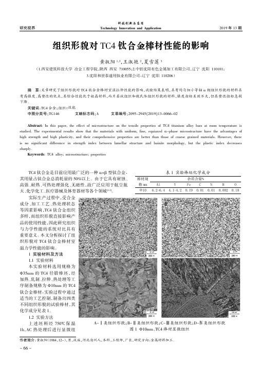
2019年13期研究视界科技创新与应用Technology Innovation and ApplicationA-Ⅰ类组织形貌;B-Ⅱ类组织形貌;C-Ⅲ类组织形貌;D-Ⅳ类组织形貌图1Ф10mm 、TC4棒材显微组织组织形貌对TC4钛合金棒材性能的影响黄淑阳1,3,王淑艳2,夏雪莲3(1.西安建筑科技大学冶金工程学院,陕西西安710055;2.中铝沈阳有色金属加工有限公司,辽宁沈阳110101;3.沈阳和世泰通用钛业有限公司,辽宁沈阳110206)TC4钛合金是目前应用最广泛的一种α+β型钛合金,其用量占钛合金总消耗量的50%以上。
由于它具有耐蚀、高强、耐热、可热处理强化、无磁性,故广泛应用于航空航天、化学化工、医疗器械及体育器材等各个领域[1-2]。
实际生产过程中,受合金成分、加工工艺、热处理状态等因素影响,TC4钛合金组织多样,而组织形貌直接影响产品的使用性能,因此研究组织与力学性能的系统对比具有重要意义。
本文分析探讨了组织形貌对TC4钛合金棒材室温力学性能的影响。
1实验材料及方法1.1实验材料本实验材料选用规格为Ф35mm 的TC4径锻棒坯,经加热、轧制、拉伸、热处理等工序制备规格为Ф10mm 的TC4钛合金棒材,实验过程中通过适当的工艺控制,制备出四类不同组织形貌的试验棒材,其化学成分见表1。
1.2实验方法上述坯料经750℃保温1h ,AC 热处理后进行显微组摘要:文章研究了组织形貌对TC4钛合金棒材室温拉伸性能的影响,试验结果表明,具有均匀细小等轴α相组织形貌的材料具有高强度、高塑性的优点,其综合性能优于粗晶材料,而片层状组织和魏氏体组织形貌的材料,强度指标差别不大,但其塑性指标急剧下降。
关键词:TC4合金;组织;性能中图分类号:TG146文献标志码:A文章编号:2095-2945(2019)13-0066-02Abstract :In this paper,the effect of microstructure on the tensile properties of TC4titanium alloy bars at room temperature isstudied.The experimental results show that the materials with uniform,fine,equiaxed α-phase microstructure have the advantages ofhigh strength and high plasticity,and their comprehensive properties are better than those of coarse grained materials.However,there is no significant difference in strength index between lamellar structure and bainite morphology,but the plastic index decreases sharply.Keywords :TC4alloy;microstructure;properties作者简介:黄淑阳(1984,12-),男,汉族,河北沧州人,本科,工程师,厂长,研究方向:金属材料加工。
Ti对大线能量焊接焊缝组织和性能的影响

Ti对大线能量焊接焊缝组织和性能的影响阿荣1,潘川1,赵琳2,田志凌3(1.安泰科技股份有限公司焊接材料分公司,北京100081;2.新冶高科技集团有限公司,北京100081;3.中国钢研科技集团有限公司,北京100081)摘要:对不同Ti含量的气电立焊焊缝组织及力学性能进行了对比研究。
结果表明,Ti的质量分数在0.028%~0.038%范围内时,焊缝中获得大量细小的针状铁素体,焊缝组织及低温韧性得以明显改善。
当Ti过量时,焊缝中的针状铁素体减少,组织以贝氏体为主,低温韧性相应下降。
焊缝组织中观察到块状和条状的M-A组元,随着焊缝Ti含量增加,其总量增加。
焊缝夹杂物多为以氧化物为核心,外层包裹着MnS的复合夹杂物,并随夹杂物Ti含量的增加,由Mn-Si-Al-O型向Ti-Mn-Al-O型转变,有利于促进针状铁素体形成。
而当焊缝中Ti过量时,主要夹杂物又转变为对针状铁素体形核无效的Ti-Al-O型,促进了贝氏体转变。
关键词:大线能量焊接;Ti;针状铁素体;M-A组元;焊缝组织;力学性能低合金高强钢焊缝力学性能主要受焊缝组织、焊缝金属化学成分及焊接热输入的影响。
一般,低合金高强钢焊缝组织主要以马氏体、贝氏体和铁素体为主。
为了获得较高的综合力学性能,焊缝中形成大量的针状铁素体是非常必要的。
针状铁素体转变温度为650~500℃,属中温转变产物。
典型的针状铁素体组织紧密,板条间角度通常大于15°,为大角度晶界,且针状铁素体晶内存在大量高密度位错(其密度为108~1010cm-2),因此在变形过程中不利于微裂纹扩展,宏观上表现出良好的断裂韧性及低温韧性[1-7]。
针状铁素体通常以那些尺寸为0.3~2.0μm,弥散分布的非金属夹杂物为形核质点,并与奥氏体母相之间保持一定的位相关系(K-S,N-W)生长。
对于特定条件的夹杂物是如何促进针状铁素体以及晶内铁素体形核长大的原因目前也有了部分一致的观点[8-13],其原理主要可以通过晶格匹配理论、界面能变化、应力应变场强变化及化学成分变化引起的化学驱动力提高等几个方面解释。
热处理对高强度铝合金微观组织和力学性能的影响
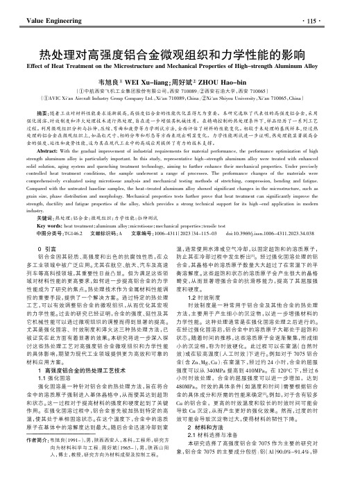
Value Engineering0引言铝合金因其轻质、高强度和出色的抗腐蚀性质,在众多工业领域中被广泛应用。
尤其在航空、航天、汽车及高速列车等高科技领域,其重要性日益凸显。
但为满足这些领域对材料性能的更高要求,如何进一步提高铝合金的力学性能成为了研究的焦点。
热处理技术作为金属材料性能调控的重要手段,提供了一个解决方案。
通过特定的热处理工艺,可以有效调整铝合金的微观组织,从而优化其宏观的力学性能。
过去的研究已经证明,合金的强度、延性及其它机械性能可以通过微观组织的调整而得到显著的提高。
尤其是强化固溶、时效制度和淬火这三种热处理方法,已被证实在此方面有着显著的效果。
本研究将进一步深入探讨这些热处理工艺对高强度铝合金微观组织和力学性能的具体影响,期望为现代工业领域提供更为高效和可靠的材料应用方案。
1高强度铝合金的热处理工艺技术1.1强化固溶强化固溶是一种针对铝合金的热处理方法,旨在将合金中的溶质原子强制进入基体晶格中,从而使其达到超饱和状态。
这一过程对于提高材料的强度和硬度起到了关键作用。
在强化固溶过程中,铝合金首先被加热到特定的高温,使其处于单相固溶状态。
在这个温度下,合金中的溶质原子在基体中的溶解度达到最大。
随后合金迅速冷却到室温,通常使用水淬或空气冷却,以固定超饱和的溶质原子,防止其在冷却过程中发生析出[1]。
经过强化固溶处理的铝合金,其晶格中的溶质原子数量大大超过了在常温下的平衡溶解度。
这些超饱和状态的溶质原子会产生很大的晶格畸变,从而显著增强合金的抗滑移能力,提高了其屈服强度和硬度。
1.2时效制度时效制度是一种常用于铝合金及其他合金的热处理方法,主要用于产生细小的沉淀物,以进一步增强材料的力学性能。
这种处理通常是在强化固溶处理之后进行的。
在经过强化固溶后,铝合金中的溶质原子大都处于超饱和状态。
随着时间的推移,这些溶质原子会逐渐聚集,形成细小的沉淀相,称为时效硬化。
此过程可以在室温(自然时效)或在较高温度(人工时效)下进行。
X80_管线钢中微观组织非均匀性对残余应力影响的实验研究
精 密 成 形 工 程第15卷 第8期106 JOURNAL OF NETSHAPE FORMING ENGINEERING2023年8月收稿日期:2023-05-11 Received :2023-05-11基金项目:天津市自然科学基金(19JCQNJC03700);国家自然科学基金(11502166);2022年天津市研究生科研创新项目(2022SKYZ163)Fund :The Natural Science Foundation of Tianjin(19JCQNJC03700); the National Natural Science Foundation of China (11502166); the Postgraduate Scientific Research Innovation Project of Tianjin (2022SKYZ163) 作者简介:任春华(1989—),男,博士,讲师,主要研究方向为实验固体力学。
Biography :REN Chun-hua(1989-), Male, Doctor, Lecturer, Research focus: experimental solid mechanics.引文格式:任春华, 周治顺, 计宏伟, 等. X80管线钢中微观组织非均匀性对残余应力影响的实验研究[J]. 精密成形工程, 2023, 15(8): 106-112.REN Chun-hua, ZHOU Zhi-shun, JI Hong-wei, et al. Experimental Study on the Effect of Microstructure Inhomogeneity on Re-X80管线钢中微观组织非均匀性对残余应力影响的实验研究任春华1,周治顺1,计宏伟1,朱雨逸2(1.天津商业大学 机械工程学院,天津 300134; 2.西交利物浦大学 智造生态学院,江苏 苏州 215028)摘要:目的 从微纳尺度研究X80管线钢微观组织的不均匀性对残余应力分布及释放过程的影响。
发用产品强韧功效评价方法
发用产品强韧功效评价方法English:The evaluation of the toughening efficacy of a product can be conducted through various methods. One common method is the tensile testing, which measures the force required to pull the product apart. This test can provide valuable information on the product's strength and toughness. Another method is the impact testing, which measures the product's ability to absorb energy under a sudden impact. This test can simulate real-life scenarios and provide insights into the product's resilience. Additionally, fracture toughness testing can also be employed to evaluate the product's resistance to crack propagation. This test can assess the product's ability to withstand sudden or repeated stresses. Furthermore, microscopic analysis can be used to examine the microstructure of the product, providing information on its internal toughness and resistance to deformation. It is important to consider a combination of these methods to comprehensively evaluate the toughening efficacy of a product.中文翻译:产品强韧功效的评价可以通过各种方法进行。
(TiB+TiC)Ti复合材料高温变形行为及组织性能研究材料加工工程专业毕业论文
(TiB+TiC)Ti复合材料高温变形行为及组织性能研究材料加工工程专业毕业论文摘要摘要原位自生钛基复合材料具有低密度、高比强度和比模量、优异的疲劳和蠕变性能,有望在航空航天、先进武器系统及汽车制造等领域获得广泛应用。
然而,钛基复合材料室温塑性差,高温变形抗力大,限制了其大规模的工程化应用。
本文采用真空感应熔炼技术制备了不同(TiC+TiB)含量的钛基复合材料,基体合金成分为Ti-6Al-2.5Sn-4Zr-0.7Mo-0.3Si。
研究了增强相含量对铸态复合材料显微组织和力学性能的影响;阐明了(TiB+TiC)/Ti 复合材料的热压缩变形行为及组织演变规律;探讨了热加工过程中的组织性能对应关系;开展了钛基复合材料板材的超塑性研究并揭示了其超塑性变形机理和失效机制。
凝固析出的T iB 和T iC 相易于偏聚于原始β晶界处,TiB 相主要呈晶须状,而TiC 则为近等轴状,二者均与基体界面结合良好。
TiB 和TiC 的引入细化了原始β晶粒和α片层,改变了α相的集束特征,并且使得α片层的取向更加随机。
β晶粒的细化机制为C 与B 在先析出的β-Ti 界面前沿富集引起成分过冷及抑制已析出的β-Ti 生长。
β晶粒的细化增多了β晶界,α相的形核位置增加,并且生长空间缩小,二者导致α片层发生细化。
TiB 和TiC 的存在显著提高了铸态(TiB+TiC)/Ti 复合材料的室温及高温强度。
室温下,相比于基体合金,增强相体积分数分别为 2.5%、5%、7.5%的复合材料的屈服强度分别提高了16.2%、20.2%、28.3%。
室温屈服强度的提高主要是因为基体组织的细化。
高温下,随测试温度升高,复合材料相对于基体合金的抗拉强度增幅呈先增加后降低趋势,在650℃时达到峰值。
650℃以下复合材料强度提高主要归因于组织细化,增强相承载强化以及 C 的固溶强化,而700℃以上的原因是增强相承载强化和C 的固溶强化。
采用热物理模拟方法,研究了5vol.%(TiB+TiC)/Ti 复合材料的热压缩变形行为,揭示了流变应力与变形温度和应变速率之间的关系,峰值应力和流变应力均随温度的升高和应变速率的减小而降低,且峰值应力σp 与(1000/T)、ln 之间都满足线性关系。
- 1、下载文档前请自行甄别文档内容的完整性,平台不提供额外的编辑、内容补充、找答案等附加服务。
- 2、"仅部分预览"的文档,不可在线预览部分如存在完整性等问题,可反馈申请退款(可完整预览的文档不适用该条件!)。
- 3、如文档侵犯您的权益,请联系客服反馈,我们会尽快为您处理(人工客服工作时间:9:00-18:30)。
Effect of tensile stress on microstructure evolution ofAl-Cu-Mg-Ag alloysZHOU Jie(周杰), LIU Zhi-yi(刘志义), LI Yun-tao(李云涛),LIU Yan-bin(刘延斌), XIA Qing-kun(夏卿坤), DUAN Shui-liang(段水亮)School of Materials Science and Engineering, Central South University, Changsha 410083, ChinaReceived 15 July 2007; accepted 10 September 2007Abstract: The effect of tensile stress on thermal microstructure evolution of Ω phase in an Al-Cu-Mg-Ag alloy with high Cu/Mg ratio and higher Ag content was investigated by transmission electron microcopy (TEM) .The samples were aged at 200 for 1℃ h (T6 condition), then thermal exposed at 250 for 100℃ h with and without a tensile stress (130 MPa), respectively. The results indicate that Ω precipitates uniformly disperse in the matrix as a major precipitate after artificially aging at 200 for 1℃ h (T6 condition). Exposed at 250 for 100℃ h without stress, Ω precipitates dissolve dramatically. Whereas, during stress exposure they coarsen unexpectedly rather than dissolve into matrix. It can be deduced that the stress retards the redissolution of Ω phase.Key words: Al-Cu-Mg-Ag alloy; Ω phase; thermal exposure; tensile stress1 IntroductionAl-Cu alloy has been widely used for structural materials because of their good age hardening characterizations and high temperature creep resistance with the precipitation of GP zones and θ′ plates on {001}Al planes. Additional trace elements of Mg and Ag have been found to induce the finely dispersed Ωprecipitate on {111}Al planes, replacing the conventional GP zones and θ′ plates on {001}Al planes[1]. The effect of the trace elements on Ω precipitation has been shown by atom probe field ion microcopy (APFIM) study[2] as Mg-Ag clusters formed at the beginning of aging, then Cu atoms aggregated into the clusters to form Ω nuclei on {111}Al planes. Ω precipitates appear to maintain coherency along the {111}Al planes at temperatures up to 200 , which is facilitated by segregation of Mg and Ag ℃atoms to the precipitate-matrix interface during growth of Ω (Fig.1)[1, 3].Considering strain energy, SUH et al have pointed out that the incorporation of Mg and Ag decreases the strain energy for the nucleation of Ω on {111}Al plane [4, 5]. Some research conclusions[6−11] showed that precipitation process could be modified dramatically on coupled elastically stress with temperature during aging (namely, stress aging), which helped to modify and control the species, quantity, shape, size, distribution and orientation of precipitates, and finally, to improve the mechanical properties of materials. Stress aging technology has been utilized in some aluminum alloys for a few years[7−12]. Since the Ω precipitate exhibits basically the stoichiometric composition ratio of Al2Cu compound and consequently changes into the stable θphase, the evolution of Ω and θ′ precipitates should be closely related with the mutual constituent Cu atoms in GP zones, θ′ and Ω. The stress effect on GP zones has been examined by ETO et al[13]. The preferential nucleation of Ω and θ′ plates under external stress has been reported[14, 15], nevertheless, stress effect on the thermal microstructure evolution of Ω phase has been uncertain.In this work, stress exposure is performed to investigate the microstructure evolution of Ω phase in an Al-Cu-Mg-Ag alloy after peak-aging treatment. The relative density change between Ω and θ′ plates depends on the respective stress sensitivities of Ω and θ′ plates. The thermal microstructure evolution of Ω and θ′ plates is qualitatively investigated by TEM observations. The exposure methods (the combination of the stress andFoundation item: Project(2005CB623705-04) supported by the National Basic Research Program of China Corresponding author: LIU Zhi-yi; Tel: +86-731-8836011; E-mail: liuzhiyi@ZHOU Jie, et al/Trans. Nonferrous Met. Soc. China 17(2007) s323Fig.1 3DAP elemental mapping of {111} plates in Al-Cu-Mg-Ag alloy and Mg-Ag co-clusters around Ω platesstress-free exposure after peak-aging condition, respectively at elevated temperature) are performed to study the effect of the stress on the microstructure evolution of Ω phase in an Al-Cu-Mg-Ag alloy with high Cu/Mg ratio and higher Ag content.2 ExperimentalThe nominal chemical composition of the alloy was Al-6.5Cu-0.4Mg-1.0Ag (mass fraction, %). Samples were solution treated at 515 for 6 h and then quenched℃into cold water rapidly. The quenched samples should be put into furnace as quickly as possible in order to prevent from natural aging. All the samples were aged at 200 ℃for 1 h (T6 condition), then exposed at 250 for 100℃ h. This treatment compared with exposure at 250 for 100℃h concurrently under a tensile stress of 130 MPa, the external stress applied on the samples was perpendicular to the rolling direction. Thin foil specimens for TEM (transmission electron microcopy) were prepared in a twin jet electron-polisher using a solution of 30% nitric acid and 70% methanol (volume fraction) at about −25 .℃ TEM foils were examined using a Tecnai G2 20ST microscope operating at 200 kV.3 Results and discussionFig.2 shows the microstructure of artificially aged samples at 200 for 1℃ h (T6 condition), which contains Ω and θ′ plates with fine and uniform dispersion of Ωprecipitate dominating in the matrix. For this investigated alloy, abundant Mg and Ag dissolve to form Mg-Ag clusters as the nucleation sites for Ω plates due to their high binding energy. These clusters form at 200 ℃when there is “excess” silver relative to soluble Mg and a greater than equilibrium volume fraction of Mg-Ag clusters.It has been established that plate-like precipitates thicken by a ledge nucleation and propagation mechanism[16]. The excellent coarsening resistance of the Ω plates aged at 200 observed in the study by℃HUTCHINSON et al[17] was shown by conventionalFig.2 Representative micrograph taken near [110]α zone axis illustrating matrix θ-type precipitation after artificially aging at 200 for 1℃ h (T6 condition) in samplestransmission electron microscopy to be the result of a lack of growth ledges arising from a prohibitively high barrier to nucleation and that for coherent plates, strain energy considerations controlled the ease at which these thickening ledges nucleated for discrete plate thickness, so the Ω plates will not thicken at 200 for aging time℃up to 1 h.The microstructures of exposed samples at elevated temperature 250 for 100℃ h with and without tensile stress of 130 MPa after aged at 200 ℃ for 1 h are represented in Fig.3. Ω plates coarsening takes place in thermal stress exposed material (Fig.3(a), (c) and (e)). Ωplates disperse uniformly when the magnitude of TEM is lower (Fig.3(a)). In the higher magnitude TEM photograph much thicker Ω plates (Fig.3(c)) than that at age condition can be seen (Fig.2). It also can be seen that wider PFZs (precipitate free zones) and equilibrium phase exist in the grain boundaries (Fig.3(e)). The accelerated coarsening of precipitates observed in the present investigations could possibly be caused by a solute drag effect where the substitutional atoms are carried by migrating dislocations. During stress exposure, the movement of free dislocations introduced by external tensile stress occurs.Therefore an increased mobility of Cu atoms caused by moving dislocations can explain the stress accelerated coarsening of Ω plates. Another possible mechanism is that a higher dislocation density is maintained during stress exposure as compared to isothermal exposure. If it is true, higher effective pipe diffusion fluxes and faster particle coarsening can be expected.Meanwhile, “free” solute atoms in the matrix that be not used to nucleate when aged at 200 , are available℃which have not yet to participate in the normal precipitation process. Such solute may be expected toZHOU Jie, et al/Trans. Nonferrous Met. Soc. China 17(2007)s324Fig.3 Representative micrographs taken near [110]α zone axis illustrating precipitation after exposured at elevated temperature 250 for 100℃ h after artificially aging at 200 for 1℃ h (T6 condition) in samples: (a), (c) and (e) stress condition; (b), (d) and (f) stress-free conditioninteract with mobile dislocations, which will impede their motion and affect deformation behavior[5]. This solute may also facilitate dynamic growth during exposure with stress.Fig.3(b), (d) and (f) show the microstructures of samples which are aged at 200 ℃ for 1 h and then exposed at 250 for 100℃ h with stress-free. Ω platesdissolve sacrificially to matrix with the rise of thermal exposure time at 250 . The lower magnitude TEM ℃photograph (Fig.3(b)) shows a smaller number of Ω plates that do not dissolve completely. Ω plates are easy to dissolve at 250 , for the diffusion rate of atoms is ℃faster at high temperature. On the other hand, Ag and Mg atoms at Ω/matrix interfaces occur to redistribute andZHOU Jie, et al/Trans. Nonferrous Met. Soc. China 17(2007) s325Ag-Mg co-clusters are broken up so that Cu atoms flow to matrix. Another explanation is that when exposure at 250 for 100℃ h Ω plates take place to coarsen, however, Ag-Mg co-clusters are not big enough to enwrap the growing Ω plates. Therefore the “guard-walls” are broken up. Then redissolution happens. In the grain boundaries (Fig.3(f)) the PFZs are not as wide as that in the stress exposure condition.To correlate the microstructure of stress-free exposure with that of stress exposure, alterations of Ωprecipitates are caused by stress which suppress the redissolution of Ω and promote the successive growth of it.4 Conclusions1) Majority of Ω precipitates is decomposed during the thermal exposure without stress.2) During stress exposure, Ω precipitates grow unexpectedly rather than dissolve into matrix. The stress plays a role of retarding the decomposition of Ω phase rather than accelerating the growth of them. References[1] MUDDLE B C, POLMEAR I J. The precipitate Ω phase inAl-Cu-Mg-Ag alloys[J]. Acta Metall, 1989, 37(3): 777−789.[2] MURA V AMA M, HONO K. Three dimensional atom probe analysisof pre-precipitate clustering in an Al-Cu-Mg-Ag alloy[J]. Scr Metall,1998, 38(8): 1315−1319.[3] REICH L, MURA V AMA M, HONO K. Evolution of Ω phase in anAl-Cu-Mg-Ag alloy—A three-dimensional atom probe study[J]. ActaMater, 1998, 46(17): 6053−6062. [4] LI Y T, LIU Z Y, ZHOU J, XIA Q K. Alloying behavior of rare-earthEr in Al-Cu-Mg-Al alloys[J]. Mater Sci Forum, 2007, 456/549: 941−946.[5] SUH I S, PARK J K. Influence of the elastic strain energy of thenucleation of Ω phase in Al-Cu-Mg(-Ag) alloys[J]. Scr Metall, 1995,33: 205−211.[6] SKROTZKI B, SHIFLET G J, STARKE E A Jr. On the effect ofstress on nucleation and growth of precipitates in an Al-Cu-Mg-Agalloy[J]. Metall Mater Trans A, 1996, 27: 3431−3444.[7] ZHU A W, STARKE E A Jr. Stress aging on Al-x Cu alloys:experiments[J]. Acta Mater, 2001, 49(12): 2285−2295.[8] NISHIZAWA H, SUKEDAI E, LIU W, HASHIMOTO H. Effect ofapplied stress on formation of ω-phase in Ti alloys[J]. Mater TransJIM, 1998, 39(5): 609−612.[9] MUKHOPADHYAY A K, MURKEN J, SKROTZKI B, EGGELERG. Nature of precipitates in peakaged and in subsequently creptAl-Ge-Si alloy[J]. Mater Sci Forum, 2000, 331/337: 1555−1560. [10] LI Y T, LIU Z Y, XIA Q K, LIU Y B. Grain refinement ofAl-Cu-Mg-Ag alloy with Er and Sc additions. Metall Mater Trans A.(In print)[11] LI D Y, CHEN L Q. Computer simulation of stress orientednucleation and growth of precipitates in Al-Cu alloys[J]. Acta Mater,1998, 46: 2573−2585.[12] ZHU A W, STARKE E A Jr. Precipitation strengthening ofstress-aged in Al-Cu alloy[J]. Acta Mater, 2000: 2239−2246.[13] ETO T, SATO A, MORI T. Stress-oriented precipitation of G. P.zones in Al-Cu alloy[J]. Acta Metall, 1978, 26: 499−508.[14] MYRAISHI S, KUMAIAND S, SATO A. Competitive nucleationand growth of {111} with {001} GP zones and θ′ in a stress-agedAl-Cu-Mg-Ag alloy[J]. Mater Trans, 2004, 45(10): 974−2980. [15] CHEN D Q, ZHENG Z Q, LI S C, CHEN Z G. Mechanism of stressaging in Al-Cu-Mg-Ag alloys[J]. Trans Nonferrous Met Soc China,2004, 14(4): 779−784.[16] HUCHINSIN C R, FAN X, PENNYCOOK S J, SHIFLET G J. Onthe origin of the high coarsening resistance of Ω plates in Al-Cu-Mg-Ag alloy[J]. Acta Metall, 2001, 49(14): 2828−2841. [17] HULL D, BACON D J. Introduction to dislocations, 3rd ed. Oxford:Butterworth-Heineman Publishers, 1997.(Edited by YUAN Sai-qian)。