Nport5630串口服务器说明书
Nport5630串口服务器说明书
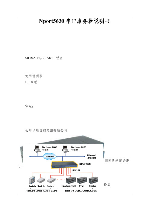
Nport5630串口服务器说明书MOXA Nport 5630 设备使用讲明书1.0版审定:长沙华能自控集团有限公司一、简介MOXA Nport 5600系列产品是一种和后台电脑用网络连接的串口服务器。
NPort 5600 系列多个不同的后台电脑能够共同分享1个Nport 5600设备二、Nport 5600通信线制作引脚号RS232 RS422 / 4线RS485 2线RS4851 DSR2 RTS3 GND TXD+4 TXD TXD-5 RXD RXD- DATA-6 DCD RXD+ DATA+7 CTS GND GND8 DTR三、Nport 5600设置面板和按钮讲明灯:LED灯颜色含义预备灯红正在启动中,长期则是有错误绿正常1-8/16通信信号灯正在接收数据绿正在发送数据按键:键名称- 含义MENU菜单键∧上翻键∨下翻键SEL选择键先在NPORT 5600上把NPORT 5600的IP设置好,具体操作方法如Menu(主选单) NetWork Setting IP Address 设置为192.16 8.X.XNetMask 设置为255.255.255.0四、后台电脑设置在后台电脑中安装好Nport 5600的驱动程,安装完毕后在开始菜单中选择程序,然后再选择刚安装好的NPort Administration Suite N Port Administrator打开后选择Broadcast Search (自动查找在网络内的Nport )配置Nport 5600设置PORTx 端口的通信方式Com Mapping (串口映射)也确实是把NPORT 的PORTx 映射为电脑中的COM到此设置完毕,点击中的Apply 应用刚才的设置。
后台软件中的串口的COM MAPPING中的COM PORT应相对应。
后台软件中的其它设置请参阅MTC的关心文件。
Nport5630串口服务器使用说明
MOXA Nport 5630通信设备使用说明书文件级别:文件编号:MOXA Nport 5630 设备使用说明书1.0版编制:汤浩校核:喻鹏、谭华审定:批准:MOXA Nport 5630通信设备使用说明书长沙华能自控集团有限公司一、简介MOXA Nport 5600系列产品是一种和后台电脑用网络连接的串口服务器。
NPort 5600 系列多个不同的后台电脑可以共同分享1个Nport 5600设备MOXA Nport 5630通信设备使用说明书二、Nport 5600通信线制作Nport 5600 系列串口接线引脚引脚号RS232 RS422 / 4线RS485 2线RS4851 DSR2 RTS3 GND TXD+4 TXD TXD-5 RXD RXD- DATA-6 DCD RXD+ DATA+7 CTS GND GND8 DTRMOXA Nport 5630通信设备使用说明书三、Nport 5600设置面板和按钮说明灯:LED 灯-灯颜色-含义LED灯颜色含义准备灯红正在启动中,长期则是有错误MOXA Nport 5630通信设备使用说明书按键:先在NPORT 5600上把NPORT 5600的IP设置好,具体操作方法如Menu(主选单) → NetWork Setting → IP Address →设置为192.168.X.X→ NetMask →设置为255.255.255.0四、后台电脑设置在后台电脑中安装好Nport 5600的驱动程,安装完毕后在开始菜单中选择程序,然后再选择刚安装好的NPort Administration Suite→ NPort Administrator打开后选择Broadcast Search (自动查找在网络内的Nport )MOXA Nport 5630通信设备使用说明书配置Nport 5600设置PORTx 端口的通信方式MOXA Nport 5630通信设备使用说明书Com Mapping (串口映射)也就是把NPORT 的PORTx 映射为电脑中的COMMOXA Nport 5630通信设备使用说明书。
串口服务器Nport Server 安装使用说明
串口服务器Nport Server 安装使用说明串口服务器Nport Server是将TCP/IP协议网络信号与485/232通讯信号进行互相转换的网络设备,在通讯领域的应用十分广泛,利用它我们可以将采用485/232通讯的设备延伸的网络(局域网或广域网)中的任何终端。
在本工程中共采用两个串口服务器,一个和南瑞监测系统(含垂线、右岸引张线、扬压力、多点位移计、静力水准、坝后裂缝)相连,其IP地址为:10.144.84.4,网关为10.144.84.1,子网掩码为:255.255.255.0,其通讯速率设置为1200bps;另一个和联能监测系统(含内观、左岸引张线)相连,其IP地址为:10.144.84.5,网关为10.144.84.1,子网掩码为:255.255.255.0,其通讯速率设置为2400bps。
1.口服务器Nport Server 安装1.1硬件安装电源线接入:将由电源适配器输出的电缆接入串口服务器的电源端,由于串口服务器工作电源要求是直流DC12V~30V,因此我们在接电源之前应先检查电源适配器的输出电压是否满足要求(12V~30V),在接线时要注意电源正负别接反,适配器的电源正接串口服务器电源端的正,适配器的电源正接串口服务器电源端的正。
网络线接入:利用网线将串口服务器的网络接口端与网络交换机相连即可。
485通讯线接入:串口服务器有232和485/422两个端口,在本项目中只用到485端口,将485端口的T+端接到485中继器的B端,将485端口的R+端接到485中继器的A端,将485端口的G端接到485中继器的G端。
需要说明的是485中继器是对485信号进行放大整形的设备,共有两个485端口,这两个端口通讯放大是双向的,在接到串口服务器时任选485中继器的一个端口即可,485中继器的另一端口和监测系统通讯线相连(监测系统通讯线的红线接485中继器的A端,黑线接485中继器的B端,屏蔽线接485中继器的G端),在本监测系统中共利用两个485中继器,一个通讯速率是1200bps,用在南瑞系统,一个通讯速率是2400bps,用在南瑞系统。
串口服务器参数
Moxa 串口服务器16口机架式型号:NPort 5630-16 报价:4800.00 8口机架式型号:NPort 5630-8 报价:4000.008口桌面型型号:NPort 5650-8-DT 报价:4200.00机架式型号设备参数如下:NPort 5630-16、NPort 5630-8以太网端口数量:1速率:10/100 Mbps,自适应MDI/MDIX 接头:8针RJ45电磁隔离保护:内建1.5 KV光纤接口(支持-M-SC和-S-SC)串口端口数量:8或16个串口类型:NPort 5630:RS-422/485接头:RJ45 (8针)串口保护:全信号15 KV ESD保护RS-485数据流向控制:ADDC® (数据流向自动控制功能)RS-485上拉/下拉电阻:1 KΩ,150 KΩ (NPort 5650-8/16)串口通讯参数数据位:5,6,7,8停止位:1,1.5,2校验位:None,Even,Odd,Space,Mark流量控制:DSR/DTR和RTS/CTS(仅RS-232),XON/XOFF波特率:50 bps ~ 921.6 Kbps串口信号RS-232:TxD,RxD,RTS,CTS,DTR,DSR,DCD,GND RS-422:Tx+,Tx-,Rx+,Rx-,GNDRS-485-4w:Tx+,Tx-,Rx+,Rx-,GNDRS-485-2w:Data+,Data-,GND软件网络协议:ICMP,IP,TCP,UDP,DHCP,BOOTP,Telnet,DNS,SNMP V1,HTTP,SMTP,SNTP,ARP,PPP,SLIP,RTelnet,RFC2217配置方式:Web Console,Telnet Console,Windows UtilityWindows Real COM驱动:Windows 95/98/ME/NT/2000,Windows XP/2003/Vista/2008/7 x86/x64,Embedded CE 5.0/6.0,XP EmbeddedFixed TTY驱动:SCO Unix,SCO OpenServer,UnixWare7,UnixWare 2.1,SVR 4.2,QNX 4.25,QNX 6,Solaris 10,FreeBSD,AIX 5.x,HP-UX 11iLinux Real TTY驱动:Linux kernel 2.4.x,2.6.x迷你屏幕和按钮LCD面板:提供液晶显示屏按钮:提供4个按钮,方便现场配置机械特性外壳:金属,IP30防护等级重量:NPort 5630-8:3380 gNPort 5630-16:3400 g尺寸:无挂耳:440 x 45 x 198 mm (17.32 x 1.77 x 7.80 in)有挂耳:480 x 45 x 198 mm (18.90 x 1.77 x 7.80 in)工作环境工作温度:标准型号:0 ~ 55 °C (32 ~ 131 °F)宽温型号:-40 ~ 75 °C (-40 ~ 167 °F)存储温度:-40 ~ 75 °C (-40 ~ 167 °F)工作湿度:5 ~ 95% (无凝露)电源要求输入电压:NPort 5610/5630/5650:100 ~ 240 VAC,47 ~ 63 hz功耗:NPort 5630-8/16:152 mA @ 100 VAC,98 mA @ 240 VAC安规认证Safety:UL 60950-1,EN 60950-1EMC:CE,FCCEMI:EN 55022 Class A,FCC Part 15 Subpart-B Class-A EMS:EN 55024Medical:EN 60601-1-2 Class B,EN 55011可靠性自动重启触发器:内建WDT(看门狗定时器)MTBF(平均故障间隔时间):NPort 5630-8:118,405小时NPort 5630-16:91,483小时保修保修期:5年桌面型号设备参数如下:NPort 5650-8-DTLAN以太网:2 10/100 Mbps,RJ45保护:内嵌的1.5 KV电磁隔离NPort 5610-8-DT串口介面接口:RS-232接口数量:8接口类型:RJ45 (8-pin) 或DB9 (male)信号:TxD,RxD,RTS,CTS,DTR,DSR,DCD,GND NPort 5650-8-DT串口介面接口:RS-232/422/485接口数量:8接口类型:RJ45 (8-pin) 或DB9 (male)信号:RS-232:TxD,RxD,RTS,CTS,DTR,DSR,DCD,GND RS-422:Tx+,Tx-,Rx+,Rx-,GNDRS-485 (2线):Data+,Data-,GNDRS-485 (4线):Tx+,Tx-,Rx+,Rx-,GND信号保护:所有信号提供15 KV ESD保护信号保护:2 KV (NPort 5650I-8-DT)RS-485数据流向:ADDC™(专利保护的数据流向自动控制功能)电源线保护4 KV burst (EFT),EN61000-4-42 KV surge,EN61000-4-5内嵌高级功能HMI:LCM显示,带4个按键内嵌的蜂鸣器内嵌实时时钟内嵌看门狗实时时钟串行通信参数校验位:None,Even,Odd,Space,Mark数据位:5,6,7,8停止位:1,1.5,2流向控制:RTS/CTS,XON/XOFF,DSR/DTR (仅RS-232)速率:50 bps ~ 921.6 Kbps软件特点协议:ICMP,IP,TCP,UDP,DHCP,BOOTP,Telnet,DNS,SNMP,HTTP,SMTP,SNTP,Rtelnet,ARP,RFC2217工具:NPort管理员应用于Windows 95/98/ME/NT/2000/XP/2003/Vista驱动支持:Windows 95/98/ME/NT/2000//XP/2003/2003x64/Vista/Vista x64 Real COM driver/Linux Real TTYdriver/SCO Unix/SCO OpenServer 5/OpenServer 6/UnixWare7/UnixWare 2.1/SVR4.2/QNX 4.25/QNX 6/Solaris 10/FreeBSD 5/FreeBSD 6配置:Web浏览器/串口telnet console口,或Windows工具电源需求电源输入:12 ~ 48 VDC电源功耗:NPort 5650-8-DT:580 mA for 12V,156 mA for 48V机械特性材料:SECC钢板(1mm)尺寸(W × H × D):197 x 135.5 x 44 mm (无ears)229 x 135.5 x 46 mm (含ears)197 x 135.5 x 53 mm (with DIN-Rail kit on bottom panel)毛重:NPort 5650-8-DT:1.77 kg工作环境工作温度:0 ~ 55 °C (32 ~ 131 °F),5 ~ 95% RH存储温度:-20 至70°C (-4 至158°F),5 至95% RH通过认证EMC:CE: EN55022 Class A/EN55024FCC: FCC Part 15 Subpart B,Class A安全:UL: UL60950-1TÜV: EN60950-1保修期5 年国产串口服务器NC608-8M 8口桌面型参考价格:1500 NC608-8 8口机架型参考价格:2200 NC616-16 16口机架型参考价格:3200国产设备参数与Moxa类似。
串口服务器说明书
1台
电源适配器
1 个 DC5V/1A 1 个 DC5V/1A 1 个 DC5V/1A 1 个 DC5V/1A 1 个 DC5V/2A
AC220V 线缆 AC220V 线缆 AC220V 线缆 AC220V 线缆
运行 upgrad.exe 搜索不到串口服务器的 IP 地址
b) 串口程序不能打开串口
c) 不能收发数据
d) 忘记之前设置的密码
e) 收发数据是乱码
f) PC 用 IE 时打不开,在地址栏输入 IP 时能打开
g) IE 打开复杂网页或下载大的文件,打不开或者不全
h) PPP 连接不通
i) 作为 TCP server 时,不能被连接
1台
两串口服务器(2 路 RS232)
1台
两串口服务器(2 路 RS485/422)
1台
四串口服务器(三合一)
1台
八串口服务器(三合一)
1台
十六串口服务器(16 路 RS232)
1台
十六串口服务器(16 路 RS485/422)
1台
三十二串口服务器(32 路 RS232)
1台
三十二串口服务器(32 路 RS485/422)
保存温度 境
保存湿度
-20℃————85℃ 5%————95%
认证
FCC、CE
电源
DC 5V、1A
AC 220V
外
材质
金属外壳
观
尺度
97×65×22mm
113×77×23mm
160×90×30mm
标准 19 英寸,1U 高度
b)产品配置表(以一套设备为准)
配置
串口服务器
型号
主机
单串口服务器(三合一)
关于Nport 设置TCPservice模式说明书

4,设备库协议填TCP,串口类型填ip+冒号+端口如:192.168.1.248:4001,因客户端BUG,此项需要在数据库修改。如图:
5,最后,注意在loncomip配置LoaderBundle.xml,开启TCP就行。
和由于公司软件和nport虚拟串口模式常常失灵为了解决此问题特作一简单文档与大家共享之虚拟串口模式常常失灵为了解决此问题特作一简单文档与大家共享之bylisbs设置步骤以温湿度举例说明
由于
设置步骤,以温湿度举例说明:
1,登录Nport,如下图(可以通过网页以及Nport客户端)
2.从左边的树形找到Operating Setting,最上面一个常数,Operation mode选择TCP serverMode,其他ห้องสมุดไป่ตู้认即可。打开如图:
Nport5630串口服务器使用说明
Nport5630串口服务器使用说明Nport5630串口服务器是一款功能强大的设备,可以将串口设备连接到IP网络,实现远程管理和控制。
本文将详细介绍Nport5630串口服务器的使用方法和操作流程,以帮助用户更好地利用该设备。
1. 设备介绍Nport5630串口服务器是一种专门用于串口设备的远程管理和控制的设备。
它可以将串口设备转换为TCP/IP网络数据,实现远程控制和监控。
Nport5630具有多种通信接口,包括RS-232、RS-422和RS-485,可适应不同的串口设备。
2. 连接配置使用Nport5630之前,首先需要进行连接配置。
将串口设备通过串口线缆连接到Nport5630的串口接口上,同时将网络线缆连接到其以太网接口上。
确保电源供应正常,设备接口连接稳定。
3. IP设置接下来,需要对Nport5630进行IP设置。
打开终端程序,通过串口连接到Nport5630。
输入设备提供的默认IP地址和用户名密码进行登录。
进入管理界面后,选择网络设置,按照实际网络环境设置设备的IP地址、子网掩码和默认网关。
保存设置并重新启动设备,确保新的IP设置生效。
4. 端口配置配置Nport5630的串口参数,确保与连接的串口设备保持一致。
通过终端程序连接到Nport5630后,选择端口配置,设置相应的串口参数,包括串口类型、波特率、数据位、校验位和停止位等。
根据实际需求进行设置,并保存配置。
5. 远程管理完成连接配置和端口配置后,就可以通过网络远程管理和控制串口设备了。
在计算机上打开浏览器,输入Nport5630的IP地址,登录设备管理界面。
界面提供了多种功能选项,包括串口调试、远程命令、虚拟串口和数据转发等。
根据实际需求选择相应的功能,并进行相关设置和操作。
6. 串口调试Nport5630提供了串口调试功能,可以帮助用户实时监测和调试串口设备。
在设备管理界面中选择串口调试,并选择要调试的串口,打开调试窗口后,即可实时查看串口设备的输出信息。
NPort-5630串口接口服务器在天福项目中的应用
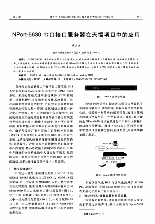
该 设 备 安 装 简 单 , 需 在 网 络 柜 内 和 安 装 支 只 架 水 平 固 定 安 装 即 可 , 三 方 设 备 与 N ot 6 0 第 p r5 3 一
可 以 冗 余 设 置 , 现 现 场 串 口 设 备 与 D S之 间 的 实 C 数 据交 换 。
中 图 分 类 号 : P 9 文 献 标 识 码 :B 文章 编 号 : 0 03 3 ( 0 1 0 —2 3 T 33 10 — 2 2 1 )20 3  ̄3 9
贵 州天 福合 成氨 及二 甲醚项 目主 体装 置 D S C
系 统采 用美 国 H ny e 公 司生 产 的 E K 30 o ew l l P SR 0
中心 控 制 室 , 必 造 成 整 个 控 制 室 布 局 凌 乱 , 操 势 且
SERVER
I er nt net 一
作界 面增 多 也 使精 减 操 作 人 员 变 得 不 现 实 , 需 故 将这 些 子 系统 与 作 为 主 控 制平 台 的 D S建 立 数 C
据通 信 、 交换 , 得通 信技 术得 以大量应 用 。 使
共 计 3对 , 接 在 E K 衔 P S系 统 F E容 错 以 太 网 上 。 T 其 中一对 为煤 气 化 装 置 (6 口) 一 对 为 氨 醇 (6 1 , 1
口 ), 一 对 二 甲 醚 装 置 ( 口 ) 两 个 Np r一6 0 另 8 , ot5 3
下 面 以 煤 气 化 D S与 煤 气 化 热 风 炉 S -0 C 73 0 P C通 讯 为 例 , 绍 N o -6 0 串 口接 口服 务 器 L 介 pr53 t 在 天福化 工 实际 工程 中的应用 。
串口服务器配置手册

立体仓库系统硬件配置手册无锡中鼎物流设备有限公司2015年1月编制1.硬件介绍MOXA串口联网服务器NPORT5360特点- 以太网口支持100/10M自适应,串口支持RS-422,RS-485(2w/4w)- 低成本、信用卡大小- 支持Windows/Linux COM串口驱动程序模式- 提供包括TCP Server、TCP Client、UDP Server/Client和Ethernet Modem在内的不同socket操作模式- 无需PC、可通过网络连接两个串口设备的对等连接模式- 易于使用、可用于批量安装的Windows工具- 所有信号内置15 KV突波保护- 支持网络管理协议SNMP MIB-II- 可通过网络Web/Telnet进行配置2.串口服务器配置MOXA针对串口联网服务器开发了软件NPort Administrator,方便用户配置,下面我就介绍如何用Nport Administration 配置NPORT产品。
⑴安装软件Nport Administration如下图所示安装Nport Administration Suite⑵连接串口服务器安装Nport Administration Suite后连接立库系统内网,需要配置与立体库同一网段IP地址。
本立库系统串口服务器IP地址为192.3.15.252.注意:配置IP地址时请勿配置设备占用的IP地址,否则可能会导致设备无法正常运行。
打开软件,如图:图三点击Search,可以搜索到局域网中所有的NPORT设备,包括和主机IP不同网段的NPORT设备。
搜索到设备如下图:图四如图可以显示设备的型号,MAC地址,IP地址,以及设备的名称。
(默认IP:192.168.127.254)⑶配置串口服务器选中要配置的设备,点击右键——Configuer,或者是双击,进入设备配置界面,如图:图5如图五,Basic界面可以设置设备的名称,设备的时钟(默认读取主机时钟),以及登陆设备的方式。
JetBox 5630 与 JetWave 2311 的 OpenVPN 配置指南说明书
將頁面往下拉 點選 “Apply”
Static mode
• Client 儲存設定
到 “Save” 點選 “Save to Flash”
Static mode
• 確認VPN連線狀態
到 “VPN”=> “Status”, 可以檢查VPN的連線狀態
• 準備工作 • IP 配置範例 • Static mode • TLS-mode
Static mode
• 開啟Server的OpenVPN連線
回到Server的網頁, 到 ”VPN”=> ”OpenVPN” 頁面 找到剛才建立的連線, 按下 ”Start” 後, 按下 ”Save & Apply”
Static mode
• Client Network Mode調整
到 “System”=> “Basic Settings”, 將 ”Network Mode” 切換成 ”Router”
TLS-Mode
• 建立新的VPN連線
到 ”VPN”=> “OpenVPN” 輸入連線的名稱並按下 ”Add”
TLS-Mode
• 建立Key
TLS-Mode無法在Web interface建立Key, 要透過下指令的方式建立 用Console連結PC與JetBox 5630, 進入Command mode, 或是用CMD
Hale Waihona Puke TLS-Mode• Server route設定
按 “i” 後, 輸入: • ifconfig-push 10.8.0.3 10.8.0.1 • iroute 192.168.10.0 255.255.255.0
建完按ESC 輸入 ”:wq”
JetBox 5630 HW 用户手册说明书
JetBox 5630HW User Manual0.0.1Copyright NoticeCopyright© 2014 Korenix Technology Co., Ltd.All rights reserved.Reproduction without permission is prohibited.Information provided in this manual is intended to be accurate and reliable. However, the original manufacturer assumes no responsibility for its use, or for any infringements upon the rights of third parties that may result from its use.The material in this document is for product information only and is subject to change without notice. While reasonable efforts have been made in the preparation of this document to assure its accuracy, Korenix assumes no liabilities resulting from errors or omissions in this document, or from the use of the information contained herein.Korenix reserves the right to make changes in the product design without notice to its users.AcknowledgmentsKorenix is a registered trademark of Korenix Technology Co., Ltd.All other trademarks or registered marks in the manual belong to their respective manufacturers.Table of ContentCopyright Notice (2)Acknowledgments (2)Table of Content (3)Chapter 1 Overview (4)Chapter 2 Hardware Specification (5)Chapter 3 Hardware Feature (7)3-1 Mechanical Outline (7)3-2 Front Panel (9)3-3 Bottom View (10)3-4 Wiring the Power Inputs (10)3-5 Grounding JetBox (10)3-6 I/O Connectors (11)3-6-1 Ethernet (RJ-45) (11)3-6-2 SFP (11)3-6-3 USB 2.0 (HOST) (11)3-6-4 RS232/422/485 (DB9) (12)3-6-5 Console (12)3-6-6 Reset Button (12)3-6-7 SD Card Slot (12)3-7 JetBox 5633Gf-w USB Holder (13)3-8 System Login (15)Chapter 4 Customer Service (15)Chapter 1 OverviewOne of the advantages of adopting Korenix JetBox series industrial computers is ready-to-use. All these years, Korenix is devoted to enhance usability and functions of embedded computers in industrial domain. Korenix operating system provides device drivers, protocol stacks, system utilities, supporting services and daemons to make system integration simple. Besides, Korenix also provides application development toolkits for users to build their own applications easily.The stylish compact JetBox 5630Gf-w series are industrial layer 3 VPN routers with Linux computing capability. It is a gateway to connect different network groups such as Ethernet and serial control in a complex networking architecture and manage peripherals at the front-end site. With Gigabit Ethernet, fiber connection and ability of network redundancy, JetBox 5630Gf-w series can be applied in crossroads or highway for flow control and traffic monitoring of remote transportation control. Besides, JetBox 5630Gf-w series are designed with features of compact, reliable and robust to adopt in various industrial vertical markets with hazardous environment such as transportation, surveillance and environmental monitoring.Chapter 2 Hardware SpecificationChapter 3 Hardware Feature 3-1 Mechanical Outline JetBox 5630Gf-w appearanceJetBox 5630Gf-w mechanical outline(160 x 47 x 118 mm)JetBox 5633Gf-w appearanceJetBox 5633Gf-w mechanical outline (160 x 118 x 80 mm)3-2 Front PanelThe front panel includes 3 x 10/100/100 RJ-45 LAN ports, 1 x Gigabit RJ-45/SFP combo WAN port, 1 x RS232/422/485, USB 2.0 sockets and diagnostic LEDs.JetBox 5630Gf-wJetBox 5633Gf-w3-3 Bottom ViewThe bottom side of the JetBox 5630Gf-w series is shown below.3-4Wiring the Power InputsJetBox 5630Gf-w series accepts 9~36V DC power input.1. Insert the positive and negative wires of your DC supply into the V+ and V- contacts of theterminal block connector. The recommended working voltage is DC24V (DC9~36V). 2. Tighten the terminal screws to prevent the DC wires from loosening.3-5 Grounding JetBoxThere is one grounding screw on the bottom side, and please connect the frame grounding of system to the grounding surface to ensure safety and prevent noise to interfere communication.3-6 I/O Connectors3-6-1 Ethernet (RJ-45)JetBox 5630 series provide three RJ-45 LAN ports and one RJ-45/SFP combo WAN port. The RJ-45 isstandard RJ‐45 jack socket.1 83-6-2 SFPJetBox 5630 series provide one RJ-45/SFP combo WAN port. Please don ’t connect Ethernet RJ-45 and SFP transceiver at the same time or use wrong SFP spec which does not match with SFP speed setting, or exception conditions would happen. (Default speed: Gigabit)To change SFP speed you need to reboot the system to make it effective.3-6-3 USB 2.0 (HOST)USB type “A” female connectors for USB peripherals.3-6-4RS232/422/485 (DB9)JetBox 5630 series provide one serial port (DB9). (Default: RS232, RS485 support 4-wire only)1 56 93-6-5ConsoleJetBox provides one 3‐pin connector Console port for debug use.1 33-6-6Reset ButtonThis button is used to make the system reboot or reset to the factory default. Press 3 seconds for system reboot.Press 7 seconds to reset the JetBox to the factory default.3-6-7SD Card SlotThis socket is used for a SD Card and users can put their own applications in it. To access the SD card, you can follow these steps:1.Unscrew five screws of back cover (Please refer to the picture below).2.Then remove the back cover and you can insert or take out the SD card.3-7 JetBox 5633Gf-w USB HolderJetBox 5633Gf-w has extra two USB slots for 3G/wifi USB dongle expansion.To tighten the USB dongle, you have two methods and you can follow these steps:Use the platen to fix the dongle1. Slightly loosen the screws and move the platen to appropriate height according to the size ofdongle.2. Plug the dongle into USB socket.3. Move the platen to press the dongle and tighten the screws.Please do NOT loosen the screws too much or the kits would fall off from JetBox.Use cable ties to fix the dongle1.Take out the cable ties from accessories kit.e the cable tie to thread through the rear side of guide plate.3.Surround the USB dongle then tie up the cable tie.If the kits fall off from JetBox, you can refer to below picture to assembly.3-8 System LoginThere ’re two methods to login JetBox 5630. One is from web GUI, the other is from Linux console. Detail information please refers to Linux and Web user manual.Web GUI Login: admin Password: adminConsole Login: rootPassword: (none)Chapter 4 Customer ServiceKorenix Technology Co., Ltd.Business service: *************************, ***************** Customer service: ********************Web Site: , 。
NPort Z2150 用户手册说明书

NPort Z2150 User’s Manual First Edition, October 2011/product© 2011 Moxa Inc. All rights reserved.NPort Z2150 User’s ManualThe software described in this manual is furnished under a license agreement and may be used only in accordance withthe terms of that agreement.Copyright Notice© 2011 Moxa Inc. All rights reserved.TrademarksThe MOXA logo is a registered trademark of Moxa Inc.All other trademarks or registered marks in this manual belong to their respective manufacturers.DisclaimerInformation in this document is subject to change without notice and does not represent a commitment on the part of Moxa.Moxa provides this document as is, without warranty of any kind, either expressed or implied, including, but not limited to, its particular purpose. Moxa reserves the right to make improvements and/or changes to this manual, or to the products and/or the programs described in this manual, at any time.Information provided in this manual is intended to be accurate and reliable. However, Moxa assumes no responsibility for its use, or for any infringements on the rights of third parties that may result from its use.This product might include unintentional technical or typographical errors. Changes are periodically made to the information herein to correct such errors, and these changes are incorporated into new editions of the publication.Technical Support Contact Information/supportMoxa AmericasToll-free: 1-888-669-2872 Tel: +1-714-528-6777 Fax: +1-714-528-6778Moxa China (Shanghai office) Toll-free: 800-820-5036Tel: +86-21-5258-9955 Fax: +86-21-5258-5505Moxa EuropeTel: +49-89-3 70 03 99-0 Fax: +49-89-3 70 03 99-99Moxa Asia-PacificTel: +886-2-8919-1230 Fax: +886-2-8919-1231Table of Contents1.Introduction ...................................................................................................................................... 1-1Overview ........................................................................................................................................... 1-2 Package Checklist ............................................................................................................................... 1-2 Product Features ................................................................................................................................ 1-2 Product Specifications ......................................................................................................................... 1-2 Serial Port Pin Assignments .................................................................................................................. 1-4 2.Getting Started.................................................................................................................................. 2-1Overview ........................................................................................................................................... 2-2 Panel Layout ...................................................................................................................................... 2-2 LED Indicators .................................................................................................................................... 2-2 DIP Switch ......................................................................................................................................... 2-3 Pull High/Low Resistors for RS-422/485 ................................................................................................. 2-3 Function Block .................................................................................................................................... 2-4 Connecting the Hardware..................................................................................................................... 2-4 Connecting the Power ......................................................................................................................... 2-5 Connecting to a Serial Device ............................................................................................................... 2-5 3.Installing and Configuring the Software ........................................................................................... 3-1Overview ........................................................................................................................................... 3-2 ZigBee Configuration Utility.................................................................................................................. 3-2 Configuring NPort Device ..................................................................................................................... 3-5 Import/Export .................................................................................................................................... 3-9 Upgrading NPort Firmware ................................................................................................................. 3-10 Refresh ........................................................................................................................................... 3-12 Options ........................................................................................................................................... 3-12 A.ZigBee Introduction .......................................................................................................................... A-1Device Type ....................................................................................................................................... A-1 Network Topology ............................................................................................................................... A-11IntroductionThe following topics are covered in this chapter:❒Overview❒Package Checklist❒Product Features❒Product Specifications❒Serial Port Pin AssignmentsOverviewThe NPort Z2150 provides a reliable wireless serial converter with support for serial-to-ZigBee communications.The following architecture is the application overview for the NPort Z2150. The Z2150 can act as ZigBeeCoordinator, ZigBee Router or ZigBee End Device. Any serial device can be connected by the Z2150 andexchange data via PAN.Package ChecklistBefore installing the NPort Z2150, verify that the package contains the following items:Standard Accessories•NPort Z2150•Document & Software CD•Power adaptor (wide temperature models excluded)•Warranty statement•Quick Installation Guide• 2.4 GHz omni-directional antennaOptional Accessories•DK-35A: DIN-rail mounting kit (35 mm)NOTE: Please notify your sales representative if any of the above items are missing or damagedProduct Features•Instant connection of any serial device to ZigBee network•RS-232/422/485 ports supporting baudrates up to 230.4 Kbps•Friendly configuration with serial console•Secure data access with AES•Supports End Device, Router, and Coordinator roles.Product SpecificationsZigBee InterfaceRF Standard: 802.15.4Frequency Band: 2.4 GHzInterface Immunity: DSSSRF Data Rate: 250 KbpsRx sensitivity: -96 dBmTx Power: 4.5 dBm (Max)Transmission Distance: Up to 100m (in open areas)Antenna: 2dBPAN ID: 0x0000 – 0xFFFDNode ID: 00 - 99RF Channel: 11-26 (16 channels)Device Type: Coordinator, Router, End DeviceNetwork Topology: Star, Mesh, TreeSecurity: 128 bit AES encryption algorithmsSerial InterfaceNumber of Port: 1Serial Standards: RS-232/422/485Connector: DB9 maleSerial Line Protection: 15KV ESD protection for all signalsRS- 485 Data Direction Control: ADDC (Automatic Data Direction Control) Serial Communication ParametersData Bits: 8Stop Bits: 1, 2Parity: None, Even, OddFlow Control: RTS/CTS, XON/XOFFBaudrate: 50 bps to 230.4KbpsSerial SignalsRS-232: TxD, RxD, RTS, CTS, DTR, DSR, DCD, GNDRS-422: TxD+, TxD-, RxD+, RxD-, GNDRS-485-4w: TxD+, TxD-, RxD+, RxD-, GNDRS-485-2w: Data+, Data-, GNDSoftwareZigBee Configuration UtilityHardwareDIP Switch (on the box):Console/Operation Mode, ReservedDIP Switch (inside the box):SW1/2: Pull high/low resistorSW3: Termination for RS-422/485Reset Button: Reset to defaultPhysical CharacteristicsWeight: 340gDimension:Without ears: 52 x 80 x 22 mm (2.05 x 3.15 x 0.87 in)With ears: 75 x 80 x 22 mm (2.95 x 3.15 x 0.87 in) Environmental LimitsOperating Temperature:Standard Models: 0 to 55°C (32 to 131°F)Wide Temp. Models: -40 to 75°C (-40 to 167°F)Operating Humidity: 5 to 95% RHStorage Temperature:-40 to 85°C (-40 to 185°F)Power RequirementsInput Voltage: 12 to 48 VDCPower Consumption: 45 mA @ 12 VConnector: Power JackRegulatory ApprovalsEMC: CE (EN55022 Class A, EN55024), FCC Part 15 Subpart B Class ASafety: UL (UL60950-1), LVD (EN60950-1)ReliabilityAutomatic Reboot Trigger: Built-in WDT (watchdog timer)MTBF (meantime between failures): 2542774 hrsWarrantyWarranty Period: 5 yearsDetails: See /warrantySerial Port Pin Assignments2Getting StartedThe following topics are covered in this chapter:❒Overview❒Panel Layout❒LED Indicators❒DIP Switch❒Pull High/Low Resistors for RS-422/485❒Function Block❒Connecting the Hardware❒Connecting the Power❒Connecting to a Serial DeviceOverviewThis chapter presents the hardware features of the NPort Z2150 and explains how to connect the hardware. Panel LayoutLED IndicatorsThere are three LEDs on NPort Z2150. The LED descriptions are as follows:NO. LED Name LED Color Descriptions1 Ready Green On: System power onFlashing: 1) Device locating 2) Reset button pushed down Fault Red On: System power onFlashing:1) If ZigBee LED is off, it means Node ID conflict2) If ZigBee LED is on, it means Destination Node ID disappeared2 ZigBee Green Coordinator:On: Initialized ZigBee PAN successfullyBlinking: ZigBee Tx/RxOff: Initialized ZigBee PAN failRouter:On: Joined ZigBee PAN successfullyBlinking: ZigBee Tx/RxOff: Failed to join ZigBee PANEnd Device:On: Joined ZigBee PAN successfullyBlinking: ZigBee Tx/RxOff: Failed to join ZigBee PAN/Parent node removed.3 Serial Tx Green Serial data output to serial portSerial Rx Orange Serial data input from serial portDIP SwitchSerial Connection 1Console Mode ONOperation Mode OFFNote: Reserved 2 for future usage.Pull High/Low Resistors for RS-422/485 You may need to set the pull high/low resistors when termination resistors are used for certain RS-422 or RS-485 environments.SW 1 2 3 4Pull High Pull Low Terminator ReservedON 1KΩ1KΩ120KΩDefault OFF 150KΩ150KΩFunction BlockConnecting the HardwareThe following guidelines will help ensure trouble-free signal communication with the NPort.•Use separate paths to route wiring for power and devices to avoid interference. Do not run signal or communication wiring and power wiring in the same wire conduit. The rule of thumb is that wiring thatshares similar electrical characteristics can be bundled together.•If power wiring and device wiring paths must cross, make sure the wires are perpendicular at the intersection point.•Keep input wiring and output wiring separate.•Label all wiring to each device in the system for easier testing and troubleshootingConnecting the PowerConnect the VDC power line (12 to 48 V) to the NPort’s power jack. If power is properly connected, the “Ready”LED will initially glow red. When the system is ready, the “Ready” LED will turn green.Connecting to a Serial DeviceUse a serial cable to connect your serial device to the serial port on the NPort.3 Installing and Configuring the SoftwareThe following topics are covered in this chapter:❒Overview❒ZigBee Configuration Utility❒Configuring NPort Device❒Import/Export❒Upgrading NPort Firmware❒Refresh❒OptionsOverviewThis chapter describes how to install and use the ZigBee Configuration Utility. These items are located on the Documentation & Software CD that is provided with the NPort Z2150.ZigBee Configuration Utility is a utility for the management of NPort device servers over serial ports. You may also use ZigBee Configuration Utility to upgrade the firmware.ZigBee Configuration UtilityInstalling ZigBee Configuration Utility1.The main installation window will open when you insert the Document & Software CD. Click [INSTALLUTILITY] to proceed. Once the program starts running, click [Yes] to proceed.2.The installation wizard will open. Click [Next] to proceed.3.Select a destination directory and click [Next] to proceed4.Verify the installation parameters and click Install to proceed.5.The wizard will begin installing the files. After the files have been installed, click [Finish] to complete theinstallation.Finding NPort Z2150 Series on SerialYou can use ZigBee Configuration Utility to look up or set configuration settings of any NPort on the serial.All NPort units with SW1 ON (in Console mode) that are connected to the serial COM port of a PC can be found and configured.1.In ZigBee Configuration Utility, click Add on the main toolbar.2.Select the COM port number which is connected to the NPort device, and click Connect to find device. Inaddition, you can select multiple target COM ports.3.The utility will search for NPort device servers.4.When the search is complete, NPort units that were found will be listed in the main window.Removing target COM portAfter configuring the NPort device, you might want to remove the target COM port from the device list.1.Select the devices which you would like to remove. You can select multiple ports2.Click Delete on the main toolbar.3.Click Yes to confirm you want to delete these selected COM port. If you want to cancel the action, click No.4.The selected COM ports will be removed from the device list.Configuring NPort Device1.Once ZigBee Configuration Utility has found NPort device servers on the serial, you can modify any unit’sconfiguration. Select the desired NPort in the main window and click Config on the main toolbar2.In the General tab, you can change the device name. It acts like a nickname for the target NPort device.3.In the Serial tab, you can configure Baud Rate, Parity, Stop Bit, and Interface Mode.Serial Port DescriptionBaud Rate 50 bps to 230400 bpsParity None, Odd, EvenData Bits 8Stop Bits 1, 2Interface RS-232, RS-422, RS-4854.In the ZigBee tab, you can configure ZigBee parameters. The details of parameters are in the table below.Parameter DescriptionDevice type The device can take three different device types: Coordinator, Router, andEnd Device.PAN ID The PAN identifier. The range is from 0 to 0xFFFD.Channel The 2.4GHz channel. The range is from 11 to 26.Topology Supports three kinds of topology: Star, Tree and Mesh.Output power Supports -20, -16, -12, -8, -4, -1.5, 1, 4.5 dBm. Default value is 4.5Device Type AdvancedSettingsDescriptionRouter/ End Device Localnode IDThe identifier for each ZigBee node. The range is from 0 to 99.(Default value is 0 for a Coordinator of NPort Z2150 or Z3150) DestinationNode IDAssign the identifier of desired ZigBee node. The range is from 0 to 99.Coordinator Mode Transmission mode: Transparent or AddressableTransparent: All data comes in via the serial port, Coordinator will broadcastto the desired ZigBee node.Addressable: All data comes to the Coordinator via the serial port, theCoordinator will send to the desired ZigBee node directly.Start Byte The head of addressable mode command format on Coordinator. Defaultvalue is # (0x23)5.In the Security tab, you can enable 128-bit AES encryption for Zigbee security. After enabling security, youmust enter the 16-byte key for AES encryption. Finally, click OK to enable the new Configuration.6.The selected NPort will be restarted by ZigBee Configuration Utility with the new configuration.Import/ExportExporting a Configuration1.Once ZigBee Configuration Utility has found NPort device servers on the serial port, you can export anyunit’s configuration. Right-click the desired NPort in the main window and select Export.2.Select the export directory and click OK to proceed.3. A message will pop up confirming a successful export.4.The configuration file will be saved in the .txt format.Importing a Configuration1.Once ZigBee Configuration Utility has found NPort device servers on the serial port, you can import a configfile to any unit. Right-click the desired NPort in the main window and select Import.2.Select the file to import and click OK to proceed.3.If you import the configuration file successfully, the following message will pop up.Upgrading NPort FirmwareOnce ZigBee Configuration Utility has found NPort device servers on the serial port, you can upgrade any unit’s firmware.1.Select the desired NPort in the main window and click Upgrade firmware.2.Select the new firmware file and click OK to proceed. To obtain the latest firmware for the NPort Z2150, visit.3.The utility will begin upgrading the firmware for the selected unit. Do not disconnect or power off the unitwhile the firmware is being upgraded.4.When the displayed status is “OK”.Refresh 1.Once ZigBee Configuration Utility has found NPort device servers on the serial port, you can monitor all unitstatuses manually. Right-click the desired NPort in the main window and select Refresh.2. After clicking the Refresh button, the desired NPort device will update its information. This way, you canmonitor the status of devices. Moreover, the monitor items is defined to what you selected in the Optionwindow.Options1. In ZigBee Configuration Utility, click View Options on the menu bar.2.Select or de-select items. Use the single arrowhead buttons to move highlighted items from one box to theother. Use the double arrowhead buttons to move all items in one box to the other.AZigBee Introduction The ZigBee standard is a set of low-data-rate, short-range wireless networking communication protocols.ZigBee supports a maximum data rate of 250 kb/s and works in the 868 MHz, 915 MH and 2.4 GHz frequency bands. ZigBee is particularly common in battery-powered and energy-limited applications where thosequalities are valued. In many ZigBee applications, the ZigBee wireless devices spend most of their time inpower-saving or sleep mode, so they can go years between battery replacements.Home patient monitoring is a good example of a typical ZigBee application. The heart rate and blood pressure sensors worn at home by patients are often connected to a worn ZigBee device that periodically transmit sensor data to a local server, such as a home PC, for initial analysis. The local server can then use an Internetconnection to forward this medical data on to medical professionals for more detailed analysis.Device TypeThe ZigBee standard uses slightly different terminology:ZigBee coordinator: An IEEE 802.15.4-2003 PAN coordinator.ZigBee end device: An IEEE 802.15.4-2003 RFD or FFD participating in a ZigBee network, which is neither the ZigBee coordinator nor a ZigBee router.ZigBee router: An IEEE 802.15.4-2003 FFD participating in a ZigBee network, which is not the ZigBeecoordinator but may act as an IEEE 802.15.4-2003 coordinator within its personal operating space, that iscapable of routing messages between devices and supporting associations.Network TopologyThe ZigBee network layer (NWK) supports star, tree, and mesh topologies. In a star topology, the network is controlled by one single device called the ZigBee coordinator. The ZigBee coordinator is responsible forinitiating and maintaining the devices on the network. All other devices, known as end devices, directlycommunicate with the ZigBee coordinator. In mesh and tree topologies, the ZigBee coordinator is responsible for starting the network and for choosing certain key network parameters, but the network may be extended through the use of ZigBee routers. In tree networks, routers move data and control messages through thenetwork using a hierarchical routing strategy. Tree networks may employ beacon-oriented communication as described in the IEEE 802.15.4-2003 specification. Mesh networks allow full peer-to-peer communication.ZigBee routers in mesh networks do not currently emit regular IEEE 802.15.4-2003 beacons. This specification describes only intra-PAN networks, that is, networks in which communications begin and terminate within the same network.In the star topology, every device in the network can communicate only with the PAN coordinator. A typicalscenario in a star network formation is that an device, programmed to be a PAN coordinator, is activated and starts establishing its network. The first thing this PAN coordinator does is select a unique PAN identifier that is not used by any other network in its radio sphere of influence—the region around the device in which its radio can successfully communicate with other radios. In other words, it ensures that the PAN identifier is not usedNPort Z2150 User's Manual ZigBee Introduction by any other nearby network.In a Mesh topology each device can communicate directly with any other device if the devices are placed close enough together to establish a successful communication link. Any devices in a peer-to-peer network can play the role of the PAN coordinator. One way to decide which device will be the PAN coordinator is to pick the first device that starts communicating as the PAN coordinator. In a peer-to-peer network, all the devices thatparticipate in relaying the messages are devices because devices are not capable of relaying the messages.However, an device can be part of the network and communicate only with one particular device (a coordinator or a router) in the network.ZigBee supports a tree topology. In this case, a ZigBee coordinator (PAN coordinator) establishes the initial network. ZigBee routers form the branches and relay the messages. ZigBee end devices act as leaves of the tree and do not participate in message routing. ZigBee routers can grow the network beyond the initial network established by the ZigBee coordinator.Note: Please refer to the book: “ZigBee Wireless Networks and Transceivers”。
Nport5630串口服务器说明书
文件级别:文件编号:MOXA Nport 5630 设备使用说明书1.0版编制:汤浩校核:喻鹏、谭华审定:批准:长沙华能自控集团有限公司一、简介MOXA Nport 5600系列产品是一种和后台电脑用网络连接的串口服务器。
NPort 5600 系列多个不同的后台电脑可以共同分享1个Nport 5600设备二、Nport 5600通信线制作Nport 5600 系列串口接线引脚引脚号RS232 RS422 / 4线RS485 2线RS4851 DSR2 RTS3 GND TXD+4 TXD TXD-5 RXD RXD- DATA-6 DCD RXD+ DATA+7 CTS GND GND8 DTR三、Nport 5600设置面板和按钮说明灯:LED 灯-灯颜色-含义LED灯颜色含义准备灯红正在启动中,长期则是有错误绿正常1-8/16通信信号灯正在接收数据绿正在发送数据按键:键名称- 含义MENU菜单键∧上翻键∨下翻键SEL选择键先在NPORT 5600上把NPORT 5600的IP设置好,具体操作方法如Menu(主选单) → NetWork Setting → IP Address →设置为192.168.X.X→ NetMask →设置为255.255.255.0四、后台电脑设置在后台电脑中安装好Nport 5600的驱动程,安装完毕后在开始菜单中选择程序,然后再选择刚安装好的NPort Administration Suite→ NPort Administrator打开后选择Broadcast Search (自动查找在网络内的Nport )配置Nport 5600设置PORTx 端口的通信方式Com Mapping (串口映射)也就是把NPORT 的PORTx 映射为电脑中的COM到此设置完毕,点击中的Apply应用刚才的设置。
后台软件中的串口的COM MAPPING中的COM PORT应相对应。
Nport5630串口服务器说明介绍模板之欧阳数创编
文件级别:文件编号:MOXA Nport 5630 设备使用说明书1.0版编制:汤浩校核:喻鹏、谭华审定:批准:长沙华能自控集团有限公司一、简介MOXA Nport 5600系列产品是一种和后台电脑用网络连接的串口服务器。
NPort 5600 系列多个不同的后台电脑可以共同分享1个Nport 5600设备二、Nport 5600通信线制作Nport 5600 系列串口接线引脚引脚RS232 RS422 / 4线RS485 2线RS485号1 DSR2 RTS3 GND TXD+4 TXD TXD-5 RXD RXD- DATA-6 DCD RXD+ DATA+7 CTS GND GND8 DTR三、Nport 5600设置面板和按钮说明灯:LED 灯-灯颜色-含义LED灯颜色含义准备灯红正在启动中,长期则是有错误绿正常1-8/16通信信号灯正在接收数据绿正在发送数据按键:键名称- 含义MENU菜单键∧上翻键∨下翻键SEL选择键先在NPORT 5600上把NPORT 5600的IP设置好,具体操作方法如Menu(主选单) NetWork Setting IP Address 设置为192.168.X.XNetMask 设置为255.255.255.0四、后台电脑设置在后台电脑中安装好Nport 5600的驱动程,安装完毕后在开始菜单中选择程序,然后再选择刚安装好的NPort Administration Suite NPortAdministrator打开后选择Broadcast Search (自动查找在网络内的Nport )配置Nport 5600设置PORTx 端口的通信方式Com Mapping (串口映射)也就是把NPORT 的PORTx 映射为电脑中的COM到此设置完毕,点击中的Apply应用刚才的设置。
后台软件中的串口的COM MAPPING中的COM PORT 应相对应。
后台软件中的其它设置请参阅MTC的帮助文件。
OSRAM Opto Semiconductors OSLON LED 5630 产品说明书
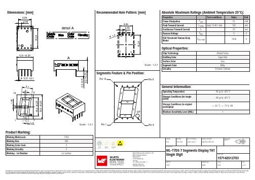
Dimensions: [mm]detail AScale - 1,5:1157142S12703Schematic:157142S12703157142S12703157142S12703157142S12703157142S12703157142S12703T e m p e r a t u r eT T T 157142S12703Cautions and Warnings:The following conditions apply to all goods within the product series of Optoelectronic Components of Würth Elektronik eiSos GmbH & Co. KG:General:•This optoelectronic component is designed and manufactured for use in general electronic equipment.•Würth Elektronik must be asked for written approval (following the PPAP procedure) before incorporating the components into any equipment in fields such as military, aerospace, aviation, nuclear control, submarine, transportation (automotive control, train control, ship control), transportation signal, disaster prevention, medical, public information network, etc. where higher safety and reliability are especially required and/or if there is the possibility of direct damage or human injury.•Optoelectronic components that will be used in safety-critical or high-reliability applications, should be pre-evaluated by the customer. •The optoelectronic component is designed and manufactured to be used within the datasheet specified values. If the usage and operation conditions specified in the datasheet are not met, the wire insulation may be damaged or dissolved.•Do not drop or impact the components, the component may be damaged•Würth Elektronik products are qualified according to international standards, which are listed in each product reliability report. Würth Elektronik does not warrant any customer qualified product characteristics beyond Würth Elektroniks’ specifications, for its validity and sustainability over time.•The responsibility for the applicability of the customer specific products and use in a particular customer design is always within the authority of the customer. All technical specifications for standard products also apply to customer specific products.Product specific:Soldering:•The solder profile must comply with the technical product specifications. All other profiles will void the warranty.•All other soldering methods are at the customers’ own risk.Cleaning and Washing:•Washing agents used during the production to clean the customer application might damage or change the characteristics of the optoelectronic component body, marking or plating. Washing agents may have a negative effect on the long-term functionality of the product.•Using a brush during the cleaning process may break the optoelectronic component body. Therefore, we do not recommend using a brush during the PCB cleaning process.Potting:•If the product is potted in the customer application, the potting material might shrink or expand during and after hardening. Shrinking could lead to an incomplete seal, allowing contaminants into the optoelectronic component body, pins or termination. Expansion could damage the components. We recommend a manual inspection after potting to avoid these effects.Storage Conditions:• A storage of Würth Elektronik products for longer than 12 months is not recommended. Within other effects, the terminals may suffer degradation, resulting in bad solderability. Therefore, all products shall be used within the period of 12 months based on the day of shipment.•Do not expose the optoelectronic component to direct sunlight.•The storage conditions in the original packaging are defined according to DIN EN 61760-2.•For a moisture sensitive component, the storage condition in the original packaging is defined according to IPC/JEDEC-J-STD-033. It is also recommended to return the optoelectronic component to the original moisture proof bag and reseal the moisture proof bag again. •The storage conditions stated in the original packaging apply to the storage time and not to the transportation time of the components. Packaging:•The packaging specifications apply only to purchase orders comprising whole packaging units. If the ordered quantity exceeds or is lower than the specified packaging unit, packaging in accordance with the packaging specifications cannot be ensured. Handling:•Violation of the technical product specifications such as exceeding the nominal rated current, will void the warranty.•The product design may influence the automatic optical inspection.•Certain optoelectronic component surfaces consist of soft material. Pressure on the top surface has to be handled carefully to prevent negative influence to the function and reliability of the optoelectronic components.•ESD prevention methods need to be applied for manual handling and processing by machinery.•Resistors for protection are obligatory.•Luminaires in operation may harm human vision or skin on a photo-biological level. Therefore direct light impact shall be avoided. All products are additionally certified as risk groups 0 to 2 according to DIN EN 62471:2008.•In addition to optoelectronic components testing, products incorporating these devices have to comply with the safety precautions given in IEC 60825-1, IEC 62471 and IEC 62778•Please be aware that Products provided in bulk packaging may get bent and might lead to derivations from the mechanical manufacturing tolerances mentioned in our datasheet, which is not considered to be a material defect.Technical specification:•The typical and/or calculated values and graphics of technical parameters can only reflect statistical figures. The actual parameters of each single product, may differ from the typical and/or calculated values or the typical characteristic line.•On each reel, only one bin is sorted and taped. The bin is defined on intensity, chromaticity coordinate or wavelength and forwardWürth Elektronik eiSos GmbH & Co. KGEMC & Inductive SolutionsMax-Eyth-Str. 174638 WaldenburgGermanyCHECKED REVISION DATE (YYYY-MM-DD)GENERAL TOLERANCE PROJECTIONMETHODPLD001.0022023-05-27DIN ISO 2768-1mDESCRIPTIONWL-T7DS 7 Segments Display THTSingle Digit ORDER CODE157142S12703SIZE/TYPE BUSINESS UNIT STATUS PAGEvoltage.•In order to ensure highest availability, the reel binning of standard deliveries can vary. A single bin cannot be ordered. Please contact us in advance, if you need a particular bin sorting before placing your order.•Test conditions are measured at the typical current with pulse duration < 30ms. •Wavelength tolerance under measurement conditions ± 2nm. •Optical intensity tolerance under measurement conditions ±15%. •Forward voltage tolerance under measurement conditions ± 0.2V.These cautions and warnings comply with the state of the scientific and technical knowledge and are believed to be accurate and reliable.However, no responsibility is assumed for inaccuracies or incompleteness.Würth Elektronik eiSos GmbH & Co. KG EMC & Inductive Solutions Max-Eyth-Str. 174638 Waldenburg GermanyCHECKED REVISION DATE (YYYY-MM-DD)GENERAL TOLERANCEPROJECTION METHODPLD001.0022023-05-27DIN ISO 2768-1mDESCRIPTIONWL-T7DS 7 Segments Display THT Single DigitORDER CODE157142S12703SIZE/TYPEBUSINESS UNITSTATUSPAGEImportant NotesThe following conditions apply to all goods within the product range of Würth Elektronik eiSos GmbH & Co. KG:1. General Customer ResponsibilitySome goods within the product range of Würth Elektronik eiSos GmbH & Co. KG contain statements regarding general suitability for certain application areas. These statements about suitability are based on our knowledge and experience of typical requirements concerning the areas, serve as general guidance and cannot be estimated as binding statements about the suitability for a customer application. The responsibility for the applicability and use in a particular customer design is always solely within the authority of the customer. Due to this fact it is up to the customer to evaluate, where appropriate to investigate and decide whether the device with the specific product characteristics described in the product specification is valid and suitable for the respective customer application or not.2. Customer Responsibility related to Specific, in particular Safety-Relevant ApplicationsIt has to be clearly pointed out that the possibility of a malfunction of electronic components or failure before the end of the usual lifetime cannot be completely eliminated in the current state of the art, even if the products are operated within the range of the specifications.In certain customer applications requiring a very high level of safety and especially in customer applications in which the malfunction or failure of an electronic component could endanger human life or health it must be ensured by most advanced technological aid of suitable design of the customer application that no injury or damage is caused to third parties in the event of malfunction or failure of an electronic component. Therefore, customer is cautioned to verify that data sheets are current before placing orders. The current data sheets can be downloaded at .3. Best Care and AttentionAny product-specific notes, cautions and warnings must be strictly observed. Any disregard will result in the loss of warranty.4. Customer Support for Product SpecificationsSome products within the product range may contain substances which are subject to restrictions in certain jurisdictions in order to serve specific technical requirements. Necessary information is available on request. In this case the field sales engineer or the internal sales person in charge should be contacted who will be happy to support in this matter.5. Product R&DDue to constant product improvement product specifications may change from time to time. As a standard reporting procedure of the Product Change Notification (PCN) according to the JEDEC-Standard inform about minor and major changes. In case of further queries regarding the PCN, the field sales engineer or the internal sales person in charge should be contacted. The basic responsibility of the customer as per Section 1 and 2 remains unaffected.6. Product Life CycleDue to technical progress and economical evaluation we also reserve the right to discontinue production and delivery of products. As a standard reporting procedure of the Product Termination Notification (PTN) according to the JEDEC-Standard we will inform at an early stage about inevitable product discontinuance. According to this we cannot guarantee that all products within our product range will always be available. Therefore it needs to be verified with the field sales engineer or the internal sales person in charge about the current product availability expectancy before or when the product for application design-in disposal is considered. The approach named above does not apply in the case of individual agreements deviating from the foregoing for customer-specific products.7. Property RightsAll the rights for contractual products produced by Würth Elektronik eiSos GmbH & Co. KG on the basis of ideas, development contracts as well as models or templates that are subject to copyright, patent or commercial protection supplied to the customer will remain with Würth Elektronik eiSos GmbH & Co. KG. Würth Elektronik eiSos GmbH & Co. KG does not warrant or represent that any license, either expressed or implied, is granted under any patent right, copyright, mask work right, or other intellectual property right relating to any combination, application, or process in which Würth Elektronik eiSos GmbH & Co. KG components or services are used.8. General Terms and ConditionsUnless otherwise agreed in individual contracts, all orders are subject to the current version of the “General Terms and Conditions of Würth Elektronik eiSos Group”, last version available at .Würth Elektronik eiSos GmbH & Co. KGEMC & Inductive SolutionsMax-Eyth-Str. 174638 WaldenburgGermanyTel. +49 (0) 79 42 945 - 0*******************CHECKED REVISION DATE (YYYY-MM-DD)GENERAL TOLERANCE PROJECTIONMETHODPLD001.0022023-05-27DIN ISO 2768-1mDESCRIPTIONWL-T7DS 7 Segments Display THTSingle Digit ORDER CODE157142S12703SIZE/TYPE BUSINESS UNIT STATUS PAGE0.56"eiPal PCN11/11This electronic component has been designed and developed for usage in general electronic equipment only. This product is not authorized for use in equipment where a higher safety standard and reliability standard is especially required or where a failure of the product is reasonably expected to cause severe personal injury or death, unless the parties have executed an agreement specifically governing such use. Moreover Würth Elektronik eiSos GmbH & Co KG products are neither designed nor intended for use in areas such as military, aerospace, aviation, nuclear control, submarine, transportation, transportation signal, disaster prevention, medical, public information network etc.. Würth Elektronik eiSos GmbH & Co KG must be informed about the intent of such usage before the design-in stage. In addition, sufficient reliability evaluation checks for safety must be performed on every electronic component which is used in electrical circuits that require high safety and reliability functions or performance.。
- 1、下载文档前请自行甄别文档内容的完整性,平台不提供额外的编辑、内容补充、找答案等附加服务。
- 2、"仅部分预览"的文档,不可在线预览部分如存在完整性等问题,可反馈申请退款(可完整预览的文档不适用该条件!)。
- 3、如文档侵犯您的权益,请联系客服反馈,我们会尽快为您处理(人工客服工作时间:9:00-18:30)。
N p o r t5630串口服务
器说明书
-CAL-FENGHAI.-(YICAI)-Company One1
文件级别:文件编号:
MOXA Nport 5630 设备
使用说明书
1.0版
编制:汤浩
校核:喻鹏、谭华
审定:
批准:
长沙华能自控集团有限公司
一、简介
MOXA Nport 5600系列产品是一种和后台电脑用网络连接的串口服务器。
NPort 5600 系列
多个不同的后台电脑可以共同分享1个Nport 5600设备
二、Nport 5600通信线制作
Nport 5600 系列串口接线引脚
引脚号RS232RS422 / 4线RS4852线RS485
1DSR
2RTS
3GND TXD+
4TXD TXD-
5RXD RXD-DATA-
6DCD RXD+DATA+
7CTS GND GND
8DTR
三、Nport 5600设置
面板和按钮说明
灯:
LED灯
先在NPORT 5600上把NPORT 5600的IP设置好,具体操作方法如
Menu(主选单) NetWork Setting IP Address 设置为
NetMask 设置为
四、后台电脑设置
在后台电脑中安装好Nport 5600的驱动程,安装完毕后在开始菜单中选择程序,
然后再选择刚安装好的NPort Administration Suite NPort Administrator
打开后选择Broadcast Search (自动查找在网络内的Nport )
配置Nport 5600
设置PORTx 端口的通信方式
Com Mapping (串口映射)
也就是把NPORT 的PORTx 映射为电脑中的COM
到此设置完毕,点击中的Apply应用刚才的设置。
后台软件中的串口的COM MAPPING中的COM PORT应相对应。
后台软件中的其它设置请参阅MTC的帮助文件。
