Netfabb sim-presentation
efficientnet解读 -回复
efficientnet解读-回复什么是EfficientNet?EfficientNet是一种高效的卷积神经网络(Convolutional Neural Network, CNN)架构,由Google研究团队在2019年提出。
它通过优化网络的深度、宽度和分辨率,达到了在图像分类任务上,比目前其他SOTA(State-of-the-Art)的模型具有更高的精度和更好的效能。
EfficientNet的创新点在于使用了一种称为Compound Scaling的方法,该方法为网络的不同维度(深度、宽度和分辨率)选择了合适的比例,从而使网络在三个方面都能够提供良好的性能。
这意味着EfficientNet不仅提升了模型的准确性,同时还减少了可训练参数的数量,使得模型更加高效。
EfficientNet的核心思想是通过在网络的不同层次上相对比例地缩放深度、宽度和分辨率,从而平衡网络的规模和性能。
具体地说,EfficientNet利用了一个复合缩放系数phi(ϕ),它控制了网络的总体缩放比例。
该phi 参数是通过在一定范围内进行搜索和验证,确定出最佳值的。
在EfficientNet的工作中,研究人员通过在Imagenet上进行大规模的实验评估,找到了一个最佳的复合缩放系数phi=1.2。
在EfficientNet的网络结构中,首先进行的是深度方向的缩放。
通过复制某个输入模型(例如ResNet)的某个重复模块,即可扩展EfficientNet的深度。
而深度可以同时扩展子层的数量和整体的网络深度。
然后,进行的是宽度方向的缩放,即扩展通道/特征维度的数量。
为了平衡不同层级的性能,EfficientNet限制了扩展的范围。
这样,即使在更高分辨率的层级中,EfficientNet也能保证较高的计算效率。
最后,进行的是分辨率方向的缩放,即调整图像输入的分辨率。
通过在训练过程中逐渐增加分辨率,EfficientNet能够提高网络对更高分辨率图像的适应能力。
efficientnet解读

EfficientNet解读一、简介EfficientNet是谷歌研究团队在2019年提出的一种高效的卷积神经网络架构。
它通过对网络深度、宽度和分辨率进行统一的缩放来实现优化,达到了在计算资源有限的情况下提高模型性能的效果。
EfficientNet在多个计算机视觉任务上取得了优异的表现,成为了当今领域内备受关注的模型之一。
二、网络架构EfficientNet的网络架构采用了一种称为复合缩放 (Compound Scaling) 的方法,通过对网络的深度、宽度和分辨率进行统一的缩放,实现了在有限的计算资源下提升模型的性能。
具体地,EfficientNet使用了一个复合系数φ来同时控制深度、宽度和分辨率的缩放,使得模型既能够充分利用计算资源,又能够达到更好的性能。
三、性能表现EfficientNet在各种计算机视觉任务上都取得了优异的表现,例如在图像分类、目标检测和语义分割等任务上都取得了state-of-the-art的性能。
其高效的模型架构使得在计算资源有限的情况下也能够获得很好的性能,这使得EfficientNet成为了很多计算机视觉研究者和工程师们研究和使用的对象。
四、应用领域由于其高效的性能和优异的表现,EfficientNet在各种计算机视觉任务的应用领域非常广泛。
例如在智能手机上进行图像识别、无人驾驶领域的视觉感知、医疗影像识别等方面,EfficientNet都能够发挥重要作用,成为了当前人工智能领域内备受关注的模型之一。
五、未来展望随着计算资源的不断提升和深度学习技术的不断发展,EfficientNet有望在未来进一步发展壮大,在更多的应用领域展现出其优异的性能。
未来,EfficientNet还有望在模型的压缩和加速领域有更多的发展,在计算资源有限的环境下依然能够取得更好的性能,为人工智能技术的发展做出更大的贡献。
六、总结EfficientNet的神经网络架构和性能表现都使得它成为了当前领域内备受关注的模型之一。
如何学好Simio(2024)

参与项目
如果有机会,可以参与一些 实际的Simio项目,将所学 知识应用到实践中,提升自 己的实战能力。
2024/1/29
11
03
Simio基础知识学习
2024/1/29
12
了解Simio界面与操作
03
熟悉Simio软件界面
了解并掌握Simio内置的优化算法,如遗传 算法、粒子群算法等。
2024/1/29
掌握Simio参数优化方法
通过调整模型参数,优化系统性能,达到最佳仿真 效果。
学习Simio与外部优化工 具集成
了解如何将Simio模型与外部优化工具(如 MATLAB、Python等)进行集成,实现更 高效的优化。
18
仿真结果。
2024/1/29
7
02
学习Simio的方法与技巧
2024/1/29
8
制定学习计划与目标
01
明确学习目标
在学习Simio之前,首先要明 确自己的学习目标,是想掌握 基础操作还是进行深入学习。
2024/1/29
02
制定学习计划
根据学习目标,制定详细的学 习计划,包括学习时间、学习
内容、练习项目等。
THANKS
2024/1/29
34
23
案例二:物流配送中心规划与设计
• 问题描述:某电商企业需新建一个物流配送中心,以满足 日益增长的订单需求。
2024/1/29
24
案例二:物流配送中心规划与设计
建模过程
定义配送中心各功能区及资源;
建立配送中心布局模型;
2024/1/29
BELLHOP使用指南v2.2

BELLHOP 使用指南 V2.2
修改记录
1. 修改 V2.1 版本中第六章波形文件的波形文件的验证图。 2. 修改 V2.1 版本中第三章的“其他参数”。 3. 增加第六章中 BELLHOP 与射线模型的对比。 4. 增加第七章中 BELLHOP 的时变特性的改进。
-1-
BELLHOP 使用指南 V2.2
五、OPTIONS4 ................................................................................................................ - 12 1. 2. OPTIONS4(1)......................................................................................................... - 12 OPTIONS4(2)......................................................................................................... - 12 -
六、其他参数 ................................................................................................................. - 13 第四章 BELLHOP(Matlab_GUI)实例一 ......................................................................... - 15 一、准备工作 ................................................................................................................. - 15 -
巴索模型做开关电源小信号仿真

巴索模型做开关电源小信号仿真
利用pspice 仿真,小信号模型来自巴索的开关电源spice 仿真与实用设计
的资料,小信号模型采用spice 语句编写。
下面是按他的电路搭的测试电路
电路图的网表文件,里面包含了巴索的PWMswitchModel(自己在pspice 生成
的网表后面粘贴进去的)。
进行交流仿真,从0.0001HZ 仿到200KHZ,(PWMCCMVM 中的开关频率不
知道是多少,应该是100KHZ,没发现在哪里改),以下是得到的增益相位图,难道是因为电路是闭环的?
于是断开回路,用偏置来代替反馈回路达到的静态工作点,如图所示
得到增益相位曲线如下图,相对来说更不那么离谱一些,但还是很离谱,因为低频增益为0dB,而且我改过很多次ac 源的偏置(也就是改变占空比D),但是低频增益都始终为0dB,这好像和手动计算的小信号模型推导出来的控制增益很不一样(虽然我还没推导,但是感觉就应该不一样,静态D 不一样,增益应该是有变化的吧)
tips:感谢大家的阅读,本文由我司收集整编。
仅供参阅!。
人工神经网络Presentation

互连接,通过模拟人的大脑神经处理
信息的方式,进行信息并行处理和非
线性转换的复杂网络系统。
历史发展
工作完成情况
此处添加详细文本描述,建议与标题相关并符合整体语言风格,语言描述尽量简洁生动。尽量将每页幻灯片的字数控制在200
字以内,据统计每页幻灯片的最好控制在5分钟之内。 此处添加详细文本描述,建议与标题相关并符合整体语言风格
构造神经元
构造神经元
a=0,n≤0
a=1,n>0
内部强 度值b
s s==1
++2
++3
++⋯⋯⋯+
+×1
⋯+
11
22
33
1
2
3
传递函数
神经元:多个输入、单输出的非线性器件
阶梯函数
(Step)
符号函数
(Sgn)
线性函数
(Linear)
饱和线性函数
(Ramp)
对数S形函数 双曲正切S形函数
(Sigmoid)
(Tanh)
a=0,n≤0
a=1,n>0
a=-1,n<0
a=1,n≥0
a=n
a=0,n<0
a=n,0 ≤ n ≤ 1
a=
a=1,n>1
1
(1 + exp − )
a=
exp − exp(−)
exp + exp(−)
感知机学习
此处添加详细文本描述,建议与标题相关并
字以内,据统计每页幻灯片的最好控制在5分钟之内。 此处添加详细文本描述,建议与标题相关并符合整体语言风格
Personal Profile
V a s s i l i s T h e o d o r a k o p o u l o sWireless Communications Engineer30 Richmond Mount, Leeds, West YorkshireTel: 07796 978197 (mobile) 0113 2946608 (home)Email: vtheodor@ URL: /~vtheodorNationality: Greek (EU Citizen. No work permit required)Personal ProfileMy academic experience has given me a thorough grounding in the field of engineering and I have developed a great interest in the area of wireless communications. My main focus in the recent 5 years has been the design and analysis of image and video coding, processing, and communication systems. I am familiar with programming and simulation tools and I enjoy learning new languages and toolsets which I acquire easily. I maintained a high level of achievement throughout my academic studies and I have a record of scientific publications in peer-reviewed journal and conferences. I consider myself as a hardworking person, able to adapt to new situations and to work effectively in team and individual basis.Key Technical Abilities•Modelling skills for layered image and video transmission over mobile and wireless networks•Computing and system development with C, Matlab and Python•User of Microsoft / Unix / Linux operating systemsEducation•2003 – 2007: PHD in Computer ScienceSchool of Informatics, Department of Computing, University of Bradford, Bradford, UKResearch thesis:Multi-priority QAM Transmission System for High Quality Mobile Video Applications. An experimental comparison of an M-QAM transmission system suitable for video transmission targeted for wireless networks is presented. The communication system is based in layer coding and unequal error protection to make the video data robust to channel errors.Key skills acquired: The philosophy of research, Effective written and oral presentation, Supervision of projects, Advanced video coding, Wireless communications, etc. (For a full list of publications please visit my web-page) •2000 – 2001: MSc in Communications and Real-Time Electronic SystemsSchool of Engineering, Department of Electronics & Communications, University of Bradford, Bradford, UK Research thesis:A Signal-Space Simulation for QAM. This Master’s thesis carries out an investigation in a signal space simulation for a digital communication system for transmission via single AWGN channel and via multipath Rayleigh fading channel. For the transmission an M-QAM system is considered.Key skills acquired:Wireless communications, Image and video processing, Digital Signal Processing, etc.•1996 – 2000: BEng in Electronic, Telecommunications & Computer EngineeringSchool of Engineering, Department of Electronics & Communications, University of Bradford, Bradford, UKProject Report: Investigation of Techniques for the Reduction of Howl-Round in Public Address Systems. This project attempts to use various echo cancellation techniques to control the effects of acoustic feedback between an adjacent microphone and loudspeaker in a public address systems.Key skills/knowledge acquired: Basics of electronics design, Advanced computer programming, etc.Professional ExperienceFeb 2002 – Jul 2002 :Research AssistantSchool of Informatics, University of Bradford, Bradford, West Yorkshire, U.K.My key responsibility in this role was to undertake a project on Multi-Priority Mobile Transmission Systems that involved modelling and simulation analysis of a novel M-QAM transmission system for mobile video applications. I accomplished this with leading the design and development of the transmission system. This role allowed me to further develop my project management skills. Responsibilities included the supervision of laboratories, support and help to a PhD researcher with active project and MSc students.Jul 1998 – Jul 1999 :Student EngineerDepartment of Development, Pace Micro Communications, Shipley, West Yorkshire, U.K.During the 12 months in the Development Department I was involved in building and testing development products, supervising the Pace ISDN and technical check of the imported electrical components. My duties also involved communicating with suppliers, clients, warehouse staff and the administration office. As a student engineer I was also working for other departments inside the company and developed the ability to understand the dynamics of a working environment, learned the aims of a business and how the different functions such as development, production, sales and marketing all relate.Jul 1997 – Sep1997 :Student Engineer (vocational work)Jul 1996 – Sep1996 :Hellenic Sugar Factory – Factory of Orestiada, Orestiada, 68200, GreeceI had the opportunity to work and be trained in the Technical Support Department in the factory of Orestiada. My duties included: installing and upgrading the employees PCs, installing a small network inside the factory, familiarising with the company’s database and central computer administration.Key SkillsSelf Management: Approaching the PhD from a project management perspective, being the project manager I was equipped with effective organisational, time and resource management skills in order to successfully complete the course on time and remain in control.Problem Solving: During my academic career I developed the ability to see a task through to its conclusion.There were several times during my research career when the results I had were leading to a dead end, but by employing efficient problem solving strategies (I am adept at looking at the bigger picture, while at the same time can pull out and analyse the important details of any problem) I could overcome the problem and lead my work to publishable results.Communication: I have strong communication skills, both written and verbal. My academic career has necessitated the importance of writing state of the art reports and articles and presenting them to a wide cross-section of academics and industrial professionals both at the University of Bradford and at conferences worldwide.Selected Publications (For a full list of publications please visit my web-page)•“Comparative analysis of a twin-class M-QAM transmission system for wireless video applications”, Theodorakopoulos V., Woodward M., Journal of Multimedia Tools and Applications, Special Issue: Wireless Multimedia, Vol. 28, Issue 1, Feb. 2006, pp. 125-139.•“Uniform and Non-uniform Partitioned 64-QAM for Mobile Video Transmission”, Theodorakopoulos V., Woodward M., Sotiropoulou K., 9th IASTED International Conference on Internet & Multimedia Systems & Applications (IMSA), Honolulu, USA, 2005.•“Comparison of uniform and non-uniform M-QAM schemes for mobile video applications”, Theodorakopoulos V., Woodward M., Sotiropoulou K., IEEE International Conference on Multimedia communications Systems (ICMCS), Montreal, Canada, 2005.•“A Dual Priority M-QAM Transmission System for High Quality Video over Mobile Channels”, Theodorakopoulos V., Woodward M., Sotiropoulou K., IEEE First International Conference on Distributed Frameworks for Multimedia Applications (DFMA), Besançon, France, 2005.•“Partitioned Quadrature Amplitude Modulation for Mobile Video Transmission”, Theodorakopoulos V., Woodward M., Sotiropoulou K., IEEE Sixth International Symposium on Multimedia Software Engineering (ISMSE), Miami, USA, 2004.Professional Activities•Reviewer for the Institution of Engineering and Technology (IET) Proceedings in Communications.•Member of IEEE Communications Society, IEEE Computer Society, IETReferencesAvailable upon request。
(商务智能)FBIGIPLTM部署方案(组建网络部分) 品质

(商务智能)FBIGIPLTM 部署方案(组建网络部分)品质F5 BIG-IP LTM部署参考方案网络部署分析部分2009-02-18目录第1章、前言 (2)第2章、概述 (3)2.1文档目的 (3)2.2文档范围 (3)2.3目标读者 (3)第3章、F5 LTM组网原则 (3)3.1可用性 (4)3.2可靠性 (4)3.3扩展性 (4)3.4可管理 (5)第4章、F5 LTM组网结构 (5)4.1串行结构 (5)4.1.1串行组网方式一 (5)4.1.2串行组网方式二 (7)4.1.3两种方式比较分析 (8)4.2并行结构 (9)4.2.1接入方式一 (10)4.2.2接入方式二 (11)4.2.3接入方式三 (12)4.3 HA部署分析 (14)4.3.1部署方式一 (14)4.3.2部署方式二 (15)4.3.3部署方式三 (15)4.4 Channel部署 (16)4.5 组网结构对比总表 (18)第5章、F5 LTM网络配置 (20)5.1 F5 LTM端口类型 (20)5.2 F5 LTM端口连接方式 (21)5.2.1Trunk连接 (21)5.2.2Tag-base access to vlans连接 (22)5.2.3Port-based access vlan连接 (23)5.3 F5 LTM VLAN划分 (23)5.4 F5 LTM Self IP划分 (26)5.5 F5 LTM路由配置 (28)第1章、前言根据目前F5 BIG-IP LTM设备在网络环境中部署的需求不断增加,为了能够使BIG-IP LTM组建的网络环境更加有效提高网络安全、稳定性及业务的整体性能,我们对BIG-IP LTM在组网结构方面进行了细致分析,介绍使用现状,以便为部署F5 BIG-IP LTM设备的人员提供帮助和参考。
第2章、概述2.1文档目的该文档的主要目的是能够帮助部署F5 BIG-IP LTM人员,在BIG-IP LTM网络方面的组网结构选择、部署方法等提供有效的分析和参考,使F5 BIG-IP LTM 在网络环境中更加规范有效。
Presentation Preference Oral Presentation or Poster Presentation

Paper Title3D Face Recognition based on Geodesic DistancesAuthorsShalini GuptaDepartment of Electrical and Computer EngineeringThe University of Texas at Austin1University Station C0800Austin,TX78712+1.512.471.8660+1.512.471.0616(fax)shalinig@Mia K.MarkeyDepartment of Biomedical EngineeringThe University of Texas at Austin1University Station C0800Austin,TX78712+1.512.471.8660+1.512.471.0616(fax)mia.markey@Jake AggarwalDepartment of Electrical and Computer EngineeringThe University of Texas at Austin1University Station C0803Austin,TX78712+1.512.471.1369+1.512.471.5532(fax)aggarwaljk@Alan C.BovikDepartment of Electrical and Computer EngineeringThe University of Texas at Austin1University Station C0803Austin,TX78712+1.512.471.5370+1.512.471.1225(fax)bovik@Presentation PreferenceOral Presentation or Poster PresentationPrincipal Author’s BiographyShalini Gupta received a BE degree in Electronics and Electrical Communication Engineering from Punjab Engineering College,India.She received a MS degree in Electrical and Computer Engi-neering from the University of Texas at Austin,where she is currently a PhD student.During her masters,she developed techniques for computer aided diagnosis of breast cancer.She is currently investigating techniques for3D human face recognition.KeywordsGeodesic distances,three-dimensional face recognition,range image,biometricsExtended AbstractProblem Statement:Automated human identification is required in applications such as access control,passenger screening,passport control,surveillance,criminal justice and human computer interaction.Face recognition is one of the most widely investigated biometric techniques for human identification. Face recognition systems require less user co-operation than systems based on other biometrics(e.g.fingerprints and iris).Although considerable progress has been made on face recognition systems based on two dimensional(2D)intensity images,they are inadequate for robust face recognition. Their performance is reported to decrease significantly with varying facial pose and illumination conditions[1].Three-dimensional face recognition systems are less sensitive to changes in ambient illumination conditions than2D systems[2].Three-dimensional face models can also be rigidly transformed to a canonical pose.Hence,considerable research attention is now being directed toward developing3D face recognition systems.Review of Previous Work:Techniques employed for3D face recognition include those based upon global appearance of face range images,surface matching,and local facial geometric features.Techniques based on global appearance of face range images are straight-forward extensions of statistical learning techniques that were successful to a degree with2D face images.They involve statistical learning of the3D face space through an ensemble of range images.A popular3D face recognition technique is based on principal component analysis(PCA)[3]and is often taken as the baseline for assessing the performance of other algorithms[4].While appearance based techniques have met with a degree of success,it is intuitively less obvious exactly what discriminatory information about faces they encode.Furthermore,since they employ information from large range image regions,their recog-nition performance is affected by changes in facial pose,expression,occlusions,and holes.Techniques based on surface matching use an iterative procedures to rigidly align two face surfaces as closely as possible[5].A metric quantifies the difference between the two face surfaces after alignment,and this is employed for recognition.The computational load of such techniques can be considerable,especially when searching large3D face databases.Their performance is also affected by changes in facial expression.For techniques based on local geometric facial features,characteristics of localized regions of the face surface,and their relationships to others,are quantified and employed as features.Some local geometric features that have been used previously for face recognition include surface curva-tures,Euclidean distances and angles betweenfiducial points on the face[6,7,8],point signatures [9],and shape variations of facial sub regions[10].Techniques based on local features require an additional step of localization and segmentation of specific regions of the face.A pragmatic issue affecting the success of these techniques is the choice of local regions andfiducial points.Ideally the choice of such regions should be based on an understanding of the variability of different parts of the face within and between individuals.Three dimensional face recognition techniques based on local feature have been shown to be robust to a degree to varying facial expression[9].Recently,methods for expression invariant3D face recognition have been proposed[11].They are based on the assumption that different facial expressions can be regarded as isometric deformations of the face surface.These deformations preserve intrinsic properties of the surface,one of which is the geodesic distance between a pair of points on the surface.Based on these ideas we present a preliminary study aimed at investigating the effectiveness of using geodesic distances between all pairs of25fiducial points on the face as features for face recognition.To the best of our knowledge,this is thefirst study of its kind.Another contribution of this study is that instead of choosing a random set of points on the face surface,we considered facial landmarks relevant to measuring anthropometric facial proportions employed widely in fa-cial plastic surgery and art[12].The performance of the proposed face recognition algorithm was compared against other established algorithms.Proposed Approach:Three dimensional face models for the study were acquired by an MU-2stereo imaging systemby3Q Technologies Ltd.(Atlanta,GA).The system simultaneously acquires both shape and tex-ture information.The data set contained1128head models of105subjects.It was partitioned intoa gallery set containing one image each of the105subjects with a neutral expression.The probeset contained another663images of the gallery subjects with a neutral or an arbitrary expression.The probe set had a variable number of images per subject(1-55).Models were rigidly aligned to frontal orientation and range images were constructed.Theywere medianfiltered and interpolated to remove holes.Twenty-fivefiducial points,as depicted inFigure1were manually located on each face.Three face recognition algorithms were implemented.Thefirst employed300geodesic distances(between all pairs offiducial points)as features for recog-nition.The fast marching algorithm for front propagation was employed to calculate the geodesicdistance between pairs of points[13].The second algorithm employed300Euclidean distancesbetween all pairs offiducial points as features.The normalized L1norm where each dimensionwas divided by its variance,was used as the metric for matching faces with both the Euclideandistance and geodesic distance features.The third3D face recognition algorithm implemented was based on PCA.For this algorithm,a subsection of each face range image of size354pixels,enclosing the main facial features wasemployed.The gallery and probe sets employed to test the performance of this algorithm were thesame as those used in thefirst and second algorithms.Additionally a separate set of360rangeimages of12subjects(30images per subjects),was used to train the PCA classifier.Face rangeimages were projected on to42eigen vectors accounting for99%of the variance in the data.Again,the L1norm was employed for matching faces in the42dimensional PCA sub space.Verification performance of all algorithms was evaluated using the receiver operating charac-teristic(ROC)methodology,from which the equal error rates(EER)were noted.Identificationperformance was evaluated by means of the cumulative match characteristic curves(CMC)andthe rank1recognition rates(RR)were observed.The performance of each technique for the entireprobe set,for neutral probes only and for expressive probes only were evaluated separately. Experimental Results:Table1presents the equal error rates for verification performance and the rank1recognitionrates for identification performance of the three face recognition algorithms.Figure2(a)presentsROC curves of the three systems for neutral expression probes only.Figure2(b)presents the CMCcurves for the three systems for neutral expression probes only.It is evident that the two algorithmsbased on Euclidean or geodesic distances between anthropometric facial landmarks(EER∼5%, RR∼89%)performed substantially better than the baseline PCA algorithm(EER=16.5%, RR=69.7%).The algorithms based on geodesic distance features performed on a par with the algorithm based on Euclidean distance features.Both were effective,to a degree,at recognizing3D faces.In this study the performance of the proposed algorithm based on geodesic distancesbetween anthropometric facial landmarks decreased when probes with arbitrary facial expressionswere matched against a gallery of neutral expression3D faces.This suggests that geodesic distancesbetween pairs of landmarks on a face may not be preserved when the facial expression changes.This was contradictory to Bronstein et al.’s assumption regarding facial expressions being isometricdeformations of facial surfaces[11].In conclusion,geodesic distances between anthropometric landmarks were observed to be ef-fective features for recognizing3D faces,however they were not more effective than Euclideandistances between the same landmarks.The3D face recognition algorithm based on geodesic dis-tance features was affected by changes in facial expression.In the future,we plan to investigatemethods for reducing the dimensionality of the proposed algorithm and to identify the more dis-criminatory geodesic distance features.Acknowledgments:The authors would like to gratefully acknowledge Advanced Digital Imaging Research,LLC(Houston,TX)for providing support in terms of funding and3D face data for the study. Figures and Tables:Figure1:Thefigures show the25anthropometric landmarks that were considered on a color and range image of a human face.(a)ROC(b)CMCFigure2:Thisfigure presents the2(a)verification performance in terms of an ROC curve;2(b) the cumulative match characteristic curves for the identification performance of the three face recognition algorithms with the neutral expression probes only.Method EER(%)Rank1RR(%)N-N N-E N-All N-N N-E N-AllGEODESIC2.78.55.693.181.489.9EUCLIDEAN2.26.74.192.978.188.8PCA18.113.416.570.268.369.7Table1:Verification and identification performance statistics for the face recognition systems based on PCA,Euclidean distances and geodesic distances.N-N represents performance of a system for the neutral probes only,N-E for the expressive probes only and N-All for all probes. References[1]P.J.Phillips,P.Grother,R.J.Micheals,D.M.Blackburn,E.Tabassi,and J.M.Bone.Frvt2002:Overview and summary.available at ,March2003.[2]E.P.Kukula,S.J.Elliott,R.Waupotitsch,and B.Pesenti.Effects of illumination changes onthe performance of geometrix facevision/spl reg/3d frs.In Security Technology,2004.38th Annual2004International Carnahan Conference on,pages331–337,2004.[3]K.I.Chang,K.W.Bowyer,and P.J.Flynn.An evaluation of multimodal2d+3d facebiometrics.Pattern Analysis and Machine Intelligence,IEEE Transactions on,27(4):619–624,2005.[4]P.J.Phillips,P.J.Flynn,T.Scruggs,K.W.Bowyer,and W.Worek.Preliminary face recog-nition grand challenge results.In Automatic Face and Gesture Recognition,2006.FGR2006.7th International Conference on,pages15–24,2006.[5]Xiaoguang Lu,A.K.Jain,and D.Colbry.Matching2.5d face scans to3d models.PatternAnalysis and Machine Intelligence,IEEE Transactions on,28(1):31–43,2006.[6]G.G.Gordon.Face recognition based on depth and curvature features.In Computer Vi-sion and Pattern Recognition,1992.Proceedings CVPR’92.,1992IEEE Computer Society Conference on,pages808–810,1992.[7]A.B.Moreno,A.Sanchez,J.Fco,V.Fco,and J.Diaz.Face recognition using3d surface-extracted descriptors.In Irish Machine Vision and Image Processing Conference(IMVIP 2003),Sepetember2003.[8]Y.Lee,H.Song,U.Yang,H.Shin,and K.Sohn.Local feature based3d face recognition.InAudio-and Video-based Biometric Person Authentication,2005International Conference on, LNCS,volume3546,pages909–918,2005.[9]Yingjie Wang,Chin-Seng Chua,and Yeong-Khing Ho.Facial feature detection and facerecognition from2d and3d images.Pattern Recognition Letters,23(10):1191–1202,2002. [10]Chenghua Xu,Yunhong Wang,Tieniu Tan,and Long Quan.Automatic3d face recognitioncombining global geometric features with local shape variation information.In Automatic Face and Gesture Recognition,2004.Proceedings.Sixth IEEE International Conference on, pages308–313,2004.[11]A.M.Bronstein,M.M.Bronstein,and R.Kimmel.Three-dimensional face recognition.International Journal of Computer Vision,64(1):5–30,2005.[12]L.Farkas.Anthropometric Facial Proportions in Medicine.Thomas Books,1987.[13]R.Kimmel and puting geodesic paths on manifolds.Proceedings of theNational Academy of Sciences,USA,95:84318435,1998.。
boson netsim

Boson NetsimIntroductionBoson Netsim is a powerful network simulation software that allows users to create virtual network environments to test and troubleshoot network configurations. With its user-friendly interface and extensive set of features, Boson Netsim is widely used by network professionals to enhance their networking skills and improve network performance.Key Features1. Simulation of Network DevicesBoson Netsim provides a wide range of virtual network devices that can be configured to create realistic network environments. Users can simulate routers, switches, and other network devices to replicate their actual behavior and performance. This allows users to test different configurations and protocols without the need for physical hardware.2. Network Topology DesignUsers can easily create and design complex network topologies using Boson Netsim. The software offers a drag-and-drop interface that allows users to add and connect network devices. Users can also customize the properties and settings of each device, such as IP addresses, routing protocols, and security settings.3. Virtual Lab EnvironmentBoson Netsim provides a virtual lab environment where users can simulate real-world networking scenarios. Users can create multiple virtual networks and interconnect them to test the behavior of the network under different conditions. This allows users to experiment with different configurations and troubleshoot network issues without any risk to the production network.4. Network Traffic AnalysisBoson Netsim offers network traffic analysis capabilities, allowing users to monitor and analyze network traffic in real-time. Users can capture and analyze network packets, identify bottlenecks and performance issues, and optimize network performance. This feature helps users gain a better understanding of how their network behaves and how to improve its efficiency.5. Hands-on LearningBoson Netsim provides an interactive learning environment for users to practice and improve their networking skills. Users can perform hands-on exercises and lab activities, such as configuring routing protocols, implementing security features, and troubleshooting network issues. This helps users gain practical experience and confidence in managing real-world network environments.6. Collaboration and SharingBoson Netsim allows users to collaborate and share their network simulations with others. Users can export their network topologies and configurations to share with colleagues or students. This promotes knowledge sharing and enables collaboration in network design and troubleshooting.System RequirementsTo install and run Boson Netsim, your computer must meet the following minimum system requirements:•Operating System: Windows 7 or later•Processor: Intel Core i5 or equivalent•RAM: 8 GB or more•Hard Disk Space: 10 GB or more•Internet Connection: Required for software updates and license activationConclusionBoson Netsim is a powerful and versatile network simulation software that provides network professionals with the tools they need to enhance their networking skills and improve network performance. With its simulation capabilities, network topology design, virtual lab environment, and collaboration features, Boson Netsim is a valuable tool fornetwork engineers, administrators, and students. Whether you are learning networking concepts or preparing for network certifications, Boson Netsim can help you gain hands-on experience and deepen your understanding of network technologies.。
abms的名词解释

abms的名词解释ABMS(Agent-Based Modelling and Simulation)是一种基于智能体的建模和仿真方法。
它是一种模拟社会或自然系统中个体行为和交互的技术。
ABMS的成功应用可以追溯到二十世纪七八十年代的计算机科学和人工智能领域,随着计算能力的提高和软件工具的发展,ABMS在近年来得到了广泛应用和研究。
在传统的建模和仿真方法中,通常通过数学方程式来表示和描述系统的行为和动态。
然而,这种方法往往忽略了系统中个体之间的相互作用和反馈机制,从而限制了对复杂系统的理解和预测能力。
ABMS正是为了解决这一问题而产生的一种新型建模和仿真方法。
ABMS的核心思想是将系统看作由个体智能体组成的集合,每个智能体都具有自己的特征、状态和行为规则。
这些智能体可以通过感知环境、与其他智能体进行交互以及根据预定的规则进行决策来模拟真实世界。
ABMS能够模拟多种复杂系统,如城市交通、社会网络、生态系统、金融市场等。
通过对智能体的建模,ABMS可以更好地理解系统中个体的行为模式、相互作用和决策过程,从而推断整个系统的行为和演变。
ABMS的应用领域非常广泛。
在城市规划中,ABMS可以用于模拟交通流量,优化交通信号控制,减少交通拥堵;在社会科学中,ABMS可以用于研究社会网络、群体行为和意见传播等问题;在生物学和生态学领域,ABMS可以用于模拟生物进化、种群动态和生态系统的演变。
与传统建模方法相比,ABMS具有以下几个优点:1. 能够模拟复杂系统的多样性和异质性。
由于ABMS关注个体智能体的行为规则和决策过程,它可以更好地模拟和理解现实世界中的多样性和异质性。
2. 能够模拟系统的动态演变和反馈机制。
ABMS通过模拟个体之间的相互作用和决策过程,可以捕捉系统演变的动态性以及反馈机制的作用。
3. 能够进行实验和预测。
ABMS可以对系统进行实验和敏感性分析,通过调整智能体的行为规则和参数,并观察系统的响应来推测系统的未来行为。
雅典娜方案

雅典娜方案1. 概述雅典娜方案是一种用于构建和部署机器学习模型的开源框架,由百度公司推出。
与其他机器学习框架相比,雅典娜具有更高的灵活性和可扩展性,可以支持大规模的分布式训练和推理。
本文档将详细介绍雅典娜方案的架构、特点和使用方式。
2. 架构雅典娜方案的架构包括以下几个核心组件:2.1. 训练组件训练组件是用于构建和训练机器学习模型的核心组件。
它提供了各种算法和工具,包括数据预处理、特征工程、模型选择和训练等功能。
雅典娜的训练组件可以支持分布式训练,可以将大规模的数据集分割为多个小批量进行训练,并且可以使用多台机器进行并行计算,以加快训练速度。
2.2. 推理组件推理组件用于将已经训练好的模型应用到新的数据上,生成预测结果。
雅典娜的推理组件可以支持在线推理和离线推理,可以根据需求选择最佳的推理模式。
推理组件还提供了模型服务的接口,可以将模型封装成可部署的服务,供其他应用程序调用。
2.3. 数据管理组件数据管理组件用于管理机器学习模型的输入和输出数据。
它可以支持多种数据源,包括本地文件、数据库、分布式文件系统等。
数据管理组件还提供了数据转换和数据清洗的功能,可以对输入数据进行预处理,以满足模型训练的要求。
2.4. 模型部署组件模型部署组件用于将已经训练好的模型部署到生产环境中。
它提供了简单易用的部署工具,可以将模型转换为可在生产环境中运行的格式,比如TensorFlow的SavedModel格式或ONNX的模型格式。
模型部署组件还提供了性能优化和资源管理的功能,以保证模型在生产环境中的高效运行。
3. 特点雅典娜方案具有以下几个重要特点:3.1. 开源雅典娜方案是一个开源项目,通过GitHub上的开源社区进行维护和更新。
用户可以自由地查看和修改源代码,以适应自己的需求。
同时,用户还可以贡献自己的代码和功能,为雅典娜方案的发展做出贡献。
3.2. 易用性雅典娜方案提供了简单易用的用户接口,使得用户可以轻松地构建和训练机器学习模型。
simio系统仿真培训-2024鲜版

2024/3/27
应对复杂系统挑战
针对复杂系统的建模、仿 真和优化,提供有效的解 决方案,满足企业和研究 机构的实际需求。
推动仿真技术发展
通过培训传播先进的系统 仿真理念和方法,促进仿 真技术的创新与应用。
4
系统仿真概述
24
未来发展趋势预测
2024/3/27
系统仿真技术将更加普及
随着计算机技术的不断发展和普及,系统仿真技术将在更多领域得到应用,为复杂系统的分析和优化提供更 多可能性。
Simio软件功能将不断完善和扩展
随着用户需求的不断增加和软件技术的不断发展,Simio软件将不断完善和扩展其功能,提供更加全面和强 大的系统仿真能力。
simio系统仿真培训
2024/3/27
1
contents
目录
• 培训介绍与背景 • SIMIO软件基础操作 • 系统建模与仿真方法 • SIMIO高级功能与应用 • 案例分析与实战演练 • 培训总结与展望
2024/3/27
2
01 培训介绍与背景
2024/3/27
3
培训目的和意义
01
02
03
提升系统仿真能力
系统仿真将与人工智能等技术结合更加紧密
未来,系统仿真将与人工智能、大数据等技术结合更加紧密,实现更加智能化、自动化的仿真分析和优化。
25
学习资源推荐与分享
2024/3/27
Simio官方网站 Simio官方网站提供了详细的软件教程、案例分析和学习 资源,是学习和掌握Simio软件的重要平台。
在线课程和培训 国内外知名在线教育平台提供了丰富的系统仿真相关课程 和培训,可以帮助学员们进一步深入学习和掌握相关知识。
efficientnet模型的使用方法
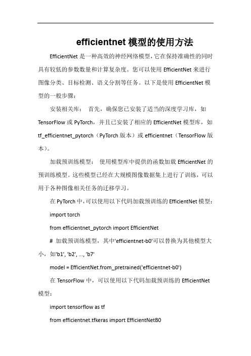
efficientnet模型的使用方法EfficientNet是一种高效的神经网络模型,它在保持准确性的同时具有较低的参数数量和计算复杂度。
您可以使用EfficientNet来进行图像分类、目标检测、语义分割等任务。
以下是使用EfficientNet模型的一般步骤:安装相关库:首先,确保您已安装了适当的深度学习库,如TensorFlow或PyTorch,并且已安装了相应的EfficientNet模型库,如tf_efficientnet_pytorch(PyTorch版本)或efficientnet(TensorFlow版本)。
加载预训练模型:使用模型库中提供的函数加载EfficientNet的预训练模型。
这些模型已经在大规模图像数据集上进行了训练,可以用于各种图像相关任务的迁移学习。
在PyTorch中,可以使用以下代码加载预训练的EfficientNet模型:import torchfrom efficientnet_pytorch import EfficientNet# 加载预训练模型,其中'efficientnet-b0'可以替换为其他模型大小,如'b1', 'b2', ..., 'b7'model = EfficientNet.from_pretrained('efficientnet-b0')在TensorFlow中,可以使用以下代码加载预训练的EfficientNet 模型:import tensorflow as tffrom efficientnet.tfkeras import EfficientNetB0# 加载预训练模型model = EfficientNetB0(weights='imagenet')适应您的数据:根据您的任务需求,修改模型的输出层,使其适应您的数据集和任务类型。
dpabinet手册

dpabinet手册
摘要:
1.dpabinet 手册简介
2.dpabinet 手册的主要内容
3.dpabinet 手册的使用方法
4.dpabinet 手册的优缺点分析
5.总结
正文:
dpabinet 手册是一本针对人工智能助手dpabinet 的使用指南,旨在帮助用户更好地理解和使用这一工具。
手册分为几个主要部分,包括dpabinet 的概述、功能介绍、使用方法和技巧以及常见问题的解答。
在概述部分,用户可以了解到dpabinet 的基本概念和主要功能;在功能介绍部分,手册详细列出了dpabinet 的各项功能,包括自然语言处理、图像识别、智能推荐等;在使用方法和技巧部分,手册提供了dpabinet 的具体操作步骤和示例,帮助用户快速上手;在常见问题解答部分,手册回答了用户在使用过程中可能遇到的问题,方便用户进行自我排查和解决。
dpabinet 手册的使用方法十分简单,用户只需根据自己的需求,按照手册中的步骤进行操作即可。
同时,手册也提供了在线帮助和客服支持,用户在遇到问题时可以随时寻求帮助。
总的来说,dpabinet 手册是一本实用、易懂的使用指南,无论是新手还
是老手,都可以从中获益。
然而,手册也存在一些不足,如部分内容的表述不够清晰,需要用户有一定的技术背景才能理解。
数字媒体应用技术专业《6.2创建和配置Avatar1》
3.激发学生的好奇心与求知欲,培养学生的团队合作精神。
重点难点
教学重点:
利用Mecanim动画系统创立和配置Avatar
教学难点:
熟练掌握利用Mecanim动画系统创立和配置Avatar
教学准备
参考教材、电子课件、电子教案、工作页
教学方法
1.采用讲授法、案例教学法、情景教学法、讨论法、观摩教学法、任务驱动式教学法;
2.学生通过案例操作,提高学生的学习兴趣与信心。
教学
环节
教学内容及过程
学生活动
新课
பைடு நூலகம்讲授
新课
讲授
Mecanim动画系统特别适合于人形角色动画的制作。人形骨架是在游戏中最昔遍采用的一种骨架结构,Unity为其提供了一个特别的工作流和一整套扩展的工具集。由于人形骨架结构的相似性,用户可以实现将动画效果从f人形骨架映射到另夕f人形骨架上去,从而实现动画重定向功能。除极少数情况之外,人形模型均具有相同的根本结构,即头部、躯干、四肢等。Mecanim正是充分利用了这一特点来简化了骨骼绑定和动画控制过程。创立动画的一个根本步骤就是建立一个从Mecanim系统的简化人形骨架结构到用户实际提供的骨架结构的映射,这种映射关系称为Avatar。
- 1、下载文档前请自行甄别文档内容的完整性,平台不提供额外的编辑、内容补充、找答案等附加服务。
- 2、"仅部分预览"的文档,不可在线预览部分如存在完整性等问题,可反馈申请退款(可完整预览的文档不适用该条件!)。
- 3、如文档侵犯您的权益,请联系客服反馈,我们会尽快为您处理(人工客服工作时间:9:00-18:30)。
2017 Temperature and Distortion Simulation for Laser Powder Bed Fusion PartsDivy Kishor TiwaryTechnical Specialist, Additive Solutions▸Originally CUBES, by Pan Computing LLC, Founded in 2012▸Physics based, multi-scale, process modeling software for thermomechanical processes(additive manufacturing, welding, thermalforming)▸Extensive model validation (Industrial Partners, America Makes, Penn State,Government)▸Acquired by Autodesk in March 2016▸Commercialized as Netfabb Simulation and integrated into Netfabb Thermo-Mechanical Simulation of Additive ManufacturingSimulation Utility for NetfabbBuild failure is a common problem in AMRecoater BladeInterferenceThermomechanical modeling can be used to avoid costly trial and error iterationsProcess ParametersFinal ProductHeat TransferTemperature HistoryDeformationMechanicalResponse Manual Optimization Iterations(will be automatic in the future)Inputs:-Machine process parameters-Material properties Outputs:-Deformation -Stress-TemperatureA Sequentially coupled thermomechanical model is used to calculate temperature, stress, & distortionHeat transfer:Mechanical response:Process ParametersHeat Transfer Temperature HistoryMechanical Response Stress & DeformationPart: 14 ft x 1.5 ft x 0.75 ftRun time: 1 day, 16 core machineThe Netfabb Sim solver uses custom Hex-8 ElementsProject PanAbaqusd dxkdT dx+Q =ρC pdT dt(1)T x,t =T 0+b T xt (2)k =k 0+b k T (3)C p =C 0+b C T(4)Q =ρC p b T x −b k b T 2t 2(5)q s =−k dTdxn=−kb T tn(6)Several key technologies were invented to facilitate the simulation of moving heat source problemsNovel fast and accurate Hex8 elements Layer by layer octree H-adaptivityCustom Finite Elements allow for run times over 1000x faster than general purpose solversLine where results are comparedAbaqus Netfabb ConvergedAbaqus Netfabb ConvergedAbaqus Netfabb ConvergedCoarser MeshRun-time for converged solution:•Abaqus: 208s•Netfabb Simulation: 0.23sThe modeling approach was successfully applied to simulate DED processesMoving source:▸Abaqus/ANSYS (4 elements / radius):▸9 billion nodes▸ 2 000 000 000 terabytes* of data for displacement results ▸Netfabb Simulation (1 element / radius):▸140 million nodes▸500 000 terabytes of dataSimulating Powder Bed Fusion parts adds computational challenge4 inches*10% of the whole internet, circa 2007Multi-scale modeling allows for fast simulation of entire partsDetailed fine-scale process parameter model (PRM) Input: Process parameters (Power, scan speed, layer thickness, etc.)Part-scale geometric model*Input: Geometry (STL)*4 hour runtime on a 14 core CPU PRM fileNetfabb Simulation is capable of analyzing full buildvolumesPart:275 mm x 204 mm x 44.1 mmRun time:11 hours20 core machineIn situ measurements give additional insight into the in-process physicsDVRTThermocoupleDAQThe measurements show the interaction of the individual deposition layersD i s p l a c e m e n t (m m )The model shows close agreement with experimental resultsPart-level simulation gives close agreement with post-process distortion measurementsExperimental data courtesy of America Makes, GE GRC, and United Technologies Research Center Part: 43 mm x 23 mm x 54 mmRun time: 30 min on 4 core machineThe simulations also predict common failure modesDIRECT MODELING OF POWDER LOSSES IMPROVES THE ACCURACY OF DISTORTION PREDICTIONSRESIDUAL STRESSES AND DISTORTION AFTER WIRE-CUTTING CAN BE ACCURATELY CALCULATEDWithout part scale plasticity With part scale plasticityExperimental data courtesy of America Makes, GE GRC, and United Technologies Research CenterThe distortion predictions can be used to output acompensated pre-formUnits in mmNominal Geometry Print Scan Nominal GeometrySimulation results Compensated GeometryExperimental data courtesy of America Makes, GE GRC, and United Technologies Research CenterCompensated Geometry Print ScanCompensation dramatically reduces distortion levels G4: Canonical 2With compensationWithout compensationLack of Fusion and Hot SpotsThermal images illustrate the temperature evolution during the buildMoving adaptivity can dramatically speed up simulations (thermal only)Run time: 3797 s Run time: 462 sPeak temperature can be tracked over all time steps on the refined meshThe simulation tracks the fraction of elements above or below threshold peak temperatures15.7 % of elements below 1250 o C:5.6 % of elements above 2600 o C:Multi-scale modeling can be used to predict defects on the entire buildMultiscale analysis to predict defects on the entire buildFraction below 1250 O C Fraction above 2600 O CCommercially Available as of v2018.1Conclusions1.The moving source model shows good agreement withexperimental in situ temperature and distortionmeasurements2.Results from small moving source analyses can bemapped onto larger geometries, allowing for fast andaccurate full part-scale simulations3.The simulated distortion predictions can be used topredict regions of likely recoater blade interference and support structure failure4.Direct modeling thermal losses to powder improves theaccuracy of the thermo-mechanical model5.Modeled distortion can be used to produce acompensated geometry, mitigating distortion prior to the first test buildAutodesk, Netfabb, and the Autodesk logo are registered trademarks or trademarks of Autodesk, Inc., and/or its subsidiaries and/or affiliates in the USA and/or other countries. All other brand names, product names, or trademarks belong to their respective holders. Autodesk reserves the right to alter product and services offerings, and specifications and pricing at any time without notice, and is not responsible for typographical or graphical errors that may appear in this document.© 2017 Autodesk. All rights reserved.。