GigaDevice发布GDF系列大容量以太网互联型M
200G光模块最全解析
200G光模块最全解析光模块市场正稳步向200G/400G发展,虚拟数据中心、物联网(IoT)和云计算不断普及,对更高带宽的需求推动了光模块市场的繁荣。
而今,200G/400G的光模块也已出现,并有望在未来几年继续保持良好的势头。
以下为您带来200G光模块最全解析。
下一代数据中心的主流:200G/400G数据中心光互连市场的主要转变是从10G到40G以及更高的40G到100G,另一个可预见的趋势是逐步淘汰核心网络和数据中心的低速光模块。
100G光器件的新发展为200G/400G光器件铺平了道路。
下一代数据中心在2018年底部署200G/400G以太网,并在2019或2020年成为主流。
总的来说,光模块市场正在向更高的速度,更低的功耗和更小的外形或尺寸发展。
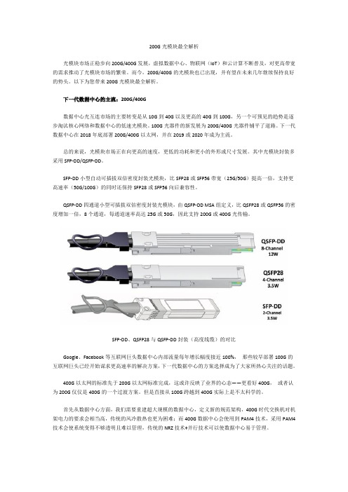
其中光模块封装多采用SFP-DD/QSFP-DD。
SFP-DD小型自动可插拔双倍密度封装光模块,比SFP28或SFP56带宽(25G/50G)提高一倍,支持更高速率(50G/100G)的同时还保持SFP28或SFP56向后兼容性。
QSFP-DD四通道小型可插拔双倍密度封装光模块,由QSFP-DD MSA组定义,比QSFP28或QSFP56的密度增加一倍,8个通道,每通道速率高达25G或50G,因此支持200G或400G光传输。
SFP-DD、QSFP28与QSFP-DD封装(高度线缆)的对比Google、Facebook等互联网巨头数据中心内部流量每年增长幅度接近100%,那些较早部署100G的互联网巨头已经开始谋求更高速率的解决方案,下一代数据中心的方案选择成为了大家所热心关注的话题。
400G以太网的标准先于200G以太网标准完成,这或许反映了业界的心态——更看好400G,或者认为200G仅仅是400G的一个过渡方案。
但是直接从100G跨越到400G实际上是不太科学的。
首先从数据中心方面,我们需要重建超大规模的数据中心,定义新的规范架构,400G时代交换机对机架电力的要求会相当高,传统的风冷散热也更为困难;而400G数据中心会使用到PAM4技术,采用PAM4技术会使系统变得不够透明且难以管理,传统的NRZ技术+并行技术可以使数据中心易于管理。
GigaDevice Semiconductor Inc. GD32 USBD固件库使用指南说明书
GigaDevice Semiconductor Inc. GD32 USBD固件库使用指南应用笔记AN049目录目录 (2)图索引 (4)表索引 (6)1.前言 (7)2.固件库说明 (8)2.1.main.c文件及函数说明 (9)2.1.1.时钟配置 (11)2.1.2.GPIO配置 (13)2.1.3.中断配置 (14)2.1.4.应用配置 (15)bd_driver底层文件及库函数说明 (16)3.应用类协议及例程说明 (18)3.1.HID (18)3.1.1.协议简介 (18)3.1.2.描述符解析 (18)3.1.3.应用类请求简介 (20)3.1.4.数据传输 (20)3.1.5.输出结果 (21)3.2.CDC (22)3.2.1.协议简介 (22)3.2.2.描述符解析 (22)3.2.3.应用类请求简介 (26)3.2.4.数据传输 (26)3.2.5.输出结果 (26)3.3.DFU (28)3.3.1.协议简介 (28)3.3.2.描述符解析 (28)3.3.3.应用类请求简介 (29)3.3.4.数据传输 (30)3.3.5.输出结果 (30)3.4.UAC (32)3.4.1.协议简介 (32)3.4.2.描述符解析 (32)3.4.3.应用类请求简介 (36)3.4.4.数据传输 (36)3.4.5.输出结果 (37)4.版本历史 (39)图索引图2-1. 固件库框架 (8)图2-2. USBD工程框架图 (9)图2-3. USBD时钟域 (11)图3-1. HID配置描述符 (18)图3-2. HID接口描述符 (19)图3-3. HID描述符 (19)图3-4. HID端点描述符 (19)图3-5. HID报文描述符 (20)图3-6. HID键盘应用示例 (21)图3-7. HID键盘打印 (21)图3-8. CDC配置描述符 (22)图3-9. CDC控制接口描述符 (23)图3-10. CDC标题描述符 (23)图3-11. CDC通话管理描述符 (23)图3-12. CDC抽象控制管理描述符 (24)图3-13. CDC联合功能描述符 (24)图3-14. CDC命令端点描述符 (24)图3-15. CDC数据接口描述符 (25)图3-16. CDC OUT描述符 (25)图3-17. CDC IN描述符 (25)图3-18. CDC设备枚举 (26)图3-19. 虚拟串口数据交互 (26)图3-20. 虚拟串口打印 (27)图3-21. DFU配置描述符 (28)图3-22. DFU接口描述符 (29)图3-23. DFU功能描述符 (29)图3-24. DFU设备枚举 (30)图3-25. DFU上位机 (31)图3-26. UAC配置描述符 (32)图3-27. UAC控制接口描述符 (32)图3-28. UAC 标题描述符 (33)图3-29. UAC输入终端描述符 (33)图3-30. UAC特性单元描述符 (34)图3-31. UAC输出终端描述符 (34)图3-32. UAC标准数据流零带宽接口描述符 (35)图3-33. UAC标准数据流接口描述符 (35)图3-34. UAC通用数据流描述符 (35)图3-35. UAC音频格式描述符 (35)图3-36. UAC标准端点描述符 (36)图3-37. UAC数据流端点描述符 (36)图3-38. UAC设备枚举 (37)图3-39. UAC声道配置 (37)图3-40. 音频播放 (38)表索引表1-1. USBD示例 (7)表1-2. 适用产品 (7)表2-1. Main函数 (9)表2-2. USBD系统时钟和分频 (11)表2-3. RCU配置代码 (11)表2-4. GPIO配置代码 (13)表2-5. 中断配置代码 (14)表2-6. 应用配置代码 (15)表2-7. 设备驱动层文件说明列表 (16)表2-8. usbd_core.h/c库函数说明列表 (16)表2-9. usbd_transc.c文件中的库函数说明列表 (16)表2-10. usbd_pwr.h/.c文件中的库函数说明列表 (17)表2-11. usbd_enum.h/.c文件中的库函数说明列表 (17)表3-1. HID部分设备部分应用类请求简介 (20)表3-2. CDC设备部分应用类请求简介 (26)表3-3. DFU设备应用类请求 (29)表3-4. DFU特定类请求的参数总结 (30)表3-5. UAC设备部分应用类请求简介 (36)表4-1. 版本历史 (39)1. 前言本文基于GD32 MCU产品的USBD模块,分析GD32 USBD固件库架构,简要描述了固件库函数的功能,通过具体的应用实例,阐明部分USBD设备类的实现过程,为用户的后续开发提供借鉴。
200G QSFP DD AOC在InfiniBand网络中的应用

200G QSFP DD AOC在InfiniBand网络中的应用随着数据中心的不断深入与高需求,人们对于此领域的拓展研究也在不断更迭最新技术与开发最优性能产品及解决方案。
前段时间易飞扬(Gigalight)发布了200G QSFP DD PSM8光模块,标志着基于NRZ调制的200G低成本数据中心内部平行光互连方案基本完成,也象征着公司在200G解决方案上的领先地位。
不同于业界主张的400G方案,易飞扬(Gigalight)坚持200G的数据中心解决方案,可为客户提供一站式的服务和解答。
本文主要根据现阶段超算中心的发展进程,来分析当前交换机之间InfiniBand技术的特征以及应用领域,其中以200G QSFP DD AOC为例,说明了超算中心互连技术的端口封装形式朝着更高工作带宽发展的现状。
超算系统里的InfiniBand技术根据2017年全球超级计算机500强榜单公布情况,我国无锡“神威--太湖之光”超级计算机以每秒125,435.9TFlop/s的峰值计算能力再次蝉联世界第一名,广州“天河二号”超算系统以每秒54,902.4TFlop/s的峰值计算能力位居世界第二名。
值得注意的是这些超算中心的交换互连技术均采用来自以色列InfiniBand的交换机和网络适配卡。
当前在超算中心互连技术阵营中有以色列的InfiniBand,高性能Ethernet,IBM的BlueGene,Cray和后起之秀Intel的OmniPath,这五大技术占据市场的重要份额,其中InfiniBand和高性能Ethernet占绝对领导地位。
超算中心的互连技术朝着更高带宽、更低延迟、更低功耗和更密的互联端口在发展,而InfiniBand互连技术在当前成为高性能存储互连方案的首选,正是因为其满足了大带宽和低时延的需求。
InfiniBand是一个统一的互连结构,既可以处理存储I/O、网络I/O,也能够处理进程间通信。
它可以将磁盘阵列、SANs、LANs、服务器和集群服务器进行互联,在相对短的距离内提供高带宽、低延迟的传输,而且在单个或多个互联网络中支持冗余的I/O通道,让数据中心在局部故障时仍能运转。
NSM-205GP 5-Port 无管理全吉比特以太网开关 功能说明书
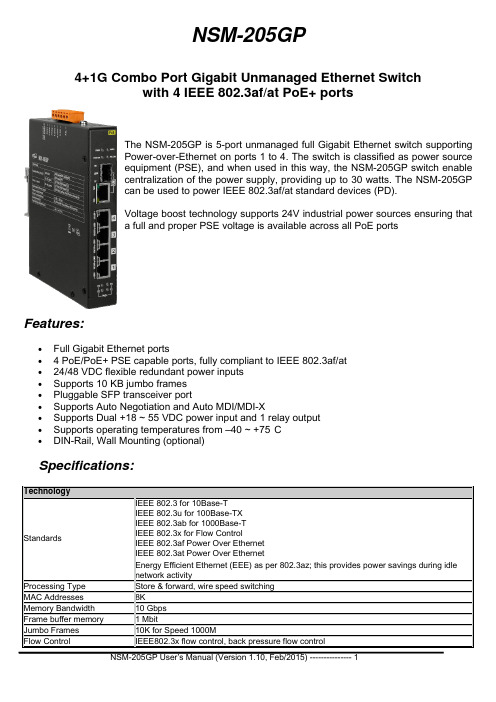
NSM-205GP4+1G Combo Port Gigabit Unmanaged Ethernet Switchwith 4 IEEE 802.3af/at PoE+ portsThe NSM-205GP is 5-port unmanaged full Gigabit Ethernet switch supportingPower-over-Ethernet on ports 1 to 4. The switch is classified as power sourceequipment (PSE), and when used in this way, the NSM-205GP switch enablecentralization of the power supply, providing up to 30 watts. The NSM-205GPcan be used to power IEEE 802.3af/at standard devices (PD).Voltage boost technology supports 24V industrial power sources ensuring thata full and proper PSE voltage is available across all PoE portsFeatures:∙Full Gigabit Ethernet ports∙ 4 PoE/PoE+ PSE capable ports, fully compliant to IEEE 802.3af/at∙24/48 VDC flexible redundant power inputs∙Supports 10 KB jumbo frames∙Pluggable SFP transceiver port∙Supports Auto Negotiation and Auto MDI/MDI-X∙Supports Dual +18 ~ 55 VDC power input and 1 relay output∙Supports operating temperatures from –40 ~ +75°C∙DIN-Rail, Wall Mounting (optional)Specifications:TechnologyStandards IEEE 802.3 for 10Base-TIEEE 802.3u for 100Base-TXIEEE 802.3ab for 1000Base-TIEEE 802.3x for Flow ControlIEEE 802.3af Power Over EthernetIEEE 802.3at Power Over EthernetEnergy Efficient Ethernet (EEE) as per 802.3az; this provides power savings during idle network activityProcessing Type Store & forward, wire speed switchingMAC Addresses 8KMemory Bandwidth 10 GbpsFrame buffer memory 1 MbitJumbo Frames 10K for Speed 1000MFlow Control IEEE802.3x flow control, back pressure flow controlInterfaceRJ-45 Ports 10/100/1000 BaseT(X), 10/100BaseT(X) auto negotiation speed, full/half duplex mode, and auto MDI/MDI-X connectionFiber Port 1000BaseSFP slot/100BaseSFP slotLED Indicators PWR1, PWR2, Power fail, 10/100M, 1000M, Link/Act, Power Device is detected Ethernet Isolation 1500 Vrms 1 minuteDIP Switch 100BaseSFP/1000BaseSFP and PoE/PoE+ settingPower InputRedundant Input Range Flexible input +24/+48 VDC Nominal. ( +18 ~ +55 VDC)Power Consumption 0.13@ 48 VDC without PD loading; 3.1 A @ 48 VDC with PD full loading (30 W per ports) 0.25@ 24 VDC without PD loading; 6.2 A @ 24 VDC with PD full loading (30 W per ports)Alarm Contact One relay output with current carrying capacity of 1A @ 30 VDC Protection Power reverse polarity protectionConnector 6-Pin Removable Terminal Block (Power & Relay)MechanicalChassis Metal with an IP30 ingress protection ratingDimensions (W x L x H) 28 mm x 160 mm x 122 mmInstallation DIN-Rail or Wall Mounting (with optional kit)EnvironmentalOperating Temperature -40 °C ~ + 75 °C ( -40° F to 167° F )Storage Temperature -40 °C ~ + 85 °C (-40 F to 185° F)Ambient Relative Humidity 10 ~ 90% RH, non-condensingGetting to know your NSM-205GP SwitchPackage Contents:· NSM-205GP· DIN-Rail mounting (pre-installed on the unit)· This manualNote – optional wall mounting kits may be orderedLED Indicator Functions:LED Color DescriptionEthernet Port (P1 ~ P4) Green On Link/Act to 1000 Mbps Yellow On Link/Act to 10/100 Mbps Red On Power Device is detectedCombo Port (P5) Green On Link/ActPWR1 Yellow On This yellow LED is turned on when power is applied to the PWR1 input PWR2 Yellow On This yellow LED is turned on when power is applied to the PWR2 inputPower fail Red On Power is not being supplied to power input PWR1 and PWR2 Red Off Power is being supplied to power input PWR1 and PWR2Redundant Power Input:Both power inputs can be connected simultaneously to live DC power sources. If one power source fails, the other live source will act as a backup, and automatically supplies all of NSM-205GP power needs.External power supply is connected using the removable terminal block:PWR (Power) : Power input (+18 ~ +55 VDC) and should be connected to the power supply (+) GND: Ground and should be connected to the power supply (-)Accessories:DR-120-48 48 V/2.5 A, 120 W Single Output Industrial DIN Rail Power SupplyMDR-60-48 48 V/1.25 A, 60 W Single Output Industrial DIN Rail Power SupplyDR-120-24 24V/5 A, 120 W Single Output Industrial DIN Rail Power SupplySDR-240-24 24 V/10 A, 240 W Single Output Industrial DIN Rail Power Supply with PFCFunctionPoE Ethernet Port Connection:PoE ports located on the NSM-205GP’s front panel are used to connect to PoE-enabled devices. The pinout follows the Alternative A, MDI mode” of 802.3af/802.3at standards. Please see the details in the following table.Pin Signal (MDI Port Pinouts) PoE1 BI_DA+ V+2 BI_DA- V+3 BI_DB+ V-4 BI_DC+ --5 BI_DC- --6 BI_DB- V-7 BI_DD+ --8 BI_DD+ --DIP Switch Settings:DIP Switch Setting DescriptionSFP Speed ON 100BaseSFPOFF 1000BaseSFP(default)PoE AF/AT ON PoE(default)OFF PoE+To actively update DIP switch settings, power off and then power on the NSM-205GP.Dimensions (unit = mm):Accessories:nm, 0.5 km SFP module850SFP-1G85M-SX Multi-mode1310 nm, 2 km SFP module SFP-1G13M-SX2 Multi-modeSFP-1G13S-LX Single-mode 1310 nm, 10 km SFP module SFP-1G13S-LX20 Single-mode 1310 nm, 20 km SFP module SFP-1G13S-LHX Single-mode 1310 nm, 40 km SFP module SFP-1G15S-XD Single-mode 1550 nm, 60 km SFP module。
GigaDevice发布多款GDF和GDF系列大容量增强
GigaDevice发布多款GDF和GDF系列大容量增强型MCUGigaDevice发布多款GD32F103和GD32F101系列大容量增强型MCU业界领先的半导体供应商GigaDevice (兆易创新)日前在北京发布基于108MHz ARM Cortex-M3内核的多款大容量增强型GD32F103和GD32F101系列微控制器新品。
目前,该系列产品已经开始提供样片并将于下月正式投入量产。
新发布的GD32F103/GD32F101系列大容量增强型MCU片上闪存容量从256KB起最大可至3072KB,这也是迄今为止业界最大容量的Cortex-M3内核通用微控制器。
高性能高可靠性的片上Flash可重复擦写100000次,保存数据超过20年。
CPU访问闪存及执行代码高速零等待,执行效率比市场同类产品提高30%-40%,在最高主频下的处理性能可达110DMIPS。
RAM容量从32KB到96KB,封装有LQFP64、LQFP100及LQFP144等多种选择,所有GD32系列MCU在软件和引脚封装方面相互兼容,为系统开发与升级提供极佳的灵活性和极具竞争力的性价比。
GD32F103/GD32F101系列大容量增强型MCU延续了已有产品的性能和效能优势,并进一步丰富了高性能的外设组合,可以在同时需要USB2.0 FS、CAN、I2S和内存卡SDIO接口的产品设计中发挥工业标准的32位MCU的卓越性能,并整合了多达14个定时器及5个UART、3个SPI、2个I2C接口。
另外,新增的模拟外设包括2个12位的DAC及多达3个采样率为1MSPS的12位高速ADC,2个I2S接口可实现音频解码和输出,8/16位外部总线接口(EXMC)还可支持SRAM、NOR Flash、NAND Flash等多种静态存储器扩展,加强了对设备互连及控制应用的支持,满足信息传输及人机接口等多种标准连接功能的需求。
创新的GD32系列MCU在遵循行业安全标准的基础上,增强了存储器保护单元(MPU)和时钟安全系统(CSS),能够安全执行软件代码及数据,内置的循环冗余校验(CRC)功能可检查传输及存储数据的完整性。
GD32 MCU Tools Introduction (Apr 2014)
8
GD32F150R-EVAL 超值系列评估板
基于GD32F150R8T6的USB超值型评估板,所有的 I/O端口和外设都已引出,可完整全面的评估GD32 系列超值型产品的性能与集成外设,包括: SWD、 RTC、I2C、USART、I2S、SPI、ADC、DAC、 USB 2.0 FS、HDMI-CEC、CMP、TSI。 GD32F150R8T6评估板外扩展2.2” TFT LCD显示屏 (可选),并配备滑动条以评估触摸感测接口(TSI) 可通过第三方仿真器在此板上调试软件,支持2线 SWD接口,并支持串口ISP下载程序。 通过USB供电。
产品型号 GD32150R-EVAL GD32150R-EVAL/1 (不含LCD)
参考售价 RMB 170 RMB 125
9
GD32103B-START 入门级评估板
基于GD32F103VBT6的入门级评估板,所有管脚 均 已引出。板上提供了常用接口,包括:JTAG、 BOOT、LED、Button Key、USB Device。
参考售价 RMB 295 RMB 220
产品型号 GD32103B-EVAL GD32103B-EVAL/1 (不含LCD)
GD32103C-EVAL评估板
基于GD32F103VCT6的增强型评估板,所有的I/O端 口和外设都已引出,可完整全面的评估GD32系列 MCU产品性能与集成外设,包括:JTAG、BOOT、 RTC、CAN、I2C、I2S、USART、SDIO、EXMC、 SPI、ADC、DAC、USB 2.0 FS。 GD32F103VCT6评估板外扩NAND和3.2” TFT LCD触 摸屏(可选),可体验和评估GD32系列MCU的外部总线 扩展(EXMC)功能。 可通过第三方仿真器在此板上调试软件,支持2线 SWD及标准JTAG下载接口,并支持串口ISP下载程序。 通过USB或AC-DC供电。
极限交换机VDX6740和VDX6740T产品介绍说明书
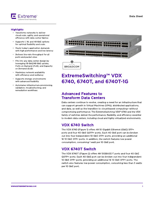
The VDX 674 0 T-1G ( Fig ure 3) offers 4 8 10 0 0 BA SE-T p ort s and t w o 4 0 Gb E QSFP+ p ort s. Each 4 0 Gb E p ort can b e b roken out int o four ind ep end ent 10 Gb E SFP+ p ort s, p rovid ing an ad d it ional eig ht 10 Gb E SFP+ p ort s for up link. A ll 4 8 10 0 0 BA SE-T p ort s can b e up g rad ed t o 4 8 10 GBA SE-T p ort s via t he Cap acit y on Dem and (CoD) soft w are license. Tw o 4 0 Gb E p ort s are enab led as p art of t he b ase license. The ad d it ional t w o 4 0 Gb E p ort s can b e up g rad ed via t he Port s on Dem and ( PoD) soft w are license.
- Meet s t od ay?s ap p licat ion d em and s w it h high perform ance and low latency
- Delivers line-rate t hroughput for all p ort s and p acket sizes
Dat a Sheet
SIMATIC S7-1500 ET 200MP 自动化系统 系统手册说明书

SIMATICS7-1500/ET 200MP 自动化系统系统手册01/2023A5E03461186-AKSiemens AG Digital Industries Postfach 48 48 90026 NÜRNBERG 德国Ⓟ 02/2023 本公司保留更改的权利Copyright © Siemens AG 2013 - 2023.保留所有权利法律资讯警告提示系统为了您的人身安全以及避免财产损失,必须注意本手册中的提示。
人身安全的提示用一个警告三角表示,仅与财产损失有关的提示不带警告三角。
警告提示根据危险等级由高到低如下表示。
危险表示如果不采取相应的小心措施,将会导致死亡或者严重的人身伤害。
警告表示如果不采取相应的小心措施,可能导致死亡或者严重的人身伤害。
小心表示如果不采取相应的小心措施,可能导致轻微的人身伤害。
注意表示如果不采取相应的小心措施,可能导致财产损失。
当出现多个危险等级的情况下,每次总是使用最高等级的警告提示。
如果在某个警告提示中带有警告可能导致人身伤害的警告三角,则可能在该警告提示中另外还附带有可能导致财产损失的警告。
合格的专业人员本文件所属的产品/系统只允许由符合各项工作要求的合格人员进行操作。
其操作必须遵照各自附带的文件说明,特别是其中的安全及警告提示。
由于具备相关培训及经验,合格人员可以察觉本产品/系统的风险,并避免可能的危险。
按规定使用 Siemens 产品请注意下列说明:警告Siemens 产品只允许用于目录和相关技术文件中规定的使用情况。
如果要使用其他公司的产品和组件,必须得到 Siemens 推荐和允许。
正确的运输、储存、组装、装配、安装、调试、操作和维护是产品安全、正常运行的前提。
必须保证允许的环境条件。
必须注意相关文件中的提示。
商标所有带有标记符号 ® 的都是 Siemens AG 的注册商标。
本印刷品中的其他符号可能是一些其他商标。
希尔施曼 GRS1030-16T9SMMV9HHSE2S04.1 工业以太网交换机数据表说明书
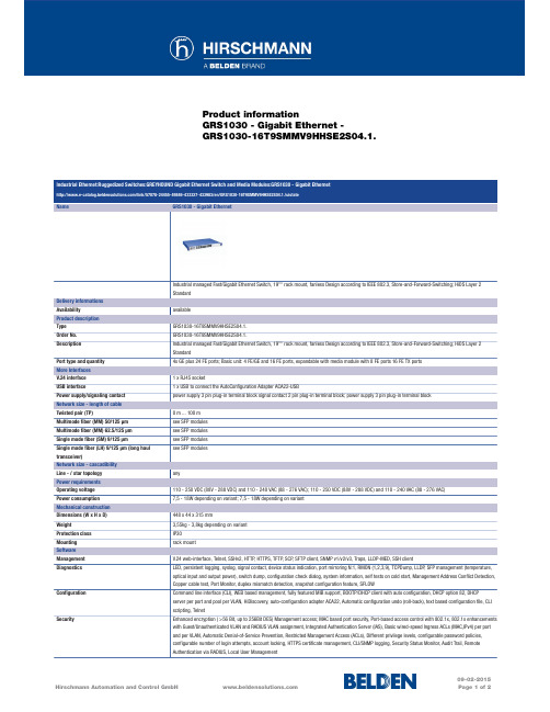
Product informationGRS1030 - Gigabit Ethernet -GRS1030-16T9SMMV9HHSE2S04.1.Industrial Ethernet:Ruggedized Switches:GREYHOUND Gigabit Ethernet Switch and Media Modules:GRS1030 - Gigabit Ethernet/link/57078-24455-49846-433327-433983/en/GRS1030-16T9SMMV9HHSE2S04.1./uistateName GRS1030 - Gigabit EthernetIndustrial managed Fast/Gigabit Ethernet Switch, 19"" rack mount, fanless Design according to IEEE 802.3, Store-and-Forward-Switching; HiOS Layer 2StandardDelivery informationsAvailability availableProduct descriptionType GRS1030-16T9SMMV9HHSE2S04.1.Order No.GRS1030-16T9SMMV9HHSE2S04.1.Description Industrial managed Fast/Gigabit Ethernet Switch, 19"" rack mount, fanless Design according to IEEE 802.3, Store-and-Forward-Switching; HiOS Layer 2StandardPort type and quantity4x GE plus 24 FE ports; Basic unit: 4 FE/GE and 16 FE ports, expandable with media module with 8 FE ports 16 FE TX portsMore InterfacesV.24 interface 1 x RJ45 socketUSB interface 1 x USB to connect the AutoConfiguration Adapter ACA22-USBPower supply/signaling contact power supply 3 pin plug-in terminal block signal contact 2 pin plug-in terminal block; power supply 3 pin plug-in terminal blockNetwork size - length of cableTwisted pair (TP)0 m ... 100 mMultimode fiber (MM) 50/125 µm see SFP modulesMultimode fiber (MM) 62.5/125 µm see SFP modulesSingle mode fiber (SM) 9/125 µm see SFP modulesSingle mode fiber (LH) 9/125 µm (long haulsee SFP modulestransceiver)Network size - cascadibilityLine - / star topology anyPower requirementsOperating voltage110 - 250 VDC (88V - 288 VDC) and 110 - 240 VAC (88 - 276 VAC); 110 - 250 VDC (88V - 288 VDC) and 110 - 240 VAC (88 - 276 VAC)Power consumption7,5 - 18W depending on variant; 7,5 - 18W depending on variantMechanical constructionDimensions (W x H x D)448 x 44 x 315 mmWeight3,55kg - 3,8kg depending on variantProtection class IP30Mounting rack mountSoftwareManagement V.24 web-interface, Telnet, SSHv2, HTTP, HTTPS, TFTP, SCP, SFTP client, SNMP v1/v2/v3, Traps, LLDP-MED, SSH clientDiagnostics LED, persistent logging, syslog, signal contact, device status indication, port mirroring N:1, RMON (1,2,3,9), TCPDump, LLDP, SFP management (temperature,optical input and output power), switch dump, configuration check dialog, system information, self tests on cold start, Management Address Conflict Detection,Copper cable test, Port Monitor, duplex mismatch detection, snapshot configuration feature, SFLOWConfiguration Command line interface (CLI), WEB based management, fully featured MIB support, BOOTP/DHCP client with auto configuration, DHCP option 82, DHCPserver per port and pool per VLAN, HiDiscovery, auto-configuration adapter ACA22, Automatic configuration undo (roll-back), text based configuration file, CLIscripting, TelnetSecurity Enhanced encryption ( >56 Bit, up to 256Bit DES) Management access; MAC based port security, Port-based access control with 802.1x, 802.1x enhancementswith Guest/Unauthenticated VLAN and RADIUS VLAN assignment, Integrated Authentication Server (IAS), Basic wired-speed Ingress ACLs (MAC,IPv4) per portand per VLAN, Automatic Denial-of-Service Prevention, Restricted Management Access (ACLs), Different privilege levels, configurable password policies,configurable number of login attempts, account locking, HTTPS certificate management, CLI/SNMP logging, Security Status Monitor, Audit Trail, RemoteAuthentication via RADIUS, Local User ManagementFor more information please contact:Hirschmann Automation and Control GmbHStuttgarter Strasse 45-5172654 NeckartenzlingenGermanyPhone: +49 7127/14-1809E-Mail:*********************The information published in the websites has been compiled as carefully as possible. It is subject to alteration without notice in technical as well as in price-related/commercial respect. The complete information and data were available on user documentation. Mandatory information can only be obtained by a concrete query.。
Gigabit Ethernet

众所周知,当前Gigabit Ethernet(千兆以太网)已经将Ethernet世界带入新的纪元,它是下个世纪延伸以太局域网络技术的最佳解决方案。
因为在经济成本的原则下,Gigabit Ethernet 不但能够满足消耗大量网络带宽的应用软件的需要,而且由于使用原有Ethernet的架构为基础,不必更换正在使用的网络和操作系统,因此用户无须放弃旧的Ethernet标准和使用习惯,这在技术转移的层面上极受青睐。
目前,很多主板生产商都将千兆网络传输界面正式纳入到产品标准中,使普通用户也能享受到高速的网络传输功能。
趁着这股Gigabit Ethernet热潮的兴起,下面笔者就为大家介绍一下市面上主流的各种GigaLAN网络控制芯片的技术特点和功能,并对各种网络芯片的传输速度进行对比测试,供各位感兴趣的朋友作一参考。
一、Gigabit Ethernet的由来早在1996年6月快速以太网Fast Ethernet标准(802 3u)获得认证之后,IEEE组织便着手定义1 Gbps Ethernet标准(802 3z)的工作。
正如Fast Ethernet一样,Gigabit Ethernet技术在局域网络工业界大受瞩目,并旋即于1996年6月成立一个由八十多家公司组成的GEA联盟(GigabitEthernet Alliance)。
GEA的任务在于协助802.3z工作小组制定标准,并指导世人Gigabit Ethernet的应用,以及制定客户产品之间的互通性标准。
Gigabit Ethernet打着高出Fast Ethernet数十倍速度的旗号来拓展现有的网络带宽,但是目前到底谁真正用得上1Gbps的网络传输速度呢?因为用户才将网络升级到Fast Ethernet(用于服务器或网络骨干的连接)不久。
而FDDI界面于标准认可的六年后,就在网络骨干和服务器连接领域占有七成的市场。
对Gigabit Ethernet而言,业界无法说服用户从Fast Ethernet升级纯粹只是为了更佳的性能改善。
DPtech FW1000系列应用防火墙安装手册v2.01

由于产品版本升级或其他原因,本手册内容有可能变更。杭州迪普科技 有限公司保留在没有任何通知或者提示的情况下对本手册的内容进行修 改的权利。本手册仅作为使用指导,杭州迪普科技有限公司尽全力在本 手册中提供准确的信息,但是杭州迪普科技有限公司并不确保手册内容 完全没有错误,本手册中的所有陈述、信息和建议也不构成任何明示或 暗示的担保。
iv
DPtech FW1000 系列应用防火墙安装手册
2.2.4 抗干扰要求............................................................................................................................... 3 2.2.5 防雷击要求............................................................................................................................... 3 2.2.6 接地要求................................................................................................................................... 3 2.2.7 布线要求................................................................................................................................... 3 2.3 安装工具......................................................................................................................................4
Prosoft MVI56-MCM ControlLogix 平台 Modbus 通讯模块 说明书

2.9.2.1 功能 5.................................................................................................... 16 2.9.2.2 功能 6 和 16.......................................................................................... 16 2.9.2.3 功能 15.................................................................................................. 17 MVI56-MCM模块和ControlLogix处理器之间的数据流.......................................... 18 2.9.3 从站驱动................................................................................................... 18 2.9.4 主站驱动模式........................................................................................... 20 2.9.4.1 主站命令列表....................................................................................... 21 3 修改模块设置........................................................................................................... 23 3.1 上电................................................................................................................... 23 3.2 运行中更改参数............................................................................................... 23 3.3 装配模块........................................................................................................... 23 3.4 模块数据对象 (MCMModuleDef)................................................................... 29 3.4.1 设置对象................................................................................................... 30 3.4.1.1 数据传输参数 (MCMModule)............................................................. 31
以太网的标准
4.1 业务节点接口 4.1.1 1000BASE-LX/100BASE-FX 接口
1000BASE-LX/100BASE-FX接口的测试方法见YD/T XXXX-2001《高端路由器设备检验方法》。 4.1.2 ATM 接口
ATM 155 520kbit/s电接口、155 520kbit/s光接口、622 080kbit/s光接口的测试方法见YD/T XXXX-2001《高端路由器设备检验方法》。 4.1.3 POS 接口
3 基于以太网技术的宽带接入网网络结构
1
×× ××××—×××× 基于以太网技术的宽带接入网网络结构见图1 。
管理网
A
核心网 社区服务器
计算机 1
局
用
侧
户
计算机 n
设
侧
备
设
用户驻地网 1
备
用户驻地网 n
SNI 基于以太网技术的宽带接入系统 UNI
图1 基于以太网技术的宽带接入网网络结构图 基于以太网技术的宽带接入系统由局侧设备和用户侧设备组成。在面向小区或商业用户的应用中, 局侧设备一般考虑放在小区内,用户侧设备一般位于居民楼内;或者局侧设备位于商业大楼内,而用户 侧设备位于楼层内。而对于其它区域密集型用户的接入,局侧设备和用户侧设备的放置根据具体情况而 定。 局侧设备与用户侧设备推荐采用星型拓扑,局侧设备与核心网设备之间的拓扑结构可以是星型,也 可以是环型。 局侧设备和用户侧设备的技术要求见YD/T 1160-2001。
gbt1762621999电磁兼容试验和测量技术静电放电抗扰度试验gbt1762631998电磁兼容试验和测量技术射频电磁场辐射抗扰度试验gbt1762641998电磁兼容试验和测量技术电快速瞬变脉冲群扰度试验gbt1762651999电磁兼容试验和测量技术浪涌冲击抗扰度试验gbt1762661998电磁兼容试验和测量技术射频场感应的传导骚扰抗扰度试验gbt1762681998电磁兼容试验和测量技术工频磁场扰度试验gb92541998信息技术设备的无线电骚扰限值和测量方法ydt11562001路由器测试规范高端路由器ydt11602001接入网技术要求基于以太网技术的宽带接入网rfc0791091981网间网协议iprfc0792091981互联网控制消息协议icmprfc0826111982以太网地址解析协议arprfc1075111988距离向量组播路由协议dvmrprfc1271111991远程网络监视管理信息库rfc1661071994点到点协议ppprfc2131031997动态主机配置协议dhcprfc2236111997网间网组管理协议igmprfc2328041998开放最短路径优先ospfv2rfc2362061998与协议无关的组播pimsmrfc2453111998路由信息协议ripv2rfc2865062000拨号用户的远程认证服务radiusrfc2866062000radius计费基于以太网技术的宽带接入网网络结构图基于以太网技术的宽带接入系统由局侧设备和用户侧设备组成
DDN大容量存储平台解决方案

DDN大容量存储平台解决方案目录一、内容描述 (3)1.1 背景与挑战 (3)1.2 DDN品牌介绍 (4)1.3 解决方案概述 (5)二、DDN大容量存储平台产品概述 (7)2.1 产品特点 (8)2.1.1 高性能 (9)2.1.2 高可靠性 (10)2.1.3 高扩展性 (11)2.2 产品系列 (13)2.2.1 家庭存储系列 (14)2.2.2 企业级存储系列 (15)2.2.3 数据中心存储系列 (17)三、DDN大容量存储平台解决方案架构 (18)3.1 系统架构 (19)3.1.1 前端访问层 (21)3.1.2 应用服务层 (22)3.1.3 存储管理层 (23)3.2 数据流处理 (24)3.2.1 数据上传 (25)3.2.2 数据存储 (26)3.2.3 数据下载 (27)四、DDN大容量存储平台安装与配置 (29)4.1 安装步骤 (30)4.1.1 硬件安装 (31)4.1.2 软件安装 (32)4.2 配置过程 (32)4.2.1 创建存储池 (33)4.2.2 分配存储空间 (35)4.2.3 设置访问权限 (36)五、DDN大容量存储平台管理 (37)5.1 用户管理 (39)5.1.1 用户账户创建 (40)5.1.2 用户权限分配 (41)5.2 数据管理 (42)5.2.1 数据备份 (43)5.2.2 数据恢复 (44)5.2.3 数据迁移 (45)5.3 性能优化 (46)5.3.1 调整存储策略 (48)5.3.2 优化数据传输路径 (49)六、DDN大容量存储平台应用案例 (50)6.1 家庭用户案例 (52)6.2 企业用户案例 (53)6.3 教育行业案例 (54)6.4 医疗行业案例 (55)七、DDN大容量存储平台技术支持与服务 (57)7.1 技术支持 (58)7.1.1 技术咨询 (60)7.1.2 技术培训 (61)7.2 售后服务 (61)7.2.1 硬件保修 (62)7.2.2 软件更新 (63)八、总结与展望 (64)8.1 解决方案总结 (66)8.2 发展前景展望 (67)一、内容描述DDN大容量存储平台解决方案是一种创新的数据管理方案,旨在满足现代企业对于数据存储和访问速度的高要求。
莫贾5G无管理以太网开关 EDS-G205 系列产品特性与优势说明书
EDS-G205Series5G-port full Gigabit unmanaged Ethernet switchesFeatures and Benefits•Fiber-optic options for extending distance and improving electrical noiseimmunity•Redundant dual12/24/48VDC power inputs•Supports10KB jumbo frames•Relay output warning for power failure and port break alarm•Broadcast storm protection•-40to75°C wide operating temperature range(-T models)CertificationsIntroductionThe EDS-G205-1GTXSFP switches are equipped with5Gigabit Ethernet ports and1fiber-optic port,making them ideal for applications that require high bandwidth.The EDS-G205-1GTXSFP switches provide an economical solution for your industrial Gigabit Ethernet connections,and the built-in relay warning function alerts network managers when power failures or port breaks occur.The4-pin DIP switches can be used for controlling broadcast protection,jumbo frames,and IEEE802.3az energy saving.In addition,100/1000SFP speed switching is ideal for easy on-site configuration for any industrial automation application.A standard-temperature model,which has an operating temperature range of-10to60°C,and a wide-temperature range model,which has an operating temperature range of-40to75°C,are available.Both models undergo a100%burn-in test to ensure that they fulfill the special needs of industrial automation control applications.The switches can be installed easily on a DIN rail or in distribution boxes.SpecificationsInput/Output InterfaceAlarm Contact Channels1relay output with current carrying capacity of1A@24VDCEthernet Interface10/100/1000BaseT(X)Ports(RJ45connector)4Auto negotiation speedFull/Half duplex modeAuto MDI/MDI-X connection1Combo Ports(10/100/1000BaseT(X)or100/1000BaseSFP+)Standards IEEE802.3for10BaseTIEEE802.3ab for1000BaseT(X)IEEE802.3u for100BaseT(X)and100BaseFXIEEE802.3x for flow controlIEEE802.3z for1000BaseXIEEE802.3az for Energy-Efficient EthernetSwitch PropertiesMAC Table Size8KPacket Buffer Size1MbitsJumbo Frame Size10KBProcessing Type Store and ForwardDIP Switch ConfigurationEthernet Interface Broadcast storm protectionJumbo FrameIEEE802.3az energy saving100/1000SFP speed switchingPort break alarmPower ParametersConnection1removable6-contact terminal block(s)Input Voltage12/24/48VDCRedundant dual inputsOperating Voltage9.6to60VDCReverse Polarity Protection SupportedInput Current380mAPhysical CharacteristicsHousing MetalIP Rating IP30Dimensions29x135x105mm(1.14x5.31x4.13in)Weight290g(0.64lb)Installation DIN-rail mountingWall mounting(with optional kit) Environmental LimitsOperating Temperature EDS-G205-1GTXSFP:-10to60°C(14to140°F)EDS-G205-1GTXSFP-T:-40to75°C(-40to167°F) Storage Temperature(package included)-40to85°C(-40to185°F)Ambient Relative Humidity5to95%(non-condensing)Standards and CertificationsFreefall IEC60068-2-32EMC EN55032/24EMI CISPR32,FCC Part15B Class AEMS IEC61000-4-2ESD:Contact:6kV;Air:8kVIEC61000-4-3RS:80MHz to1GHz:20V/mIEC61000-4-4EFT:Power:2kV;Signal:2kVIEC61000-4-5Surge:Power:2kV;Signal:2kVIEC61000-4-6CS:10VIEC61000-4-8PFMFHazardous Locations ATEXClass I Division2Maritime ABSLRNKDNVRailway EN50121-4Safety EN60950-1UL508EN60950-1(LVD)Shock IEC60068-2-27Vibration IEC60068-2-6MTBFTime2,823,446hrsStandards Telcordia(Bellcore),GBWarrantyWarranty Period5yearsDetails See /warrantyPackage ContentsDevice1x EDS-G205Series switchInstallation Kit1x cap,plastic,for SFP slotDocumentation1x quick installation guide1x warranty cardNote SFP modules need to be purchased separately for use with this product. DimensionsOrdering InformationEDS-G205-1GTXSFP41-10to60°CEDS-G205-1GTXSFP-T41-40to75°C Accessories(sold separately)SFP ModulesSFP-1FELLC-T SFP module with1100Base single-mode with LC connector for80km transmission,-40to85°Coperating temperatureSFP-1FEMLC-T SFP module with1100Base multi-mode,LC connector for2/4km transmission,-40to85°C operatingtemperatureSFP-1FESLC-T SFP module with1100Base single-mode with LC connector for40km transmission,-40to85°Coperating temperatureSFP-1G10ALC WDM-type(BiDi)SFP module with11000BaseSFP port with LC connector for10km transmission;TX1310nm,RX1550nm,0to60°C operating temperatureSFP-1G10ALC-T WDM-type(BiDi)SFP module with11000BaseSFP port with LC connector for10km transmission;TX1310nm,RX1550nm,-40to85°C operating temperatureSFP-1G10BLC WDM-type(BiDi)SFP module with11000BaseSFP port with LC connector for10km transmission;TX1550nm,RX1310nm,0to60°C operating temperatureSFP-1G10BLC-T WDM-type(BiDi)SFP module with11000BaseSFP port with LC connector for10km transmission;TX1550nm,RX1310nm,-40to85°C operating temperatureSFP-1G20ALC WDM-type(BiDi)SFP module with11000BaseSFP port with LC connector for20km transmission;TX1310nm,RX1550nm,0to60°C operating temperatureSFP-1G20ALC-T WDM-type(BiDi)SFP module with11000BaseSFP port with LC connector for20km transmission;TX1310nm,RX1550nm,-40to85°C operating temperatureSFP-1G20BLC WDM-type(BiDi)SFP module with11000BaseSFP port with LC connector for20km transmission;TX1550nm,RX1310nm,0to60°C operating temperatureSFP-1G20BLC-T WDM-type(BiDi)SFP module with11000BaseSFP port with LC connector for20km transmission;TX1550nm,RX1310nm,-40to85°C operating temperatureSFP-1G40ALC WDM-type(BiDi)SFP module with11000BaseSFP port with LC connector for40km transmission;TX1310nm,RX1550nm,0to60°C operating temperatureSFP-1G40ALC-T WDM-type(BiDi)SFP module with11000BaseSFP port with LC connector for40km transmission;TX1310nm,RX1550nm,-40to85°C operating temperatureSFP-1G40BLC WDM-type(BiDi)SFP module with11000BaseSFP port with LC connector for40km transmission;TX1550nm,RX1310nm,0to60°C operating temperatureSFP-1G40BLC-T WDM-type(BiDi)SFP module with11000BaseSFP port with LC connector for40km transmission;TX1550nm,RX1310nm,-40to85°C operating temperatureSFP-1GEZXLC SFP module with11000BaseEZX port with LC connector for110km transmission,0to60°C operatingtemperatureSFP-1GEZXLC-120SFP module with11000BaseEZX port with LC connector for120km transmission,0to60°C operatingtemperatureSFP-1GLHLC SFP module with11000BaseLH port with LC connector for30km transmission,0to60°C operatingtemperatureSFP-1GLHLC-T SFP module with11000BaseLH port with LC connector for30km transmission,-40to85°C operatingtemperatureSFP-1GLHXLC SFP module with11000BaseLHX port with LC connector for40km transmission,0to60°C operatingtemperatureSFP-1GLHXLC-T SFP module with11000BaseLHX port with LC connector for40km transmission,-40to85°Coperating temperatureSFP-1GLSXLC SFP module with11000BaseLSX port with LC connector for1km/2km transmission,0to60°Coperating temperatureSFP-1GLSXLC-T SFP module with11000BaseLSX port with LC connector for1km/2km transmission,-40to85°Coperating temperatureSFP-1GLXLC SFP module with11000BaseLX port with LC connector for10km transmission,0to60°C operatingtemperatureSFP-1GLXLC-T SFP module with11000BaseLX port with LC connector for10km transmission,-40to85°C operatingtemperatureSFP-1GSXLC SFP module with11000BaseSX port with LC connector for300m/550m transmission,0to60°Coperating temperatureSFP-1GSXLC-T SFP module with11000BaseSX port with LC connector for300m/550m transmission,-40to85°Coperating temperatureSFP-1GZXLC SFP module with11000BaseZX port with LC connector for80km transmission,0to60°C operatingtemperatureSFP-1GZXLC-T SFP module with11000BaseZX port with LC connector for80km transmission,-40to85°C operatingtemperaturePower SuppliesDR-120-24120W/2.5A DIN-rail24VDC power supply with universal88to132VAC or176to264VAC input byswitch,or248to370VDC input,-10to60°C operating temperatureDR-452445W/2A DIN-rail24VDC power supply with universal85to264VAC or120to370VDC input,-10to50°C operating temperatureDR-75-2475W/3.2A DIN-rail24VDC power supply with universal85to264VAC or120to370VDC input,-10to60°C operating temperatureMDR-40-24DIN-rail24VDC power supply with40W/1.7A,85to264VAC,or120to370VDC input,-20to70°Coperating temperatureMDR-60-24DIN-rail24VDC power supply with60W/2.5A,85to264VAC,or120to370VDC input,-20to70°Coperating temperatureRack-Mounting KitsRK-4U19-inch rack-mounting kitWall-Mounting KitsWK-30Wall-mounting kit,2plates,4screws,30x66.8x2mm©Moxa Inc.All rights reserved.Updated Jul10,2023.This document and any portion thereof may not be reproduced or used in any manner whatsoever without the express written permission of Moxa Inc.Product specifications subject to change without notice.Visit our website for the most up-to-date product information.。
ESI GIGAPORT HD+ 24位USB音频接口用户指南说明书

High Quality 24-bit USB Audio Interface with 8 separate analog output channelsUser’s GuideESI - Copyright © 2012 Revision 1, July 2012INDEX1. Introduction (4)1.1 Features (4)2. Installation (5)2.1 System Recommendation (5)2.2 Hardware Installation (5)2.3 Driver Installation (5)3. Control Panel (8)4. Setting in Applications (10)4.1 Windows Multimedia setup (10)4.2 Deckadance LE (10)5. Specifications (11)6. General Information (12)1. IntroductionCongratulations on your purchase of the ESI GIGAPORT HD+.GIGAPORT HD+ is a USB audio interface, that provides 8 analog output channels and two independent high quality stereo headphone outputs. It is very easy to use, small and powerful. With our excellent driver support GIGAPORT HD+ works perfect with all current recording, DJ and sequencer applications. The USB connection makes installation extremly simple.Just plug it in and it works!1.1 FeaturesThe GIGAPORT HD+ hardware has these main features:1. USB connection port (connects to your computer).2. 8 analog outputs with RCA connectors on backside of unit.3. 1/4" TRS headphone output for mixed channel playback.4. 1/4" TRS headphone output for channel 1/2 playback.The cool compact design allows you to take GIGAPORT HD+ with you, wherever you go. As companion to a notebook computer, you can take your projects with you. GIGAPORT HD+ is simple to install and even easier to use. Working with samples, as a DJ or with software synthesizers has never been easier, with the help from GIGAPORT HD+. The hardware works perfectly with important ASIO compatible software applications such as Cubase, Reaktor, Reason or Live and many others.2. Installation2.1 System RecommendationGIGAPORT HD+ is not simply a standard digital audio interface card, but a high-resolution device capable of advanced processing of audio content. Even though GIGAPORT HD+ is built to have low-CPU resource dependability, system specifications play a key part in the GIGAPORT HD+s performance. Systems with more advanced components are generally recommended.Minimum System RequirementsPC- Intel Pentium II 300MHz CPU or comparable AMD CPU (or equivalent) – we recommend at least a Pentium III CPU with 600 MHz- Windows XP or Windows Vista / 7 (32- and 64-bit) operating system- 1 available USB port- at least 64MB RAM- high quality audio software with ASIO support recommendedMac- Power Macintosh G3 or higher- 1 available USB port- at least 64MB RAM- Mac OS X 10.4 or higher2.2 Hardware InstallationGIGAPORT HD+ is simply connected to an available USB port of your computer. A separate power supply is not required, as GIGAPORT HD+ is a USB powered device. Simply install the hardware by plugging it into your computer with the supplied cable.USB port of a computer2.3 Driver InstallationAfter the connection of GIGAPORT HD+, the operating system automatically detects it as a new hardware device. Modern operating systems like Windows XP, Windows Vista / 7 or Mac OS X usually detect the hardware directly and are installing the correct USB audio drivers automatically. You can use GIGAPORT HD+ already now in typical consumer audio applications that do not need special professional ASIO driver support. Under Windows XP this could be for example programsused for DVD playback or more simple DJ applications that don’t require ASIO. Under Mac OS X this could be applications like Garageband. Please note that our special driver is also required if you are using higher sample rates than 44.1kHz.Installation under Windows XPUnplug the device before you start the installer if it is already connected. Then launch setup.exe from the GIGAPORT HD+/Windows folder of the included driver CD or from a download of a recent driver from our website.You will now see a dialog as shown on the left picture below. Click Next . You can define the target directory for the installation now. Confirm it with Next .The installer now informs you that the driver installation will start as shown on the left picture below. Confirm this with Next . During the following process you will see a dialog box once or several times that informs you that the driver software has not passed Windows Logo testing. Please be assured that our drivers have been tested in various different ways and are OK to be used. Confirm any such dialog with Continue Anyway .You will now be prompted to connect the hardware on the next dialog that is shown below on the left. Plug in GIGAPORT HD+. Do not click Next yet. During the driver installation, Windowsmight again prompt you to confirm the Windows Logo testing dialog once or several times with Continue Anway before the driver installation is finalized.You can now finally click Next on the ESI GIGAPORT HD+ Audio Driver Setup dialog. The installation is now finished. To confirm this, please check if the ESI icon is displayed in the taskbar notification area as shown below. Sometimes a reboot is required.If yes, the driver installation has been completed successfully.Installation under Windows Vista / 7Unplug the device before you start the installer if it is already connected. Then launch setup.exe from the GIGAPORT HD+/Windows folder of the included driver CD or from a download of a recent driver from our website.When launching the installation, Windows Vista / 7 might prompt a security message. Make sure to allow the installation. You will then see a dialog as shown on the left picture below. Click Next. You can define the target directory for the installation now. Confirm it with Next.The installer now informs you that the driver installation will start as shown on the left picture below. Confirm this with Next. During the following process you might see a Windows Securitydialog box once or several times that asks you for confirmation to install the driver software. Confirm any such dialog with Install.You will now be prompted to connect the hardware on the next dialog that is shown below on the left. Plug in GIGAPORT HD+. Do not click Next yet. Instead, wait a few seconds for the automatic device driver installation. You can monitor this in the task notification area where Windows Vista / 7 informs that the driver is installed via a bubble message box.You can now finally click Next on the ESI GIGAPORT HD+ Audio Driver Setup dialog. The installation is now finished. To confirm this, please check if the ESI icon is displayed in the taskbar notification area as shown below. Sometimes a reboot is required.If yes, the driver installation has been completed successfully.3. Control PanelThis chapter describes the GIGAPORT HD+ Control Panel under Windows. Under Mac OS X no special Control Panel is required.To open the control panel double click on the ESI icon in the task notificationarea. The following dialog will appear:The Output section controls the playback volume of each playback signal from your audio applications.There are eight individual faders for each playback channel, divided into the 1/2, 3/4, 5/6 and 7/8 sections. The M button under each channel pair allows you to mute playback for that specific channel pair. A colored M button indicates that the mute function is enabled. When disabled, the button is gray.The Master section allows you to control the playback volume of the main master signal. SampleRate mode selectionUnder Config > SampleRate, you can select the playback modeand sample rate. By default, playback with up to 8 channelsand 44.1kHz is selected (at up to 16-bit playback resolution).You can change this to 6 channels at max 24-bit resolutionwith either 44.1 or 48 kHz and you can select 96kHz playbackat 24-bit with maximum 2 simultaneous channels.Please note that you must change these settings beforelaunching any audio application accessing GIGAPORT HD+.You cannot change these settings while any software accesses the hardware, so you need to set up your requirements before you launch your software.Latency settingWith the Latency menu entry under Config, you can change the latencyof the driver of GIGAPORT HD+. Depending on the typical application(e.g. for playback of software synthesizers) a smaller latency is anadvantage. At the same time, the best latency setting indirectly dependson the performance of your system. For most default applications, atypical latency buffer size between 128 and 256 is standard. On a slowsystem, 512 is an option.Please note that the latency has to be setup before launching any audio application.4. Setting in ApplicationsThis chapter contains basic configuration examples for some popular software applications. Please also refer to the manual of the audio software you use for detailed information.4.1 Windows Multimedia setupThe Windows Multimedia setup is required if you want to use your GIGAPORT HD+ as the main sound device for Windows multimedia applications. Go to My Computer-> Control Panel -> Sounds and Audio Device Properties -> Audio. Select the GIGAPORT entry as your playback device to make sure that all standard signals are played via the GIGAPORT HD+ hardware.4.2 Deckadance LEGIGAPORT HD+ comes with a license of Deckadance LE from Image-Line Software. The unique 20 digit serial number is listed on a separate postcard. The software itself must be downloaded from the Image-Line website. This ensures you receive the latest version. Keep the serial number postcard in a safe & confidential place.To download the software installer you need access to a computer with an internet connection You do not need internet access to install or run the program, you can download the program on one computer and install it on another without internet access.To download the software installer, please register using the unique 20-digit serial number at: - note: if you should have an Image-Line online account already, please login first at Please enter all information carefully. Fields marked with a red asterisk must be completed. Pay attention to enter the correct email address, as your login information will be sent to this email address. We suggest writing the email address you used on the postcard paper for safekeeping along with the serial number. Once completed an email with login information will be sent to your email address. After successful registration you can click the login link.Once logged-in at your on-line Image-Line account, your product will be listed in the My Licenses section down the left-hand side of your Account page /member/profile.php - click on the product title to see the specific product download & installation instructions. Don’t forget you need to register your serial number before the product will be shown.If you experience problems registering please create a support ticket at 5. Specifications1. Interface- USB spec version 1.1- USB audio class spec version 1.0- fully compatible to USB 2.0 host controllers2. Output Type- analog 8 channel output (RCA jack)- 2 headphone outputs (3.5mm mini jack for a mixed output signal and anindependent 2 channel playback)3. Analog Output Level- -10dBV unbalanced- -10dBV nominal- +0.5dBV maximum4. Analog Output Impedance- 100 Ohm5. Sampling Rates- up to 8 channel playback at 44.1 kHz and at 48 kHz- 2 channel playback at up to 96 kHz6. Resolution- up to 8 channel playback with 16-bit data- up to 6 channel playback with 24-bit data7. D/A Converter1) dynamic range:112 dB A-weighted (typical)2) frequency response:20 ~ 22 kHz (@ fs=48 kHz)3) resolution:24 bit4) THD+N:-94dB8. Headphone Amplifier1) Output Power:60mW maximum2) Signal to Noise Ratio:110dB (typical)3) (THD+N)/S:-70dB, 0.03% (typical)9. Power- USB bus powered- 250mA maximum10. Compatibility- supports Windows XP and Windows Vista / 7 with ASIO 2.0, GSIF, MME, WDMand DirectSound- supports Mac OS X (10.4 and above) via the native CoreAudio USB audiodriver from Apple (no driver installation required)- works with all major industry standard DJ playback applications11. Software- includes Deckadance LE (from Image-Line Software) license for PC & Mac- one-time internet connection required to use software116. General InformationTrademarksESI, GIGAPORT and GIGAPORT HD+ are trademarks of ESI Audiotechnik GmbH. Windows is a trademark of Microsoft Corporation. Other product and brand names are trademarks or registered trademarks of their respective companies.The FCC and CE Regulation WarningThis device complies with Part 15 of the FCC Rules. Operation is subject to the following two conditions : (1) this device may not cause harmful interference, and (2) this device must accept any interference received, including interference that may cause undesired operation. Caution : Any changes or modifications in construction of this device with are not expressly approved by the party responsible for compliance, could void the user's authority to operate equipment.Note: This equipment has been tested and found to comply with the limits for a Class A digital device, pursuant to Part 15 of the FCC Rules. These limits are designed to provide reasonable protection against harmful interference when the equipment is operated in a commercial environment. This equipment generates, uses, and can radiate radio frequency energy and, if not installed and used in accordance with the instruction manual, may cause harmful interference to radio communications. Operation of this equipment in a residential area is likely to cause harmful interference in which case the user will be required to correct the interference at his own expense. If necessary, consult an experienced radio/television technician for additional suggestions. CorrespondenceFor technical support inquiries, contact your nearest dealer, local distributor or ESI support online at . Please also check our extensive Knowledge Base with Frequently Asked Questions, installation videos and technical details about our products in the support section of our website.DisclaimerAll features and specifications subject to change without notice.Parts of this manual are continually being updated. Please check our web site occasionally for the most recent update information.12。
IP101GR原理图
IP101G Single Port 10/100M MII/RMII/TP/Fiber Fast Ethernet Transceiver(85nm/Extreme Low PW, PWMT® and EMIMT®)General Description :IP1IP101G is an IEEE 802.3/802.3u compliant single-port Fast Ethernet Transceiver for both 100Mbpsand 10Mbps operations. It supports Auto MDI/MDIX function to simplify the network installation andreduce the system maintenance cost. To improve the system performance, IP101G provides a hardwareinterrupt pin to indicate the link, speed and duplex status change. IP101G provides Media IndependentInterface (MII) or Reduced Media Independent Interface (RMII) to connect with different types of10/100Mb Media Access Controller (MAC). IP101G is designed to use category 5 unshielded twisted-paircable or Fiber-Optic cables connecting to other LAN devices. A PECL interface is supported to connectwith an external 100Base-FX fiber optical transceiver.Except good performance, reliability, rich power saving method and extreme low operating current,IP101G provides a serial tool for system designers to complete their projects easily. They are SystemDebug Assistant Tool and EMI Management Tool.IP101G is fabricated with advanced CMOS (85nm) technology and design is based on IC Plus’s 5thEthernet-PHY architecture, this feature makes IP101G consumes very low power. Such as in the full loadoperation (100Mbps_FDX), it only takes below 0.15W.IP101GA / IP101GR&IP101GRI are available in 48LQFP/32QFN, lead-free package.Feature :•10/100Mbps IEEE 802.3/802.3u compliant Fast Ethernet transceiver•Supports 100-Base-TX/Fx Media Interface•Supports MII/ RMII Interface•Supports Auto MDI/MDIX function1 / 5•Power Management Tool- APS, auto power saving while Link-off- 802.3az, protocol based power saving- WOL+, light traffic power saving- PWD, force-off power saving•Supports Base Line Wander compensation•Supports Interrupt function•Supports MDC and MDIO to communicate with the MAC•EMI Management Tool- F/W based control- 4 levels for mapping the difference layout length on the PCB•Single 3.3V power supply• Built-in Vcore regulator•DSP-based PHY Transceiver technology•System Debug Assistant Tool- 16 bit RX counter- 9 bit RXER/CRC counter- Isolate MII/RMII- RX to TX Loopback- Loopback MII/RMII•Using either 25MHz crystal/oscillator or 50MHz oscillator REF_CLK as clock source •Built-in 49.9ohm resistors for simplifying BOM•Flexible LED display•Process: 85nm2 / 5•Package and operation temperature- IP101G: dice, 0~70- IP101GA: 48LQFP, 0~70- IP101GR: 32QFN, 0~70- IP101GRI: 32QFN, -40~85Feature :•NAS•Network Printers and Servers•IP Set-Top Box•IP/Smart TV•Game console•IP and Video Phone•PoE•Telecom Fiber device3 / 54 / 55 / 5。
另一种万兆选择——GigaSPEEDX10D万兆以太网传输体验

另一种万兆选择——GigaSPEEDX10D万兆以太网传输体验佚名
【期刊名称】《网管员世界》
【年(卷),期】2007(000)009
【摘要】几年以前,部署10Gb/s万兆以太网带宽都是需要光纤技术支持。
因此,2002年初的10Gb/s万兆以太网标准IEEE802.3ae主要是根据光纤技术制定
和实施,标准包括四个光学收发器,支持传统多模光纤和单模光纤的同时,也支持光纤优化的多模和单模光纤。
【总页数】1页(P102)
【正文语种】中文
【中图分类】TP393.11
【相关文献】
1.万兆以太网与RapidIO网络的互连与传输 [J], 左颜;柴小丽;顾燕飞
2.万兆以太网编码及传输分析 [J], 周炜
3.基于铜缆结构化布线的万兆以太网传输 [J], Paul Herbst;Ron Nordin
4.万兆以太网与RapidIO网络的互连与传输 [J], 左颜;柴小丽;顾燕飞
5.基于万兆以太网的高速图像传输显示系统分析 [J], 成端祥
因版权原因,仅展示原文概要,查看原文内容请购买。
- 1、下载文档前请自行甄别文档内容的完整性,平台不提供额外的编辑、内容补充、找答案等附加服务。
- 2、"仅部分预览"的文档,不可在线预览部分如存在完整性等问题,可反馈申请退款(可完整预览的文档不适用该条件!)。
- 3、如文档侵犯您的权益,请联系客服反馈,我们会尽快为您处理(人工客服工作时间:9:00-18:30)。
GigaDevice发布GDF系列大容量以太网互联型MCU GigaDevice发布GD32F107系列大容量以太网互联型MCU
GigaDevice (兆易创新)宣布推出GD32系列微控制器家族的最新成员,GD32F107系列基于108MHz ARM Cortex-M3内核的17款大容量互联型通用MCU。
GD32F107系列产品为进入广泛的物联网应用领域开辟道路,支持包含以太网(Ethernet)、USB OTG、I2S、LCD扩展在内的更多高性能的工业标准接口,并为网络和通信等互联型嵌入式应用提供了更高的处理性能和实时特性,同时延续了GD32产品平台全面兼容的软硬件生态,以极佳的灵活性和极具竞争力的性价比应对飞速发展的互联型应用挑战。
GD32F107系列大容量互联型MCU内置了一个10/100M自适应的快速以太网媒体存取控制器(MAC),并支持面向精确时钟同步化的IEEE 1588协议,使研发人员能够开发高度互联的新型产品和基于以太网连接功能的实时应用。
片上集成了全速的USB OTG接口,可支持Device、HOST、OTG 三种不同传输模式。
GD32F107还拥有两个CAN2.0B接口,可以同时连接两条基于工业标准CAN总线的现场设备,并配备了两个基于数字锁相环的
I2S音频级别接口,用以实现高稳定性和抗干扰性音频数据传输。
内置的大容量缓存则可以让这些新增的外设接口同时工作,以满足工业标准通信的需求,从而增强系统的集成度和连接能力。
GD32F107系列产品拥有的108MHz 高速内核访问闪存及执行代码高速零等待,工作性能可达110 DMIPS,处理效率比市场同类产品提高了30%-40%。
Flash容量从128KB起
至1024KB,SRAM均高达96KB,可轻松应对嵌入式协议栈及外设同时运行的资源开销。
片上还集成了多达15个定时器、5个UART、3个SPI、2个I2C接口并支持8/16位外部总线及LCD扩展功能,模拟外设提供了多达3个ADC和2个DAC,封装则有LQFP64、LQFP100及LQFP144等多种选择。
GD32F107系列产品还具备唯一标识及专利加密存储功能,为片上数据安全提供了双重保障。
GD32F107系列MCU以前所未有的丰富同步连接功能及安全性,给研发人员设计整合所有的网关设备提供助力,充分适用于家电及楼宇自动化、安防系统、传感器网关、人机界面等互联型高级应用场合以及如POS机、车载设备、医疗电子、LED控制等需要数据传输或USB外设扩展功能的系统。
此外,包括多种开发板和开发工具在内的GD32开发生态系统也已准备就绪,GD32 MCU线上技术社区()可为研发人员提供强大的产品支持、技术讨论以及设计参考平台。
目前GD32 MCU家族共有4个产品系列,106个产品型号,5种封装类型,所有产品均可互相兼容从而以最小的硬件变化满足日益增长的多元化应用需求,并加速产品上市进程,带来更高性能与更优价格相结合的价值核心。