PE氢探头使用说明H2Smart_User_V1
h2使用说明书

h2使用说明书一、产品概述H2是一款高效能、环保型的氢气发生器,主要用于为氢燃料电池提供氢气。
该产品采用先进的电解水技术,能够安全、稳定地产生氢气,具有高效率、低噪音、易于维护等特点。
二、设备安装1.确保设备安装在平坦、干燥、通风良好的地方,避免阳光直射和高温环境。
2.连接电源前,请确保电源电压与设备额定电压相符。
3.安装时,请按照设备图纸和安装指南进行操作,确保所有接口连接牢固。
三、操作步骤1.打开设备电源开关,设备开始工作。
2.根据需要调整设备参数,如流量、压力等。
3.设备运行期间,保持设备周围环境清洁,避免杂物进入设备内部。
4.当需要停止设备时,关闭电源开关即可。
四、维护与保养1.定期检查设备连接是否牢固,发现松动及时紧固。
2.定期清洗设备内部的电解板和电极,保持设备清洁。
3.定期更换设备过滤器,保证设备正常运行。
4.按照厂家建议的保养周期进行保养,确保设备使用寿命。
五、常见问题与解决方案1.设备无法启动:检查电源是否正常,检查设备内部是否有故障。
2.设备流量不足:检查设备管道是否堵塞,清洗管道或更换过滤器。
3.设备压力不稳定:检查设备气瓶是否漏气或填充不足,及时更换气瓶或补充氢气。
4.设备出现异响:检查设备是否有零件松动或损坏,及时修理或更换部件。
六、安全注意事项1.操作前请仔细阅读使用说明书,确保正确使用设备。
2.设备周围禁止吸烟、明火或易燃物品,确保安全距离。
3.设备运行期间,禁止随意拆卸、修理或改装设备,以免发生危险。
4.定期检查设备的安全保护装置,确保其正常工作。
5.如果设备出现异常情况,如异味、冒烟、过热等,应立即停机检查。
6.在处理氢气时,应佩戴合适的个人防护装备,如防爆眼镜、化学防护服和防爆手套等。
7.在使用或存储氢气时,应远离火源、电场等危险源。
七、性能参数8.电源:交流220V/50Hz或直流36V9.功率:根据型号而定10.产气量:根据型号而定11.氢气纯度:≥99.9%12.噪音等级:≤50dB13.工作环境温度:0-40℃14.工作环境湿度:≤80%RH八、售后服务1.本产品自购买之日起享有一年保修期。
PE氧探头说明书
PE CS/CCS系列氧探头使用说明书使用前务必仔细越多!1.准备:1.1 要确保氧探头顶部锆头部分运输安全,因此有一个塑胶部件用来代替原有的锆件,通过旋开外管,可以拿下塑料元件已安装原来的锆件。
锆件将放入一个小的塑料容器内运输,他将被装进测量单元的终端连接盒。
如果氧探头交付,准备安装,你会发现一个随附的包装,即以上说明的这一点。
注意:陶瓷外管和锆件上的安装孔是不对称的,可以通过轻微的旋转调整,使它们安装到一起。
在除去塑胶部分安装好锆件后,外管必须逆着弹簧压力旋回。
注意:1.1是探头出口包装的首选的方法。
CCS 2000型准备交货安装时锆件已不能移动。
1.2 氧探头使用必须提供参比气,氧探头有连接参比气的接口。
参比气可以从ESS-ELECTRONIC单元提供,但事先要用硅胶管将其与接氧探头连接起来。
我们建议硅胶管型4 × 1,5或3 × 1,5 。
如果需要烧炭功能(几乎所有渗碳气氛都是必要的),供气单元可以提供一定量的必要的烧炭气体。
更多信息查询5.22,5.23。
2. 氧探头的插入和安装氧探头可以直接插入热炉内,需要的步骤描述在(1)内一定要小心太热和易燃的炉内气氛外泄。
这些气体有毒或具有潜在的危险。
2.1使用软管连接参比气到氧探头,通过调节参比气流量,使参比气值流量大约为5-10l/h。
2.2连接控制器的两个插头(圆柱形,银色的接头,一个热电偶,一个为测量电压)。
一般配置如下:探头电压:2极插头,1为正,2为负;温度:4极插头,4为正,3为负;电机:5极插头,1,2和PE。
2.3连接运行电压适用于机械装置旋转,使用红色直角连接器(电机缓慢旋转—每小时2圈-几乎看不到)。
2.4从控制器的显示中观察升温及电压上升。
2.5当炉温达到要求,氧探头准备工作,有可能测量电压读数显示值过低或者过高。
这是一些残留污物蒸发的结果(油污等),正常情况通常在2-3小时后停止。
2.6必须控制正确的参比气流量。
测氢仪使用方法

测氢仪使用方法
测氢仪是个啥玩意儿?嘿,其实它就是专门用来测量氢气含量的神奇工具。
那它咋用呢?首先,把测氢仪拿出来,检查一下是不是完好无损。
这就好比你要出门远足,不得先检查下背包有没有破洞嘛!然后,根据说明书把它连接好电源啥的。
接着,把要测量的样品放到指定位置,就像你把宝贝礼物小心翼翼地放在漂亮的盒子里一样。
启动测氢仪,等待结果出来。
这过程中可不能瞎捣乱,得像守护宝贝一样守着它。
这玩意儿安全不?那必须安全呀!只要你按照正确的方法使用,它就像个听话的小乖乖,绝对不会给你惹麻烦。
稳定性也杠杠的,不会突然抽风给你个不靠谱的结果。
那它都能用在啥地方呢?哎呀,好多地方呢!比如在化工行业,就像一个超级侦探,能帮你找出氢气的踪迹。
在实验室里,那也是个得力助手,让你的实验顺顺利利。
它的优势可不少呢!测量准确,速度还快,简直就是个高效小能手。
给你说个实际案例哈。
有个工厂,之前一直不知道氢气含量到底是多少,心里那叫一个忐忑。
后来用了测氢仪,一下子就清楚了情况,问题迎刃而解。
这效果,哇塞,简直不要太好。
测氢仪就是这么牛!用起来方便,安全又稳定,应用场景广泛,优势多多。
大家赶紧用起来吧!。
风管型氢气传感器产品说明书

风管式氢气传感器使用说明书V2.1济南智泽贸易有限公司目录第一章产品简介 (3)1.1.产品概述 (3)1.2.功能特点 (3)1.3.主要参数 (3)1.4.系统框架图 (3)第二章硬件连接 (9)2.1.设备安装前检查 (9)2.2.接口说明 (10)2.3.安装说明 (11)第三章配置软件安装及使用 (14)3.1.传感器接入电脑 (15)3.2.传感器监控软件的使用 (15)3.3.修改波特率和设备ID (16)第四章数字量传感器通信协议 (17)4.1.通讯基本参数 (17)4.2.数据帧格式定义 (17)4.3.寄存器地址 (18)4.4.通讯协议示例以及解释 (18)4.1.1读取设备地址0x01的H2值 (18)4.1.2读取设备地址0x01的温湿度值 (19)4.1.3读取设备地址0x01的温湿度、H2浓度值 (19)第五章模拟量传感器参数含义与换算 (20)5.1.模拟量4-20mA电流输出 (20)5.2.模拟量0-10V电压输出 (21)5.3.模拟量0-5V电压输出 (21)第六章常见问题与质量保证 (22)6.1.数字量设备无法连接到PLC或电脑 (22)6.2.模拟量无输出或输出错误可能的原因 (22)6.3.质保与售后 (23)第七章联系方式 (23)第八章免责声明 (23)第一章产品简介1.1.产品概述风管式氢气传感器专门为插入式管道气体测量而设计。
采用不锈钢导气管与不锈钢法兰结合的插入式结构,采用专业测试氢气浓度传感器探头作为核心检测器件;具有测量范围宽、精度高、线性度好、通用性好、使用方便、便于安装、传输距离远、价格适中等特点。
1.2.功能特点本产品采用高灵敏度的气体检测探头,信号稳定,精度高,快速响应,寿命长。
具有测量范围宽、线形度好、使用方便、便于安装、传输距离远等特点。
注意传感器为空气检测使用,客户应该在应用环境下测试以确保传感器符合要求。
1.3.主要参数H2测量范围0-1000ppm/0-4000ppm测量方式电化学传感器H2测量精度3%F.s响应时间一般小于15秒质保期主机质保2年,气体探头质保1年接口形式模拟量(电压/电流)/数字量(RS485)供电电源12V-24V DC风管型氢气传感器产品说明书 耗电<1W运行温度-30-50℃(-20-40℃持续)工作湿度环境0-100%RH(15-95%RH持续)风管长度200mm外形尺寸110×85×44mm31.1探头参数与选型编号探头类型量程分辨率寿命1KP进口霍尼韦尔1000ppm1ppm>2年40KP进口霍尼韦尔40000ppm10ppm>2年以上寿命均为温度23±3℃、湿度40±10%RH、浓度<5%最大量程的情况下的参考数1.4.系统框架图485型传感器本传感器可以连接单独使用,首先使用12V直流电源供电,设备可以直接连接带有485接口的PLC,可以通过485接口芯片连接单片机。
氢气检测仪安全操作及保养规程

氢气检测仪安全操作及保养规程摘要随着氢能技术的不断发展,氢气作为一种新型能源被广泛应用。
但氢气的易燃、易爆性质给氢气设备的安全带来了威胁。
本文在介绍氢气检测仪的基本原理和使用方法的基础上,通过分析危险因素,提出了氢气检测仪的安全操作和保养规程,以期为使用氢气检测仪的人员提供一定的参考。
氢气检测仪简介氢气检测仪是一种用于检测氢气浓度的专业设备。
它主要由传感器、信号处理器和显示器等组成。
传感器通过检测氢气浓度将氢气浓度转换成电信号,并通过信号处理器将电信号转换成数字信号,然后通过显示器显示氢气浓度值和报警信息。
氢气检测仪主要应用于氢气储运、加注站和工业生产等领域,用于检测氢气浓度,确保操作人员的安全。
在氢气设备的生产、运输和使用过程中,氢气检测仪是必不可少的安全设备之一。
使用方法氢气检测仪的使用方法如下:•准备工作:将氢气检测仪放置在测试区域,并将电源插头插入插座。
•开机操作:按下开机按钮,开机。
设备启动后,应等待一段时间,直至设备正常工作。
•测量操作:将检测仪导管接入氢气管路,并使其直接暴露于氢气环境中,等待数秒后即可得到氢气浓度值。
•关机操作:测量完毕后,按下关机按钮即可关闭设备。
注意:在整个操作过程中,务必保持设备与氢气管线的密封性,禁止在检测区域内吸烟、使用明火等行为。
安全注意事项虽然氢气检测仪是一种专业安全设备,但在实际操作中仍然需要注意以下几点:1. 避免设备受损在使用过程中,要避免检测仪受到机械撞击、过热、大力振动等损坏因素的影响,以免影响测试结果。
2. 避免设备进水氢气检测仪是电器设备,应避免进水,以免引起漏电等危险。
在使用过程中,应将设备放置在干燥、通风的环境中,不要将设备用于潮湿的场所。
3. 避免设备超载氢气检测仪的传感器灵敏度有限,过高的氢气浓度会导致系统超载,进而导致检测结果不准确,因此在使用过程中,应做好预先调整好灵敏度并避免氢气浓度过高。
4. 避免误判在操作过程中,应尽量避免其他气体的干扰,以免误判氢气的浓度。
氢气检测仪使用说明书-山盾科技
山盾科技Multi Pro 600氢气检测仪用户使用手册v1.0.22014-2015 山盾科技(深圳)有限公司版权所有.该文档所包含的信息为山盾科技(深圳)有限公司专有。
该文档的第一接收人可以复制该文档的全部或部分内容供内部商业活动参考使用,该完整的通知需要出现在所有的副本中。
在复制该文档的任何内容时,使用者应该同意尽一切合理的努力去防止该文档内容在未经授权的情况下使用和传播。
阅读说明用户须知非常感谢您选择使用本公司的Multi Pro 600氢气检测仪(以下简称Multi Pro 600)。
在使用本产品前,请仔细阅读本用户手册。
本手册涵盖产品使用的各项重要信息及数据,用户必须严格遵守其规定,方可保证Multi Pro 600的正常运行。
同时,相关信息可帮助用户正确使用该产品,并获得准确的分析结果,节省由于咨询等服务产生的额外成本。
注意事项本手册介绍了Multi Pro 600的具体应用,以及如何启动、操作和维护。
需特别指出的是,本手册中的警告和安全信息至关重要,能有效地避免不恰当的操作。
本手册所述产品的开发、制造、测试都把适当的安全标准放在首位。
因此,如果用户按照本手册指导进行安装、核准使用和维护,可避免因操作不当而造成的常规使用中的财产损失和人身危害。
本手册内容仅供参考,如有变更,恕不另行通知!安全事项在打开仪器外壳前,必须切断电源。
切勿擅自或任意拆卸传感器。
请在符合仪器正常运行的环境条件下使用仪器。
在仪器安装和操作的过程中请严格遵守国家相关标准要求。
公司联系方式目录阅读说明 (1)用户须知 (1)注意事项 (1)安全事项 (1)公司联系方式 (1)1 简介 (4)1.1 产品概述 (4)1.2 产品特点 (4)2 技术参数 (5)3 仪器安装 (6)3.1 安装场所 (6)3.2 仪器结构尺寸 (7)3.3 安装说明 (7)3.4 电缆选择 (7)3.5 接线方式 (8)3.5.1 接线端子图解 (8)3.5.2 3线制4-20mA接线图 (10)3.5.3 4线制4-20mA接线图 (10)3.5.4 4线制RS485信号传输接线图 (11)3.5.5 2路4-20mA信号输出接线图 (11)3.6 报警继电器接线方式 (12)4 开始监测 (12)4.1 线路检查 (12)4.2 仪器监测状态 (13)4.2.1 仪器开机自检和预热状态 (13)4.2.2 正常监测状态 (13)4.2.3 一级报警状态 (14)4.2.4 二级报警状态 (14)5 仪器操作 (15)5.1 调零 (15)5.2 标定 (16)5.3 参数设置 (17)6 仪器维护 (17)6.1 传感器使用寿命 (17)6.2 传感器更换 (17)1简介1.1产品概述Multi Pro 600系列氢气检测仪可以24小时实时采集现场所测气体的浓度,并判断是否超过报警阈值,根据判断结果执行对应报警动作,同时将采集的数据和报警信息传送至气体报警控制器,能在各个工业领域起到在线监测和记录的作用。
氢气检测仪使用方法及注意事项
氢气检测仪使用方法及注意事项氢气检测仪是一种检测氢气浓度的仪器。
在工业生产、化学试验、燃气检测等方面有着广泛应用,因此把握氢气检测仪的使用方法及注意事项对于确保工作和试验的安全至关紧要。
一、氢气检测仪的分类氢气检测仪依照检测原理可以分为两大类:传感器型和色谱型。
1.传感器型氢气检测仪传感器型氢气检测仪是通过氢气检测传感器对氢气进行检测。
依据传感器的原理不同,传感器型氢气检测仪也可分为电化学、红外线和半导体三类。
•电化学型氢气传感器具有灵敏度高和检测范围广的优点,但是需要定期更换电极;•红外线型氢气传感器则是通过红外线吸取原理对氢气进行检测,具有速度快、精准性高的特点;•半导体型氢气传感器灵敏度较低。
2.色谱型氢气检测仪色谱型氢气检测仪是通过氢气色谱分析对氢气进行检测。
具有检测质量精度高、灵敏度高等优点,可检测氢气混合物的构成与含量。
二、氢气检测仪的使用方法1.准备工作在使用氢气检测仪之前,需要做好以下准备工作:•检查氢气检测仪电池电量是否充分,如不足适时充电;•检查仪器各部件是否正常;•检查传感器是否干净。
2.启动检测仪按下氢气检测仪的开机按钮,等待启动过程完成。
部分检测仪需要进行预热,预热时间依据仪器型号不同而有所不同。
3.进行氢气检测将氢气检测仪传感器放置在待测气体相近,等待检测结果。
三、使用氢气检测仪需要注意的事项1.保持仪器干净使用氢气检测仪时,应保证仪器的各部件清洁无尘。
特别是传感器要定期进行清洗,以免感应显现偏差。
2.避开使用受损的检测仪适时更换电极、更换老化的元件,显现故障的传感器要适时维护和修理或更换,避开使用受损的检测仪。
3.使用正确的探头将氢气检测仪探头安装到仪器上时,必需保证正确安装。
使用合适的氢气检测仪探头就能够保证检测仪探头能够正确感应氢气,保证检测的精准性。
4.避开仪器受外界干扰使用氢气检测仪要避开受到外界干扰,避开受光线、温度等因素的影响。
综上所述,氢气检测仪的使用方法及使用注意事项是保证工作和试验安全的紧要环节。
氢气查漏仪操作手册
前言电缆泄漏的氢气(H2)法检测技术是以瑞典TELECOMUNICATIONS公司,德国BUNDESPOST公司和其他一些公司多年电缆维修经验为基础的,结合了瑞典SENSISTOR AB公司研制和开发的现代化微电子传感器技术。
所以这些经验被用来开发一个比过去任何泄漏探测系统更有效、更可靠的综合泄漏定位系统。
SENSISTOR公司的氢气泄漏探测仪把气压法推向了一个新的高度,氢气(H2)法使气压法技术得以实现它所预期的目的。
本手册即是给潜在的用户介绍这中方法,也是给新用户一些有用的信息。
能否很好地使用SENSISTOR公司的氢气泄漏探测仪并不取决于对本手册的阅读,对于这一点,许多已用过该仪器的人员都知道,不过在你处理一些从未面临过的、十分困难的泄漏探测工作时,本手册可帮助你节约一些时间。
花半个小时读一读本手册中使你立即感兴趣的一些章节,在你外出处理一些特殊的泄漏探测的困难时,肯定会增强你的信心,我们希望你会发现实际工作起来比本手册所说的情况更简单。
我们SENSISTRO AB 公司将深深感激阁下对本手册提出意见和建议。
瑞典SENSISTRO 公司1.引言氢气法适用于无充填物的电话通讯电缆,如架空电缆、直埋电缆和管道电缆的泄漏的定位,本方法的三个步骤是:A.确定电缆泄漏故障的范围B.给电缆充灌示踪气体C.用氢气泄漏探测仪8012 对泄漏故障定位电缆故障范围的确定有一整套预定位常规,如绘制压力曲线图,气流量读数或阻抗测量。
给电缆充灌示踪气体的方法是以620毫巴的压强给最靠近可能有泄漏部位的给气阀灌气,若该处电缆上无气阀,则需要另行安装一个气阀。
电缆泄漏故障的定位方法是搜寻从泄漏处溢出的氢气,选择合适的氢气探头可使定位工作更方便,对此本手册有详细介绍,实际上泄漏故障的定位操作很容易,故而预定位检测的工作量可减到最小,有时候甚至不需要作预定位检测。
管道探头。
顾名思义它是用于管道电缆的泄漏的定位,方法很简单只需将它推入管道直至获得清晰的指示,此时探头顶部便已抵达泄漏部位,一点也不复杂,就像用一根长长的软吸管来吸允气体一样。
测氢仪操作规程
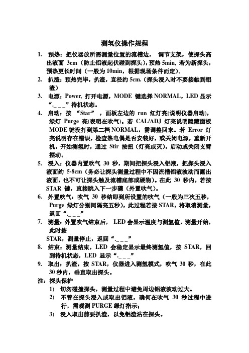
测氢仪操作规程1. 预热:把仪器放所需测量位置的流槽边,调节支架,使探头高出液面3cm (防止铝液起伏碰到探头),预热5min, 若为新探头,预热更长时间(一般为10min,根据现场条件而定)。
2. 扒渣:预热完毕,扒渣,直径约5cm.(探头浸入时不要接触到铝渣)3. 电源:Power, 打开电源,MODE 键选择NORMAL,LED显示“._ _ _”待机状态。
4. 启动:按“Star”,面板左边的run 红灯亮(说明仪器启动),绿灯Purge亮(表明在吹气)。
若CAL/ADJ 灯亮说明隐藏面板MODE键没打到第二档NORMAL,需调整回来。
若Error 灯亮说明存在错误,检查热电偶是否安装好,或关闭电源,重新开机。
开始测氢时,通过Stir 按扭(灯亮或灭),启动或关闭支臂摆动。
5. 浸入:仪器内置吹气30 秒,期间把探头浸入铝液,把探头浸入液面约5-8cm(务必让探头测量过程中不因流槽铝液波动而露出液面,也不可让探头触及流槽底部或硬物)。
在此30 秒内,若按STAR 键,直接跳入下一步骤(外置吹气)。
6. 外置吹气:吹气30 秒结即到所设置的吹气(一般为三次五秒,Purge 绿灯分别间隔亮五秒),此过程若按STAR,将取消测量,返回“._ _ _”7. 测量:外置吹气结束后,LED会显示温度与测氢值,测量开始,此时按STAR,测量停止,返回“._ _ _”8. 结束:测量结束,LED 会稳定显示最终测氢值,按STAR,回到待机状态,LED 显示“._ _ _”9. 取出:扒渣,按STAR,仪器进入测氢模式,吹气30秒,在此30秒内,垂直取出探头。
注:探头保护1) 切勿碰撞探头,测量过程中避免周边铝液波动过大。
2) 不管在探头浸入或取出铝液,确何在吹气30 秒过程中进行,需观测PURGE绿灯指示;3) 浸入取出前要扒渣,以免铝渣沾在探头。
Unisense氢气传感器用户手册说明书

HYDROGEN SENSOR USER MANUALH ydrogen sensor user manual Copyright © 2021· Unisense A/S Version May 2021HYDROGEN SENSOR USER MANUALUNISENSE A/STABLE OF CONTENTS1: WARRANTY AND LIABILITY . . . . . . . . . . . . . . . . . . . . . . . . . . . . . . . . . . . . . . . . . . . . . . . .52: CONGRATULATIONS WITH YOUR NEW PRODUCT! . . . . . . . . . . . . . . . . . . . . . . . . . .6 2:1 S upport, ordering, and contact information63: OVERVIEW . . . . . . . . . . . . . . . . . . . . . . . . . . . . . . . . . . . . . . . . . . . . . . . . . . . . . . . . . . . . . . . . .84: GETTING STARTED . . . . . . . . . . . . . . . . . . . . . . . . . . . . . . . . . . . . . . . . . . . . . . . . . . . . . . . .9 4:1 u npacking a new SenSor9 4:2 p olarization9 4:3 c onnecting the microSenSor9 4:4 p re-polarization10 4:5 c alibration10 Zero hydrogen reading 10 Hydrogen reading 105: MEASUREMENTS . . . . . . . . . . . . . . . . . . . . . . . . . . . . . . . . . . . . . . . . . . . . . . . . . . . . . . . . .13 5:1 m ounting of the SenSorS13 5:2 e lectrical noiSe13 5:3 i nterference14 6: ADVANCED USE . . . . . . . . . . . . . . . . . . . . . . . . . . . . . . . . . . . . . . . . . . . . . . . . . . . . . . . . . .15 7: STORAGE AND MAINTENANCE . . . . . . . . . . . . . . . . . . . . . . . . . . . . . . . . . . . . . . . . . . . .16 7:1 c leaning the SenSor168: REFERENCES . . . . . . . . . . . . . . . . . . . . . . . . . . . . . . . . . . . . . . . . . . . . . . . . . . . . . . . . . . . . . .179: TROUBLESHOOTING . . . . . . . . . . . . . . . . . . . . . . . . . . . . . . . . . . . . . . . . . . . . . . . . . . . . . . . . . . . . . . . . . . . . . . . . . . . . . . . . . . . . . . . . . . . . . . . . . . . . . . . . . . . . . .18 41: WARRANTY AND LIABILITY1:1 n otice to p urchaSerThis product is for research use only . Not for use in human diagnostic ortherapeutic procedures .1:2 w arningMicrosensors have very pointed tips and must be handled with care toavoid personal injury and only by trained personnel .Unisense A/S recommends users to attend instruction courses to ensureproper use of the products .1:3 w arranty and l iabilityThe Hydrogen sensor is covered by a 90 days limited warranty .Microsensors are a consumables . Unisense will only replacedysfunctional sensors if they have been tested according with theinstructions in the manual within 14 days of receipt of the sensor(s) .The warranty does not include repair or replacement necessitated byaccident, neglect, misuse, unauthorized repair, or modification of theproduct . In no event will Unisense A/S be liable for any direct, indirect,consequential or incidental damages, including lost profits, or for anyclaim by any third party, arising out of the use, the results of use, or theinability to use this product .Unisense mechanical and electronic laboratory instruments mustonly be used under normal laboratory conditions in a dry and cleanenvironment . Unisense assumes no liability for damages on laboratoryinstruments due to unintended field use or exposure to dust, humidityor corrosive environments .1:4 r epair or a djuStmentSensors and electrodes cannot be repaired . Equipment that is notcovered by the warranty will, if possible, be repaired by Unisense A/Swith appropriate charges paid by the customer . In case of return ofequipment please contact us for return authorization .For further information please see the document General Terms of Saleand Delivery of Unisense A/S as well as the manuals for the respectiveproducts .52: CONGRATULATIONS WITH YOUR NEW PRODUCT!2:1 s upport, ordering, and contact informationThe Hydrogen microsensor is a miniturized sensor for measuringpartial pressure of H2in the micromolar range .If you wish to order additional products or if you encounter anyproblems and need scientific/technical assistance, please do nothesitate to contact our sales and support team . We will respond toyour inquiry within one working day .E-mail:******************Unisense A/STueager 1DK-8200 Aarhus N, DenmarkTel: +45 8944 9500Fax: +45 8944 9549Further documentation and support is available at our websitewww .unisense .com .REPLACEMENT OF SENSORSUnisense will replace sensors that have been damaged during shipment provided that:• The sensors were tested immediately upon receipt in accordance with the delivery note and the manual• The seal is still intact.• The sensors are returned to Unisense for inspection within two weeks.• The sensors are correctly packed for return to Unisense, in accordance with the note included in the sensor box.6673: OVERVIEWThis manual covers all the Unisense H2 and H2-X sensors . For a complete list of sensors sizes and types please go towww .unisense .com .The standard hydrogen sensor type, the H2-type, is for use in environments where H2S is not expected to occur . The H2S insensitive type, the H2-X-type, has an H2S trap in front of the H2 sensing part, allowing the sensor to be used in H2S containing environments (see “5:3 Interference”) .The Unisense hydrogen microsensor is designed for research applications within physiology, biotechnology, environmental sciences, and related areas .With the minute tip size, excellent response time, and good sensitivity the Unisense hydrogen sensor facilitates reliable and fast measurements with a high spatial resolution .The H2-X sensor has a slightly longer response time than the corresponding H2 sensor .The Unisense hydrogen microsensor is a miniaturizedClark-type hydrogen sensor with an internal reference electrode and a sensing anode . The sensor must be connected to a high-sensitivity picoammeter where the anode is polarized against the internal reference . Driven by the external partial pressure, hydrogen from the environment will pass through the sensor tip membrane and will be oxidized at the platinum anode surface . The picoammeter converts the resulting oxidation current to a signal .Schematic view of a hydrogen sensorwith a LEMO plug.IMPORTANT Unisense sensorsare neitherintended nor approved for use inhumans84: GETTING STARTEDThe H2-type and H2-X-type sensors are used in the same way . Only the sensitivity to H2S and the response time differ between the two types of hydrogen sensors .4:1 u npacking a new sensorWhen receiving a new microsensor remove the shock-absorbing grey plastic net .4:2 p olarizationThe signal from the hydrogen sensor is generated in picoampere . Therefore the hydrogen sensor must be connected to a polarizing picoammeter (e .g . a UniAmp series amplifier) .The anode of the hydrogen sensors should be polarized at +100 mV relative to the cathode . This happens automatically on the Unisense UniAmp series instruments . On the Unisense Multimeter, Monometer and PA-2000 instruments this must be set manually . Please consult the relevant the instrument manual for how to adjust polarization . If you are using a PA2000, please check the polarization voltage before connecting the sensor, since incorrect polarization may destroy the sensor .4:3 c onnecting tHe microsensorInsert the connector into a pA input terminal on the amplifier . The connector contains connections for both internal reference electrode and sensing anode .WARNING Do not remove the seal and protectiveplastic tube before these stepsand calibrationare succesfullycompleted.WARNINGIncorrect polarization may destroy the sensorNOTE The conversionof sensor signal in pA to amplifiersignal in mV is controlled by thePre-Amp Range (mV/pA) setting on the amplifer (notPA-2000)94:4 p re-polarizationJust after connecting the sensor, the signal will be very high and unstable then drop rapidly over the first few minutes . After that the signal will drop slowly for up to 1 hour . Therefore, a periodof polarization is necessary before you can use the sensor . This is called the pre-polarization period .The signal should stabilize at 0-10 picoampere (on the PA2000, the sign will be negative since sensor is positively polarized) forzero hydrogen concentration, depending on the specific sensor .If the sensor is new or has not been operated for several days, it must be polarized for at least 1 hour before it can be calibrated and used . After shorter periods without polarization, the sensor should be polarized until it has exhibited a stable signal for 10 minutes .The signal depends on the specific sensor type (see the value in the specifications that came with the sensor) .If the signal does not stabilize or is too high or too low, refer to the ‘Trouble-shooting’ section of this manual .4:5 c alibrationThe calibration procedure is the same for the H2 and H2-X sensors . Calibration must be performed after the sensor signal has stabilized during pre-polarization .z ero hydrogen readingPlace/keep the sensor tip in water and read the signal . This signal is your calibration value for zero hydrogen conditions .h ydrogen readingThe hydrogen sensor responds linearly and consequently atwo-point calibration is sufficient . Prepare water with a defined hydrogen concentration, which is slightly above the maximum expected concentration to be measured . A defined hydrogen concentration can be obtained by 2 different procedures:IMPORTANT Hydrogen sensorsare sensitive to temperature andsalinity,IMPORTANT Calibration must be performed after pre-polarization when the sensorsignal hasstabilized.Always usea calibration solution with the same temperature and salinity as the sample solution.101 . Use a gas mixture controller to obtain a defined mixture ofhydrogen and hydrogen free inert gas from a gas tank (e .g .N2) as bulk carrier gas . For instance, to obtain a hydrogenconcentration of 40,25 µM in the calibration chamber at 20°C, bubble the water in the calibration chamber vigorously witha gas mixture containing a 95 % N2 and 5 % H2 . The hydrogenpartial pressure is in this case 0 .05 atm, and the Solubility is 805 μmol/L/atm . Multiplying the solubility with the partialpressure results in the concentration: 805 µmol/L/atm * 0,05 atm = 40,25 µM .See Table 1 for more values of the solubility, or use the H2calculator in the Unisense SensorTrace Suite software .Start the software, click “Tools” and select “H2 calculator” . .For a Unisense CAL300 calibration chamber,5 minutes of bubbling at a rate of 5 l perminute is sufficient time to achieve 99 % of theconcentration . If the equipment (gas mixturecontroller) is available, this method can beconvenient, as you can switch between differentconstant hydrogen conditions without changingthe water . Use the solubility table (Table 1),or the H2calculator in the SensorTrace software to find the correct mixture at temperatures other than 20°C .To obtain correct concentrations, the headspace above thewater in the calibration chamber must be closed except fora hole only slightly larger than the microsensor shaft . Thiseffectively prevents ambient air from entering the vessel . We recommend the CAL300 Calibration Chamber for calibrations .2 . Add a defined volume of hydrogen-saturated water to adefined volume of water in a calibration chamber . For instance,1 ml of H2saturated water contains 0,805 µmol at 20°C (see Table 1), or the H2 calculator in the SensorTrace software,and to obtain water with a hydrogen concentration of 10 µM,3 .08 ml hydrogen-saturated water should be added to a totalvolume of 246,9 ml hydrogen free water in the calibrationWARNING Vigorous bubbling water with anygas may cause the water to coolconsiderably.Monitor the temperature tofind a suitablebubbling rate,which does notcool the watersignificantly.Calibration chamber CAL300chamber . After the addition of hydrogen-saturated water tothe calibration chamber mix it thoroughly by moving thesensor in its protection tube up and down for a few seconds and read the signal when it is stable . Do not stir bubbles into the water or mix by bubbling, as this will remove hydrogenfrom the water . A magnetic stirrer is not recommended asa mixing tool as a magnetic stirring can introduce electricalnoise to the signal . The hydrogen in the water will slowlyescape to the atmosphere and the concentration can only be considered constant for a few minutes .Hydrogen sensors respond linearly in the range of 0 to 100 %) and signals can be hydrogen (Low Range sensor from 0 - 10% H2linearly converted to partial pressure .Check and repeat calibration at appropriate intervals to ensure that all measurements can be converted to correct concentrations . When the sensor is new, the appropriate interval may be every2 hours; later it may be 24 hours . To minimize the need for calibrations, keep the sensor polarized between measurements, unless the time between measurements exceeds several days or unless the picoammeter batteries are running out . The membrane permeability of hydrogen microsensors changes with time, so a change in signal of up to 50 % may occur over months .If the sensor functions according to the criteria given in the delivery note, the seal and protective plastic tube can be carefully removed before making measurements.5: MEASUREMENTSThe H2-type sensor should be used in H2S free environments . If H2Sis expected to be present, the H2-X-type sensor should be used .Hydrogen sensors can be used for a wide variety of measurements(see our website for further information www .unisense .com) . Themost common use of hydrogen sensors is for making profiles ine .g . sediment or animal tissue where a high spatial resolution iswanted, or for hydrogen measurements in water samples .5:1 m ounting of tHe sensorsAlthough the Unisense microsensors are made of glass, the tipis flexible and can bend slightly around physical obstacles . Thesensor is thus rather sturdy in the longitudinal direction . However,large obstacles like stones or lateral movements of the sensorwhen the tip is in contact with a solid substrate may cause the tip Array to break .Furthermore, due to the small size of the microsensor tip andto the steepness of gradients in many environments, even adisplacement of the sensor tip of few microns may change itsenvironment .Therefore, we recommend that measurements should beperformed only in a stabilized set-up free of moving or vibratingdevices . We recommend the Unisense lab stand LS and theUnisense micromanipulator MM33 (MM33-2 or MMS) forMicromanipulator laboratory use . For in-situ use, we recommend our in situ stand(IS19) and a micromanipulator .5:2 e lectrical noiseThe signal of the microsensor is very small (10-13 to 10-10 ampere) .Although both the Unisense amplifiers and the UnisenseHydrogen microsensors are very resistant to electrical noise fromthe environment, electrical fields may interfere with the sensorsignal . Therefore, we recommend that unnecessary electrical/mechanical equipment is switched off and the sensor or wires arenot touched during measurements and signal recording .5:3 i nterferenceSulphide in the H2S form may interfere with the H2 measurements . The standard hydrogen sensor, the H2-type, is very sensitive to H2S and other reduced sulphur gases . It should, therefore, not be used in environments where H2S and other reduced sulphur gases are present . The H2-X sensor type is not sensitive to H2S up to 100 µM in solution or 1000 ppm H2S in gas . The H2S trap on the H2-X sensor works by removing protons from the H2S and the ionized formsof sulfide cannot pass through the silicone membrane into the H2 sensing part . Other sulphur gases where protons are less easily removed may still penetrate the silicone membrane . The H2-X sensor may, therefore, still be sensitive to other reduced sulphur gases than H2S . It is recommended to only expose the H2S-X sensor to H2S when needed, to maximize the lifetime of the H2S trap . The H2-X sensor may be made even more resistant to H2S . If you needacustombuiltsensor,*************************6: ADVANCED USEUnisense can construct hydrogen sensors for customer requested applications at additional costs . The most frequently requested construction options are described on our website www .unisense . com .The options include for instance customer specified dimensions, response time, stirring sensitivity, pressure tolerance, range and detection limit . If your specifications for a special hydrogen sensor is not described at our web page please contact sales@unisense . com for further options and prices .6:1 Examples of advanced applications• Consumption/production rates of hydrogen . E .g . during enzyme assays in small samples in Unisense microrespiration chambers MRCh• Measurements of hydrogen under high external pressuree .g . in closed pressurized systems, underwater and deep sea applications• Long-term hydrogen monitoringIfyouhavequestions,*******************************7: STORAGE AND MAINTENANCEStore the sensor in the protective plastic tube used for shipping . The hydrogen microsensor can be stored with the tip exposed to water or air . The room in which the hydrogen microsensor is stored should be dry and not too hot (10-30°C) . If the sensor is used regularly it can be stored polarized .7:1 c leaning tHe sensorDepending on which substance is present on the sensor tip or membrane, the sensor can be cleaned with different solutes .The standard method is to rinse with 96 % ethanol (NOT in the protection tube), then rinse with 0 .01 M HCl and rinse with water . This will remove most substances .Alternatively it is possible to rinse with 0 .1M NaOH, isopropanol or different detergents8: REFERENCES• Revsbech, N . P ., and B . B . Jørgensen . 1986 . Microelectrodes: Their Use in Microbial Ecology, p . 293-352 . In K . C . Marshall (ed .), Advances in Microbial Ecology, vol . 9 . Plenum, New York .• Itoh, T ., et al . 2009 . Molecular Hydrogen Suppresses FcepsilonRI-Mediated Signal Transduction and Prevents Degranulation of Mast Cells . Biochem . Biophys . Res . Commun . 389:651-656 .• Kajiya, M . et al . 2009 . Hydrogen From Intestinal Bacteria Is Protective for Concanavalin A-Induced Hepatitis . Biochemical and Biophysical Research Communications 386:316-321 .• Kajiya, M . et al . 2009 . Hydrogen Mediates Suppression of Colon Inflammation Induced by Dextran Sodium Sulfate . Biochemical and Biophysical Research Communications 386:11-15 .• Vopel, K ., et al . 2008 . Modification of Sediment-Water Solute Exchange by Sediment-Capping Materials: Effects on O2 and PH . Marine and Freshwater Research 59, 1101-1110 .Problem High and drifting signal .Possible cause The sensor tip is broken .Solution Replace the hydrogen microsensor .Problem The signal is very low .Possible cause Damage to internal working electrode .Solution Replace the hydrogen microsensor .Problem Very low sensitivity to H2 and low signal Possible cause 1Bubble in the narrow parts of the sensor,often not visible to naked eyeSolution 1Shake the sensor gently like shaking an oldmercury fever thermometerPossible cause 2Bubble in the sensor tip, not visible to thenaked eyeSolution2Soak the sensor in degassed water for atleast 2 hours . Degas water by boiling it andsubsequently cool it to room temperaturewithout getting air into it .Problem Slow response .Possible cause Insoluble compounds deposited at thesensor tip .Solution Rinse with 96 % ethanol, rinse with 0 .01 MHCl and rinse with water .Problem Unstable signal or the signal fluctuatesif the set-up is touched or equipment isbeing introduced in the medium you aremeasuring in .Possible cause Electrical disturbance of the sensorthrough the tip membrane .Solution Ground the set-up using the bluegrounding cable supplied with theamplifier . Connect the reference plug onthe amplifier (blue plug) with the mediumyou are measuring in .If you encounter other problems and need scientific/technical assistance, please contact **********************************(wewillansweryouwithinoneworkday)Table 1: Equilibrium hydrogen concentrations (µmol/litre) at ambient hydrogen partial pressure of 1 atm. in water as a function of temperature.Ref. Wiesenburg and Guinasso 1979. J.Chem Eng. Data 24(4):356-36021·*****************。
炜盛科技 ME2-H2 氢气传感器 使用说明书
氢气气体传感器(型号:ME2-H2)使用说明书版本号:1.0实施日期:2016-04-10郑州炜盛电子科技有限公司Zhengzhou Winsen Electronic Technology Co., Ltd声明本说明书版权属郑州炜盛电子科技有限公司(以下称本公司)所有,未经书面许可,本说明书任何部分不得复制、翻译、存储于数据库或检索系统内,也不可以电子、翻拍、录音等任何手段进行传播。
感谢您使用炜盛科技的系列产品。
为使您更好地使用本公司产品,减少因使用不当造成的产品故障,使用前请务必仔细阅读本说明书并按照所建议的使用方法进行使用。
如果用户不依照本说明书使用或擅自去除、拆解、更换传感器内部组件,本公司不承担由此造成的任何损失。
您所购买产品的颜色、款式及尺寸以实物为准。
本公司秉承科技进步的理念,不断致力于产品改进和技术创新。
因此,本公司保留任何产品改进而不预先通知的权力。
使用本说明书时,请确认其属于有效版本。
同时,本公司鼓励使用者根据其使用情况,探讨本产品更优化的使用方法。
请妥善保管本说明书,以便在您日后需要时能及时查阅并获得帮助。
郑州炜盛电子科技有限公司ME2-H2 氢气传感器产品描述ME2-H2氢气传感器是燃料电池型传感器,氢气和氧气在工作电极和对电极上发生相应的氧化还原反应并释放电荷形成电流,产生的电流大小与氢气浓度成正比并遵循法拉第定律,通过测定电流的大小即可判定氢气浓度的高低。
传感器特点低功耗、高精度、高灵敏度、线性范围宽、抗干扰能力强、优异的重复性和稳定性。
主要应用广泛适合商业特别是民用领域的氢气浓度检测。
技术指标表1项目参数检测气体氢气(H2)量程0~30000ppm最大测量限40000ppm灵敏度(2±1)nA/ppm分辨率50ppm响应时间(T90)<30S负载电阻(推荐)200Ω重复性<3﹪输出值稳定性(/年)<10﹪输出线性度线性零点漂移(-40℃~90℃)≤100ppm温度范围-20℃~50℃湿度范围15﹪~90﹪RH压力范围标准大气压±10﹪使用寿命3年图1:传感器结构图基本电路图2: ME2-H2测试电路(R4根据需要可更换)传感器特性描述图3:传感器的灵敏度、响应恢复情况图4:传感器线性曲线交叉干扰特性ME2-H2传感器能对除目标气体外的其它气体产生响应。
测氢仪的用法与正常范围

测氢仪的用法与正常范围1. 嘿,你知道测氢仪咋用不?其实很简单啦!就像你用温度计测量体温一样,把测氢仪的探头放到要检测的地方就行啦。
比如说检测一个储存氢气的罐子,看看里面氢气含量正不正常。
正常范围呢,一般是根据具体情况而定的哟!2. 哇塞,测氢仪的用法可别小瞧呀!它就像是你的好帮手。
比如你在一个工厂里,用它来检测设备有没有氢气泄漏,多重要呀!正常范围就像一个安全线,不能超过也不能太少呢,你说是不是呀!3. 哎呀呀,测氢仪用法超容易上手呢!好比你打开手机那么自然。
比如你在研究一个新的能源项目,用测氢仪来确定氢气的精准含量。
它的正常范围就好像比赛的规则,可不能违反呀!4. 嘿哟,测氢仪怎么用你还不知道呀?很简单哒,就如同你使用筷子夹菜一样。
比如要检查一个氢气管道是否安全,就得靠它啦!正常范围那可是很关键的,就像游戏里的得分范围一样,不能乱来呀!5. 哇哦,测氢仪使用方法来啦!想象一下,就跟你拿钥匙开门一样轻松。
比如在实验室里,要用它来检测化学反应产生的氢气对不对。
那正常范围呢,可不就是一个标准,得好好遵守呀!6. 哈哈,测氢仪的使用还不简单嘛!就好像你系鞋带那么容易操作。
比如在一个氢气加气站,用它检测充气是否达标。
正常范围就像是给你画好的路线,得照着走呀!7. 嘿嘿,测氢仪的用法不难哦!就如同你听音乐选歌那么自然。
比如在检查一个氢气燃料电池,靠它来确定性能。
正常范围就像是给汽车规定的速度限制,不能乱开呀!8. 哟哟哟,测氢仪咋用知道不?其实不难的啦!好比你拿笔写字一样顺手。
比如要检测一间氢气存储室,全靠它啦!那正常范围呢,绝对是很重要的呀,可别不当回事儿!我的观点结论:测氢仪的用法不难掌握,只要清楚操作步骤,找到合适的检测场景,就能很好地发挥它的作用,而正常范围是判断检测结果是否可靠的重要标准,一定要重视呀!。
氢传感器电压传感器安全操作及保养规程
氢传感器电压传感器安全操作及保养规程引言氢传感器电压传感器是一种重要的仪器设备,广泛应用于各种工业领域。
为了确保其正常运行和使用安全,本文将介绍氢传感器电压传感器的安全操作注意事项和保养规程。
1. 安全操作注意事项在操作氢传感器电压传感器时,需要遵循以下安全操作注意事项:1.1. 仅限专业人士操作氢传感器电压传感器是一种高科技仪器,只有专业人士才能进行操作。
非专业人士请勿擅自操作,以免造成人身伤害或设备损坏。
1.2. 佩戴个人防护装备在操作氢传感器电压传感器时,操作人员应佩戴适当的个人防护装备,包括防护眼镜、防护手套和防护服等,以确保个人安全。
1.3. 保持操作环境清洁操作氢传感器电压传感器时,操作环境应保持干净整洁,避免杂物和液体进入仪器内部,防止因此造成设备损坏或故障。
1.4. 避免过度使用在使用氢传感器电压传感器时,避免过度使用,以免超过其额定工作时间,导致设备过热或短路等安全隐患。
1.5. 注意电源连接在连接电源时,务必检查电压和电流是否与仪器要求相符,避免过高或过低的电源电压导致设备损坏或发生火灾。
2. 保养规程为了保障氢传感器电压传感器的正常运行和延长其使用寿命,以下是保养规程的具体步骤:2.1. 定期清洁外壳定期清洁仪器的外壳,使用干净的软布擦拭,并避免使用化学溶剂或腐蚀性液体,以防损坏外壳。
2.2. 检查连接线路定期检查仪器的连接线路,确保线路的连接牢固并无松动现象。
如发现松动,应及时处理以避免影响仪器的正常工作。
2.3. 定期校准和维修定期进行校准和维修工作,确保仪器的准确度和稳定性。
校准和维修应由专业人员进行,遵循相关的操作规程和要求。
2.4. 避免湿气和腐蚀物质氢传感器电压传感器应存放在干燥通风的环境中,避免接触湿气和腐蚀物质,以延长仪器的使用寿命。
2.5. 定期更换配件按照使用说明书上的要求,在规定的时间内更换仪器中的耗材和易损件,以确保仪器的正常工作和准确度。
结论以上是氢传感器电压传感器的安全操作注意事项和保养规程。
在线氢气检测仪安全操作及保养规程
在线氢气检测仪安全操作及保养规程一、前言氢气是一种具有高度危险性的气体,对人体有可能造成严重伤害或致命危险,因此,安全操作和保养是使用氢气检测仪时必须注意的事项。
本文档为使用在线氢气检测仪时的安全操作及保养规程,从以下几个方面阐述。
二、使用前准备为了确保在线氢气检测仪使用的安全和有效,使用前需要落实以下几个方面的工作:1.培训使用氢气检测仪的工作人员必须接受企业的相关培训,并且具备相关认证。
在使用在线氢气检测仪之前,需要进行相关安全操作培训,并要求有经验的监护人员的陪同下进行操作。
2.环境评估在使用在线氢气检测仪之前,需要评估使用环境的安全性。
评估应包括氢气泄漏的潜在危害、环境条件和设备维护情况等。
对于没有得到充分评估的环境,需要停止使用在线氢气检测仪。
3.操作手册在使用在线氢气检测仪之前,需要认真阅读相关的操作手册。
对于第一次使用氢气检测仪的人员,操作手册提供详细和清晰的说明,这个过程非常重要。
4.维护检查氢气检测仪的状态和性能,确保它在最好状态下运行。
确保传感器是干净和完好的。
检查检测仪是否有氧气、氮气等有害气体的存在,并清除它们。
三、安全操作使用氢气检测仪应注意以下几个方面的安全操作:1.使用期限在线氢气检测仪具有一定的使用期限,在其到期前应立即报废。
否则可能导致安全问题,甚至出现错误数据读取。
2.使用环境氢气检测仪应使用在干燥、温度适宜、通风良好和保护光线的环境中。
在可能存在氧气、氮气等有害气体的环境中,应特别注意安全操作。
3.安装将在线氢气检测仪和其传感器正确安装在有可能泄漏氢气的设备位,它需要时刻监测氢气的泄漏情况。
4.使用过程在使用氢气检测仪时,工作人员应把注意力集中在仪器的读数上,并做好必要的记录和分析。
当出现有害气体泄漏风险时,应及时停止检测并开启适当的设备进行应急处理。
5.移动使用在氢气检测仪的移动过程中,需要特别注意传感器的碰撞防护和仪器的稳固固定。
四、保养规程保养在线氢气检测仪可以确保其性能和寿命,以提高其可靠性和使用有效性。
系列氢气分析仪安全操作及保养规程
系列氢气分析仪安全操作及保养规程一、前言氢气分析仪是实验室中常用的分析仪器,它能够准确测量氢气的浓度。
然而,如果不注意使用和保养规程,就会导致设备故障或者对人员造成安全威胁。
因此,本文将介绍氢气分析仪的安全操作和保养规程,以便使用人员遵循。
二、安全操作1. 环境安全在使用氢气分析仪前,需要保证仪器周围的环境安全。
避免使用在过于潮湿、尘土飞扬、高温或低温的环境下,以免引起设备不稳定、故障或者危险的情况出现。
2. 操作前准备在使用氢气分析仪前,需要进行必要的操作前准备。
首先,接到电表上的电压需正常,检查氢气源是否正确接入仪器管路,接地电源符合安装要求。
其次,先观察氢气分析仪的仪器显示屏是否正常,根据需要进行必要的校准。
3. 使用设备在使用氢气分析仪时,需要注意以下几点:•避免水分进入系统,对仪器产生负面影响。
•不要对仪器进行自行拆卸、更换或维修。
•确保好仪器的电源开关,避免误触。
•不要超过氢气分析仪的测量范围和限制,不要给仪器带来额外的压力和侵害。
•操作过程中,随时关注氢气分析仪的显示屏,以便实时观察数据变化,发现问题及时处理。
4. 停用设备使用完氢气分析仪后,应当妥善停用设备,做好后续保养。
首先,关闭氢气分析仪的电源开关,并将电线从插座中拔出。
然后,将仪器放置于干燥、通风良好、避免热、光、潮湿的地方存放。
同时,将各部件清理干净,预防灰尘、污垢的堆积。
三、保养规程1. 定期检查仪器氢气分析仪的各个部位要定期检查,先解开运行中的氢气分析仪管路,使用吸球将正在测量的氢气吸出来,防止管路堵塞。
然后将仪器的表面用清水和温和的肥皂水擦拭干净,吸去余留的水份和氢气,并确保仪器的清洁干净。
此外,管理员每半年必须进行一次氢气分析仪的检查,或者在氢气分析仪信号不稳定时随时进行检查。
2. 更换管路在使用过程中,氢气分析仪的管路容易受到涂有化学药品、酶、创口贴、粉末、水汽等影响,并导致污染,因此,在管路检查之后,管理员需要更换氢气分析仪的管路,以便保证仪器的准确性和测量效果,同时避免不必要的故障和危险事故产生。
氢气分析系统安全操作及保养规程

氢气分析系统安全操作及保养规程氢气分析系统是一种常见的分析仪器,在工业、环保、食品等领域广泛应用。
为了确保仪器的正常运行和人员的安全,有必要制定相关的操作和保养规程。
一、仪器安全操作规程1.1 前置操作要求在操作氢气分析系统前,请确保安装工作已经完成,氢气分析系统与氢气供应负责单位联系,掌握氢气使用情况。
1.2 启动仪器步骤1.打开系统电源,仪器开机自检。
2.检查仪器连通性,确保氢气分析系统与其他仪器正常连接。
3.打开氢气阀门,向氢气分析瓶中通氢气。
4.扫描气体色谱仪二维码,开启气体色谱软件,按照软件操作流程进行氢气分析。
1.3 操作注意事项1.操作前请穿戴电阻稳定、不产生静电的服装,操作人员应当戴上防静电手套。
2.操作期间严禁吸烟、喝饮料或食物。
3.操作人员不得离开现场,确保仪器运行过程中安全。
4.发现仪器运行异常或气体泄漏等情况,应立即停机并报告相关责任人。
1.4 关机及清洁操作1.关闭氢气供应阀门,等待仪器排气完毕。
2.关闭仪器电源。
3.清洁仪器外壳及仪器头部,保持仪器干净整洁。
二、仪器保养规程2.1 定期维护氢气分析系统需定期进行维护,如校准、更换气源、清洁仪器等工作。
2.2 气源更换使用氢气分析系统期间,需根据仪器使用情况及压力情况定期更换气源。
2.3 冷却液更换仪器冷却液每使用半年或根据使用情况适当延长更换周期,需要定期更换冷却液。
更换冷却液时,请按照以下步骤进行:1.关闭氢气供应阀门,待仪器排气完成后,将仪器头部锁住,取下仪器。
2.将冷却液放入冷却液桶中,将冷却液加入仪器头部。
3.注意正常连接仪器管路、液位情况,确保液位及流量均匀。
4.打开氢气供应阀门,进行氢气分析。
2.4 保养注意事项1.对仪器进行保养时,确保仪器处于关闭状态,并断开电源。
2.仪器使用过程中出现任何异常情况,应立即停止使用,并通知相关责任人进行维护。
3.定期检查气源情况、气源压力,确保供气连续稳定。
三、总结氢气分析系统是一种普遍应用的分析仪器,在日常操作中需要对仪器进行安全操作和保养。
氢气H2浓度检测探头

氢气H2浓度检测探头氢气H2浓度检测探头氢气H2浓度检测探头产品描述:氢气H2浓度检测探头适用于各种环境和特殊环境中的氢气H2氢气H2气体浓度和泄露,在线检测及现场声光报警,对危险现场的作业安全起到了预警作用,此仪器采用进口的电化学传感器和微控制器技术,具有信号稳定,精度高,重复性好等优点,防爆接线方式适用于各种危险场所,并兼容各种控制器,PLC,DCS等控制系统,可以同时实现现场报警和远程监控,报警功能,4-20mA标准信号输出,继电器开关量输出。
氢气H2浓度检测探头产品特性:进口电化学传感器具有良好的抗干扰性能,适用寿命8年。
采用先进微处理技术,响应速度快,测量精度高,稳定性和重复性好。
检测现场具有具有现场声光报警功能,气体浓度超标即时报警,是危险场所作业的安全保障。
4现场带背光大屏幕LCD显示,直观显示气体浓度,类型,单位,工作状态等。
5独立气室,更换传感器无须现场标定,传感器关键参数自动识别。
6全量程范围温度数字自动跟踪补偿,保证测量准确性。
检测气体:空气中的氢气H2气体检测范围:0~100ppm,0~200ppm,0~1000ppm,0~1000ppm,0~5000ppm,10 0%LEL可选。
分别率:0.01ppm(0~100ppm);0.1ppm(0~1000ppm);1ppm(0~10000ppm 以上);0.1LEL.工作方式:固定式连续工作,扩散式,管道式,流通时,泵吸式可选。
检测误差:≦1%(F.S)响应时间:≦10S输出信号:电流信号输出4-20MA报警方式:2路无源节点信号输出,报警点可设置。
工作环境:-20℃~50℃(特殊要求:(-40℃~+70℃)相对湿度:≦90%RH工作电压:DC12~30V传感器寿命:3年防爆形式:探头变送器及传感器均为隔爆型。
防爆等级:Exd II CT6连接电缆:三芯电缆(单根线径≧1.5mm);建议选用屏蔽电缆。
连接距离:≦1000m.防护等级:IP65.外形尺寸:183X143X107mm.重量:1.5Kg.氢气H2浓度检测探头简单介绍:氢气H2浓度检测探头●自动温度补偿,零点,满量程漂移补偿●防高浓度气体冲击的自动保护功能●全软件校准功能,用户也可自行校准,用3个按键实现,操作简单●二线制4-20mA输出氢气H2浓度检测探头应用场所医药科研、制药生产车间、烟草公司、环境监测、学校科研、楼宇建设、消防报警、污水处理、工业气体过程控制石油石化、化工厂、冶炼厂、钢铁厂、煤炭厂、热电厂、、锅炉房、垃圾处理厂、隧道施工、输油管道、加气站、地下燃气管道检修、室内空气质量检测、危险场所安全防护、航空航天、军用设备监测等。
H2PEM用户使用手册
按回车键,显示显示流量 112 表示当前流量 ml/MIN 4292 表示已产生了 4292 L H2.
3.3.1 Standby Mode 按 键并保持,进入待机状态,可暂停氢气供应。再按 键返回常规状态。
3.3.2 Reset Mode 当出现错误,要求复位时,按 键
3.4 关机 1. 气体发生器的设计是 24 小时连续运行的. 2. 当不需要氢气时,气体发生器停止工作,保持压力不变。当压力下降时,气体发生器开始 工作. 3. 确认不再需要使用 H2. 4. 关闭电源开关,从主电源上拔下插头. 5. 慢慢卸下发生器的供气管道,系统卸压. 6. 供气口用盲螺母拧紧(随机). 7. 长时间不用时,关闭电源,请每周开机一次,建议每次 30 分钟.
电导率高
是
排水并加去离子水 >1Mohm-cm
电导率过高
否
压力出错
错误信息/原因 压力系统H2漏
压力剧降
H2漏
氢气产生 否
否
对策 检查干燥柱是否安装到位 检查内部压力电路 咨询 Parker 检查出口管路和连接 如不能解决,联系 Parker 维修
否
检查干燥柱是否安装到位
检查内部压力电路
咨询 Parker
7
4.8 维修周期
行动 检查电源指示灯
每天
每周
检查STATUS / FAULT指示灯
检查水位
检查水质
每6个月
每2年
8
检查泄漏
检查干燥剂柱,指示剂材料变成 不透明时更换 6个月维修包
24个月维修包
观察,
基本步骤
5 故障排除
万一设备出现问题,此故障排除指南可以用来识别可能的原因和采取补救措施。
当发生错误时,液晶屏将轮流显示常规菜单和错误信息。另外,机身上的系统检查指示灯、
- 1、下载文档前请自行甄别文档内容的完整性,平台不提供额外的编辑、内容补充、找答案等附加服务。
- 2、"仅部分预览"的文档,不可在线预览部分如存在完整性等问题,可反馈申请退款(可完整预览的文档不适用该条件!)。
- 3、如文档侵犯您的权益,请联系客服反馈,我们会尽快为您处理(人工客服工作时间:9:00-18:30)。
H2SMARTUSER MANUALLEGAL NOTICEMay 2008 – Revision 1THIS MANUAL IS SUPPLIED IN ONE (1) COPY.No part of this publication may be duplicated, copied, and/or transmitted without the prior written permission of United Process Controls.The information contained in this document is STRICTLY CONFIDENTIAL and PROPRIETARY to United Process Controls, and shall not be: i) reproduced or disclosed in part or in whole, ii) used for any design or manufacturing of heat treating and/or control equipment, or any other purpose except for that which it is supplied under the terms of the Contract, unless the express written authorization is obtained from United Process Controls.Drawings and photographs included in the documentation are the property of United Process Controls, and it is strictly forbidden to reproduce them, transmit them to a third party, or use them for manufacturing and/or design of equipment. Sub-licensing of any technical information contained in this Documentation is strictly forbidden under the terms of the Contract.United Process Controls reserves the right to modify this document without prior notice. WARRANTYUnited Process Controls (UPC) warrants its goods as being free of defective materials and faulty workmanship. Contact your local sales office for warranty information. If warranted goods are returned to UPC during the period of coverage, UPC will repair or replace without charge those items it finds defective. The foregoing is Buyer's sole remedy and is in lieu of all other warranties, expressed or implied, including those of merchantability and fitness for a particular purpose. Specifications may change without notice. The information we supply is believed to be accurate and reliable as of this printing. However, we assume no responsibility for its use.CE Conformity (Europe)This product conforms to 73/23/EEC, the Low Voltage Directive, and 89/336/EEC, the EMC Directive.AMS Conformity (North America)This product conforms to SAE Aerospace Material Specifications AMS 2759/10 for nitriding and 2759/12 for nitrocarburizingTABLE OF CONTENTS1. INTRODUCTION (5)1.1. Overview (5)2. SPECIFICATIONS (6)2.1. Physical (6)2.2. Performance (6)2.3. Operating (6)2.4. Calibration (recommendation) (6)3. INSTALLATION (7)3.1. Overview (7)3.2. Panel Mount Model (7)3.3. Port Mount Model (10)3.4. Installation Steps – Panel Mount (14)3.4.1.Step 1 (14)3.4.2.Step 2 (14)3.4.3.Step 3 (15)3.4.4.Step 4 (16)3.5. Installation Steps – Port Mount (16)3.5.1.Step 1 (16)3.5.2.Step 2 (17)3.5.3.Step 3 (18)4. ELECTRICAL INSTALLATION (19)5. OPERATING INSTRUCTIONS (26)6. MAINTENANCE (27)6.1. Sample Gas Filter (27)6.2. Sample Gas Pump (29)7. CONFIGURATION (29)8. CUSTOMER SUPPORT (29)8.1. Contacts (29)TABLE OF FIGURESFigure 1 Panel Mount Model (7)Figure 2 Panel Mount Front View (8)Figure 3 Panel Mount Side View (9)Figure 4 Panel Mount Bottom View (10)Figure 5 Port Mount Model (10)Figure 6 Port Mount Front View (11)Figure 7 Port Mount Side View (12)Figure 8 Port Mount Side View (13)Figure 9 Panel Mount Step 1 (14)Figure 10 Panel Mount Step 2 (14)Figure 11 Panel Mount Step 3 (15)Figure 12 Panel Mount Step 3 (15)Figure 13 Panel Mount Step 4 (16)Figure 14 Port Mount Step 1 (16)Figure 15 Port Mount Step 1 (17)Figure 16 Port Mount Step 2 (17)Figure 17 Port Mount Step 3 (18)Figure 18 Electrical Installation (19)Figure 19 Connectors (21)Figure 20 Connectors (22)Figure 21 LAN Connector (23)Figure 22 CAN Connector (23)Figure 23 Filter Cover (27)Figure 24 Filter Holder (28)Figure 25 Filter Cartridge (28)1. INTRODUCTION1.1. OverviewThe H2Smart is an integrated sampling system designed to measure hydrogen content with high accuracy in nitriding and nitrocarburizing atmospheres and to calculate the parameters necessary for process control. A unique measuring cell design and advanced electronics eliminate the need for a reference gas cell, thus simplifying the installation.An integrated sampling pump with variable output and a flow monitoring circuit with alarm and pump saturation warning insure reliable sampling. The pump provides a continuously controlled flow despite most sampling line obstructions or filter contaminations, thus assuring accurate measurements and better process control. In addition, an alarm is triggered notifying that the lines are clogged.The sample gas flow is measured with a thermal mass flow meter with integrated thermal conductivity compensation ensuring accurate flow measurement for all gas compositions of the specified gas system. A sample gas pump with variable output and a digital flow regulator are used to form a closed loop sampling system that ensures constant gas flow through the analyzer.The measuring block is maintained at a set temperature to protect the system from moisture formation and cell contamination during nitrocarburizing and post oxidation processes.The system status and measured results are displayed on a large, easy to read alphanumerical display.2. SPECIFICATIONS2.1. PhysicalPanel mount modelWidth (including mounting bracket): 7.28” (185mm)Height: 8.25” (209.53mm)Depth: 7.6” (193mm)Weight: 8.8 lbs (4 kg)Furnace Port mount modelWidth: 5.91” (150mm)Height: 9.88” (251mm)Depth: 7.13” (181mm)Weight (including flange): 9.9 lbs (4.5 kg)2.2. PerformanceAccuracy: +/- 0.5% of reading+/- 0.2% of full scaleLinearity: < 0.5% of full scaleRepeatability: < 0.5% of full scaleZero drift: < 0.5% of full scale per month Sampling flow: 0.2 - 0.5 lpm / .42 - 1 cfhResponse time: 95% in 30 sec @ 0.5 lpm / 1 cfh2.3. OperatingPower requirements: 24VDC, 2.5 Amps max. Use only well regulated power supplyOutputs: 2 x analog, isolated with common positive rail4 – 20 mA (R<500 Ohm)1 x digital, PWM output 24 VDC2 x digital, 24 VDC, 1.5 A maxInputs: 1 x analog, temperature sensor2 x digital, 24 VDC2.4. Calibration (recommendation)Zero Calibration*every 6 months (or as required) Span Calibration not requiredFactory calibration once every 5 years*Zero calibration kit required3.INSTALLATION3.1. OverviewThe H 2Smart can be mounted in two different ways; panel mounting or port mounting.Panel mounting is typically used when the unit is located away from the furnace and the sample gases are tapped from the exhaust lines. This can be the method of choice when installation on the furnace cover is impractical and furnace body installation is not an option.When the port mounting option is chosen, the unit is installed directly on the furnace lid or body provided that a KF 50 adapter is available. This method may be desired due to its minimal piping requirements and quick response as the unit is directly in the work zone.3.2. Panel Mount ModelThe panel mount model allows for the mounting of the H 2Smart anywhere away from the furnace. Two brackets and four screws are used to attach the sensor.Figure 1 Panel Mount ModelCAUTIONHandle with care, do not drop. The sensor is susceptible to shock, and it is a static sensitive device, use proper handling proceduresPANEL MOUNT FRONT VIEWFigure 2 Panel Mount Front View1 Optional Interface for5 Digital I/OProfibus or Modbus 6 Analog Out2 CAN 7 Taux (temp sensor)3 SVC (service) 8 Gas Filter Cover4 LAN 9Digital DisplayPANEL MOUNT SIDE VIEW “V”Figure 3 Panel Mount Side ViewPANEL MOUNT BOTTOM VIEWFigure 4 Panel Mount Bottom View3.3. Port Mount ModelThe port mount option allows for the mounting of the H2Smart directly on the furnace port of the furnace cover. A KF50 flange is attached to the unit and then fastened to the port using a KF50 connector.Figure 5 Port Mount ModelPORT MOUNT FRONT VIEWFigure 6 Port Mount Front View1 Optional Interface for5 Digital I/OProfibus or Modbus 6 Analog Out2 CAN 7 Taux (temp sensor)3 SVC (service) 8 Gas Filter Cover4 LAN 9Digital DisplayPORT MOUNT SIDE VIEW “V”Figure 7 Port Mount Side ViewPORT MOUNT SIDE VIEWFigure 8 Port Mount Side View3.4.INSTALLATION STEPS – PANEL MOUNT3.4.1.Step 1Attach bracket to panel wall using four #10 (M5) screwsFigure 9 Panel Mount Step 13.4.2. Step 2Attach tubing to ExhaustFigure 10 Panel Mount Step 2Connect 1/4” tubing to Swagelok connector using two wrenches (5/8” and 9/16”) * Follow Swagelok instruction to assemble piping with tube fitting.Figure 11 Panel Mount Step 3Figure 12 Panel Mount Step 3Assembly Instructionsa) Insert tubing into the Swageloktube fitting.b) Make sure that tubing rests firmlyon the shoulder of the tube fitting body and that the nut is finger-tight.c) Scribe the nut at 6 o’clock position d) While holding fitting body steady,tighten the nut 1 1/4 turns to the 9 o’clock position.Reassembly Instructionsa) Insert tubing with pre-swaged ferrules into fitting body until the front ferrule seats. b) Rotate the nut with a wrench to the previously pulled-up position. At this point, asignificant increase in resistance will be encountered.c) Tighten slightly with the wrench. Note: don’t use the gap inspection gauge withreassembled fittings.For Ferritic Nitrocarburizing furnaceFigure 13 Panel Mount Step 4 Use pipe insulation with heat tracing3.5. INSTALLATION STEPS – PORT MOUNT3.5.1. Step 1Connect 1/4” tubing to Swagelok connector using two wrenches (5/8” and 9/16”) * Follow Swagelok instruction to assemble piping with tube fitting.Figure 14 Port Mount Step 1Figure 15 Port Mount Step 1 Assembly Instructionsa) Insert tubing into the Swageloktube fitting.b) Make sure that tubing restsfirmly on the shoulder of thetube fitting body and that thenut is finger-tight.c) Scribe the nut at 6 o’clockpositiond) While holding fitting bodysteady, tighten the nut 1 1/4turns to the 9 o’clock position.Reassembly Instructionsa) Insert tubing with pre-swaged ferrules into fitting body until the front ferrule seats.b) Rotate the nut with a wrench to the previously pulled-up position. At this point, asignificant increase in resistance will be encountered.c) Tighten slightly with the wrench. Note: don’t use the gap inspection gauge withreassembled fittings.3.5.2. Step 2Attach the KF50 flange to the casingFigure 16 Port Mount Step 23.5.3. Step 3Attach the K50 flange to the furnace port with a KF50 connectorFigure 17 Port Mount Step 34. ELECTRICAL INSTALLATIONConnect the system to a well regulated 24VDC power supply capable of supplying 2.5A minimum.Connect power cable to 24 V power supplyFigure 18 Electrical InstallationWithin the specified limits, the value of the supply voltage will not influence the accuracy, but a power supply with bad stability may increase measurement noise of the system. Use a well regulated power supply and do not operate other heavy loads from the same supply.The specified power consumption is only true during start-up, after operatingtemperature is reached, the power consumption will decrease to 20% - 40% of the specified value, depending on ambient temperature.Heat tracing the sample gas tubesIn order to avoid clogging of the sample gas tubes by ammonium carbonate and condensation, the sample tubes should be kept at temperatures above 149°F (65°C) by heat tracing. For this purpose typically, a heat trace cable is run close to the tube bundle, tightly pressed against the tubes by appropriate cable ties. The whole assembly is then wrapped in thermal insulation material, e.g. Armaflex foam tubing.CAUTIONThe H 2Smart will be permanently damaged if connected to 115 or 230VACprovides the necessary temperature regulator to operate the heat cable. To use this feature1. Mount the optional heat tracing temperature sensor to the tube bundleinside the thermal insulation, at a distance of 1 ft (30cm) from the H2Smartconnectors.2. Use an appropriate solid state relay controlled by the heat tracing controloutput to switch power to the heat tracing cable.See the wiring diagram below for more information.The H2Smart will regulate the heat tracing temperature to 149°F (65°C) as long as it is powered up without further user action.Figure 19 ConnectorsFigure 20 ConnectorsFigure 21 LAN Connector LAN 10BaseT Female DB-9 connectorFigure 22 CAN ConnectorCAN Male DB-9 connectorH2Smart digital input and output signalsConnector X1 is a 15pin DSUB male connectorPin Signal name Signal function1 +DigIn12 -DigIn1A 24VDC signal on DigIn1 enables sampling.3 +DigIn24 -DigIn2Reserved5 DigOut4 Open collector output. A low output signal indicates thestatus "Flow rate off limits" (flow alarm).6 DigOut3 Open collector output. A low output signal indicates apump saturation status (pump alarm).7 DigOut2 Open collector output. Outputs a 10Hz pulse widthmodulated signal used to control the power of the heattracing heater via a solid state relay. ***Caution Do notuse an electromechanical relay for this purpose***8 0V external loadsupply Connect to negative terminal of the external load power supply.9 Reserved10 Reserved11 Reserved12 Reserved13 Reserved14 Reserved Pins are reserved for future use, make no connections to them.15 0V external loadsupply Connect to negative terminal of the external load power supply.Digital inputs are electrically isolated from ground and each other.-Max. Input voltage is 28VDC-input Current is 6mA@24VDC.Digital outputs are open collector outputs referred to pins 8 and 15 of connector X1 (0V external load supply). Be aware that pins 8 and 15 of X1 are internally connected to 0V of the system power supply input.H2Smart analog outputsConnector X2 is a 9pin DSUB female connectorPin Signal name Signal function1 +AnaOut12 -AnaOut1Analog output 13 +Anaout24 -AnaOut2Analog output 25 Shield GND Cable shield connection, connected to PE6 Reserved7 Reserved8 Reserved9 Reserved Pins are reserved for future use, make no connections to them.***Caution***+AnaOut1(Pin 1) and +Anaout2(Pin 3) are internally connected.To avoid interference between both outputs, do not connect externallyThe analog outputs of H2Smart are internally powered 4 - 20mA current sources with common isolation, able to drive a maximum loop resistance of 500 ohms. Output assignment, scaling and electrical output range (0 - 20mA or 4 - 20mA) may be configured using the H2Smart service software.Factory default configuration:Output value Measurement result (H2% or dissociation%depending on calibration type)Analog output 1Scaling 0 -100% = 4 - 20mARange 4 - 20mAOutput value Sample gas flow rate [l/min]Analog output 2Scaling 0 – 1 l/min = 4 - 20mARange 4..20mAHeat tracing sensor connectorConnector X3 is a 9pin DSUB male connector. It is exclusively used for the optional heat tracing temperature sensor that enables H2Smart to control the temperature of the sample gas tube heat tracing.Do not connect anything else to this connector.5. OPERATING INSTRUCTIONSAfter power on, the system starts heating up to operational temperature, nominally 65°C. Flow measurement is disabled and the sampling pump is off during heat up to avoid contamination of the system with condensation. Depending on ambient temperature, heat up takes about 30 minutes, full accuracy is reached after 1h. It is recommended to keep the system powered up all times, using the "Sampling enable" digital input to activate or deactivate sampling.When the operating temperature is reached, the "Sampling enable" digital input must be activated to enable flow measurement and the sample gas pump.DisplayThe display shows the following information, depending on the system status:Display shows: StatusFlashes: Temp/Heat up or sampling disabledPump OffSampling enabledProcess Variable i.e. % diss.,K N, etc.Filter Sampling pump nearingsaturation, most probably dueto a clogged gas filterAlarm Sampling enabled, but thesample gas flow is outside theflow tolerance band6. MAINTENANCEAll maintenance must be carried out by trained personal only in compliance with the applicable safety standards.6.1. Sample gas filterMaintenance period Once per year or when H2Smartindicates a "Filter" alarm. Depending on the operating environment a shorterperiod may be required. Action Change the filter elementFilter element type Swagelok SS-4F-K4-7Tools needed A flathead screwdriverA 10mm Allen key1. Purge the furnace or process reactor with an inert gas (e.g. nitrogen) to makesure no burnable or explosive gas is left in the system.2. Disable sampling by deactivating the "Sampling enable" digital input signal.3. Use the screwdriver to remove the black filter cover on the front panel ofH2Smart.Figure 23 Filter CoverRemove filter cover4. Remove the filter holder using the 10mm Allen wrench.Figure 24 Filter Holder5. Remove the old filter cartridge. If necessary, use a pair of pliers for this task.Figure 25 Filter Cartridge6. Insert the new filter cartridge and reinstall the filter holder. Tighten the filter holderuntil it hits the final stop, but there is no need to apply much force to compress the seal.7. Reinstall the filter cover on the front panel.6.2. Sample gas pumpMaintenance period The life time of the sample gas pump is dependent on thecomposition of the gas.Action Replace the sample gas pumpGas pump type H2Smart gas pump assembly,part no. 1888Send the unit in for service in case of a pump failure.7. CONFIGURATIONField configuration of the H2Smart is limited to setting the IP parameters, selecting the temperature display unit (°C or °F) and configuring the analog outputs.All configurations are done using the H2Smart service software installed on a PC running Windows® XP O/S.There are two ways to connect to the H2Smart:•Using a standard UPC service cable to connect a standard Com port on your computer to the service port on H2Smart. This includes setting up a PPPconnection on your computer (see separate manual for that).•Using the LAN port on your computer with a special cable (not included).8. CUSTOMER SUPPORT8.1. ContactsIn the event of any major emergency situation, please call United Process Controls customer support department.Customer support department+1-514-335-7191Toll free North America1-877-335-7191Pager +1-514-854-0908If the offices are closed, please page us. Leave your message on the voice mail. State your company name, your name, the number where you can be reached and the nature of your emergency. If you have a tone dial phone, please enter your phone number only after leaving your message.。