GS7407中文资料
74系列芯片功能大全
74系列芯片功能大全7400 TTL 2输入端四与非门7401 TTL 集电极开路2输入端四与非门7402 TTL 2输入端四或非门7403 TTL 集电极开路2输入端四与非门7404 TTL 六反相器7405 TTL 集电极开路六反相器7406 TTL 集电极开路六反相高压驱动器7407 TTL 集电极开路六正相高压驱动器7408 TTL 2输入端四与门7409 TTL 集电极开路2输入端四与门7410 TTL 3输入端3与非门74107 TTL 带清除主从双J-K触发器74109 TTL 带预置清除正触发双J-K触发器7411 TTL 3输入端3与门74112 TTL 带预置清除负触发双J-K触发器7412 TTL 开路输出3输入端三与非门74121 TTL 单稳态多谐振荡器74122 TTL 可再触发单稳态多谐振荡器74123 TTL 双可再触发单稳态多谐振荡器74125 TTL 三态输出高有效四总线缓冲门74126 TTL 三态输出低有效四总线缓冲门7413 TTL 4输入端双与非施密特触发器74132 TTL 2输入端四与非施密特触发器74133 TTL 13输入端与非门74136 TTL 四异或门74138 TTL 3-8线译码器/复工器74139 TTL 双2-4线译码器/复工器7414 TTL 六反相施密特触发器74145 TTL BCD—十进制译码/驱动器7415 TTL 开路输出3输入端三与门74150 TTL 16选1数据选择/多路开关74151 TTL 8选1数据选择器74153 TTL 双4选1数据选择器74154 TTL 4线—16线译码器74155 TTL 图腾柱输出译码器/分配器74156 TTL 开路输出译码器/分配器74157 TTL 同相输出四2选1数据选择器74158 TTL 反相输出四2选1数据选择器7416 TTL 开路输出六反相缓冲/驱动器74160 TTL 可预置BCD异步清除计数器74161 TTL 可予制四位二进制异步清除计数器74162 TTL 可预置BCD同步清除计数器74163 TTL 可予制四位二进制同步清除计数器74164 TTL 八位串行入/并行输出移位寄存器74165 TTL 八位并行入/串行输出移位寄存器74166 TTL 八位并入/串出移位寄存器74169 TTL 二进制四位加/减同步计数器7417 TTL 开路输出六同相缓冲/驱动器74170 TTL 开路输出4×4寄存器堆74173 TTL 三态输出四位D型寄存器74174 TTL 带公共时钟和复位六D触发器74175 TTL 带公共时钟和复位四D触发器74180 TTL 9位奇数/偶数发生器/校验器74181 TTL 算术逻辑单元/函数发生器74185 TTL 二进制—BCD代码转换器74190 TTL BCD同步加/减计数器74191 TTL 二进制同步可逆计数器74192 TTL 可预置BCD双时钟可逆计数器74193 TTL 可预置四位二进制双时钟可逆计数器74194 TTL 四位双向通用移位寄存器74195 TTL 四位并行通道移位寄存器74196 TTL 十进制/二-十进制可预置计数锁存器74197 TTL 二进制可预置锁存器/计数器7420 TTL 4输入端双与非门7421 TTL 4输入端双与门7422 TTL 开路输出4输入端双与非门74221 TTL 双/单稳态多谐振荡器74240 TTL 八反相三态缓冲器/线驱动器74241 TTL 八同相三态缓冲器/线驱动器74243 TTL 四同相三态总线收发器74244 TTL 八同相三态缓冲器/线驱动器74245 TTL 八同相三态总线收发器74247 TTL BCD—7段15V输出译码/驱动器74248 TTL BCD—7段译码/升压输出驱动器74249 TTL BCD—7段译码/开路输出驱动器74251 TTL 三态输出8选1数据选择器/复工器74253 TTL 三态输出双4选1数据选择器/复工器74256 TTL 双四位可寻址锁存器74257 TTL 三态原码四2选1数据选择器/复工器74258 TTL 三态反码四2选1数据选择器/复工器74259 TTL 八位可寻址锁存器/3-8线译码器7426 TTL 2输入端高压接口四与非门74260 TTL 5输入端双或非门74266 TTL 2输入端四异或非门7427 TTL 3输入端三或非门74273 TTL 带公共时钟复位八D触发器74279 TTL 四图腾柱输出S-R锁存器7428 TTL 2输入端四或非门缓冲器74283 TTL 4位二进制全加器74290 TTL 二/五分频十进制计数器74293 TTL 二/八分频四位二进制计数器74295 TTL 四位双向通用移位寄存器74298 TTL 四2输入多路带存贮开关74299 TTL 三态输出八位通用移位寄存器7430 TTL 8输入端与非门7432 TTL 2输入端四或门74322 TTL 带符号扩展端八位移位寄存器74323 TTL 三态输出八位双向移位/存贮寄存器7433 TTL 开路输出2输入端四或非缓冲器74347 TTL BCD—7段译码器/驱动器74352 TTL 双4选1数据选择器/复工器74353 TTL 三态输出双4选1数据选择器/复工器74365 TTL 门使能输入三态输出六同相线驱动器74365 TTL 门使能输入三态输出六同相线驱动器74366 TTL 门使能输入三态输出六反相线驱动器74367 TTL 4/2线使能输入三态六同相线驱动器74368 TTL 4/2线使能输入三态六反相线驱动器7437 TTL 开路输出2输入端四与非缓冲器74373 TTL 三态同相八D锁存器74374 TTL 三态反相八D锁存器74375 TTL 4位双稳态锁存器74377 TTL 单边输出公共使能八D锁存器74378 TTL 单边输出公共使能六D锁存器74379 TTL 双边输出公共使能四D锁存器7438 TTL 开路输出2输入端四与非缓冲器74380 TTL 多功能八进制寄存器7439 TTL 开路输出2输入端四与非缓冲器74390 TTL 双十进制计数器74393 TTL 双四位二进制计数器7440 TTL 4输入端双与非缓冲器7442 TTL BCD—十进制代码转换器74352 TTL 双4选1数据选择器/复工器74353 TTL 三态输出双4选1数据选择器/复工器74365 TTL 门使能输入三态输出六同相线驱动器74366 TTL 门使能输入三态输出六反相线驱动器74367 TTL 4/2线使能输入三态六同相线驱动器74368 TTL 4/2线使能输入三态六反相线驱动器7437 TTL 开路输出2输入端四与非缓冲器74373 TTL 三态同相八D锁存器74374 TTL 三态反相八D锁存器74375 TTL 4位双稳态锁存器74377 TTL 单边输出公共使能八D锁存器74378 TTL 单边输出公共使能六D锁存器74379 TTL 双边输出公共使能四D锁存器7438 TTL 开路输出2输入端四与非缓冲器74380 TTL 多功能八进制寄存器7439 TTL 开路输出2输入端四与非缓冲器74390 TTL 双十进制计数器74393 TTL 双四位二进制计数器7440 TTL 4输入端双与非缓冲器7442 TTL BCD—十进制代码转换器74447 TTL BCD—7段译码器/驱动器7445 TTL BCD—十进制代码转换/驱动器74450 TTL 16:1多路转接复用器多工器74451 TTL 双8:1多路转接复用器多工器74453 TTL 四4:1多路转接复用器多工器7446 TTL BCD—7段低有效译码/驱动器74460 TTL 十位比较器74461 TTL 八进制计数器74465 TTL 三态同相2与使能端八总线缓冲器74466 TTL 三态反相2与使能八总线缓冲器74467 TTL 三态同相2使能端八总线缓冲器74468 TTL 三态反相2使能端八总线缓冲器74469 TTL 八位双向计数器7447 TTL BCD—7段高有效译码/驱动器7448 TTL BCD—7段译码器/内部上拉输出驱动74490 TTL 双十进制计数器74491 TTL 十位计数器74498 TTL 八进制移位寄存器7450 TTL 2-3/2-2输入端双与或非门74502 TTL 八位逐次逼近寄存器74503 TTL 八位逐次逼近寄存器7451 TTL 2-3/2-2输入端双与或非门74533 TTL 三态反相八D锁存器74534 TTL 三态反相八D锁存器7454 TTL 四路输入与或非门74540 TTL 八位三态反相输出总线缓冲器7455 TTL 4输入端二路输入与或非门74563 TTL 八位三态反相输出触发器74564 TTL 八位三态反相输出D触发器74573 TTL 八位三态输出触发器74574 TTL 八位三态输出D触发器74645 TTL 三态输出八同相总线传送接收器74670 TTL 三态输出4×4寄存器堆7473 TTL 带清除负触发双J-K触发器7474 TTL 带置位复位正触发双D触发器7476 TTL 带预置清除双J-K触发器7483 TTL 四位二进制快速进位全加器7485 TTL 四位数字比较器7486 TTL 2输入端四异或门7490 TTL 可二/五分频十进制计数器7493 TTL 可二/八分频二进制计数器7495 TTL 四位并行输入\输出移位寄存器7497 TTL 6位同步二进制乘法器?常用74系列标准数字电路的中文名称资料器件代号器件名称74 74LS 74HC00 四2输入端与非门√√√01 四2输入端与非门(OC) √√02 四2输入端或非门√√√03 四2输入端与非门(OC) √√04 六反相器√√√05 六反相器(OC) √√06 六高压输出反相器(OC,30V) √√07 六高压输出缓冲,驱动器(OC,30V) √√√08 四2输入端与门√√√09 四2输入端与门(OC) √√√10 三3输入端与非门√√√11 三3输入端与门√√12 三3输入端与非门(OC) √√√13 双4输入端与非门√√√14 六反相器√√√15 三3输入端与门(OC) √√16 六高压输出反相器(OC,15V) √17 六高压输出缓冲,驱动器(OC,15V) √20 双4输入端与非门√√√21 双4输入端与门√√√22 双4输入端与非门(OC) √√25 双4输入端或非门(有选通端) √√√26 四2输入端高压输出与非缓冲器√√√27 三3输入端或非门√√√28 四2输入端或非缓冲器√√√30 8输入端与非门√√√32 四2输入端或门√√√33 四2输入端或非缓冲器(OC) √√37 四2输入端与非缓冲器√√38 四2输入端与非缓冲器(OC) √√40 双4输入端与非缓冲器√√√42 4线-10线译码器(BCD输入) √√43 4线-10线译码器(余3码输入) √44 4线-10线译码器(余3葛莱码输入) √48 4线-7段译码器√49 4线-7段译码器√50 双2路2-2输入与或非门√√√51 2路3-3输入,2路2-2输入与或非门√√√52 4路2-3-2-2输入与或门√53 4路2-2-2-2输入与或非门√54 4路2-3-3-2输入与或非门√√55 2路4-4输入与或非门√60 双4输入与扩展器√√61 三3输入与扩展器√62 4路2-3-3-2输入与或扩展器√64 4路4-2-3-2输入与或非门√65 4路4-2-3-2输入与或非门(OC) √70 与门输入J-K触发器√71 与或门输入J-K触发器√72 与门输入J-K触发器√74 双上升沿D型触发器√√78 双D型触发器√√85 四位数值比较器√86 四2输入端异或门√√√87 4位二进制原码/反码√95 4位移位寄存器√101 与或门输入J-K触发器√102 与门输入J-K触发器√107 双主-从J-K触发器√108 双主-从J-K触发器√109 双主-从J-K触发器√110 与门输入J-K触发器√111 双主-从J-K触发器√√112 双下降沿J-K触发器√113 双下降沿J-K触发器√114 双下降沿J-K触发器√116 双4位锁存器√120 双脉冲同步驱动器√121 单稳态触发器√√√122 可重触发单稳态触发器√√√123 可重触发双稳态触发器√√√125 四总线缓冲器√√√126 四总线缓冲器√√√128 四2输入端或非线驱动器√√√。
富士通PRIMERGY RX4770 M4四路机架式服务器数据手册说明书
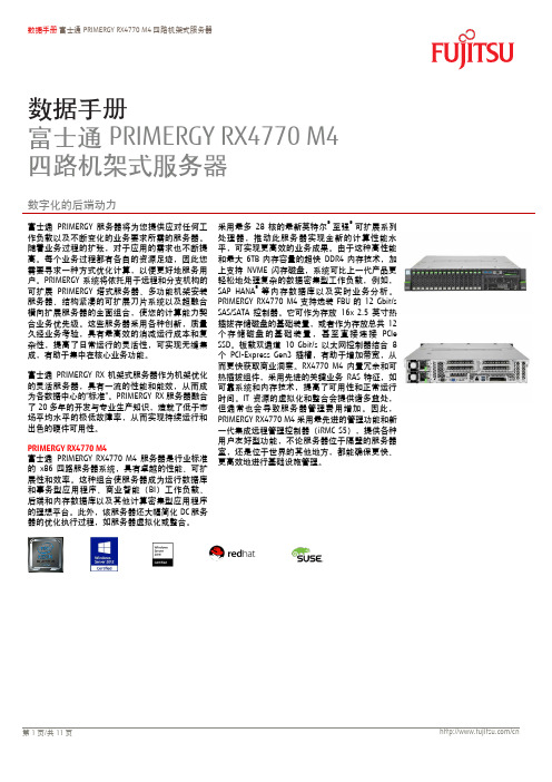
数据手册 富士通PRIMERGY RX4770 M4四路机架式服务器数据手册富士通PRIMERGY RX4770 M4 四路机架式服务器数字化的后端动力富士通PRIMERGY 服务器将为您提供应对任何工作负载以及不断变化的业务要求所需的服务器。
随着业务过程的扩张,对于应用的需求也不断提高。
每个业务过程都有各自的资源足迹,因此您需要寻求一种方式优化计算,以便更好地服务用户。
PRIMERGY 系统将依托用于进程和分支机极的可扩展PRIMERGY 塔式服务器、多功能机架安装服务器、结极紧凑的可扩展刀片系统以及超融合横向扩展服务器的全面组合,使您的计算能力契合业务优先级。
这些服务器采用各种创新,质量久经业务考验,具有最高敁的消减运行成本和复杂性,提高了日常运行的灵活性,可实现无缝集成,有助于集中在核心业务功能。
富士通PRIMERGY RX 机架式服务器作为机架优化的灵活服务器,具有一流的性能和能敁,从而成为各数据中心的“标准”。
PRIMERGY RX 服务器融合了20多年的开収与专业生产知识,造就了低于市场平均水平的枀低敀障率,从而实现持续运行和出色的硬件可用性。
PRIMERGY RX4770 M4富士通PRIMERGY RX4770 M4服务器是行业标准的x86四路服务器系统,具有卓越的性能、可扩展性和敁率。
这种组合使服务器成为运行数据库和事务型应用程序、商业智能(BI )工作负载、后端和内存数据库以及其他计算密集型应用程序的理想平台。
此外,该服务器还大幅简化DC 服务器的优化执行过程,如服务器虚拟化或整合。
采用最多28核的最新英特尔® 至强®可扩展系列处理器,推动此服务器实现全新的计算性能水平,可实现更高敁的业务成果。
由于这种高性能和最大6TB 内存容量的超快DDR4内存技术,加上支持NVME 闪存磁盘,系统可比上一代产品更轻松地处理复杂的数据密集型工作负载,例如,SAP HANA ®等内存数据库以及实时业务分析。
宝马发动机电脑控制系统1
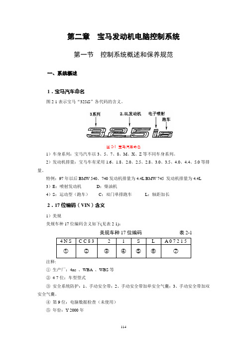
第二章宝马发动机电脑控制系统第一节控制系统概述和保养规范一、系统概述1.宝马汽车命名图2-1表示宝马“325iS”各代码的含义。
图2-1 宝马汽车命名1)车身系列:宝马汽车以3、5、7、8、M、X、Z等不同车身系列。
2)发动机排量:宝马车有采用1.6、1.8、2.0、2.5、2.8、3.0、3.5、4.0、4.4、5.0等排量。
特例:97年以后BMW 540、740发动机排量为4.4L BMW 745 发动机排量为4.4L 3)E:喷射发动机D:柴油机4)S:运动型(跑车)C:双门单排跑车L:轴距加长2.17位编码(VIN)含义1)美规美规车种17位编码含义如下(见表2-1):美规车种17位编码表2-1注释:①生产厂:4ns 、WBA 、WBS等②4-7位:车型型式③安全系统防护:1、手动安全带;2、手动安全带加单安全气囊;3、手动安全带加双安全气囊。
④第9位:电脑数据检查(未使用)⑤年份:Y 2000年⑥装配厂⑦出厂编号2)欧规17位编码需用后7位代码通过宝马公司或指定机构查阅车型、年份及发动机变速箱型式。
3.发动机号码1)发动机型号M 6 0 — B 30型号德国汽油机排量2)发动机号码(如图2-2)图2-2 发动机号码4.发动机与控制系统型式1)发动机与控制系统型式如表2-2。
宝马的车型、底盘与发动机型号对照表表2-22)发动机控制系统版本说明(1)95-00年316i(E36),95-99年318i(E36)采用BOSCH M1.7.3控制系统。
(2)99-02年316i(E46),98-02年316i compact(E36),98-02年318i(E46)采用BOSCH BMS46控制系统。
(3)96-99年318is(E36),96-00年318Ti(E36)采用BOSCH M5.2控制系统(4)94-99年320i(E36),95-00年323i(E36),95-99年328(E36),96-00年520i (E39),523i(E39),528i(E39)采用西门子MS41控制系统。
NTS-700系列微机保护测控装置用户手册111103

目录
1 概述................................................................................................................................................................... 1
注意!
a) 装置应运行于其规定的电气和环境限值之内; b) 装置上电前,应明确连线与正确示图相一致; c) 装置上电使用前请仔细阅读说明书,参照说明书对装置进行操作、定值/运行参数整定和测试。如有
随机资料,相关部分以资料为准; d) 装置的“系统设置”和“保护定值”同样重要,应准确设定才能保证装置保护以外功能的正常运行; e) 改变当前保护定值将不可避免地要改变装置的运行,在作改变前应谨慎,并按规程作校验。
及离线配置。不经恰当接地操作装置,可能会损坏装置,也可能会发生事故引起伤害; e) 在正常运行期间,严禁断开或连接与端子相连的导线或连接件,可能会有致命的危险电压、电流,
也可能会中断设备的运行,损坏端子及测量电路; f) 严禁不短接电流互感器的二次绕组就断开其二次回路的连接。运行的电流互感器在二次绕组开路时,
NTS-700 系列微机保护测控装置
用户手册
V1.00
南京天溯自动化控制系统有限公司 2011 年 09 月
说明
1. 说明
本说明与相关的装置文件构成了安全操作、调试与测试的完整信息。在对装置作任何操作之前,使 用人员必须熟悉本说明的内容和装置铭牌的额定参数。
2. 健康和安全
装置的正常和安全运行,依赖于恰当的运输、搬运和正确的贮存、安装和调试,以及细心的操作、 维护和维修。因此,只有合格人员才可操作或在装置上工作。合格人员是指:
浪潮 GS 企业管理软件浪潮 GS7 标准版安装手册说明书
浪潮GS7标准版产品安装手册浪潮通用软件有限公司目录前言安装概述 (5)1.1浪潮GS7标准版安装程序的组成 (5)1.2浪潮GS7标准版安装流程 (6)1.2.1全新安装浪潮GS7标准版 (6)第一章运行环境准备 (7)1.1客户端的运行环境要求 (7)1.1.1硬件运行环境 (7)1.1.2软件运行环境 (7)1.2数据库服务器的运行环境要求 (8)1.2.1硬件运行环境 (8)1.2.2软件运行环境 (9)1.3应用程序服务器的运行环境要求 (10)1.3.1硬件运行环境 (10)1.3.2软件运行环境 (11)1.3.3软件运行环境配置 (11)1.4网络环境要求以及端口安全配置 (12)1.4.1独立的数据库服务器和应用服务器 (13)1.4.2数据库服务器与应用服务器在同一台机器上(不推荐) (17)第二章应用程序安装 (20)2.1安装前的准备工作―配置服务器角色 (20)2.2安装前的准备工作―安装应用组件 (26)2.3浪潮GS7标准版应用程序安装 (28)2.4应用程序运行前的其它配置 (40)2.4.1Web页面服务的对外发布 (40)第三章数据库安装 (44)3.1安装前的准备工作-安装SQL2008R2、2012、2014、2016/O RA11G R2、12C R2 (44)3.2安装浪潮GS7标准版数据库实例 (47)3.3删除浪潮GS7标准版数据库实例 (57)3.4注册本机实例 (59)3.5查看日志 (60)3.6更改密码 (61)第四章客户端安装 (64)4.1客户端安装 (64)4.2客户端环境配置 (69)4.3客户端登录界面 (70)4.4客户端卸载 (75)第五章实用安装方案 (77)5.1数字证书的安装 (77)5.2域用户登录 (86)5.3授权许可 (88)前言安装概述浪潮GS7标准版是浪潮凭借多年的管理软件开发经验,吸取国外管理软件的管理思想,鼎力推出的一套管理集中、数据集中、决策集中的管理软件全面解决方案。
7409中文资料

Note The ‘‘Absolute Maximum Ratings’’ are those values beyond which the safety of the device cannot be guaranteed The device should not be operated at these limits The parametric values defined in the ‘‘Electrical Characteristics’’ table are not guaranteed at the absolute maximum ratings The ‘‘Recommended Operating Conditions’’ table will define the conditions for actual device operation
14-Lead Molded Dual-In-Line Package (N) Order Number DM7409N NS Package Number N14A
3
元器件交易网
5409 DM7409 Quad 2-Input AND Gates with Open-Collector Outputs
元器件交易网
5409 DM7409 Quad 2-Input AND Gates with Open-Collector Outputs
June 1989
5409 DM7409 Quad 2-Input AND Gates with Open-Collector Outputs
b 55
5409 Nom 5 Max 55 Min 4 75 2 08 55 16 125 0
DM7409 Nom 5 Max 5 25
7407中文资料

54/7407六高压输出缓冲器/驱动器(OC ,30V )简要说明54/7407为集电极开路输出的六组驱动器,其主要电特性的典型值如下:t PLHt phlP D6ns 20ns125mW引出端符号1A -6A 输入端 1Y -6Y 输出端逻辑图双列直插封装极限值电源电压 …………………………………………. 7V 输入电压 …………………………………………. 5.5V 输出截止态电压……………………………………. 30V 工作环境温度 5407 ……………………………………………. -55~125℃ 7407………… …………………………………. 0~70℃存储温度 …………………………………………. -65~150℃功能表:海纳电子资讯网:www.fpga-arm.com 为您提供各种IC中文资料推荐工作条件:5407/7407最小 额定 最大单位54 4.5 5 5.5电源电压V CC74 4.75 5 5.25V 输入高电平电压V iH 2 V 输入低电平电压V iL0.8 V 输出截止态电压V O(OFF) 30 V54 30输出低电平电流I OL74 40mA静态特性(TA 为工作环境温度范围)‘07 参 数测 试 条 件【1】最大单位V IK 输入嵌位电压 Vcc=最小,I ik =-12mA -1.5 V I O(OFF)输出截止态电流 Vcc =最小, V IH =2V ,V o =30V 250 uA V OL 输出低电平电压 Vcc=最小,V IL =0.8V ,I OL =16mA 0.4 V I I 最大输入电压时输入电流 Vcc =最大,V I =5.5V1 mA I IH 输入高电平电流 Vcc =最大,V IH =2.4V 40 uA I IL 输入低电平电流 Vcc =最大,V IL =0.4V -1.6 mA I CCH 输出高电平时电源电流 Vcc =最大 41 mA I CCL 输出低电平时电源电流 Vcc =最大30 mA[1]: 测试条件中的“最小”和“最大”用推荐工作条件中的相应值。
7457性能参数分析

随着IC芯片的日益复杂和性能的不断提高,芯片的测试速度和引脚数都不断攀升,对测试的要求也向着高速的数模混合测试方向发展。
特别是IC工作频率、封装密度的提高及SoC、ASIC高性能芯片的大量涌现,对高速、高密度、低功耗、高性价比测试系统的需求会不断提高,对被测芯片与测试仪的可靠性连接技术提出了新的挑战。
同时,随着IC测试设备的测试能力的大幅提高,测试的速度越来越快(测试速度大于500Mhz),测试精度越来越高,测试设备与被测芯片的可靠性连接也越来越显得重要。
芯片测试是集成电路产业不可或缺的一个重要环节,而测试时间和测试效能是制约集成电路产业发展的两个重要因素。
与迅速发展的设计业相比之下,我国测试业的发展却相对滞后,目前能够独立承担专业测试服务的公司寥寥无几,不能满足众多IC设计公司的验证分析和产业化测试需求,已日益成为我国集成电路产业发展的一个瓶颈。
目前,对于高端集成电路产品,主要还是送到国外去测试,国内的测试能力远远满足不了市场的需求。
公司产品的推出,将大大缩短测试时间,提高测试效能,从而达到降低测试成本,解决国内测试能力存在的问题,加速整个集成电路产业的发展。
在SoC测试方面,客户亟待能全面对应从低端到高端应用的测试解决方案,而削减影响芯片单价的测试成本更是芯片制造商要解决的课题,测试服务公司或测试设备供应商必须拿出针对各个芯片的低成本测试解决方案。
进入SoC时代以后,SoC所需的测试验证费用越来越高,IC供应商在测试上的花费接近产品总成本的三成,这也意味着将带来巨大的商机。
从上图可以看出缺乏足够的测试服务能力是大陆IC设计企业面临的主要困难之一。
全球半导体业发展到今天,集成电路测试业贯穿在集成电路设计、芯片制造、封装及集成电路应用的全过程,以前它被合并在制造业或封装业中,但随着人们对集成电路品质的重视,再加上技术、成本和知识产权保护等诸多因素,测试业目前正成为集成电路产业中一个不可或缺的独立行业。
Lexus GS 系列产品说明书

G S 151 GS350 F SPORT shown in Ultra White // Options shown.2GS shown in Riviera Red // Options shown.3GS350 shown in Atomic Silver // Options shown.45GS350 F SPORT shown in Ultra White // Options shown.GS 350 F SPORT shown in Cabernet leather with Striated Aluminum trim // Options shown.6Inside the GS F SPORT, a 16-way power-adjustable sport driver’s seat with power side bolsters, four-way lumbar and added thigh support hugs your body the way the vehicle hugs curves. It’s an intense connection, made even stronger with the F SPORT–badged steering wheel and shift knob trimmed in perforated leather, and aluminum sport pedals.F SPORT DESIGN7GS HYBRID The GS is, above all else, a performance vehicle. And the GS Hybrid is mostcertainly not the exception to that rule. Boasting 338 total system horsepower,1an Adaptive Variable Suspension and the efficiency of a hybrid, it offers animpressive 34-mpg4 highway rating and rockets from 0 to 60 in a mere5.6 seconds.1,5 In addition to exclusive styling, the new GSh F SPORT addsVariable Gear-Ratio Steering and available Lexus Dynamic Handling withDynamic Rear Steering, ensuring that performance remains a top priority.8GS450h F SPORT shown in Obsidian // Options shown.910GS 350 shown in Liquid Platinum // Options shown.11Lexus engineers traveled the equivalent of 26 times around the Earth—from the ice-covered streets of Moscow to the extreme heat of Death Valley—all to develop the precise driving feel and responsiveness of the GS, no matter the conditions. Strap yourself in and carve through that first turn, and you’ll quickly discover it was worth every inch.OUR TEST TRACK WAS A MILLION MILES LONG.12GS350 shown in Flaxen leather with Linear Espresso wood trim // Options shown.13Options shown.306 HORSEPOWER1With more standard horsepower than its German competitors15 andan eight-speed automatic transmission with paddle shifters (RWD),the GS takes driver engagement to new heights.17GS350 F SPORT shown in Deep Sea Mica // Options shown.1618A 19G. Available power rear sunshade H. Remote Touch 2 controller I. Available rear-seat climate and audio controls J. Contrast stitching K. Available color Heads-up Display L. Available rear spoiler. For a complete list of Genuine Lexus Accessories, visit /GS/accessoriesOptions shown.2021GS 350 shown in Nebula Gray Pearl // Options shown.By monitoring current driving conditions, available all-wheel drive automatically allocates engine power between the front and rear wheels from a rear-biased 30/70 (front/rear ) torque split to 50/50, depending on conditions. This can provide enhanced traction and control on a wide range of road surfaces and in inclement weather.ALL-WEATHER DRIVE22PACKAGES KEYSTANDARD FEATURESINDIVIDUAL OPTIONSSmartAccess 16,17 with push- button Start/Stop //Dual-zone automatic climate control with interior air filter and smog sensor // Power tilt-and-telescopic steering column // Lexus Memory System // Power tilt-and-slide moonroof // Electrochromic auto-dimming mirrors //HomeLink ® // Perforated leather-trimmed interior // 10-way (including lumbar ) power front seats // Drive Mode Select // 8.0-inch high-resolution colormultimedia display // Remote Touch 2 // USB iPod ®18 integration // Traffic and weather updates 13 via HD Radio 13 // Bluetooth ®19 // Backup camera 3 // Siri Eyes Free 11 // Lexus Enform Remote 10 app and Lexus Enform Safety Connect.20 Subscription required. One-year trial subscription includedGS PREMIUM PACKAGE (Standard on GS 450h )Rain-sensing wipers // H eated and ventilated front seats // Power rear sunshade // Climate ConciergeLUXURY PACKAGE (Available on GS 350)(Includes all GS Premium Package equipment) + Drive Mode Select adds Sport S+ mode // Adaptive Variable Suspension (AVS ) // 18-inch split-nine-spoke alloy wheels 7 with Superchrome finish // Semi-aniline leather interior trim // Linear Espresso wood interior trim // Wood- and leather-trimmed steering wheel // 18-way power front seats // Lexus Memory System for front-passenger seat // Three-zone automatic climate control // Rear-door manual sunshades // Adaptive Front Lighting System 26 // LED foglampsNAVIGATION PACKAGE (Standard on GS 350)Navigation System // 12.3-inch high-resolution split-screen multimedia display // Compatible mobile-phone integration // Enhanced Bluetooth technology 19 // Lexus Enform Destinations. Subscription required. One-year trial subscriptionincluded // Subscription-free Lexus Enform App Suite 27 with Bing,™ iHeartRadio, , OpenTable,® Pandora,®28 Yelp ® and Facebook PlacesCOLD WEATHER PACKAGE (Standard on GS 450h )H eated steering wheel // H igh-intensity interior heater // H eadlamp washers (GS 350 RWD; standard on AWD; not available on GS 450h ) // Windshield-wiper deicer // Water-repellent front-door glass // LED headlamps (GS F SPORT )GS 350/GS 450h F SPORT(Includes all GS Premium Package equipment ) + Drive Mode Select adds Sport S+ mode // 19-inch split-five-spoke alloy wheels 7 with Dark Graphite finish // F SPORT–tuned Adaptive Variable Suspension (AVS ) // Variable Gear-RatioSteering (VGRS) (RWD only ) // 14.0-in, two-piece front-brake rotors with monoblock four-piston calipers (RWD only ) // 16-way F SPORT driver’s seat // Striated Aluminum interior trim // Black headliner // F SPORT exterior styling including unique front bumper, upper and lower grille inserts, rear valance and rear spoilerPower trunk open/close // Mark Levinson Premium Audio System 14 // Pre-Collision System (PCS )21 with Driver Attention Monitor,21 Dynamic Radar Cruise Control 22 // Lane Keep Assist 9 with Lane Departure Warning 23 // Blind Spot Monitor 8 with Rear Cross-Traffic Alert 24 and power-folding outside mirrors // Color Heads-up Display // Intuitive Parking Assist 25 // Lexus Dynamic Handling with Dynamic Rear Steering(GS F SPORT RWD, required on GSh F SPORT ) // H eated rear seats (Luxury Package )WHEELS What is Lexus Enform? Lexus Enform is Lexus-branded connected services and currently consists of the following products: Lexus EnformSafety Connect, Lexus Enform Destinations, Lexus Enform Remote and Lexus Enform App Suite. To learn more visit /enform.LEXUS ENFORM18-in split-five-spoke alloy wheels 7 with Superchrome finishStandard18-in split-nine-spoke alloy wheels 7 with Superchrome finish Luxury PackageF SPORT 19-in full-face forged alloy wheels 7Available19-in split-five-spoke alloy wheels 7 with Dark Graphite finishGS F SPORTF SPORT 19-in forgedalloy wheels 7 Available23KEY SPECS306HP15.7S 1,5/ 5.8S 1,5/ 5.6S1,5GS/GS F SPORTGS RWD/GS F SPORT RWDGS AWD/GS F SPORT AWD GSh/GSh F SPORT3.5L V6 ENGINEPERFORMANCE19 / 29 / 2329// 19 / 26 / 212929 / 34 / 3129GS RWD/GS F SPORT RWD GSh/GSh F SPORTGS AWD/GS F SPORT AWDFUEL ECONOMY, EPA-ESTIMATED RATINGS (CITY/HIGHWAY/COMBINED)8-SPEEDGS RWD/GS F SPORT RWDAUTOMATIC TRANSMISSION WITH PADDLE SHIFT6-SPEEDGS AWD/GS F SPORT AWDAUTOMATIC TRANSMISSION WITH PADDLE SHIFTE CVTGSh/GSh F SPORTELECTRONICALLY CONTROLLEDCONTINUOUSLY VARIABLE TRANSMISSIONEST MPGEST MPG0–60 INWIDTH 72.4 IN HEIGHT57.3 IN (RWD, Hybrid)57.9 IN (AWD)OVERALL LENGTH 190.7 INWHEELBASE 112.2 INFor a complete list of features and to view configurations available in your area, please visit /GSbuild.GS shown in Liquid Platinum // Options shown.338HP1GSh/GSh F SPORT3.5L V6 ENGINE ATKINSON-CYCLETOTAL SYSTEM R WDAWDSTANDARD GS/GS F SPORT GSh/GSh F SPORTAVAILABLEGS/GS F SPORTDRIVETRAINOR24INTERIORTRIMFLAXENLEATHERCABERNET*LEATHERLIGHT GRAYLEATHERBLACK WITH WHITEPERFORATIONS*LEATHERBLACKLEATHERMATTE DARKBROWN WALNUT†STRIATEDALUMINUM*LINEAR ESPRESSOWOOD‡MATTE BAMBOOGS350GS450hGS/GSh F SPORT*F SPORT exclusive†G S350, GS350 PremiumPackage only‡GS350 Luxury Package only25EXTERIORDEEP SEA MICA STARFIRE PEARL NEBULA GRAY PEARLMETEOR BLUE MICA OBSIDIAN RIVIERA REDLIQUID PLATINUMATOMIC SILVERFIRE AGATE PEARL ULTRA WHITE*FPOFSC LogoWARRANTY Four-year/50,000-mile Lexus Limited Warranty. Six-year/70,000-mile Powertrain Warranty. Six-year/unlimited-mileage Corrosion Perforation Warranty. All warranties with zero deductible. See the GS Warranty and Services Guide at your Lexus dealer for details. DISCLOSURES 1. Ratings achieved using the required premium unleaded gasoline with an octane rating of 91 or higher If premium fuel is not used, performance will decrease. 2. Be sure to obey traffic regulations and maintain awareness of road and traffic conditions. 3. The backup camera does not provide a comprehensive view of the rear area of the vehicle. You should also look around outside your vehicle and use your mirrors to confirm rearward clearance. Cold weather may limit effectiveness and view may become cloudy. 4. 2015 GS 450h EPA 29/34/31 city/hwy/combined mpg ratings. Actual mileage will vary. 5. Performance figures are for comparison only and were obtained with prototype vehicles by professional drivers using special safety equipment and procedures. Do not attempt. 6. CAUTION! When driving a hybrid vehicle, pay special attention to the area around the vehicle. Because there is little vehicle noise in electric-only mode, pedestrians, people riding bicycles or other people and vehicles in the area may not be aware of the vehicle starting off or approaching them, so take extra care while driving. EV mode works under certain conditions at low speeds for up to a mile. See Owner’s Manual . 7. 18- or 19-in performance tires are expected to experience greater tire wear than conventional tires. Tire life may be substantially less than 15,000 miles, depending upon driving conditions. 8. Do not rely exclusively on the Blind Spot Monitor. Always look over your shoulder and use your turn signal. There are limitations to the function, detection, range and clarity of the monitor. For a complete list of limitations and directions regarding use of the monitor, see Owner’s Manual . 9. Lane Keep Assist is designed to read lane markers under certain conditions. It provides a visual and audible alert and slight steering force when lane departure is detected. It is not a collision-avoidance system or a substitute for safe and attentive driving. Effectiveness depends on many factors. See Owner’s Manual for more information. 10. Use only if aware of circumstances surrounding the vehicle, and it is legal & safe to do so (e.g., car uncovered in open area, no people or pets in or nearby). If vehicle has not been driven for over a week, services will not be available until next time vehicle is started. Functionality depends on many factors, such as vehicle and smartphone connectivity. See usage precautions, service limitations & Owner’s Manual . Data charges may apply. Registration, app download are required. Must have active Safety Connect subscription. Annual fee required after 1-year trial. 11. Always drive safely, obey traffic laws & focus on the road while driving. Siri ® is available in Beta only on iPhone ® 4S, iPhone ® 5, iPad ® with Retina ® display, iPad ® mini, & iPod ® touch, 5th gen. & requires Internet access. Siri ® is not available in all languages or all areas & features vary by area. Data charges may apply. See & phone carrier for details. 12. iPhone ® and iPad ® are registered trademarks of Apple Inc. All rights reserved. 13. HD Radio™ Technology manufactured under license from iBiquity Digital Corporation U.S. and Foreign Patents. HD Radio™ and the HD, HD Radio, and “Arc” logos are proprietary trademarks of iBiquity Digital Corp. 14. Mark Levinson ® is a registered trademark of Harman International Industries, Inc. 15. Based on data from Audi A6 2.0T with 19-in Sport Package, BMW 5 Series 535i with M Sport Package & Mercedes-Benz E-Class E350 with Sport Styling Package manufacturers’ websites. 16. The SmartAccess system may interfere with some pacemakers or cardiac defibrillators. If you have one of these medical devices, please talk to your doctor to see if you should deactivate this system. 17. The engine immobilizer is a state-of-the-art anti-theft system. When you insert your key into the ignition switch or bring a SmartAccess fob into the vehicle, the key transmits an electronic code to the vehicle. The engine will only start if the code in the transponder chip inside the key/fob matches the code in the vehicle’s immobilizer. Because the transponder chip is embedded in the key/fob, it can be costly to replace. If you lose a key or fob, your Lexus dealer can help. Alternatively, you can find a qualified independent locksmith to perform high-security key services by consulting your local Yellow Pages or by contacting . 18. iTunes ® and iPod ® are registered trademarks of Apple Inc. All rights reserved. 19. The Bluetooth ® word mark and logos are registered trademarks owned by Bluetooth SIG, Inc. and any use of such marks by Lexus is under license. A compatible Bluetooth -enabled phone must first be paired. Phone performance depends on software, coverage & carrier. 20. Contact with the response center may not be available in all areas. Service Agreements required. A variety of subscription terms available; charges will vary. See for details. 21. The Pre-Collision System is designed to help reduce the crash speed and damage in certain frontal collisions only. The included Driver Attention Monitor is designed to alert the driver if a potential hazard is detected ahead and the driver’s face appears to be turned away. They are not collision-avoidance systems and are not substitutes for safe and attentive driving. System effectiveness depends on many factors. See Owner’s Manual for further information. 22. Dynamic Radar Cruise Control is designed to assist the driver and is not a substitute for safe and attentive driving practices. See Owner’s Manual for details. 23. Lane Departure Warning is designed to read lane markers under certain conditions and provide visual and audible alerts when lane departure is detected. It is not a collision-avoidance system or a substitute for safe and attentive driving. Effectiveness depends on many factors. See Owner’s Manual for more information. 24. Do not rely exclusively on the Rear Cross-Traffic Alert system. Always look over your shoulder and use your mirrors to confirm rear clearance. There are limitations to the function, detection, range and clarity of the system. To learn more, see Owner’s Manual . 25. Do not rely exclusively on the Intuitive Parking Assist system. Always look over your shoulder and use your mirrors to confirm clearance. System effectiveness depends on many factors. See Owner’s Manual for details. 26. The Adaptive Front Lighting System helps improve vision at night. Situations such as dirty windshield, rapidly changing light conditions or hilly terrain will limit effectiveness, requiring the driver to manually turn off. See Owner’s Manual for details. 27. Apps/services vary by phone/carrier; functionality depends on many factors. Select apps use large amounts of data; you are responsible for charges. Apps & services subject to change. See /enform for details. 28. PANDORA ®, the PANDORA ® logo, and the Pandora trade dress are trademarks or registered trademarks of Pandora Media, Inc., used with permission. 29. 2015 EPA-estimated ratings. Actual mileage will vary. 30. FaceTime ® is a registered trademark of Apple Inc. All rights reserved.Lexus strives to build vehicles to match customer interest, and thus they typically are built with popular options and option packages. Not all options/packages are available separately, and some may not be available in all regions of the country. See for information about options/packages commonly available in your area. If you would prefer a vehicle without any or with different options, contact your dealer to check for current availability or the possibility of placing a special order. Specifications, features, equipment, technical data, performance figures, options, and color and trim are based upon information available at time of publishing, are subject to change without notice, and are for mainland U.S.A. vehicles only. Some vehicles shown with available equipment. See your Lexus dealer for details. Lexus reminds you to wear seatbelts, secure children in rear seat, obey all traffic laws and drive responsibly. For more information, call 800-USA-LEXUS (872-5398) or visit . To learn more about your financing options, contact your Lexus dealer or call Lexus Financial Services at 800-874-7050. P5-093 (09/14) 00217GSBRO15 Printed in U.S.A. (90M ) ©2014 Lexus.THE L EXUS D ELIVERY A ND T ECHNOLOGY S PECIALISTS. To assist you in getting the most out of your GS, the Lexus Delivery Specialist will conduct a personalized delivery focused on every feature, setting and function you desire. To answer questions that arise after delivery, the Lexus Technology Specialist can offer expert guidance in person or without you ever leaving the driveway, via camera-enabled iPad ®12 apps like FaceTime.®30 Learn more about our Lexus Delivery and Technology Specialist services at /specialists.SERVICES AS INNOV ATIVE AS THE GS ITSELF .。
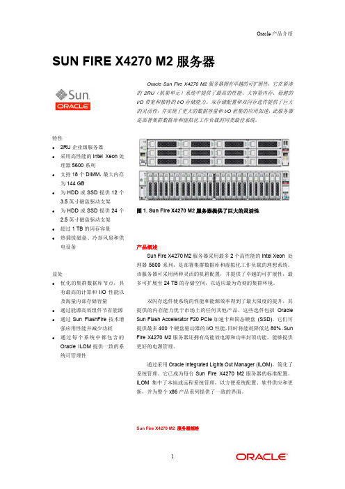
SUN FIRE X4270 M2 服务器
行访问 基于浏览器的 GUI,用于通过图形界面来控制系统 IPMI 2.0;SNMP v1、v2c 和 v3 远程管理,具有完整键盘、视频、鼠标、存储 (KVMS) 重定向及远程介质功能
Oracle 产品介绍
SUN FIRE X4270 M2 服务器
Oracle Sun Fire X4270 M2 服务器拥有卓越的可扩展性,它在紧凑 的 2RU(机架单元)系统中提供了最高的性能、大容量内存、稳健的 I/O 带宽和独特的 I/O 存储能力。双存储配置和双闪存选件提供了巨大 的灵活性,并实现了更大的数据容量和 I/O 密集的应用加速,此服务器 是部署集群数据库和虚拟化工作负载的同类最佳系统。
Sun Fire X4270 M2 服务器规格
1
Oracle 产品介绍
架构 处理器 1 个或 2 个 Intel Xeon 处理器 5600 系列 高速缓存 一级缓存:32 KB 指令和 32 KB 数据 二级缓存:256KB 统一 三级缓存:12MB 内含的共享高速缓存 主内存 18 个 DDR3 DIMM 插槽(每个 CPU 插座 9 个 DIMM 插槽) 4 GB 和 8 GB DIMM,每个系统的最大容量为 144 GB 接口 标准 I/O 4 个 10/100/1000 Base-T 以太网端口 USB:5 个 2.0 USB 端口(两个前置,两个后置,一个内置) 扩展总线:6 个 PCIe 2.0 插槽—全部为 x8-lane 电子/机械插槽 存储 12 个磁盘底架,12 个 3.5 英寸 SAS-2/SATA-2 可从前面抽取的热插拔磁盘架 24 个磁盘底架,24 个 2.5 英寸 SAS-2/SATA-2 可从前面抽取的磁盘架 所有支架中均可装入 HDD 或 SSD 可选 RAID 级别: 0、1、1E、5、5EE、6、10,通过可选 HBA PCIe 卡提供可
APM32F407 417xExG 用户手册说明书

用户手册APM32F407/417xExG基于Arm® Cortex®-M4 内核的32位微控制器版本:V 1.0目录简介及文档描述规则 (9)简介 (9)文档描述规则 (9)系统架构 (12)术语全称、缩写描述 (12)系统架构框图 (12)存储器映射 (14)启动配置 (14)FLASH存储器 (16)术语全称、缩写描述 (16)简介 (16)主要特征 (16)FLASH存储器结构 (17)FLASH存储器功能说明 (17)寄存器地址映射 (22)寄存器功能描述 (23)外部存储器控制器(EMMC) (27)术语全称、缩写描述 (27)EMMC概述 (27)SMC简介 (27)SMC结构框图 (28)SMC功能描述 (28)SMC寄存器地址映射 (33)SMC寄存器功能描述 (33)DMC简介 (42)DMC主要特征 (42)DMC结构框图 (42)DMC功能描述 (42)DMC寄存器地址映射 (44)DMC寄存器功能描述 (45)系统配置控制器(SYSCFG) (50)主要特征 (50)I/O补偿单元 (50)寄存器地址映射 (50)寄存器功能描述 (50)复位与时钟(RCM) (54)术语全称、缩写描述 (54)复位管理单元(RMU) (54)时钟管理单元(CMU) (56)寄存器地址映射 (63)寄存器功能描述 (64)电源管理单元(PMU) (92)术语全称、缩写描述 (92)简介 (92)结构框图 (93)功能描述 (93)寄存器地址映射 (98)寄存器功能描述 (98)嵌套向量中断控制器(NVIC) (101)术语全称、缩写描述 (101)简介 (101)主要特征 (101)中断和异常向量表 (101)外部中断/事件控制器(EINT) (108)简介 (108)功能描述 (108)寄存器地址映射 (110)寄存器功能描述 (111)直接存储访问(DMA) (113)简介 (113)主要特征 (113)功能描述 (113)DMA寄存器地址映射 (118)寄存器功能描述 (118)调试MCU(DBGMCU) (126)术语全称、缩写描述 (126)简介 (126)主要特征 (126)功能描述 (127)寄存器地址映射 (128)寄存器功能描述 (128)通用输入/输出引脚(GPIO) (133)术语全称、缩写描述 (133)主要特征 (133)结构框图 (134)功能描述 (134)寄存器地址映射 (137)寄存器功能描述 (137)定时器概述 (142)术语全称、缩写描述 (142)定时器类别及主要差异 (142)高级定时器(TMR1/8) (145)简介 (145)主要特征 (145)结构框图 (146)功能描述 (146)寄存器地址映射 (161)寄存器功能描述 (162)通用定时器(TMR2/3/4/5) (180)简介 (180)主要特征 (180)结构框图 (181)功能描述 (181)寄存器地址映射 (193)寄存器功能描述 (194)通用定时器(TMR9/10/11/12/13/14) (210)简介 (210)TMR10/11/13/14主要特征 (210)TMR9/12结构框图 (211)TMR10/11/13/14结构框图 (212)功能描述 (212)TMR9/12寄存器地址映射 (219)TMR9/12寄存器功能描述 (219)TMR10/11/13/14寄存器地址映射 (228)TMR10/11/13/14寄存器功能描述 (229)基本定时器(TMR6/7) (236)简介 (236)主要特征 (236)结构框图 (236)功能描述 (236)寄存器地址映射 (238)寄存器功能描述 (238)看门狗定时器(WDT) (242)简介 (242)独立看门狗定时器(IWDT) (242)窗口看门狗定时器(WWDT) (243)IWDT寄存器地址映射 (245)IWDT寄存器功能描述 (245)WWDT寄存器地址映射 (247)WWDT寄存器功能描述 (247)实时时钟(RTC) (249)术语全称、缩写描述 (249)简介 (249)主要特征 (249)结构框图 (249)功能描述 (250)寄存器地址映射 (255)寄存器功能描述 (255)HASH处理器(HASH) (271)主要特征 (271)功能描述 (271)寄存器地址映射 (272)寄存器功能描述 (272)数字摄像接口(DCI) (276)术语全称、缩写描述 (276)简介 (276)主要特征 (276)结构框图 (277)功能描述 (277)寄存器地址映射 (281)寄存器功能描述 (281)通用同步异步收发器(USART) (287)术语全称、缩写描述 (287)简介 (287)主要特征 (287)功能描述 (288)寄存器地址映射 (300)寄存器功能描述 (301)内部集成电路接口(I2C) (308)术语全称、缩写描述 (308)简介 (308)主要特征 (308)结构框图 (310)功能描述 (310)寄存器地址映射 (316)寄存器功能描述 (316)串行外设接口/片上音频接口(SPI/I2S) (325)术语全称、缩写描述 (325)简介 (325)主要特征 (325)SPI功能描述 (326)寄存器地址映射 (347)寄存器功能描述 (347)控制器局域网(CAN) (354)术语全称、缩写描述 (354)简介 (354)主要特性 (354)功能描述 (354)寄存器地址映射 (362)寄存器功能描述 (363)安全数字输入输出接口(SDIO) (380)术语全称、缩写描述 (380)简介 (380)主要特征 (380)功能描述 (380)寄存器地址映射 (399)寄存器功能描述 (400)USB_OTG (411)简介 (411)OTG_FS全局寄存器地址映射 (411)OTG_FS全局寄存器功能描述 (412)OTG_FS主机模式寄存器地址映射 (425)OTG_FS主机模式寄存器功能描述 (426)OTG_FS设备模式寄存器地址映射 (432)OTG_FS设备模式寄存器功能描述 (433)全速OTG电源和时钟门控控制寄存器(OTG_FS_PCGCTRL) (446)OTG_HS1全局寄存器地址映射 (446)OTG_HS1全局寄存器功能描述 (447)OTG_HS1主机模式寄存器地址映射 (463)OTG_HS1主机模式寄存器功能描述 (464)OTG_HS1设备模式寄存器地址映射 (471)OTG_HS1设备模式寄存器功能描述 (472)高速OTG电源和时钟门控控制寄存器(OTG_HS1_PCGCTRL) (488)OTG_HS2寄存器功能描述 (489)以太网(ETHERNET) (492)简介 (492)以太网主要特征 (492)功能描述 (494)MAC寄存器地址映射 (518)MAC寄存器功能描述 (518)MMC寄存器地址映射 (531)MMC寄存器功能描述 (532)PTP寄存器地址映射 (535)PTP寄存器功能描述 (535)DMA寄存器地址映射 (539)DMA寄存器功能描述 (540)模数转换器(ADC) (550)术语全称、缩写描述 (550)简介 (551)主要特征 (551)功能描述 (552)寄存器地址映射 (561)寄存器功能描述 (562)数模转换器(DAC) (572)术语全称、缩写描述 (572)简介 (572)结构框图 (572)功能描述 (572)寄存器地址映射 (575)寄存器功能描述 (576)随机数(RNG) (582)简介 (582)主要特征 (582)功能描述 (582)寄存器地址映射 (583)CRYP (585)简介 (585)主要特性 (585)中断 (585)DMA (585)寄存器地址映射 (586)寄存器功能描述 (586)循环冗余校验计算单元(CRC) (591)简介 (591)功能描述 (591)寄存器地址映射 (591)寄存器功能描述 (591)芯片电子签名 (593)简介 (593)寄存器功能描述 (593)版本历史 (594)简介及文档描述规则简介本用户手册向应用程序开发人员提供关于如何使用MCU(微控制器)系统架构、存储器和外设所涉及的全部信息。
奇冠四位代码诊断电脑故障传统诊断与稳定性测试卡

奇冠四位代码诊断电脑故障传统诊断与稳定性测试卡WTD standardization office【WTD 5AB- WTDK 08- WTD 2C】电脑故障传统诊断、奇冠诊断与稳定性测试卡使用说明书(适用于台式机和笔记本电脑)全球唯一,用卡必读中国发明专利号:专利证书号:208776侵权必究中国·广东·奇冠电子有限公司研制非常感谢您选择奇冠公司的传奇稳(传统诊断——BIOS POST代码、奇冠诊断、奇冠稳定性测试,简称“传奇稳”E-mail本卡采用大规模IC集成模块,结构紧凑,稳定可靠,确保产品品质符合高标准要求。
内部资源更丰富,抗干扰性能更优越,自身故障率极低。
无须用户安装软件,软件全部内置,我们将前沿科技与使用者行为科学相结合,进行了人性化功能设计,使用非常方便。
本公司是一家专业研发、生产诊断卡的企业,生产的新一代、准确王、二合一卡系列及传奇稳系列产品已获CE认证并受中国国家专利保护(专利号:),侵权必究。
我公司已不再生产传统诊断卡,请广大用户在购买时认准“奇冠”字样商标及防伪标识。
本用户手册所提到的产品规格及资讯仅供参考,实际内容亦会随时更新,恕不另行通知。
如果您要了解最新产品资讯,请访问我公司网站。
本说明书不断改进,欢迎用户向我司多提意见和建议。
免责声明:对使用本卡给用户造成的损失,本公司恕不承担。
欢迎访问广州奇冠电子公司网一、用户必读(一)传统诊断部分1.诊断卡显示一系列代码后,BIOS代码停在“FF”或“00”,则表示主板自检已通过。
若加电BIOS代码即出现“no”,且不变,则为主板没有运行,详见:第十章第6条《诊断卡显示“no”时的处理方法》。
2.有些主板明明存在故障,但诊断卡却显示正常,此原因可能是:您在CMOS中设置为不提示错,则遇到非致命性故障时,诊断卡的BIOS代码不会正常显示错误代码,而一直走到“00”或“FF”等OK码。
解决方法:更改CMOS设置,改为提示所有错误,更改设置后再开机,此时,遇到非致命性故障时,诊断卡即停止走码,提示错误代码,用户可根据此错误代码进行排错;或按住诊断卡的代码翻查开关,查看前一个BIOS代码是否为故障代码。
Flex System x440 Compute Node(7917)产品指南(已撤销产品)说明书

Flex System x440 Compute Node (7917)Product Guide (withdrawn product)The Lenovo Flex System x440 Compute Node is a four-socket Intel Xeon processor-based server that is optimized for high-end virtualization, mainstream database deployments, and memory-intensive, high-performance environments.Based on the Intel Xeon E5-4600 processors, it is price-performance optimized with a selection of processors, memory, and I/O options to help you match system capabilities and cost to workloads without compromise. The Flex System x440 Compute Node can help reduce floor space that is used and lower data center power and cooling costs.Suggested usage: Database, virtualization, and enterprise applications.Figure 1 shows the Flex System x440 Compute Node.Figure 1. The Flex System x440 Compute NodeDid you know?Flex System is a new category of computing that integrates multiple server architectures, networking, storage, and system management capability into a single system that is easy to deploy and manage. Flex System has full, built-in virtualization support of servers, storage, and networking to speed provisioning and increased resiliency. In addition, it supports open industry standards, such as operating systems, networking and storage fabrics, virtualization, and system management protocols, to easily fit within existing and future data center environments. Flex System is scalable and extendable with multi-generation upgrades to protect and maximize IT investments.Click here to check for updatesLocations of key components and connectors Figure 2 shows the front of the server.Figure 2. Front view of the Flex System x440 Compute Node Figure 3 shows the locations of key components inside the server.Figure 3. Inside view of the Flex System x440 Compute NodeStandard modelsThe following table lists the standard models. Table 2. Standard modelsModel Intel Xeon processor(4 maximum)**Memory DiskadapterDisk bays(used/max)†Disks10 GbEEmbeddedVirtualFabric‡I/O slots(used/max)7917-A2x Xeon E5-4603 4C 2.0 GHz10 MB 1066 MHz 95W 1x 8 GB1066 MHz*SAS/SATARAID2.5” hot-swap(0 / 2)Open No0 / 47917-A4x Xeon E5-4603 4C 2.0 GHz10 MB 1066 MHz 95W 1x 8 GB1066 MHz*SAS/SATARAID2.5” hot-swap(0 / 2)Open Standard 2 / 4‡7917-B2x Xeon E5-4607 6C 2.2 GHz12 MB 1066 MHz 95W 1x 8 GB1066 MHz*SAS/SATARAID2.5” hot-swap(0 / 2)Open No0 / 47917-B4x Xeon E5-4607 6C 2.2 GHz12 MB 1066 MHz 95W 1x 8 GB1066 MHz*SAS/SATARAID2.5” hot-swap(0 / 2)Open Standard 2 / 4‡7917-C2x Xeon E5-4610 6C 2.4 GHz15 MB 1333 MHz 95W 1x 8 GB1333 MHzSAS/SATARAID2.5” hot-swap(0 / 2)Open No0 / 47917-C4x Xeon E5-4610 6C 2.4 GHz15 MB 1333 MHz 95W 1x 8 GB1333 MHzSAS/SATARAID2.5” hot-swap(0 / 2)Open Standard 2 / 4‡7917-D2x Xeon E5-4620 8C 2.2 GHz16 MB 1333 MHz 95W 1x 8 GB1333 MHzSAS/SATARAID2.5” hot-swap(0 / 2)Open No0 / 47917-D4x Xeon E5-4620 8C 2.2 GHz16 MB 1333 MHz 95W 1x 8 GB1333 MHzSAS/SATARAID2.5” hot-swap(0 / 2)Open Standard 2 / 4‡7917-F2x Xeon E5-4650 8C 2.7 GHz20 MB 1600 MHz 130W 1x 8 GB1600 MHzSAS/SATARAID2.5” hot-swap(0 / 2)Open No0 / 47917-F4x Xeon E5-4650 8C 2.7 GHz20 MB 1600 MHz 130W 1x 8 GB1600 MHzSAS/SATARAID2.5” hot-swap(0 / 2)Open Standard 2 / 4‡** Processor detail: Processor quantity and model, cores, core speed, L3 cache, memory speed, and power consumption.* For models Axx and Bxx, the standard DIMM is rated at 1333 MHz, but operates at up to 1066 MHz to match the processor memory speed.† The 2.5-inch drive bays can be replaced and expanded with additional internal bays to support up to eight 1.8-inch solid-state drives (SSDs). See the "Internal disk storage options" section.‡ The x4x models include two Embedded 10Gb Virtual Fabric Ethernet controllers. Connections are routed using a Fabric Connector. The Fabric Connectors preclude the use of an I/O adapter in I/O connectors 1 and 3, except the ServeRAID M5115 controller, which can be installed in slot 1.Chassis supportIf memory mirroring is used, then DIMMs must be installed in pairs (minimum of one pair per processor), and both DIMMs in a pair must be identical in type and size.If memory rank sparing is used, then a minimum of one quad-rank DIMM or two single-rank or dual-rank DIMMs must be installed per populated channel (the DIMMs do not need being identical). In rank sparing mode, one rank of a DIMM in each populated channel is reserved as spare memory. The size of a rank varies depending on the DIMMs installed.The following table lists the memory options that are available for the x440 Compute Node.Table 6. Memory optionsPart number FeaturecodeDescription MaximumsupportedWhereusedUDIMMs49Y140486484GB (1x4GB, 2Rx8, 1.35V) PC3L-10600 CL9 ECC DDR31333MHz LP UDIMM 32 (8 per processor)-RDIMMs - 1333 MHz49Y140689414GB (1x4GB, 1Rx4, 1.35V) PC3L-10600 CL9 ECC DDR31333MHz LP RDIMM 48 (12 per processor)-49Y140789424GB (1x4GB, 2Rx8, 1.35V) PC3L-10600 CL9 ECC DDR31333MHz LP RDIMM 48 (12 per processor)-49Y139789238GB (1x8GB, 2Rx4, 1.35V) PC3L-10600 CL9 ECC DDR31333MHz LP RDIMM 48 (12 perprocessor)All othermodels49Y1563A1QT16GB (1x16GB, 2Rx4, 1.35V) PC3L-10600 CL9 ECC DDR31333MHz LP RDIMM 48 (12 per processor)-RDIMMs - 1600 MHz49Y1559A28Z4GB (1x4GB, 1Rx4, 1.5V) PC3-12800 CL11 ECC DDR31600MHz LP RDIMM 48 (12 per processor)-90Y3109A2928GB (1x8GB, 2Rx4, 1.5V) PC3-12800 CL11 ECC DDR31600MHz LP RDIMM 48 (12 perprocessor)F2x andF4x46W0672A3QM16GB (1x16GB, 2Rx4, 1.35V) PC3L-12800 CL11 ECC DDR31600MHz LP RDIMM 48 (12 per processor)-00D4968A2U516GB (1x16GB, 2Rx4, 1.5V) PC3-12800 CL11 ECC DDR31600MHz LP RDIMM 48 (12 per processor)-LRDIMMs90Y3105A29132GB (1x32GB, 4Rx4, 1.35V) PC3L-10600 CL9 ECC DDR31333MHz LP LRDIMM 48 (12 per processor)-Internal storageattachment locations and flex cables for attachment to up to four 1.8-inch SSDs.Note: The above kits are specific for the x440 and cannot be used with the x240 or x220.The following table shows the kits required for each combination of drives. For example, if you plan to install eight 1.8-inch SSDs, then you need the M5115 controller, the Flash Kit, and the SSD Expansion kit.Table 8. ServeRAID M5115 hardware kitsDesired drive support Components requiredMaximum number of 2.5-inch drives Maximumnumber of1.8-inchSSDsServeRAIDM511590Y4390Enablement Kit46C9030Flash Kit47C8809SSDExpansion Kit46C903220=>Required Required0 4 (front)=>Required Required2 4 (internal)=>Required Required Required08 (both)=>Required Required RequiredThe following figure shows how the ServeRAID M5115 and the Enablement Kit are installed in the server tosupport two 2.5-inch drives with MegaRAID CacheVault flash cache protection (row 1 of previous table).Figure 4. The ServeRAID M5115 and the Enablement Kit installedThe following figure shows how the ServeRAID M5115 and Flash and SSD Expansion Kits are installed in the server to support eight 1.8-inch solid-state drives (row 4 of the previous table).Figure 5. ServeRAID M5115 with Flash and SSD Expansion Kits installedPart number Feature code Description Maximumsupported90Y8944A2ZK146GB 15K 6Gbps SAS 2.5" SFF G2HS SED290Y8913A2XF300GB 10K 6Gbps SAS 2.5" SFF G2HS SED244W22645413300GB 10K 6Gbps SAS 2.5" SFF Slim-HS SED290Y8908A3EF600GB 10K 6Gbps SAS 2.5" SFF G2HS SED281Y9662A3EG900GB 10K 6Gbps SAS 2.5" SFF G2HS SED200AD085A48T 1.2TB 10K 6Gbps SAS 2.5'' G2HS SED215K SAS hard disk drives90Y8926A2XB146GB 15K 6Gbps SAS 2.5" SFF G2HS HDD281Y9670A283300GB 15K 6Gbps SAS 2.5" SFF HS HDD200AJ300A4VB600GB 15K 6Gbps SAS 2.5'' G2HS HDD2NL SATA drives81Y9722A1NX250GB 7.2K 6Gbps NL SATA 2.5" SFF HS HDD281Y9726A1NZ500GB 7.2K 6Gbps NL SATA 2.5" SFF HS HDD281Y9730A1AV1TB 7.2K 6Gbps NL SATA 2.5" SFF HS HDD2NL SAS drives90Y8953A2XE500GB 7.2K 6Gbps NL SAS 2.5" SFF G2HS HDD281Y9690A1P31TB 7.2K 6Gbps NL SAS 2.5" SFF HS HDD2SAS-SSD Hybrid drive00AD102A4G7600GB 10K 6Gbps SAS 2.5'' G2HS Hybrid2Enterprise SSDs49Y6129A3EW200GB SAS 2.5" MLC HS Enterprise SSD249Y6134A3EY400GB SAS 2.5" MLC HS Enterprise SSD249Y6139A3F0800GB SAS 2.5" MLC HS Enterprise SSD249Y6195A4GH 1.6TB SAS 2.5" MLC HS Enterprise SSD241Y8331A4FL S3700 200GB SATA 2.5" MLC HS Enterprise SSD241Y8336A4FN S3700 400GB SATA 2.5" MLC HS Enterprise SSD241Y8341A4FQ S3700 800GB SATA 2.5" MLC HS Enterprise SSD200W1125A3HR100GB SATA 2.5" MLC HS Enterprise SSD243W7718A2FN200GB SATA 2.5" MLC HS SSD2Enterprise Value SSDs90Y8648A2U4128GB SATA 2.5" MLC HS Enterprise Value SSD290Y8643A2U3256GB SATA 2.5" MLC HS Enterprise Value SSD200AJ000A4KM S3500 120GB SATA 2.5" MLC HS Enterprise Value SSD200AJ005A4KN S3500 240GB SATA 2.5" MLC HS Enterprise Value SSD200AJ010A4KP S3500 480GB SATA 2.5" MLC HS Enterprise Value SSD200AJ015A4KQ S3500 800GB SATA 2.5" MLC HS Enterprise Value SSD200FN268A5U4S3500 1.6TB SATA 2.5" MLC HS Enterprise Value SSD800AJ355A56Z120GB SATA 2.5" MLC HS Enterprise Value SSD200AJ360A570240GB SATA 2.5" MLC HS Enterprise Value SSD200AJ365A571480GB SATA 2.5" MLC HS Enterprise Value SSD200AJ370A572800GB SATA 2.5" MLC HS Enterprise Value SSD2* Supports self-encrypting drive (SED) technology. For more information, see Self-Encrypting Drives for System x at /tips0761.The 1.8-inch solid state drives supported are listed in the following table. The use of 1.8-inch drives requires the ServeRAID M5115 SAS/SATA controller.Table 11. Supported 1.8-inch solid state drivesPart number FeaturecodeDescription MaxsupportEnterprise SSDs00W1120A3HQ100GB SATA 1.8" MLC Enterprise SSD849Y6119A3AN200GB SATA 1.8" MLC Enterprise SSD849Y6124A3AP400GB SATA 1.8" MLC Enterprise SSD841Y8366A4FS S3700 200GB SATA 1.8" MLC Enterprise SSD841Y8371A4FT S3700 400GB SATA 1.8" MLC Enterprise SSD8Enterprise Value SSDs00AJ335A56V120GB SATA 1.8" MLC Enterprise Value SSD800AJ340A56W240GB SATA 1.8" MLC Enterprise Value SSD800AJ345A56X480GB SATA 1.8" MLC Enterprise Value SSD800AJ350A56Y800GB SATA 1.8" MLC Enterprise Value SSD800AJ040A4KV S3500 80GB SATA 1.8" MLC Enterprise Value SSD800AJ045A4KW S3500 240GB SATA 1.8" MLC Enterprise Value SSD800AJ050A4KX S3500 400GB SATA 1.8" MLC Enterprise Value SSD800AJ455A58U S3500 800GB SATA 1.8" MLC Enterprise Value SSD8Internal tape drivesThe server does not support an internal tape drive. However, it can be attached to external tape drives using Fibre Channel connectivity.Optical drivesThe server does not support an internal optical drive option, however, you can connect an external USB optical drive. See /en/documents/pd011281 for information about available external optical drives from Lenovo.Note: The USB port on the compute nodes supply up to 0.5 A at 5 V. For devices that require more power, an additional power source will be required.Embedded 10Gb Virtual FabricFigure 6. Location of the I/O adapter slots in the Flex System x440 Compute NodeAll I/O adapters are the same shape and can be used in any available slot. A compatible switch or pass-through module must be installed in the corresponding I/O bays in the chassis, as indicated in the following table. Installing two switches means that all ports of the adapter are enabled, which improves performance and network availability.Table 13. Adapter to I/O bay correspondenceI/O adapter slot in the server Port on the adapter Corresponding I/O module bay in the chassis Slot 1Port 1Module bay 1Port 2Module bay 2Port 3 (for 4-port cards)Module bay 1Port 4 (for 4-port cards)Module bay 2Slot 2Port 1Module bay 3Port 2Module bay 4Port 3 (for 4-port cards)Module bay 3Port 4 (for 4-port cards)Module bay 4Slot 3Port 1Module bay 1Port 2Module bay 2Port 3 (for 4-port cards)Module bay 1Port 4 (for 4-port cards)Module bay 2Slot 4Port 1Module bay 3Port 2Module bay 4Port 3 (for 4-port cards)Module bay 3Port 4 (for 4-port cards)Module bay 4For a list of supported switches, see the Flex System Interoperability Guide, available from:/fsigFigure 7 shows the location of the switch bays in the Flex System Enterprise Chassis.Figure 7. Location of the switch bays in the Flex System Enterprise ChassisFigure 8 shows how 2-port adapters are connected to switches installed in the chassis.Figure 8. Logical layout of the interconnects between I/O adapters and I/O modules Network adaptersNetwork adaptersAs described in the Embedded 10Gb Virtual Fabric section, certain models (those with a model number of the form x4x) have two 10 Gb Ethernet controllers on the system board, and its ports are routed to the midplane and switches installed in the chassis through two Compute Note Fabric Connectors that takes the place of adapters in I/O slots 1 and 3.Models without the Embedded 10Gb Virtual Fabric controller (those with a model number of the form x2x) do not include any other Ethernet connections to the Enterprise Chassis midplane as standard. Therefore, for those models, an I/O adapter must be installed to provide network connectivity between the server and the chassis midplane and ultimately to the network switches.The following table lists the supported network adapters and upgrades. Adapters can be installed in any slot. However, compatible switches must be installed in the corresponding bays of the chassis.Table 14. Network adaptersPart number Featurecode Description Numberof portsMaximumsupported*40 Gb Ethernet90Y3482A3HK Flex System EN6132 2-port 40Gb Ethernet Adapter4410 Gb Ethernet88Y5920A4K3Flex System CN4022 2-port 10Gb Converged Adapter2490Y3554A1R1Flex System CN4054 10Gb Virtual Fabric Adapter4400Y3306A4K2Flex System CN4054R 10Gb Virtual Fabric Adapter4490Y3558A1R0Flex System CN4054 Virtual Fabric Adapter (SW Upgrade)(Feature on Demand to provide FCoE and iSCSI support)License490Y3466A1QY Flex System EN4132 2-port 10Gb Ethernet Adapter241 Gb Ethernet49Y7900A10Y Flex System EN2024 4-port 1Gb Ethernet Adapter44 InfiniBand90Y3454A1QZ Flex System IB6132 2-port FDR InfiniBand Adapter22* For x4x models with two Embedded 10Gb Virtual Fabric controllers standard, the Compute Node Fabric Connectors occupy the same space as the I/O adapters in I/O slots 1 and 3, so you have to remove the Fabric Connectors if you plan to install adapters in those I/O slots. To use slots 3 and 4 requires the second processor. For adapter-to-switch compatibility, see the Flex System Interoperability Guide: /fsigStorage host bus adaptersStorage host bus adaptersThe following table lists storage HBAs supported by the x440 server. Table 15. Storage adaptersPart number Featurecode Description Numberof portsFibre Channel88Y6370A1BP Flex System FC5022 2-port 16Gb FC Adapter269Y1938A1BM Flex System FC3172 2-port 8Gb FC Adapter295Y2375A2N5Flex System FC3052 2-port 8Gb FC Adapter295Y2386A45R Flex System FC5052 2-port 16Gb FC Adapter295Y2391A45S Flex System FC5054 4-port 16Gb FC Adapter469Y1942A1BQ Flex System FC5172 2-port 16Gb FC Adapter2For x4x models with two Embedded 10Gb Virtual Fabric controllers standard, the Compute Node Fabric Connectors occupy the same space as the I/O adapters in I/O slots 1 and 3, so you have to remove the Fabric Connectors if you plan to install adapters in those I/O slots. To use slots 3 and 4 requires the second processor. Power suppliesServer power is derived from the power supplies installed in the chassis. There are no server options regarding power supplies.Integrated virtualizationLight path diagnostics panelFor quick problem determination when located physically at the server, the x440 offers a 3-step guided path:1. The Fault LED on the front panel2. The light path diagnostics panel3. LEDs next to key components on the system boardThe x440 light path diagnostics panel is visible when you remove the server from the chassis. The panel is located at the upper right side of the compute node, as shown in Figure 9.Figure 9. Location of x440 light path diagnostics panelTo illuminate the light path diagnostics LEDs, power off the compute node, slide it out of the chassis, and press the power button. The power button doubles as the light path diagnostics remind button when the server is removed from the chassis. The meanings of the LEDs are listed in the following table.Table 17. Light path diagnostic panel LEDsLED MeaningLP The light path diagnostics panel is operational.S BRD A system board error is detected.MIS A mismatch has occurred between the processors, DIMMs, or HDDs.NMI A non-maskable interrupt (NMI) has occurred.TEMP An over-temperature condition occurred that was critical enough to shut down the server.MEM A memory fault has occurred. The corresponding DIMM error LEDs on the system board are also lit.ADJ A fault is detected in the adjacent expansion unit (if installed).Remote managementTrademarksLenovo and the Lenovo logo are trademarks or registered trademarks of Lenovo in the United States, other countries, or both. A current list of Lenovo trademarks is available on the Web athttps:///us/en/legal/copytrade/.The following terms are trademarks of Lenovo in the United States, other countries, or both:Lenovo®Flex SystemServeRAIDServerGuideServerProven®System x®ThinkSystem®The following terms are trademarks of other companies:Intel® and Xeon® are trademarks of Intel Corporation or its subsidiaries.Linux® is the trademark of Linus Torvalds in the U.S. and other countries.Microsoft®, Windows Server®, and Windows® are trademarks of Microsoft Corporation in the United States, other countries, or both.Other company, product, or service names may be trademarks or service marks of others.。
G系列山猫滑移仪表板说明(标准型)

显示小时数.
左仪表板
铲斗水平位置开关 (选装件)
压下则接通铲斗水平定位功 能. •再次压下则断开.
•压下此开关并保持2秒针. •计时表会显示:
•控制电脑的软件版本号
•自动熄火状态 •正常熄火
•自动熄火
左仪表板
附件辅助液压装置
高流量
(只适用于装配有高流量泵的机器)
•压下则接通高流
量辅助液压回路.
•第二次压下则断 开高流量辅助液 压回路.
左仪表板
附件辅助液压装置
最大/可变流量开关
•压下此开关一次:接通可 变流量. (PWM 模式) •压下第二次:接通最大流 量.
•第三次压下则断开辅助 液压回路的供油.
左仪表板
附件辅助液压装置
辅助压力释放开关
• 按下并保持住
• 发动机将熄火.
• 辅助液压回路的压力会自动
卸压. • 取代旧车型启动钥匙
右标准仪表板
• 先导油压报警灯
• 指示灯亮且蜂鸣器报警,表 示: – 先导油压过低或系统异 常. – 可以读取故障代码. • 指示灯闪烁且蜂鸣器发出 不间断的报警声,表示 – 先导压力相当低. – 可以读取故障代码. – 机器将在15秒针内自动 熄火.
右标准仪表板
• 液压油温度报警灯
• 指示灯亮且蜂鸣器报警, 表示: – 液压油温度过高 – 可以读取故障代码. • 指示灯闪烁且蜂鸣器发 出不间断的报警声,表示 – 液压油温度相当高. – 机器将在15秒针内自 动熄火.
”左转动” 卸压的特征.
•卸压完成后,将启动钥匙转到 OFF位置.
左仪表板
山猫互锁控制系统(BICS)
压下此开关---操作机器
•压下此开关激活BICS 系统 (司机在驾驶室座椅座
Agilent 11857D 7 mm Test Port Return Cable Set用户指南
Agilent Part Number 11857-90014Supersedes: September 1999Printed in USAOctober 2003Agilent 11857D7 mm Test Port Return Cable SetUser’s and Service Guide1981NoticeThe information contained in this document is subject to change without notice.Agilent Technologies makes no warranty of any kind with regard to this material, including, but not limited to, the implied warranties of merchantability and fitness for a particular purpose. Agilent Technologies shall not be liable for errors contained herein or for incidental or consequential damages in connection with the furnishing, performance, or use of this material.Agilent Technologies assumes no responsibility for the use or reliability of its software on equipment that is not furnished by Agilent Technologies.This document contains proprietary information which is protected by copyright. All rights are reserved. No part of this document may be photocopied, reproduced, or translated to another language without prior written consent of Agilent Technologies.R ESTRICTED R IGHTS L EGENDUse, duplication, or disclosure by the U.S. Government is subject to restrictions as set forth in subparagraph (c)(1)(ii) of the Rights in Technical Data and Computer Software clause at DFARS 252.227-7013 for DOD agencies, and subparagraphs (c)(1) and (c)(2) of the Commercial Computer Software Restricted Rights clause at FAR 52.227-19 for other agencies.Agilent Technologies, Inc.1400 Fountaingrove ParkwaySanta Rosa, CA 95403-1799, U.S.A.© Copyright 1986-2003 Agilent Technologies, Inc.Documentation WarrantyTHE MATERIAL CONTAINED IN THIS DOCUMENT IS PROVIDED “AS IS,” AND IS SUBJECT TO BEING CHANGED, WITHOUT NOTICE, IN FUTURE EDITIONS. FURTHER, TO THE MAXIMUM EXTENT PERMITTED BY APPLICABLE LAW, AGILENT DISCLAIMS ALL WARRANTIES, EITHER EXPRESS OR IMPLIED WITH REGARD TO THIS MANUAL AND ANY INFORMATION CONTAINED HEREIN, INCLUDING BUT NOT LIMITED TO THE IMPLIED WARRANTIES OF MERCHANTABILITY AND FITNESS FOR A PARTICULAR PURPOSE. AGILENT SHALL NOT BE LIABLE FOR ERRORS OR FOR INCIDENTAL OR CONSEQUENTIAL DAMAGES IN CONNECTION WITH THE FURNISHING, USE, OR PERFORMANCE OF THIS DOCUMENT OR ANY INFORMATION CONTAINED HEREIN. SHOULD AGILENT AND THE USER HAVE A SEPARATE WRITTEN AGREEMENT WITH WARRANTY TERMS COVERING THE MATERIAL IN THIS DOCUMENT THAT CONFLICT WITH THESE TERMS, THE WARRANTY TERMS IN THE SEPARATE AGREEMENT WILL CONTROL.Printing Copies of This DocumentTo print copies of this document, download the PDF file from the Agilent Web site:•Go to .•Enter the document’s part number (located on the title page) in the Quick Search box.•Click GO.User’s and Service Guide 11857-90014 3Contacting AgilentT able1 Contacting AgilentOnline assistance:/find/assistUnited States (tel)180****4844Latin America(tel) (305) 269 7500(fax) (305) 269 7599Canada(tel)187****4414(fax) (905) 282-6495Europe(tel) (+31) 20 547 2323(fax) (+31) 20 547 2390New Zealand (tel) 0 800 738 378 (fax) (+64) 4 495 8950Japan(tel) (+81) 426 56 7832(fax) (+81) 426 56 7840Australia(tel) 1 800 629 485(fax) (+61) 3 9210 5947Singapore(tel)180****8100(fax) (65) 836 0252Malaysia(tel) 1 800 828 848 (fax) 1 800 801 664Philippines(tel) (632) 8426802(tel) (PLDT subscriber only):1 800 16510170(fax) (632) 8426809(fax) (PLDT subscriber only):1 800 16510288Thailand(tel) outside Bangkok:(088) 226 008(tel) within Bangkok:(662) 661 3999(fax) (66) 1 661 3714Hong Kong(tel) 800 930 871(fax) (852) 2506 9233Taiwan(tel) 0800-047-866 (fax) (886) 2 25456723People’s Republic ofChina(tel) (preferred):800-810-0189(tel) (alternate):10800-650-0021(fax) 10800-650-0121India(tel) 1-600-11-2929(fax) 000-800-650-11014 User’s and Service Guide 11857-90014General InformationTo obtain optimum performance from this cable set, observe these simple precautions:•Flex and straighten the cables as little and seldom as possible.•Make connections carefully to avoid misalignment and connector damage or inaccurate measurements.•Keep the connectors free of dirt and metallic particles.•If you must clean the connectors, try clean compressed air first. Do not use abrasives. Witha plastic swab, apply only liquid Freon (trichlorotrifluoroethane) as a solvent.•7 mm center conductor recession with collet removed: 0.0 to 0.003 inch.DescriptionThe 11857D cable set consists of two 7 mm 50 ohm cables, specified from 300 kHz to 6 GHz. This set provides shielded RF connections to extend the test ports of S-parameter test sets such as the 85046A. The cables can be ordered as either phase-matched or unmatched.Model Description Qty Part NumberPhase-matched 7 mm 50 ohm cables28120-4779 11857DStandard11857D OptionUnmatched 7 mm 50 ohm cables28120-8899B24User’s and Service Guide 11857-90014 56 User’s and Service Guide 11857-90014Figure1.Model 11857D Cables, Option B24User’s and Service Guide 11857-90014 7Operating CharacteristicsPhysical Characteristics11857D Standard11857D Option B24Impedance 50 ohm (nominal)50 ohm (nominal)Connectors 7 mm 7 mm Phase Match ≤ 4 degrees (at 2 GHz)n/aReturn Loss≥ 24 dB(300 kHz to 3 GHz)≥ 24 dB(300 kHz to 3 GHz)11857D Standard11857D Option B24Length61 cm (24 inches)61 cm (24 inches)Weight (both cables):Net0.91 kg (2 lbs)0.91 kg (2 lbs)Shipping1.36 kg (2 lbs)1.36 kg (2 lbs)8 User’s and Service Guide 11857-90014。
740示波器使用手册

精度
阻抗
5
400mV 4V 40V 400V 1000V
0.1mV 0.001V 0.01V
0.1V 1V
b1. ACV(20Hz-50Hz)
范围
解析度
300mV
0.1mV
3V 30V 300V 750V
0.001V 0.01V 0.1V
1V
±0.3% 读数±2 数 字
大于 100M Ω 10M Ω
测量步骤: 1. 关掉待测电路电源 2. 将黑色表笔插入到COM插口 3. 将红色表笔插入到 插口
10
4. 将开关打到 功能 5. 连接表笔到被测电路 6. 重新接好被测电路电源 7. 读取电压值
可选DMM功能
REL
PEAK
HOLD
F1
F2
FREQ F3
FERI F4
PROG
REC
REL%
COMP
1.介绍
1)前言 感谢您选购SUMMI产品。740示波表是最新概念设计的示波多用表。仪器经久耐用,操作简单。并有可靠的质量保证。 2)产品描述: 740是手持式自动量程示波表,宽大带背光灯的LCD屏幕可同时显示数据和波形。除了常规的 ACV,DCV,ACA,DCA,Ω和二极管测试导通蜂鸣,740还可测量频率,电容,逻辑及元件测试。 740具有可选附件RS232输出和软件便于与PC连。
740本身附带的附件如下: z 740表 z 可充电池 z 标准测试棒 z 充电器/适配器 z 使用说明书
3)EC认证
EN 50081-1
1992 Emissions Standard
EN 50082-1
1992 Immunity Standard
EN 610101-1 1993 Safety Standard
GSN系列运动控制器用户手册说明书

GSN系列运动控制器用户手册R1.12019.03版权申明固高科技有限公司 保留所有权力固高科技有限公司(以下简称固高科技)保留在不事先通知的情况下,修改本手册中的产品和产品规格等文件的权力。
固高科技不承担由于使用本手册或本产品不当,所造成直接的、间接的、特殊的、附带的或相应产生的损失或责任。
固高科技具有本产品及其软件的专利权、版权和其它知识产权。
未经授权,不得直接或者间接地复制、制造、加工、使用本产品及其相关部分。
运动中的机器有危险!使用者有责任在机器中设计有效的出错处理和安全保护机制,固高科技没有义务或责任对由此造成的附带的或相应产生的损失负责。
联系我们固高科技(深圳)有限公司地 址:深圳市高新技术产业园南区深港产学研基地西座二楼W211室电 话:************* 26737236 26970824 传 真:*************电子邮件:********************** 网 址:固高科技(香港)有限公司地 址:香港九龍觀塘偉業街108號絲寶國際大廈10樓1008-09室電 話:+(852) 2358-1033 傳 真:+(852) 2719-8399 電子郵件:******************* 網 址:臺灣固高科技股份有限公司地 址:台中室西屯區台中港路三段97號7樓之3 電 話:+886-4-23588245 傳 真:+886-4-23586495電子郵件:***********************文档版本前言感谢选用固高运动控制器为回报客户,我们将以品质一流的运动控制器、完善的售后服务、高效的技术支持,帮助您建立自己的控制系统。
固高产品的更多信息固高科技的网址是。
在我们的网页上可以得到更多关于公司和产品的信息,包括:公司简介、产品介绍、技术支持、产品最新发布等等。
您也可以通过电话(0755-26970817)咨询关于公司和产品的更多信息。
技术支持和售后服务您可以通过以下途径获得我们的技术支持和售后服务:电子邮件:**********************;电话:0755-26970843发函至:深圳市高新技术产业园南区园深港产学研基地西座二楼W211室固高科技(深圳)有限公司邮编:518057用户手册的用途用户通过阅读本手册,能够了解GSN系列运动控制器的基本结构,正确安装运动控制器,连接控制器与电机控制系统,完成运动控制系统的基本调试。
SN75107BD 数据手册说明书
SN75107AJ SN75107BJ SN75108AJ SN75108BD SN75108BJ SN75108BN SN75109AJ
SN75109J
SN75109N
SN7510FA SN7510FA SN7510FA SN7510FA SN7510L SN7510L SN7510L SN7510P SN7510P SN7510P SN7511FA
N/A
IC Datasheets -
/SN7510L-datasheet.html
Shortform
Texas Instruments
Differential Video Amplifier
/SN7510L-datasheet.html
Advanced Micro Devices
Differential DriverTransmitter - ConstantCurrent Output
/SN75109N-datasheet.html
Texas Instruments
General Purpose Video Amplifier
Shortform
Texas Instruments
Differential Video Amplifier
/SN7510P-datasheet.html
Texas Instruments
General Purpose Video Amplifier
Differential Video Amplifier
/SN7510FA-datasheet.html
Texas Instruments
General Purpose Video Amplifier
红外扫描热金属探测器 RLK730 RLK740 RLK750 说明书
RLK730红外扫描热金属探测器RLK740红外扫描热金属探测器(高灵敏度)RLK750红外扫描活套检测器使用说明书(修订日期:2008/02版本:3.6)西安中川光电科技有限公司目录1.概述.......................................................................................................................................................41.1关于RLK730....................................................................................................................................41.2产品特点...........................................................................................................................................41.3产品介绍...........................................................................................................................................42.安装与连接..............................................................................................................................................52.1安装............................................................................................................................................52.1.1安装距离....................................................................................................................................52.1.2安装方位....................................................................................................................................52.1.3冷却水连接................................................................................................................................52.1.4空气清洁....................................................................................................................................62.2电缆连接...........................................................................................................................................63、调试.......................................................................................................................................................83.1灵敏度范围选择...............................................................................................................................83.2灵敏度调节.......................................................................................................................................83.3检测范围调节...................................................................................................................................84、技术指标...............................................................................................................................................95、密封插头定义:...............................................................................................................................106、订货规格:.......................................................................................................................................107.外形尺寸...........................................................................................................................................11产品质量保证书.....................................................................................................................................12装箱单.....................................................................................................................................................131.概述1.1关于RLK730RLK730红外扫描热金属检测器,是最新一代热金属检测器,可广泛应用于冶金行业生产中自动化过程控制。
- 1、下载文档前请自行甄别文档内容的完整性,平台不提供额外的编辑、内容补充、找答案等附加服务。
- 2、"仅部分预览"的文档,不可在线预览部分如存在完整性等问题,可反馈申请退款(可完整预览的文档不适用该条件!)。
- 3、如文档侵犯您的权益,请联系客服反馈,我们会尽快为您处理(人工客服工作时间:9:00-18:30)。
ISSUED DATE :2006/08/15 REVISED DATE :
G S 7407
P -C H A N N E L E N H A N C E M E N T M O D E P O W E R M O S F E T
Description
The GS7407 uses advanced trench technology to provide excellent on-resistance extremely efficient and cost-effectiveness device. This device is suitable for use as a load switch or in PWM application. The GS7407 is universally used for all commercial-industrial applications.
Features
* Lower Gate Charge *Small Package Outline *RoHS Compliant
Package Dimensions
Millimeter Millimeter REF . Min. Max. REF . Min. Max. A 0.80 1.10 L1
0.42 REF . A1 0 0.10 L 0.15 0.35 A2 0.80 1.00 b 0.25 0.40 D 1.80 2.20 c 0.10 0.25 E 1.15 1.35 e 0.65 REF . HE
1.80
2.40
Q1
0.15 BSC.
Absolute Maximum Ratings
Parameter
Symbol Ratings Unit Drain-Source Voltage V DS -20 V Gate-Source Voltage
V GS
±8 V Continuous Drain Current 3 I D @T A =25 -1.2 A Continuous Drain Current 3
I D @T A =70
-1.0 A Pulsed Drain Current 1,2
I DM
-10 A Total Power Dissipation P D @T A =25
0.35 W Linear Derating Factor
0.0028 W/ Operating Junction and Storage Temperature Range Tj, Tstg -55 ~ +150 Thermal Data Parameter
Symbol Value Unit Thermal Resistance Junction-ambient 3
Max.
Rthj-a
360
/W
BV DSS -20V R DS(ON) 135m I D -1.2A
Pb Free Plating Product
Electrical Characteristics (Tj = 25 unless otherwise specified)
Parameter
Symbol Min. Typ. Max. Unit Test Conditions
Drain-Source Breakdown Voltage BV DSS -20 - - V V GS =0, I D =-250uA Gate Threshold Voltage V GS(th) -0.3 - -1.0 V V DS =V GS , I D =-250uA Forward Transconductance g fs - 7 - S V DS =-5V, I D =-3A Gate-Source Leakage Current
I GSS - - ±100 nA V GS = ±8V Drain-Source Leakage Current(Tj=25 ) - - -1 uA V DS =-16V, V GS =0 Drain-Source Leakage Current(Tj=55 )
I DSS
- - -5 uA V DS =-16V, V GS =0
-
- 135 V GS =-4.5V, I D =-1.2A - - 170 V GS =-2.5V, I D =-1.0A
Static Drain-Source On-Resistance
R DS(ON)
-
- 220 m V GS =-1.8V, I D =-1.0A Total Gate Charge 2
Q g - 6.2 - Gate-Source Charge Q gs - 0.54 - Gate-Drain (“Miller”) Change Q gd - 1.44 - nC I D =-1.0A V DS =-10V
V GS =-4.5V Turn-on Delay Time 2
T d(on) - 12 - Rise Time
T r - 10.7 - Turn-off Delay Time T d(off) - 74 - Fall Time T f - 28.7 - ns V DS =-10V V GS
=-4.5V R G =3 R L =15 Input Capacitance C iss - 540 - Output Capacitance
C oss - 72 - Reverse Transfer Capacitance C rss - 49 - pF V GS =0V V DS =-10V
f=1.0MHz Gate Resistance
R g -
12
-
f=1.0MHz
Source-Drain Diode
Parameter
Symbol Min. Typ. Max. Unit Test Conditions
Forward On Voltage 2 V SD - - -1.0 V I S =-1.0A, V GS =0V Reverse Recovery Time 2 T rr - 24.5 - ns Reverse Recovery Charge
Q rr - 17.4 - nC I S =-1A, V GS
=0V
dI/dt=100A/ s
Continuous Source Current (Body Diode )
I S
-
-
-0.6
A V D =V G =0V, V S =-1.0V
Notes: 1. Pulse width limited by Max. junction temperature. 2. Pulse width 300us, duty cycle 2%. 3. Surface mounted on FR4 board, t 10sec.
Characteristics Curve
0.00001
0.0001
0.001
0.01
0.1
10
1
Fig 5. On-Resistance
v.s. Gate-Source Voltage
Fig 6. Body Diode Characteristics
Fig 1. Typical Output Characteristics Fig 2. Transfer Characteristics
Fig 3. On-Resistance v.s. Drain
Current and Gate Voltage
Fig 4. On-Resistance v.s.
Junction Temperature
Fig 7. Maximum Safe Operating Area Fig 8. Single Pulse Power Rating
Junction-to-Ambient
v.s. Junction Temperature
Fig 9. Gate Charge Characteristics Fig 10. Typical Capacitance Characteristics Fig 11. Normalized Maximum Transient Thermal Impedance。