HighPointA RAID Controller Programming Guide
HighPoint SSD7105 最快最灵活的PCIe Gen3 NVMe RAID存储升级解决方

HighPoint’s SSD7105 is the fastest and most versatile NVMe RAID storage upgrade for PCIe Gen3 computing platformsMay 2022, Fremont, CA- HighPoint launches the SSD7105; the industry’s fastest bootable PCIe 3.0 x16 4x M.2 NVMe RAID solution. The SSD7105 is an ideal storage upgrade for any PCIe Gen3 desktop, workstation and server platform, and introduces several new features designed to streamline integration workflows, including a high-efficiency cooling system with full fan control, comprehensive Linux support, a new 1-Click Diagnostic solution, and our innovative Cross-Sync RAID technology.The compact controller is smaller than your average GPU yet can directly host up to four off-the-shelf2242/2260/2280/22110 double or single-sided M.2 NVMe SSDs, in one or more bootable RAID configurations. A single SSD7105 can support up to 32TB of storage at 14,000MB/s. Two SSD7105’s in a Cross-Synced RAID configuration can double these numbers; up to 64TB @ 28,000MB/s; faster than most PCIe Gen4 NVMe controllers!Replace aging SAS/SATA Infrastructure with Proven NVMe TechnologyNow is the best time to replace aging SAS/SATA storage infrastructure. NVMe technology is no longer restricted to niche applications or exotic hardware platforms; it is now well established and readily available.M.2 NVMe media, in particular, is more versatile and affordable than ever before. In many cases, M.2 SSDs are less expensive than their SAS/SATA counterparts. M.2 NVMe SSDs are now available with up to 8TB of capacity, and the performance advantages are immediately obvious; you would need 5 of today’s fastest SAS/SATA SSDs to keep up with your average M.2 drive, and 20 or more to match a simple 4x M.2 RAID 0 configuration hosted by theSSD7105! And thanks to the lack of moving parts, NVMe media is inherently more efficient and reliable than platter-based hard disk drives.All-in-one Performance and Security upgrade for any PCIe 3.0 Workstation & ServerThe vast majority of computing platforms in service today rely on PCIe 3.0 host connectivity. And the reason is simple - PCIe 3.0 is tried and true. The technology is mature; cost-effective, highly reliable and still capable of delivering excellent performance. Compatibility concerns are minimal, and solutions are available for nearly any application, budget and working environment.The SSD7105 allows you to squeeze every last drop out of your PCIe Gen3 host platform without compromising reliability – in fact, it can drastically improve efficiency and uptime of your server or workstation. In addition to the massive performance boost made possible by NVMe technology, the SSD7105’s Redundant RAID 1 and 10 capability can shield your bootable volume and mission critical data against the threat of hardware failure. Industry’s Only Bootable 4-Port PCIe 3.0 x16 NVMe RAID ControllerThe SSD7105 is the industry’s fastest bootable NVMe RAID solution for PCIe Gen3 host platforms. It is capable of delivering up to 14,000MB/s of transfer performance using off the shelf M.2 SSDs. The four independent ports and dedicated PCIe bandwidth ensure each SSD can operate at full speed, concurrently.And unlike most bootable NVMe controllers, which are restricted to specific platforms or configurations, the SSD7105 is no one-trick pony; it is an independent, multi-purpose, bootable NVMe RAID solution, and is capable of accommodating an enormous number of high-performance storage applications.For example, an administrator could configure each SSD to operate independently as a stand-alone boot drive. This type of configuration could be used to host a cost-effective Virtualization solution based around Hyper-V or Proxmox.The SSD7105 is also capable of hosting multi-RAID configurations, such as a secure, bootable RAID 1 volume alongside a blazing fast RAID 0 array tailored for a specific software suite or application. The possibilities are nearly endless!Need more than 14,000MB/s?HighPoint’s Cross-Sync Technology delivers Gen4 performance in a Gen3 package!HighPoint’s revolutionary Cross-Sync NVMe RAID technology allows administrators to combine two independent PCIe 3.0 RAID controller cards to function as a single device; effectively doubling your transfer bandwidth and storage capability!The process is seamless and entirely transparent to the host system. The Windows or Linux OS will recognize the two 4-port cards as a single 8-Port NVMe device. A dual-card Cross-Synced SSD7105 configuration can host up to 64TB of storage and deliver up to 28,000 MB/s of transfer performance – exactly what you would expect from today’s fastest 8-port PCIe Gen4 controllers!Works with all Major Windows and Linux PlatformsThe SSD7105 is fully compatible with all major Windows and Linux based operating systems. Comprehensive device driver support is available for Windows 11 and 10, Server 2022 and 2019, and Linux Distributions such as RHEL, Debian, Ubuntu, Fedora, Arch, Proxmox and Xenserver.In addition, we offer Binary driver development services, and Open-Source driver packages for other or non-standard distributions.Linux Binary Driver Packages are developed specifically for a particular distribution and kernel. Binary drivers are easy to install, even for novice Linux users.Linux Open-Source Package with Auto-Compilation packages are ideal driver for most Linux applications. The administrator need only install the root package; the driver will handle all future updates automatically, such as checking/monitoring the status of kernel releases, preparing the system environment, recompiling a new driver, and installation.macOS Support for Non-bootable storage configurations - SSD7105 is compatible with 2019 Mac Pro’s and legacy 5,1 workstation platforms, and can be used to host non-bootable NVMe SSDs and RAID arrays. Device drivers are available for macOS 10.x and 11.x.Advanced NVMe RAID EngineThe SSD7105’s advanced NVMe RAID engine is capable of supporting bootable RAID 0, 1, 10, arrays and single-drives, including mixed configurations of single-disks and arrays, multiple arrays, multiple boot volumes, and boot + storage configurations.RAID 0 (Striping) - Also known as a “stripe” array, this mode delivers Maximum Performance and capacity by linking multiple NVMe SSD's together to act as a single storage unit.RAID 1 (Mirroring) - This mode creates a hidden duplicate of the target SSD, and is ideal for applications that require an extra layer of data security.RAID 10 (Security & Speed) - RAID 10 offers the best of both worlds. Two RAID 1 arrays are striped together to maximize performance. RAID 10 is capable of delivering read performance on par with RAID 0, and is superior to RAID 5 for NVMe applications. Unlike RAID 5, RAID 10 doesn’t necessitate additional parity related write operations, which reduce the DWPD/TBW life span of NVMe SSDs.Ultra-Quiet Active Cooling Solution with Full Fan ControlThe SSD7105’s advanced cooling system combines a full-length anodized aluminum heat sink with an ultra-durable, near-silent fan, and high-conductivity thermal pad. This compact, ultra- efficient solution rapidly transfers waste heat away from critical NVMe and controller componentry, without introducing unwanted distraction into your work environment.Full Fan Control – By default, the SSD7105’s cooling system will automatically adjust fan speed to ensure NVMe media operates within their recommended temperature thresholds. However, advanced administrators can opt for full manual control. The WebGUI management suite provides 3 selectable speed settings, including an option to fully disable the fan. This feature is ideal for media and design applications that require low-noise or silent working environments, and utilize platforms already equipped with robust cooling systems.Thunderbolt™ Compliant NVMe RAID SolutionThe SSD7105 is fully Thunderbolt™ compliant, and is compatible with PCIe expansion chassis capable of hosting a standard full-height, full-length PCIe device such as the RocketStor 6661A. This enables the SSD7105 to host data-only SSD and RAID configurations for Mac platforms with Thunderbolt™ 3 connectivity.Comprehensive Monitoring & Management SuiteHighPoint believes that you should not need a professional IT background to configure, monitor and maintain NVMe and RAID storage configurations. Two comprehensive user interfaces are included with each SSD7105 RAID controller.The WebGUI is a simple, intuitive graphical user interface designed to work with all modern Web Browsers. It is equipped with Wizard-like quick configuration menus as well as a suite of advanced tools for expert administrators.The CLI (Command Line Interface) is ideal for seasoned administrators or platforms that do not utilize graphical operating systems.The WebGUI’s SHI Feature (Storage Health Inspector) allows administrators to instantly check the operating status of NVMe SSDs in real-time, such as temperature, voltage and TBW (Total Bytes Written). TBW tracking in particular, is essential for maintaining the long-term health of NVMe storage configurations. NVMe media have finite write capability; once the TBW threshold has been reached, the NVMe SSD should be replaced to avoid the risk of a write failure.Event & Error Logging with Email Notification: Each interface includes automated event logging with configurable Email Event NotificationIntelligent 1-Click Self-Diagnostic Solution: HighPoint’s Web-based graphical management suite (WebGUI) now includes a host of automated diagnostic tools designed to streamline the troubleshooting process, even for novice administrators. Customers no longer have to manually assemble a collection of screenshots, logs and status reports when submitting support inquiries. 1-click enables the interface to gather all necessary hardware, software and storage configuration data and compile it into a single file, which can be transmitted directly to our FAE Team via our Online Support Portal.Pricing and AvailabilityThe SSD7105 is slated for release in late May of 2022, and will be available direct from the Highpoint eStore and our North American Resale and Distribution partners.SSD7105 4xM.2 Bootable PCIe 3.0 x16 NVMe RAID Controller: MSRP: USSD$399.00。
RAID功能制作磁盘阵列并安装操作系统

R A I D功能制作磁盘阵列并安装操作系统集团标准化工作小组 #Q8QGGQT-GX8G08Q8-GNQGJ8-MHHGN#RAID功能制作磁盘阵列并安装操作系统2007年09月26日星期三 14:21在RAID家族里,RAID 0和RAID 1在个人电脑上应用最广泛,毕竟愿意使用4块甚至更多的硬盘来构筑RAID 0+1或其他硬盘阵列的个人用户少之又少,因此我们在这里仅就这两种RAID方式进行讲解。
我们选择支持IDE-RAID功能的升技KT7A-RAID 主板,一步一步向大家介绍IDE-RAID的安装。
升技KT7A-RAID集成的是HighPoint 370芯片,支持RAID 0、1、0+1。
做RAID自然少不了硬盘,RAID 0和RAID 1对磁盘的要求不一样,RAID 1(Mirror)磁盘镜像一般要求两块(或多块)硬盘容量一致,而RAID 0(Striping)磁盘一般没有这个要求,当然,选用容量相似性能相近甚至完全一样的硬盘比较理想。
为了方便测试,我们选用两块60GB的希捷酷鱼Ⅳ硬盘(Barracuda ATA Ⅳ、编号ST360021A)。
系统选用Duron 750MHz的CPU,2×128MB樵风金条SDRAM,耕升GeForce2 Pro显卡,应该说是比较普通的配置,我们也希望借此了解构建RAID所需的系统要求。
0的创建第一步首先要备份好硬盘中的数据。
很多用户都没有重视备份这一工作,特别是一些比较粗心的个人用户。
创建RAID对数据而言是一项比较危险的操作,稍不留神就有可能毁掉整块硬盘的数据,我们首先介绍的RAID 0更是这种情况,在创建RAID 0时,所有阵列中磁盘上的数据都将被抹去,包括硬盘分区表在内。
因此要先准备好一张带Fdisk 与Format命令的Windows 98启动盘,这也是这一步要注意的重要事项。
第二步将两块硬盘的跳线设置为Master,分别接上升技KT7A-RAID的IDE3、IDE4口(它们由主板上的HighPoint370芯片控制)。
欧迅特存储服务器RAID操作说明书

OST-RAID操作说明书1.双击RAID卡的WEB管理界面(如下图)2.此时会出现一个安全证书的对话框,点击:是(如下图)3.点击安全证书之后会出现一个登录的对话框。
用户名:大写的RAID密码:小写的hpt (如下图)4.输入用户名和密码之后,进入到WEB管理界面(如下图)Manager:创建/删除/维护RAID阵列,里面分别有三个选项,创建。
初始化。
热备盘。
Task :任务设置;Setting:卡的设置和状态;Error:事件日志;SHI:查看硬盘信息;Logout:退出Help:帮助Create Array:创建磁盘阵列(注:当在主界面上看见每个硬盘的图标上面出现U或者L标志,则需要初始化硬盘)5.进入界面以后,界面里面出现了硬盘及硬盘的信息。
(注:新的硬盘插上去之后硬盘的前面会出现一个U型标准这个属正常的现象)在创建RAID之前,首先要初始化硬盘,点击会出现3个选项(如下图)6.点击这个选项,会出现一个初始化硬盘的对话框。
(如下图)7.点击。
会出现一个选择硬盘的对话框。
(如下图)8.点击这个按钮会选择全部的硬盘。
(如下图)9.点击会出现一个对话框,点击确定即可。
(如下图)10.在点击确定之后又会出现一个对话框,再次选择确定(如下图)11.点击,选择回到主界面,这个时候会看到硬盘上面的U或者L型符号没有了。
说明初始化硬盘成功,(注:如果进入到主界面中硬盘上面没有U型符号,那说明这些硬盘已经被初始化过的)12.点击,进入到RAID配置界面中(如下图)13.点击,选择。
一般为了保证数据的安全性,在选择初始化的时候。
(注:这里的初始化是RAID的初始化,和开始的硬盘初始化的道理一样)点击选择所有的硬盘。
点击创建。
会出现一个对话框点击确定即可(如下图)14.点击确定之后我们会看到一个初始化RAID的进度条,这里要等到进度条到100%才能时候这个RAID生成的盘符,如要马上使用RAID盘符,在创建RAID 的时候,在选择初始化的时候可以选择15.当进度条到100%以后,或者在创建RAID选择了快速初始化。
raid简介
这不是安装的。
在“计算机管理”--“磁盘管理”,磁盘0,点右键,可以看到“转为动态磁盘”(如果你的磁盘是…基本‟磁盘)。
此时要慎重!如果没有必要最好不要转。
转为动态后的磁盘才会出现有raid0,1,2……等。
不过关于raid0,1,2等技术都是有要求的。
RAID10究竟是怎样的工作原理大家都知道,服务器许要长期长时间不间断的工作,硬盘是保存数据的部件,硬盘故障会导致服务器无法运行,对企来或个人带来无法估量的后果,所以近年来服务器厂商采用越来越多的技术保障硬盘能正常运行。
由RAID 0到RAID 1,再到RAID 10。
硬盘保障技术也是日新跃异的不断更新。
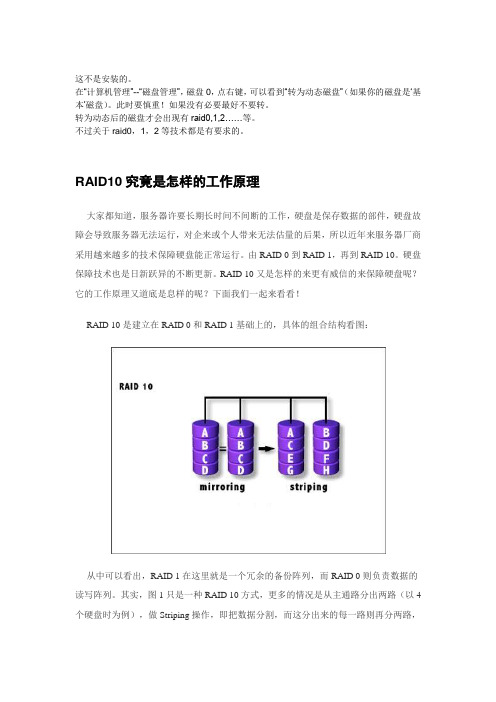
RAID 10又是怎样的来更有威信的来保障硬盘呢?它的工作原理又道底是息样的呢?下面我们一起来看看!RAID 10是建立在RAID 0和RAID 1基础上的,具体的组合结构看图:从中可以看出,RAID 1在这里就是一个冗余的备份阵列,而RAID 0则负责数据的读写阵列。
其实,图1只是一种RAID 10方式,更多的情况是从主通路分出两路(以4个硬盘时为例),做Striping操作,即把数据分割,而这分出来的每一路则再分两路,做Mirroring操作,即互做镜像。
这就是RAID 10名字的来历(也因此被很多人称为RAID 0+1),而不是像RAID 5、3那样的全新等级。
由于利用了RAID 0极高的读写效率和RAID 1较高的数据保护、恢复能力,使RAID 10成为了一种性价比较高的等级,目前几乎所有的RAID控制卡都支持这一等级。
但是,RAID 10对存储容量的利用率和RAID 1一样低,只有50%。
下面就让我们总结一下它的特点:RAID 10介绍—RAID 10的写和恢复操作模式二、RAID 10的写和恢复操作模式1、认识RAID 10Raid 10是一个Raid 0与Raid1的组合体,它是利用奇偶校验实现条带集镜像,所以它继承了Raid0的快速和Raid1的安全。
RAID 1介绍与制作
一、软制作镜像卷(系统层面的RAID
1): 只有Windows 2000、XP Professional、Server 2003支持镜像卷的; 1、装有至少2块硬盘,将基本磁盘升级为动态磁盘, 例将磁盘1的简单卷x和磁盘2的未指派空间组合成一 个镜像卷; 2、右击洗盘1的简单卷x,选择添加镜像; 3、在“添加镜像”对话框中选择磁盘2,单击“添 加镜像”按钮; 系统就会磁盘2的未指派空间创建一个与磁盘x相同 的卷,并将磁盘1的x卷的内容复制到2的镜像卷中, 卷颜色变为红色;(中断和删除其步骤基本相同)
有操作系统的制作RAID
打开BIOS中 的控制芯片 启动操作系统安装 HighPoint 370驱动
1:
关机将 源盘和 镜像盘 接在 IDE3、 4口
重启系统 完成创建
进入HighPoint 370 BIOS设置 RAID 1(步骤 见上文介绍)
RAID 1使用:
RAID 1提供最高的数据 安全保障。同样,由于 数据的百分之百备份, 备份数据占了总存储空 间的一半,因而Mirror 的磁盘空间利用率低, 存储成本高。Mirror虽 不能提高存储性能,但 由于其具有的高数据安 全性,使其尤其适用于 存放重要数据,如服务 器和数据库存储等领
RAID的分类
RAID技术分为几种不同的等级,分别可以提供不同 的速度,安全性和性价比。根据实际情况选择适当 的RAID级别可以满足用户对存储系统可用性、性能 NRAID 和容量的要求。
RAID分类:
JBOD RAID0
RAID
RAID1 RAID0+1 RAID3 RAID5 、、、、 、、
5、RAID模式选择完成会自动退出到上一级 菜单进行“Disk Drives(磁盘驱动器)”选 择,一般来说直接回车就行了。 (1)、下 一项设置是条带单位大小,缺省值为64kB, 没有特殊要求可以不予理睬。 (2)、接着 是“Start Create(开始创建)”的选项,在 你按下“Y”之前,请认真想想是否还有重要 的数据留在硬盘上,这是你最后的机会!一 旦开始创建RAID,硬盘上的所有数据都会被 清除。(3)、创建完成以后BIOS会提示进 行镜像的制作 ,过程有点漫长;
HighPoint 数据RAID配置和FnL监控软件安装指南(Windows)说明书
SRD7101P/SRD7101PB /SRD7204P /SRD7104P/ SRD7104PB/SRD7140P/SRD7140PB /CRD7104PB /CRD7101PB Driver & FnL Monitor Software Installation Guide (Windows)Version v1.00Copyright © 2021 HighPoint Technologies, Inc.All rights reservedContentsOverview (1)Prerequisites for a Data-RAID Configuration (2)Installing the Device Driver (3)1.Verify that Windows recognizes the controller (3)2.Download the Device Driver (3)3.Install the Device Driver (4)Updating the Device Driver (6)1.Check the Driver version (6)2.Download the Device Driver (7)3.Shutdown and Remove the Device (7)4.Uninstall the old Device Driver (7)5.Install the new Device Driver (9)Uninstalling the Device Driver (11)Installing the FnL Management Software (FnL Monitor & CLI) (12)Uninstalling the FnL Management Software (13)Troubleshooting (15)The FnL Monitor will not start after double-clicking the desktop icon. (15)BSOD (Blue Screen of Death) (16)How to Turn off Quick Shutdown for Windows (16)Controller and Drive Detection Issues (18)Appendix (19)How to Collect Debug View Logs (19)How to Collect INF Logs (20)How to Collect System Logs (21)Collecting Windows Dump Files (22)OverviewThis guide includes important hardware/software requirements, installation & upgrade procedures, and troubleshooting tips for using SRD7101P/SRD7101PB/SRD7204P/SRD7104P/SRD7104PB/SRD7140P/ SRD7140PB/CRD7104PB/CRD7101PB NVMe AIC RAID Drives with a Windows operating system. PrerequisitesThis section describes the base hardware and software requirements for the SRD7101P/SRD7101PB/ SRD7204P/SRD7104P/SRD7104PB/SRD7140P/SRD7140PB/CRD7104PB/CRD7101PB PCIe 3.0 NVMe AIC RAID Drives.Driver InstallationThis section covers driver installation, driver upgrade and driver uninstallation procedures for SRD7101P/ SRD7101PB/SRD7204P/SRD7104P/SRD7104PB/SRD7140P/SRD7140PB/CRD7104PB/CRD7101PB NVMe AIC RAID Drives.Management Software InstallationThis section explains how to download and install the SRD7101P/SRD7101PB/SRD7204P/SRD7104P/ SRD7104PB/SRD7140P/SRD7140PB/CRD7104PB/CRD7101PB FnL Monitor Management Software S uite for Windows operating systems. The download includes both the Web RAID Management Interface (FnL Monitor), and the CLI (Command Line Interface).TroubleshootingPlease consult this section if you encounter any difficulties installing or using the SRD7101P/ SRD7204P SRD7101PB/ SRD7104P/SRD7104PB/SRD7140P/SRD7140PB/CRD7104PB/CRD7101PBNVMe AIC RAID Drives. It includes descriptions and solutions for commonly reported technical issues.AppendixA selection of useful information and web links for the SRD7101P/SRD7101PB/SRD7204P/SRD7104P/ SRD7104PB/SRD7140P/SRD7140PB/CRD7104PB/CRD7101PB NVMe AIC RAID Drives.Prerequisites for a Data-RAID ConfigurationThe SRD7101P/SRD7101PB/SRD7204P/SRD7104P/SRD7104PB/SRD7140P/SRD7140PB/CRD7104PB/CRD7101PB NVMe AIC RAID Drives can support Data-RAID arrays. In order to usera Data-RAID array, you will need the following:1. A PCIe 3.0 slot with x8 or x16 lanes. The SRD7104P/SRD7104PB/SRD7101P/SRD7101PB/SRD7140P/SRD7140PB/CRD7104PB/CRD7101PB must be installed into a PCIe 3.0 slot with x16 dedicated lanes, The SRD7204P can be installed into a PCIe 3.0 x8 or x16 slot.2.Make sure any non-HighPoint drivers are uninstalled for any SSD’s hosted by the FnLseries RAID controllers. 3rd party software and manufacturer provided drivers may prevent the FnL from functioning properly.Warnings:1)Failing to remove the AIC Drive and SSD’s when uninstalling the driver may result in dataloss.2)Always make sure the FnL driver is installed before moving a FnL series NVMe AIC RAIDDrives & RAID array to another Windows system.Windows operating systems will always load the default NVMe support after the FnL driver has been uninstalled, or if it detects the present of a card when no driver has been loaded – this driver will only recognize the NVMe SSD’s as separate disks.If the SSD’s are recognized separately, any data they contain may be lost – this includes RAIDconfiguration data.Installing the Device DriverThe following section discusses driver installation for a non-bootable NVMe configuration.1.Verify that Windows recognizes the controllerAfter installing the FnL controller into the motherboard, power on the computer, boot the Windows operating system, and open Device Manager.A.Expand the Disk drives tab. Each NVMe SSD’s installed into the SRD7101P/SRD7101PB/SRD7204P/SRD7104P/SRD7104PB/SRD7140P/SRD7140PB/ CRD7104PB/CRD7101PBcontroller should be displayed here.B.Expand the Storage Controllers tab. You should see a “Standard NVM Express Controller”entry for each NVMe SSD that is installed into the AIC RAID Drive.Example screenshot SRD7104:AB2.Download the Device DriverDownload the appropriate FnL driver from the NVMe AIC RAID Drives Software Downloads webpage.SRD7101P/SRD7101PB:https:///srd7101p-overviewSRD7104P/SRD7104PB:https:///srd7104p-overviewSRD7204P:https:///srd7204p-overviewSRD7140P/SRD7140PB:https:///srd7140p-overviewCRD7101PB:https:///crd7101pb-overviewCRD7104PB:https:///crd7104pb-overview3.Install the Device DriverA.Locate the driver download and open the file.B.Double-click setup.Note: If installation does not start, you may have to manually start setup using AdministratorPrivileges. Right-click setup, select Run as Administrator from the menu, and confirm the pop-up window to proceed.After driver installation is complete, click OK to reboot.C.Once Windows has rebooted, open Device Manager to check the status of the driver.Expand Storage controllers and click on the HighPoint NVMe RAID Controller entry. View the properties and click the Driver tab:Example screenshot (SRD7104)Note: The driver revision shown in the screenshots may not correspond with current software releases. Please make sure to download the latest driver updates from the product’s Software Updates page.D.First, make sure the FnL Monitor has been installed (see FnL Monitor install). Open the FnLMonitor and make sure the SSD.’s / arrays are properly recognized.Note: Please refer to Appendix A to verify that your Device Manager entries correspond with the driver version you have installed.Updating the Device DriverNote: Before attempting to update the driver entry, ensure that the AIC RAID Drive is removed from the motherboard.1.Check the Driver versionOpen Device Manager to check the current driver version. Expand Storage controllers and click on the HighPoint NVMe RAID Controller entry. View the properties and click the Driver tab:Example screenshot (SRD7104)2.Download the Device DriverDownload the latest driver from the controller’s Software Downloads webpage.SRD7101P/SRD7101PB:https:///srd7101p-overviewSRD7104P/SRD7104PB:https:///srd7104p-overviewSRD7204P:https:///srd7204p-overviewSRD7140P/SRD7140PB:https:///srd7140p-overviewCRD7101PB:https:///crd7101pb-overviewCRD7104PB:https:///crd7104pb-overview3.Shutdown and Remove the DeviceA.Power down the system and remove the NVMe AIC RAID Drives from the motherboard.Note: Failing to remove the FnL controller from the motherboard during the uninstall process may result in data loss.Whenever the driver is uninstalled, Windows will attempt to install the default NVMe support,which may corrupt the RAID configurations and any data stored on SSD’s hosted by the FnLcontroller.B.Power on the system and boot Windows.4.Uninstall the old Device DriverA.Access Control Panel and select Programs→ Programs and Features, and click on the HighPointNVMe Driver entry.B.Click Uninstall/ChangeIf the HPT controller is not removed from the motherboard during the uninstall process, Windows will notify you that RAID data may be destroyed.C.After uninstalling the driver, click OK to reboot.D.After Windows has rebooted, access Control Panel to make sure the driver has been uninstalled.If there are no HighPoint NVMe RAID Driver entries present, the driver has been successfully uninstalled:5.Install the new Device DriverA.Locate the driver download and open the file.B.Double-click setup.Note: If the update does not start, you may have to manually start setup using AdministratorPrivileges. Right-click setup, select Run as Administrator from the menu, and confirm the pop-up window to proceed.C.Windows will notify you that the driver is already installed. Click OK to reboot.D.After entering the system, shut down the system.In the shutdown state, connect the FnLcontroller to the motherboard.E.Boot into the system.F.Once Windows has rebooted, open Device Manager to check the status of the driver. ExpandStorage controllers and click on the HighPoint NVMe RAID Controller entry. View theproperties and click the Driver tab:Note: The driver revision shown in the screenshots may not correspond with current software releases. Please make sure to download the latest driver updates from the product’s Software Updates page.G.First, make sure the FnL Monitor has been installed (see FnL Monitor install). Open the FnLMonitor and make sure the SSD.’s / arrays are properly recognized.For Example: SRD7204Uninstalling the Device Driver1.Power down the system and remove the NVMe AIC RAID Drives from the motherboard.Note: Failing to remove the FnL controller from the motherboard during the uninstall process may result in data loss. Whenever the driver is uninstalled, Windows will attempt to install the default NVMe support, which may corrupt the RAID configurations and any data stored on SSD’s hosted by the FnL controller.2.Power on the system and boot Windows.3.Access Control Panel and select Programs→ Programs and Features, and click on the HighPointNVMe Driver entry.4.Click Uninstall/Change5.After uninstalling the driver, click OK to reboot.6.After Windows has rebooted, access Control Panel to make sure the driver has been uninstalled. Ifthere are no HighPoint NVMe RAID Driver entries present, the driver has been successfullyuninstalledInstalling the FnL Management Software (FnL Monitor & CLI)The HighPoint FnL Management Software (FnL Monitor and CLI utilities) are used to monitor NVMe SSD’s hosted by the NVMe AIC RAID Drives. Download the latest software package from the HighPoint website:SRD7101P/SRD7101PB:https:///srd7101p-overviewSRD7104P/SRD7104PB:https:///srd7104p-overviewSRD7204P:https:///srd7204p-overviewSRD7140P/SRD7140PB:https:///srd7140p-overviewCRD7101PB:https:///crd7101pb-overviewCRD7104PB:https:///crd7104pb-overview1.Extract the package and double-click the FnL Monitor program to install the software.2.Once installed, locate the Management icon on the desktop and double-click to start the FnL Monitorinterface.Uninstalling the FnL Management Software1.Access Control Panel and select Programs→ Programs and Features, and click on the FnL Monitorentry.2.Click Uninstall/Change3.After uninstalling the driver, click Finish.TroubleshootingNote: When troubleshooting your NVMe AIC RAID Drives, make sure all of the Prerequisites have been met before proceeding.The FnL Monitor will not start after double-clicking the desktop icon.1.This is often the result of a missing driver or improperly installed driver. Open Device Managerand check under Storage Controllers.If the Driver is properly installed, you should see a HighPoint NVMe Controller entry forNVMe AIC RAID Drives, followed by HighPoint NVMe RAID Controller entry:Example screenshot (SRD7104)Note: The driver revision shown in the screenshots may not correspond with current software releases.Please make sure to download the latest driver updates from the product’s Software Updates page.2.You should also check to make sure hptsvr is running under Task Management → Services. Ifthe status of hptsvr process is Stopped, right-click on this entry and select Start from the menu:BSOD (Blue Screen of Death)There are three scenarios in which a BSOD may occur with AIC RAID DriveWindows displays a BSOD when the AIC RAID Drive is installed.If you are running Windows 10, please make sure that any Quick Shutdown options are disabled – these features can cause a BSOD when the AIC RAID Drive is installed into or removed from your motherboard. BSODs can be avoided by completely powering off your system.How to Turn off Quick Shutdown for Windowse administrator privileges to access the Command Prompt utility:b.Enter the following command and press Enter:powercfg / h offc.To make sure the setting has been disabled, enter the following command and pressEnter:powercfg / ad.Shut down the computer and remove the AIC RAID Drive from the motherboard;e.Restart the system and open the SRD7101P/SRD7101PB/SRD7204P/SRD7104P/SRD7104PB/SRD7140P/SRD7140PB/CRD7104PB/CRD7101PB driver download.f.Double-click Setup to reinstall the driver; if you are prompted to uninstall the driver, youwill need to follow the prompts and restart. After rebooting, double-click Setup once more to install the driver.After the driver installation is complete, shut down the computer. The AIC RAID Drive insert into the motherboard PCIe slot.g.Power on the system, boot Windows and access the FnL Monitor; if the FnL Monitorcan't connect, you need to restart again.h.If it fails to start the second time, please access our Online Support portal and submit asupport ticket.Note:If you are running a Server version of windows, and encounter a BSOD at bootup,please collect the following information: Windows version & build numbers, MemoryDump and System event Log1. A BSOD is encountered when installing the driver:If you experience a BSOD during driver installation, please collect the following information:Memory Dump, INF log, Debug Log, System Event log, and submit a new support ticket via our Online Support Portal.2.If Windows reports that driver installation has failed:a.Please collect these debugging information: INF log, Debug Log, DeviceManager/Storage Controller screen shot, System Event logNote:If you experience a BSOD or error when installing the driver, please ensure that any Quick Shutdown options are not enabled– Quick shutdown can cause a BSOD when removing theAIC RAID Drive from your motherboard, and plugging it back in. BSODs can be avoided bycompletely powering off your system:Controller and Drive Detection Issues•If your motherboard or Windows is unable to detect the NVMe AIC RAID Drives or NVMe SS D’s, please shutdown the system and try moving the NVMe AIC RAID Drives to another PCIeslot.•Make sure any unrelated NVMe devices are removed from the motherboard while troubleshooting the SRD7101P/SRD7101PB/SRD7204P/SRD7104P/SRD7104PB/SRD7140P/SRD7140PB/CRD7104PB/CRD7101PB NVMe AIC RAID Drives.AppendixHow to Collect Debug View LogsIf other troubleshooting steps fail to solve the problem, we suspect that the driver and management softwa re cannot establish a connection with the SRD7101P/SRD7101PB/SRD7204P/SRD7104P/SRD7104PB/ SRD7140P/SRD7140PB/CRD7104PB/CRD7101PB NVMe AIC RAID Drives. We will provide you with a Debug version of the driver to collect information about the problem you areexperiencing.To install the Debug driver, follow the standard driver installation procedure (please refer to theSRD7101P/SRD7101PB/SRD7204P/SRD7104P/SRD7104PB/SRD7140P/SRD7140PB/CRD7104PB/ CRD7101PB NVMe AIC RAID Drives User Guide). After installing the driver, follow the steps below:1.Download the DebugView utility from https:///files/DebugView.zip.2.Unzip, right-click on the icon, and run DebugView with administrator privileges. Select CaptureWin32, Capture Kernel, Enable Verbose Kernel Output, and Pass in the Capture toolbar.3.If the utility displays an “access denied” message, rename the following file:C:\Windows\System32\drivers\Dbgv.sys For example, rename it to “Dbgv.sys1”, i.e change the file type.4.Save the information printed by DebugView and send this to our support department.5.If required, we will provide management software information collection tools for the NVMeRAID Manager interface.How to Collect INF Logs1.Go to drive C→ Windows→ INF, and locate the setuppapi.dev and setupapi.setup logs:INF logs can be used to check what kind of software has been installed into the Windowssystems.2.Please access Device Manager, Storage Controllers, and check the properties for the HighPointentry. Click on Driver Details and take a screenshot – include this with the log files you submit for your support case.How to Collect System LogsIn addition to DebugView logs, System Logs can aid our Support department diagnose and resolve the support issues you have submitted. The System Log typically records errors, device failures, and software or driver related incidents. This information can help our engineers narrow down or even identify the source of the problem you are experiencing.System Log1.Click the Windows button towards the bottom left-hand corner of your desktop, and click on theSearch field.2.Type Event Viewer and click the icon as shown below:3.Expand the Windows Log folder and select System:4.Select Save All Events as… and save the .evtx file in an easy to find location.Collecting Windows Dump FilesWindows Dump files are snap shots that show which processes were running at the time of the event or failure. If possible, locate and upload the following files to your support case:•Memory.dmp•Minidump.dmpTo locate the dump files, check the C:\Windows directory and search for Memory.dmp andMinidump.dmp:。
HighPoint RocketRAID 1740 SATA Raid卡部件规格书说明书

HighPoint Technologies, Inc. (Confidential)HighPoint RocketRAID HighPoint RocketRAID 17401740 SA SATA TA TA Raid 卡部件规格书卡部件规格书REV REV::1.0(以下简称“本规格书”)目 录录一、本规格书适用产品及型号产品型号: HighPoint RocketRAID 1740二、 技术规格产品描述 处理器无SATA 控制器 Marvell 6042板载内存 无 扩展内存 无PCI PCI 32bit@33/66 MHz接口 3.3/5V 通道类型 SATA150通道数量 4自动修复 支持RAID 级别 0,1,5,10,JBOD条带大小设置 支持 控制器cache 控制 不支持 硬盘cache 控制不支持 SAF-TE 支持初始化模式 可选:1、不用初始化,2、正常初始化。
Online Array Expansion支持Online Array Roaming支持 Online Volume Migration 支持 热备功能 支持 电池 无 报警功能有HighPoint Technologies, Inc. (Confidential) 指示灯 有 跳线 无 板卡基材材料 0230物理尺寸 159mm ×64mm挡片 高挡板120mm*18mm/low 挡板80mm*18.4mmPCB 版本 V1.1 管理软件 有(英文界面)工作环境Windows ,Linux ,Unix ,Mac ,RedFlag板卡的其他未描述到的部分见本卡说明书操作三、软件版本四、兼容操作系统具体兼容情况请参照该部件测试报告和兼容列表操作系统Windows 2000 Server 西文版Windows 2000 Server 中文版Windows 2000 Advanced Server 西文版 Windows 2000 Advanced Server 中文版 Windows XP 西文版 Windows XP 中文版 Windows2003 西文版 Windows2003 中文版 Windows Vista Windows 2008Red Hat Enterprise Linux 3.0,3.1,4.0,4.1,4.2,4.3,4.4,5.0 SuSE Linux 8.1 ~ 10.2 Redflag 4.1 adserver FreeBSD 4.3 ~ 6.2MacOS X 10.3.x on Apple PowerMac G4/G5/PRO systems软件 版本号 BIOS V2.0DriverMS-Windows V2.0SuSE linuxV2.2 RedHat linux V2.2FreeBSDV1.02HighPoint Technologies, Inc. (Confidential)五、 IQC 检验指导部件名称SATA RAID 卡 物料编码 MADUHA04序号项 目 项 目 描 述 1 产品型号:HighPoint RocketRAID1740 SATA Raid 卡PCB 号或其他特征标识1 尺寸,认证,PCB 版本87.8mm×64.3mm,REV:V1.1,94V-0,UL2 处理器3 SAS 控制器 Marvell 64454 内存 无5 扩展内存 无6 PCI PCI-E 4X7 接口 3.3/5V8 通道类型 SAS9 通道数量 4 10 FW(Flash) 支持2附件驱动光盘,数据线4根,手册1本,短档片1个六、样品视图RR1740 RAID 卡外观图卡外观图。
RAID的几种特性

在企业中,针对数据存储,我们往往关注两个方面,一是数据的安全性,二是数据的读写速度,然而现实中,这两个方面在相同的投资情况下是相互冲突的,要达到比较高的安全性,往往需要牺牲读写速度为代价,如何选择合适的存储方式,在实际业务中至关重要;具体以下几种场景:1、数据分散写入,磁盘空间最大化利用,读写速度快,数据能接收丢失的风险:使用RAID0,针对数据拆分会用,提高数据的读写速度,没有数据冗余,磁盘损坏,数据一定会丢失2、磁盘安全最大化,每份数据同时写入两块磁盘,读写速度相对比较慢,数据不会拆分写入:使用RAID1 ,每份数据都分别存储在两块磁盘,最好的情况下可以做到损坏一半的磁盘下,数据不丢失。
3、磁盘利用率及读取速度为RAID0,RAID1比较折中,每次读写至少要进行四次IO,RIAD5 适应用大文件的读写,比如视频等,即可充分利用磁盘数据又有相对的冗余,在一块磁盘损坏的情况下,可以不丢失数据。
4、数据安全性高,磁盘利用率为50%,数据读写时会进行拆分,RAID10,适合离散数据,如数据库等写入次数比较多,数据量比较少的系统。
引用文章一、一.RAID定义RAID(Redundant Array of Independent Disk 独立冗余磁盘阵列)技术是加州大学伯克利分校1987年提出,最初是为了组合小的廉价磁盘来代替大的昂贵磁盘,同时希望磁盘失效时不会使对数据的访问受损失而开发出一定水平的数据保护技术。
RAID就是一种由多块廉价磁盘构成的冗余阵列,在操作系统下是作为一个独立的大型存储设备出现。
RAID可以充分发挥出多块硬盘的优势,可以提升硬盘速度,增大容量,提供容错功能够确保数据安全性,易于管理的优点,在任何一块硬盘出现问题的情况下都可以继续工作,不会受到损坏硬盘的影响。
二、RAID的几种工作模式(仅讨论RAID0,RAID1,RAID5,RAID10这四种,这四种比较典型)1、RAID0 (又称为Stripe或Striping--分条)即Data Stripping数据分条技术。
高点6Gb s SAS SATA RAID HBA用户指南说明书
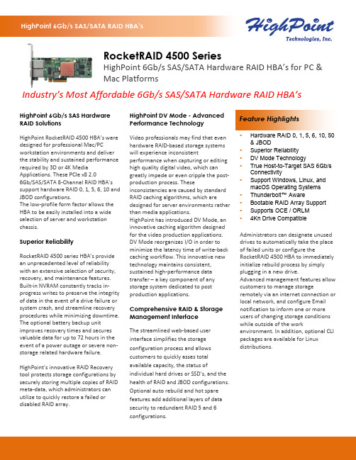
Administrators can designate unused drives to automatically take the place of failed units or configure the RocketRAID 4500 HBA to immediately initialize rebuild process by simply plugging in a new drive. Advanced management features allow customers to manage storageremotely via an internet connection or local network, and configure Email notification to inform one or more users of changing storage conditions while outside of the work environment. In addition, optional CLI packages are available for Linux distributions.Feature Highlights HighPoint 6Gb/s SAS Hardware RAID Solutions HighPoint RocketRAID 4500HBA’s were designed for professional Mac/PCworkstation environments and deliver the stability and sustained performancerequired by 3D or 4K Media Applications. These PCIe x8 2.0 6Gb/SAS/SATA 8-Channel RAID HBA’s support hardware RAID 0, 1, 5, 6, 10 and JBOD configurations. The low-profile form factor allows the HBA to be easily installed into a wide selection of server and workstation chassis. Superior Reliability RocketRAID 4500 series HBA’s provide an unprecedented level of reliability with an extensive selection of security, recovery, and maintenance features. Built-in NVRAM constantly tracks in-progress writes to preserve the integrity of data in the event of a drive failure or system crash, and streamline recovery procedures while minimizing downtime. The optional battery backup unit improves recovery times and secures valuable data for up to 72 hours in the event of a power outage or severe non-storage related hardware failure.HighPoint’s innovative RAID Recovery tool protects storage configurations bysecurely storing multiple copies of RAID meta-data, which administrators can utilize to quickly restore a failed or disabled RAID array.HighPoint DV Mode - Advanced Performance Technology Video professionals may find that even hardware RAID-based storage systems will experience inconsistent performance when capturing or editing high quality digital video, which can greatly impede or even cripple the post-production process. Theseinconsistencies are caused by standard RAID caching algorithms, which aredesigned for server environments rather than media applications.HighPoint has introduced DV Mode, aninnovative caching algorithm designedfor the video production applications. DV Mode reorganizes I/O in order to minimize the latency time of write-back caching workflow. This innovative new technology maintains consistent, sustained high-performance data transfer – a key component of any storage system dedicated to post production applications. Comprehensive RAID & Storage Management Interface The streamlined web-based user interface simplifies the storage configuration process and allowscustomers to quickly asses totalavailable capacity, the status of individual hard drives or SSD’s, and the health of RAID and JBOD configurations. Optional auto rebuild and hot sparefeatures add additional layers of datasecurity to redundant RAID 5 and 6configurations.• Hardware RAID 0, 1, 5, 6, 10, 50 & JBOD • Superior Reliability • DV Mode Technology • True Host-to-Target SAS 6Gb/s Connectivity • Support Windows, Linux, and macOS Operating Systems • Thunderbolt™ Aware • Bootable RAID Array Support • Supports OCE / ORLM • 4Kn Drive Compatible RocketRAID 4500 SeriesHighPoint 6Gb/s SAS/SATA Hardware RAID HBA’s for PC & Mac Platforms Industry’s Most Affordable 6Gb/s SAS/SATA Hardware RAID HBA’sHPTBBU-05Backup Units grant additional layers of data protection in the case of critical system faults andhardware failures.EXT-MS-1MMS (for RocketRAID 4522SGL)supports a data bandwidth up to 4x 6Gb/s between the RocketRAID 4522SGL RAID controllerinstalled in the host system, and the drive enclosure via SFF-8088 ports. Each cable can connectup to 4x Hard Drives or SSDs.INT-MS-1M4SC (for RocketRAID 4520SGL) -(SFF-8087) to 4x SATA device cable designed for use with HighPoint RocketRAID SAS/SATAcontrollers, and has been tested with a wide range of Enterprise and Pro-NAS class SAS/SATAhard drives and SSD's up to 16TB in capacity.RocketStor 6414SRocketRAID 4522 to house up to 4x 2.5" or 3.5" Hard Drives or SSDs. Two RocketStor 6414S canbe used with each RocketRAID 4522SGL HBA.RocketStor 6418SRocketRAID 4522SGL to house up to 8x 2.5" or 3.5" Hard Drives or SSDs.Phone 1-408-942-5800 Phone + 86(10)-53519056 (Ext. 8003)Fax 1-408-942-5801 Fax + 86-10-6897-5074E-mail ************************E-mail ************************Website Website Address 41650 Christy St. Fremont Address ROOM 512, Building 1,CA, 94538 No 4 JinHang Xi Rd, ShunYi DistrictBeijing, 101318, China。
阵列卡设置不再忧 各种阵列卡设置教程

阵列卡设置不再忧各种阵列卡设置教程阵列卡设置不再忧各种阵列卡设置教程2010-06-01 09:40以下是各种阵列卡的设置教程,让您在进行阵列卡设置时不再忧愁。
1、磁盘阵列简介:磁盘阵列(Disk Array)是由一个硬盘控制器来控制多个硬盘的相互连接,使多个硬盘的读写同步,减少错误,增加效率和可靠度的技术。
RAID是Redundant Array of Inexpensive Disk的缩写,即"独立磁盘冗余阵列"(最初为"廉价磁盘冗余阵列")的缩略语,1987年由Patterson,Gibson 和Katz在加州大学伯克利分院的一篇文章中定义。
RAID阵列技术允许将一系列磁盘分组,以实现提高可用性的目的,并提供为实现数据保护而必需的数据冗余,有时还有改善性能的作用。
RAID技术是一种工业标准,各厂商对RAID 级别的定义也不尽相同。
目前对RAID级别的定义可以获得业界广泛认同的有4种,RAID 0、RAID 1、RAID 0+1和RAID 5,我们常见的主板自带的阵列芯片或阵列卡能支持的模式有:RAID 0、RAID 1、RAID 0+1。
RAID 0是无数据冗余的存储空间条带化,它将所有硬盘构成一个磁盘阵列,可以同时对多个硬盘做读写动作,但是不具备备份及容错能力,具有成本低、读写性能极高、存储空间利用率高等特点,在理论上可以提高磁盘子系统的性能。
RAID 1是两块硬盘数据完全镜像,可以提高磁盘子系统的安全性,技术简单,管理方便,读写性能均好。
但它无法扩展(单块硬盘容量),数据空间浪费大,严格意义上说,不应称之为"阵列"。
RAID 0+1综合了RAID 0和RAID 1的特点,独立磁盘配置成RAID 0,两套完整的RAID 0互相镜像。
它的读写性能出色,安全性高,但构建阵列的成本投入大,数据空间利用率低,不能称之为经济高效的方案。
常见的阵列芯片有三种:Promise(乔鼎信息)、HighPoint、AMI(美商安迈)。
磁盘阵列卡操作说明
磁盘阵列操作说明
图
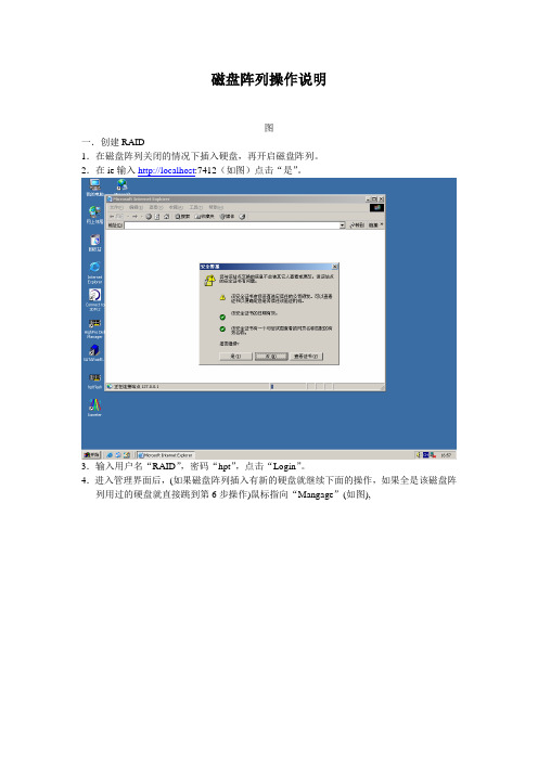
一.创建RAID
1.在磁盘阵列关闭的情况下插入硬盘,再开启磁盘阵列。
2.在ie输入http://localhost:7412(如图)点击“是”。
3.输入用户名“RAID”,密码“hpt”,点击“Login”。
4.进入管理界面后,(如果磁盘阵列插入有新的硬盘就继续下面的操作,如果全是该磁盘阵列用过的硬盘就直接跳到第6步操作)鼠标指向“Mangage”(如图),
点击“Device”→(如图),
点击“Initialize Devices”(如图)选中所有磁盘,
5.(如图)鼠标指向“Manage”点击“Array”。
6.(如图)点击“Create Array”,
选择RAID级别“RAID5”(如图),
(如图)选择初始化类型“Background”,
(如图)选中所有磁盘,点击“Create”→“确定”。
5.初始化完成之后,进入“计算机管理”点击“磁盘管理”(如图),
点击“取消”,创建RAID逻辑盘(如图)。
二.删除RAID
进入管理软件“Highpoint Web RAID Managemnet”,(如图),
点击“Mantenance”→(如图)点击“stop”→
“Mantenance”(如图)
点击“DELETE”弹出对话框。
点击“确定”RAID删除完成。
作站、服务器、磁盘阵列
工作站、服务器、磁盘阵列第一,工作站的定义:工作站是一种高档的微型计算机,通常配有高分辨率的大屏幕显示器及容量很大的内存储器和外部存储器,并且具有较强的信息处理功能和高性能的图形、图像处理功能以及联网功能。
工作站根据软、硬件平台的不同,一般分为基于RISC(精简指令系统)架构的UNIX系统工作站和基于Windows、Intel的PC工作站。
UNIX工作站是一种高性能的专业工作站,具有强大的处理器(以前多采用RISC芯片)和优化的内存、I/O(输入/输出)、图形子系统,使用专有的处理器(Alpha、MIPS、Power等)、内存以及图形等硬件系统,专有的UNIX操作系统,针对特定硬件平台的应用软件,彼此互不兼容。
PC工作站则是基于高性能的X86处理器之上,使用稳定的Windows NT及Windows2000、WINDOWS XP等操作系统,采用符合专业图形标准(OpenGL)的图形系统,再加上高性能的存储、I/O(输入/输出)、网络等子系统,来满足专业软件运行的要求;以NT、WIN2000、XP为架构的工作站采用的是标准、开放的系统平台,能最大程度的降低拥有成本。
另外,根据体积和便携性,工作站还可分为台式工作站和移动工作站。
台式工作站类似于普通台式电脑,体积较大,没有便携性可言,但性能强劲,适合专业用户使用。
移动工作站其实就是一台高性能的笔记本电脑。
但其硬件配置和整体性能又比普通笔记本电脑高一个档次个人的计算机和大学里的电子阅览室都算工作站.第二,服务器的定义:服务器是计算机的一种,它是网络上一种为客户端计算机提供各种服务的高性能的计算机,它在网络操作系统的控制下,将与其相连的硬盘、磁带、打印机、Modem及昂贵的专用通讯设备提供给网络上的客户站点共享,也能为网络用户提供集中计算、信息发表及数据管理等服务。
从上面的介绍可以看出,服务器首先是一种计算机,只不过是能提供各种共享服务――如硬盘空间、数据库、文件、打印等――的高性能计算机。
芯片组raid卡报错解决方案

芯片组raid卡报错解决方案篇一:Intel主板RAID1恢复方法及图解测试以EP-5LDA+ GLI为例,先使用2个Seagate 80G SATAII硬盘组好RAID1.安装驱动时除了主板芯片组,声卡,网卡,显卡驱动之外,还必须加载“IntelApplication Accelerator Raid edition full Version”驱动,Intel主板主要通过此驱动来完成RAID镜像恢复. 以下为RAID损坏和恢复的全过程,请参考:1.首先拔掉其中的一个硬盘,开机第二画面显示为一个不完整的RAID1,进入系统.点击开始菜单-Intel(R)Matrix Storage manager-Intel (R)Matrix Storage Console,查看硬驱和RAID状态项提示“一个硬驱丢失,RAID卷性能下降”表明RAID1已被损坏。
2.加入一个SAMSUNG 80G SATAII空磁盘,进入系统打开Intel (R)Matrix Storage Console对话框,点击“恢复RAID1数据保护”前的图标。
3.然后再点击“现在就重建RAID卷”。
4.查看硬驱和RAID状态提示“一个RAID卷正在重建”。
5.重建过程需要一段时间,等到提示“所有的硬驱和RAID卷均正常”,表示RAID1已恢复。
篇二:阵列卡正确安装调试方法阵列卡正确安装调试方法!!首先我们把创世纪系统第一个区克隆到C盘,这里的C 盘是指你事先找一个普通的IDE硬盘连接在主板上,这个盘可以以后做系统和备份盘,也可以用来把系统克隆上阵列,这个在后面提到。
克隆好以后,关机。
我们把TX2卡插到*近AGP槽的第2或者第4各pci上面,之所以这样,是为了尽可能避免与网卡,尤其是千兆卡冲突,创世纪官方推荐网卡插在第1或者第3、5槽,就是单数槽。
据说是避免与软声卡之类的冲突;插好以后,千万不要连接硬盘,否则可能根本不能用。
插好卡以后我们进入20XX系统,系统会提示发现新硬件,提示安装驱动,选择下一步以后,提示输入驱动的位置,我们PROMISE提供的安装软磁盘,在确定驱动位置的地址兰输入A:\WIN20XX,选择下一步,直到安装完成,然后重新启动,还是不要连接硬盘,在进入20XX,看到设备管理器的磁盘驱动器下面出现PROMISE DEVICE。
HighPoint NVMe macOS Installation Guide
HighPoint NVMemacOSInstallation GuideVersion 1.9.0Copyright © 2020 HighPoint Technologies, Inc.All rights reserved.Last updated on Jan, 2020Contents1.Overview (1)2.Installing the package (1)Driver installation steps on macOS(10.14/10.15) (1)3.Uninstalling the package (4)Driver uninstallation steps on macOS (10.14/10.15) (4)4.Troubleshooting (5)Troubleshooting driver installation (5)Troubleshooting driver uninstallation (7)1.OverviewThis document describes how to install the HighPoint NVMe RAID Controller Driver ona macOS system. It is assumed that you have physically installed the controller into oneof your Mac system’s free PCIe slots.The software download contains one installation package, HighPointNVMe.pkg, which contains the NVMe device driver.Important: Before installing the software, you should log onto the system as a System Administrator.2.Installing the packageDriver installation steps for macOS (10.14/10.15)Current drivers can be downloaded from each product’s Software Downloads webpage.After downloading the appropriate driver, open the driver package by double-clicking the icon, and follow the procedure outlined below:1)Locate the download and double click the package to start the installer. Click theContinue button:2)macOS will prompt you to install the driver. Click Install to proceed.3)You will be prompted that a reboot is needed to install the software. Click ContinueInstallation.4)If no pop-ups appear, please proceed to the next step of installation. Click Restart.5)If you receive a popup window prompting you for permission, click Open SecurityPreferences.i.Make sure App Store and identified developers is checked, and then clickAllow.ii.You will receive a popup window, prompting you to restart. Click OK.iii.Return to the driver installation window. Click Restart to restart the system.6)After the system restarts, the driver’s status can be viewed under SystemInformation; The figure below shows that the driver has been loaded normally.3.Uninstalling the packageDriver uninstallation steps for macOS (10.14/10.15)1)To uninstall the NVMe driver, you will need to open a Terminal window and enterthe following command:sudo rm -rf /Library/Extensions/HighPointNVMe.kext4.TroubleshootingTroubleshooting driver installationThe product does not work after installing the driver, and the WEBGUI page displays the following warning message:To resolve this issue:1)Make sure the latest version of macOS has been installed. If an update isrequired, update macOS as promoted. Once complete, reinstall the driver: Repeatthe steps outlined in section 2.2)If your Mac has a T2 chip, select “No Security” under the “StartupSecurity Utility” options.i.Determining if your Mac has a T2 chip: If it says Apple T2 Securitychip in the righthand column, continue on to the Disabling Secure Bootsection bellow;ii.Disabling Secure Boot: Restart the computer and then press the Command + R keys simultaneously. Keep holding the keys down until theApple logo appears.iii.When the menu bar says: macOS Utilities, you are booted into Recovery mode. Launch the Startup Security Utility application by selecting it fromthe Utilities menu.iv.When the Startup Security Utility window appears, select No Security under the Secure Boot options.v. A dialog box will appear, telling you that you will need to authenticate as an Administrator to make changes, click the Enter macOS Password...button.vi.Select Restart from the Apple menu to restart your Mac, and wait for your normal Desktop to appear.3)If the product is still not working after updating to the latest official version ofmacOS, please contact our Customer Support Department.Web Support: /websupport/ Troubleshooting driver uninstallationThe product still works after uninstalling the driver, and the WEBGUI can be used normally.Please open a Terminal window and use the following command to uninstall thedriver:sudo rm -rf /Library/Extensions/HighPointNVMe.kextsudo kextcache –i /If the driver still works after executing the above command, please contact our Customer Support Department.Web Support: /websupport/。
热插拔 SATA RAID 设置 说明书

图 4-44
Set Boot Mark:设置启动的硬盘或阵列。 选中该项回车后,会出现和 RAID 卡相连的硬盘和阵列列表,移动光标选到相应的硬盘 或阵列,回车选中,则出现“BOOT”标记,则系统从该硬盘(阵列)上启动,如图 4 -45。
图 4-45
Remove Boot Mark:取消启动阵列。将光标移动到原启动盘(阵列),回车,取消系统 从此硬盘(阵列)的启动。 Device Mode 改变硬盘或阵列的设置。把光标移动到相应的硬盘或阵列上,回车,显示 出该盘或阵列支持的模式,如图 4-46,选择相应模式,回车确认。
阵列的名字,按回车确认,返回阵列配置界面,如图 4-29。
图 4-29
3. 在阵列配置界面中,用方向键移动光标选中 Select Devices ,回车,出现硬盘选择窗口, 如图 4-30。
图 4-30
把光标移动到需要创建阵列的硬盘上,用回车键选中,当所需硬盘选完后,按 ESC 退出 硬盘选择窗口,回到阵列配置窗口。 4. 当配置 RAID0、10、5 时,需要选择条带大小。用方向键移动光标选中 Block Size 回车, 在弹出的列表中选择所需大小的条带(单位为 K),回车确认,如图 4-31。
当阵列中一块硬盘故障时,需要使用该项加入新硬盘,重建阵列。选中需要替换硬盘的 阵列,点击“Operation”菜单,选择“Add Disk”。如图 4-68。
raid控制器是什么?我的电脑有未知硬件raid控制器怎样使用?

RAID控制器是什么?我的电脑有未知硬件RAID控制器,怎样使用?RAID全称为“Redundant Array of Inexpensive Disks”,中文意思是“独立冗余磁盘阵列”(简称磁盘阵列)。
简单地说,RAID是一种把多块独立的硬盘(物理硬盘)按不同方式组合起来形成一个硬盘组(逻辑硬盘),从而提供比单个硬盘更高的存储性能和提供数据冗余的技术。
所谓数据冗余是指数据一旦发生损坏,利用冗余信息可以使受损数据得以恢复,从而保障了数据的安全性。
RAID最初用于高端服务器市场,不过随着计算机应用的快速发展,RAID技术已经渗透到很多领域。
如今,在家用电脑主板中,RAID控制芯片也随处可见。
就目前而言,PATA、SATA以及SCSI接口的硬盘都可以通过相应的RAID控制芯片来组建RAID系统。
在家用电脑上,我们一般只用到RAID 0、RAID 1这两种磁盘阵列方式。
一、什么是RAID 0RAID 0使用一种称为“条带”(Striping)的技术把数据分布到各个磁盘上。
在那里每个“条带”被分散到连续“块”(Block)上,数据被分成从512字节(Byte)到数兆字节的若干块后,再交替写到磁盘中。
第1块数据被写到磁盘1中,第2块数据被写到磁盘2中,依此类推。
当系统到达阵列中的最后一个磁盘时,就写到磁盘1的下一分段,如此进行下去直到数据写完为止。
RAID 0方式的优点是采用数据分块、并行传送方式,能够大幅度提高数据读写速度,理论上数据写入速度可以达到单块硬盘速度的双倍,而数据读取的时间则是单块硬盘所用的一半。
但是,RAID 0没有数据保护能力。
如果一个磁盘出现故障,那么数据就会全部丢失。
RAID 0非常适合于视频、图像的制作和编辑处理工作。
二、什么是RAID 1RAID 1也被称为镜像,它把磁盘阵列中的硬盘分成相同的两组,互为镜像。
也就是说,数据在写入一个磁盘上的同时,也被完全复制到另一个磁盘上。
因此,如果一个磁盘的数据发生错误,或者硬盘出现了坏道,那么另一个硬盘上的备份数据可以挽回损失。
HighPoint RAID 驱动程序安装指南说明书

在Microsoft Windows10上安装HighPoint RAID驱动程序快速安装指南修订版:1.0HighPoint Technologies,Inc.版权版权所有©2012HighPoint Technologies,Inc.本文件包含受国际版权法保护的材料。
保留所有权利。
未经HighPoint Technologies公司明确书面许可,不得以任何形式出于任何目的复制、传播或转录本手册的任何部分。
商标本手册中提及的公司和产品仅供识别之用。
本手册中出现的产品名称或品牌名称可能是也可能不是其各自所有者的注册商标或版权。
在使用HighPoint产品之前备份您的重要数据,使用风险自负。
在任何情况下,HighPoint均不对因HighPoint产品或手册中的任何缺陷或错误导致的任何利润损失或直接、间接、特殊、偶然或后果性损害负责。
本手册中的信息如有更改,恕不另行通知,并不代表HighPoint的承诺。
通知已尽力确保本手册中的信息准确无误。
HighPoint不对本文中包含的技术错误、排印错误或其他错误承担任何责任。
目录在安装驱动程序之前,请考虑以下事项 (4)执行以下步骤以安装Windows8驱动程序 (4)感谢 (8)客户支持 (9)在安装驱动程序之前,请考虑以下事项:▪如果您想使用RocketRAID来进行主存储,则需要确保可引导的分区小于2TB。
你需要把Windows10驱动程序放在USB、CD光盘或DVD光盘上。
▪I果您想使用RocketRAID作为辅助存储器,请从HighPoint网站下载最新的驱动程序,并遵循以下步骤。
请执行以下步骤以安装Windows8驱动程序。
1.启动Windows10操作系统。
右键单击Windows徽标,然后从弹出式菜单中选择“设备管理器”。
图1:设备管理器2.从设备管理器中找到RAID控制器。
右键单击RAID控制器设备,并从弹出窗口中选择“更新驱动程序软件”。
HighPoint具有磁盘阵列功能的无盘网络系统解决方案

HighPoint具有磁盘阵列功能的无盘网络系统解决方案一、方案背景在计算机网络飞速发展的今天,已形成“谁拥有网络,谁就拥有未来”的局面。
而对于随着迅速发展应运而生的“网络”来说,网民对其的要求越来越高。
而对于网络的建设者来说,如何将网络的构建、性能、运行状况和维护等方面运作好,也是越来越棘手的问题。
网络给用户带来了很多方便,同时也带来了不少的烦恼。
首先,人们对网络的依赖已经延伸到更广阔的使用空间,各种基于网络环境开发出来的软硬应用也日渐成为主流。
随着基于网络的远程教育、在线多媒体视听和多种互联网应用软件的开发,人们已经不再满足于简单的网海畅游和浏览查询,他们要通过网络与远在千里之外的朋友互相交流,要在网上享受远程教育的互动……如前不久开展的“网络卡拉OK 大赛”,网民们在网络上唱的如火如荼、开心不已。
而网络,又一次充分展现了其强大的功能和丰富多彩性。
如此多样化高标准的需求也对网络的运行、系统配置和整体构架提出了更高的要求。
其次,对于网络经营者来说,每天上网的顾客来来往往,网上病毒的传输又难以操控,总会给网络带来一些不安全因素,还有上网顾客因不正确操作更易引起系统崩溃等事件的发生。
在传统的网络建设中,即使主机对客户机实施实时监控,也难免客户机中一些顾客的非法操作,甚至在不知不觉中通过光驱,优盘等更先进的技术手段带入病毒。
再次,在传统的网络建设模式中,除了网络建设必备的网络服务器(或配置较高的主机)、网络拓扑结构、包括集线器,交换机等在内的网络设备外,还有一项投入就是直接面对网民的网络终端(或称客户机)。
一个中、大规模的网络,其终端一般在40-100台左右,因此网络的初期投入成本将占有相当大的一部分。
如何缩减这一部分的成本,同时又保持客户机良好的性能,即成为建设中的一个非常重要的问题。
综上所述,传统的网络建设模式已经不能适应网络发展的需求。
为了在激烈的竞争中立足,保证良好的系统(本地,网络)运行速度和稳定性,并承受长时间连续运作的能力。
- 1、下载文档前请自行甄别文档内容的完整性,平台不提供额外的编辑、内容补充、找答案等附加服务。
- 2、"仅部分预览"的文档,不可在线预览部分如存在完整性等问题,可反馈申请退款(可完整预览的文档不适用该条件!)。
- 3、如文档侵犯您的权益,请联系客服反馈,我们会尽快为您处理(人工客服工作时间:9:00-18:30)。
HighPoint RAID Controller Programming Guide(v1.0)Date Version Description2012/10/10 V1.0 Initial versionCopyright © 2012 HighPoint Technologies, Inc.All rights reserved.Table of contentsPart I Function Description (4)1.hpt_get_version (4)2.hpt_get_controller_count (5)3.hpt_get_controller_info (6)4.hpt_get_channel_info (7)5.hpt_get_logical_devices (8)6.hpt_get_device_info (9)7.hpt_create_array (10)8.hpt_delete_array (11)9.hpt_get_driver_capabilities (12)10.hpt_device_io (13)11.hpt_set_array_state (14)12.hpt_get_event (15)13.hpt_rebuild_data_block (16)14.hpt_verify_data_block (17)15.hpt_add_spare_disk (18)16.hpt_remove_spare_disk (19)17.hpt_set_array_info (20)18.hpt_set_device_info (21)19.hpt_add_disk_to_array (22)20.hpt_rescan_devices (23)21.hpt_ide_pass_through (24)22.hpt_query_remove (25)23.hpt_remove_devices (26)24.hpt_create_transform (27)25.hpt_set_vdev_info (28)26.hpt_calc_max_array_capacity (29)27.hpt_init_disks (30)28.hpt_i2c_transaction (31)29.hpt_scsi_passthrough (32)30.hpt_load_bios (33)31.hpt_load_flash (34)32.hpt_get_driver_parameter (35)33.hpt_get_parameter (36)34.hpt_set_driver_parameter (37)35.hpt_get_physical_devices (38)36.hpt_get_enclosure_count (39)37.hpt_get_enclosure_info (40)38.hpt_get_enclosure_element_info (41)Part ⅡData Structure Description (42)1.Constants (42)2.CONTROLLER_INFO (46)3.CHANNEL_INFO (49)4.LOGICAL_DEVICE_INFO (50)5.DEVICE_INFO (52)6.IdendifyData (55)7.HPT_ARRAY_INFO (57)8.CREATE_ARRAY_PARAMS (60)9.DRIVER_CAPABILITIES (62)10.DRIVER_CAPABILITIES_V2 (64)11.HPT_EVENT (65)12.TIME_RECORD (66)13.ALTERABLE_ARRAY_INFO (67)14.ALTERABLE_DEVICE_INFO (68)15.IDE_PASS_THROUGH_HEADER (69)16.HPT_SCSI_PASSTHROUGH_IN (70)17.HPT_SCSI_PASSTHROUGH_OUT (71)18.HPT_DRIVER_PARAMETER (72)19.ENCLOSURE_INFO (73)20.SES_ELEMENT_STATUS (75)Part I Function Description1.hpt_get_versionThe hpt_get_version function returns the version number of our programming interface.DWORD hpt_get_version();ParametersThis function does not have any parameters.Return valuesThis function returns the version number of programming interface. If it fails, it returns -1. RemarksThis function should be called before all other functions. If it fails, please do not call other functions.2.hpt_get_controller_countThe hpt_get_controller_count function returns the number of HPT HBA in your system. int hpt_get_controller_count();ParametersThis function does not have any parameters.Return valuesThis function returns the number of controllers. If it fails, it returns -1.3.hpt_get_controller_infohpt_get_controller_info_v2hpt_get_controller_info_v3The hpt_get_controller_info_vx series of function return the specified controller's information. Higher version function is compatible with the lower version.int hpt_get_controller_info(int id,PCONTROLLER_INFO pInfo);int hpt_get_controller_info_v2(int id,PCONTROLLER_INFO_V2 pInfo);int hpt_get_controller_info_v3(int id,PCONTROLLER_INFO_V3 pInfo);ParametersidThe index of the controller where 0 means the first one.pInfo[out] Pointer to CONTROLLER_INFO(_VX) structure that receives the information. Return valuesIf success, this function returns 0, otherwise returns -1.4.hpt_get_channel_infohpt_get_channel_info_v2The hpt_get_channel_info_vx series of function return the specified channel's information. Higher version function is compatible with the lower version.int hpt_get_channel_info(int id,int bus,PCHANNEL_INFO pInfo);int hpt_get_channel_info_v2(int id,int bus,PCHANNEL_INFO_V2 pInfo);ParametersidThe index of the controller where 0 means the first one.busThe index of the channel of the controller where 0 means the first one.pInfo[out] Pointer to CHANNEL_INFO(_VX)structure that receives the information. Return valuesIf success, this function returns 0, otherwise returns -1.5.hpt_get_logical_devicesThe hpt_get_logical_devices function returns all the logical devices in the system controlled by driver. int hpt_get_logical_devices(DEVICEID * pIds,int nMaxCount);ParameterspIds[out] Pointer to a DEVICEID array. You should allocate the memory for pIds.nMaxCountSpecifies the max capacity of pIds. The two parameters should match each other.Return valuesIf success, Number of logical device is returned and all logical devices' ids are put into pIds, otherwise returns -1.6.hpt_get_device_infohpt_get_device_info_v2hpt_get_device_info_v3hpt_get_device_info_v4The hpt_get_device_info_vx series of function return the specified device's information.Higher version function is compatible with the lower version.int hpt_get_device_info(DEVICEID id,PLOGICAL_DEVICE_INFO pInfo);int hpt_get_device_info_v2(DEVICEID id,PLOGICAL_DEVICE_INFO_V2 pInfo);int hpt_get_device_info_v3(DEVICEID id,PLOGICAL_DEVICE_INFO_V3 pInfo);int hpt_get_device_info_v4(DEVICEID id,PLOGICAL_DEVICE_INFO_V4 pInfo);ParametersidThe logical device's ID.pInfo[out] Pointer to LOGICAL_DEVICE_INFO(_VX) structure that receives the information. Return valuesIf success, this function returns 0 and all the device information is put into pInfo, otherwise returns -1.7.hpt_create_arrayhpt_create_array_v2hpt_create_array_v3The hpt_create_array_vx series of function creates an array according to your setting and returns its device ID.Higher version function is not compatible with the lower version, please call compatible according to driver version.DEVICEID hpt_create_array(PCREATE_ARRAY_PARAMS pParam);DEVICEID hpt_create_array_v2(PCREATE_ARRAY_PARAMS_V2 pParam);DEVICEID hpt_create_array_v3(PCREATE_ARRAY_PARAMS_V3 pParam);ParameterspParamPointer to CREATE_ARRAY_PARAMS(_VX) structure that specifies the array properties. Return valuesIf success, this function returns the array's device ID, otherwise returns 0.8.hpt_delete_arrayThe hpt_delete_array function deletes the specified array. int hpt_delete_array(DEVICEID id,HPT_U32 options);ParametersidSpecifies which array you want to delete.optionsReserved.Return valuesIf success, this function returns 0, otherwise returns -1.9.hpt_get_driver_capabilitieshpt_get_driver_capabilities_v2The hpt_get_driver_capabilities_vx series of function returns the specified driver's feature information.int hpt_get_driver_capabilities(PDRIVER_CAPABILITIES cap);int hpt_get_driver_capabilities_v2(PDRIVER_CAPABILITIES_V2 cap);ParameterscapPointer to a DRIVER_CAPABILITIES(_VX) structure.The caller better set dwSize member to sizeof (DRIVER_CAPABILITIES_VX).Return valuesIf success, this function returns 0 and all the driver information is put into cap, otherwise returns -1.10.hpt_device_iohpt_device_io_v2The hpt_device_io_vx series of function is obsolete and should not be used.int hpt_device_io(DEVICEID id,int cmd,HPT_U32 lba,HPT_U32 nSector,void * buffer);int hpt_device_io_v2(DEVICEID id,int cmd,LBA64 lba,HPT_U32 nSector,PVOID buffer);ParametersidDevice ID you want to read or write data.cmdIf you want to read or write. It can be IO_COMMAND_READ or IO_COMMAND_WRITE.lbaSpecifies the LBA address you want to read or write.nSectorSpecifies how many sectors of data you want to read or write.bufferPointer to the your data buffer you want to write to device or receive data.Return valuesIf success, this function returns 0, otherwise returns -1.11.hpt_set_array_stateThe hpt_set_array_state function starts or aborts a VERIFY, REBUILD, INITIALIZE, or TRANSFORM operation to a relevant kind of RAID.Before you perform an operation to an array please check its flags to see if it support the operation. int hpt_set_array_state(DEVICEID idArray,HPT_U32 state);ParametersidArraySpecifies which array you want to set state.stateIt can be AS_REBUILD_START, AS_REBUILD_ABORT, AS_INITIALIZE_START, AS_INITIALIZE_ABORT, AS_VERIFY_START, AS_VERIFY_ABORT,AS_TRANSFORM_START, AS_TRANSFORM_ABORT.Return valuesIf success, this function returns 0, otherwise returns -1.RemarksIf you want to start duplication of a RAID 1 or RAID 0/1 array, set state toAS_REBUILD_START. If you want to abort the duplication, set state toAS_REBUILD_ABORT. When you start or abort the duplication, the driver will save current LBA address duplicated in the disk, so when you next time reboot, you can see the array's flag contains ARRAY_FLAG_NEEDBUILDING. If you do not want this flag appears, you can set state to AS_REBUILD_COMPLETE to enforce the driver to write the max value to the disks.You can use hpt_get_device_info function to get the rebuilding progress percentage value.12.hpt_get_eventThe hpt_get_event function returns the latest event occurred.int hpt_get_event(PHPT_EVENT pEvent);ParameterspInfo[out] Pointer to HPT_EVENT structure that receives the information. Return valuesIf success, this function returns 0, otherwise returns -1.13.hpt_rebuild_data_blockhpt_rebuild_data_block_v2The hpt_rebuild_data_block_vx series of function rebuild the specified sectors of a redundant array. int hpt_rebuild_data_block(DEVICEID idArray,HPT_U32 Lba,HPT_U8 nSector);int hpt_rebuild_data_block_v2(DEVICEID idArray,HPT_U64 Lba,HPT_U16 nSector);ParametersidArraySpecifies which array you want to rebuild.LbaSpecifies the start address.nSectorSpecifies number of sectors you want to duplicate.Return valuesIf success, this function returns 0, otherwise returns -1.RemarksThis function is obsolete. Use hpt_set_array_state to rebuild an array.14.hpt_verify_data_blockhpt_verify_data_block_v2The hpt_verify_data_block_vx series of function verify the specified sectors of a redundant array. int hpt_verify_data_block(DEVICEID idArray,HPT_U32 Lba,HPT_U8 nSector);int hpt_verify_data_block_v2(DEVICEID idArray,HPT_U64 Lba,HPT_U16 nSector);ParametersidArraySpecifies which array you want to verify.LbaSpecifies the start address.nSectorSpecifies number of sectors you want to duplicate.Return valuesIf success, this function returns 0, otherwise returns -1.RemarksThis function is obsolete. Use hpt_set_array_state to verify an array.15.hpt_add_spare_diskThe hpt_add_spare_disk function adds a physical device into spare pool. int hpt_add_spare_disk(DEVICEID idDisk);ParametersidDiskSpecifies which device you want to add to spare pool.Return valuesIf success, this function returns 0, otherwise returns -1.16.hpt_remove_spare_diskThe hpt_remove_spare_disk function removes a spare disk from spare pool. int hpt_remove_spare_disk(DEVICEID idDisk);ParametersidDiskSpecifies which device you want to remove from spare pool.Return valuesIf success, this function returns 0, otherwise returns -1.17.hpt_set_array_infoThe hpt_set_array_info function changes an array's name or description.int hpt_set_array_info(DEVICEID idArray,PALTERABLE_ARRAY_INFO pInfo);ParametersidArraySpecifies which array you want to re-configure.pInfoPointer to structure ALTERABLE_ARRAY_INFO that contains which field(s) will be changed. Return valuesIf success, this function returns 0, otherwise returns -1.18.hpt_set_device_infohpt_set_device_info_v2The hpt_set_device_info_vx function changes a device's transferring mode.int hpt_set_device_info(DEVICEID idDisk,PALTERABLE_DEVICE_INFO pInfo);int hpt_set_device_info_v2(DEVICEID idDisk,PALTERABLE_DEVICE_INFO_V2 pInfo);ParametersidDiskSpecifies which device you want to re-configure.pInfoPointer to structure ALTERABLE_DEVICE_INFO(_VX) that contains which field(s) will be changed.Return valuesIf success, this function returns 0, otherwise returns -1.RemarksIf idDisk==0, call this function to stop buzzer on the adapterNow, the provided DLL and interface does not support changing transferring mode of a device.19.hpt_add_disk_to_arrayThe hpt_add_disk_to_array function adds a disk to a broken array to re-construct that array.int hpt_add_disk_to_array(DEVICEID idArray,DEVICEID idDisk);ParametersidArrayThe array you want to add disk to.idDiskThe device you want to add to array.Return valuesIf success, this function returns 0, otherwise returns -1.RemarksWhen a RAID 1, RAID 5,RAID 3, etc. array's flag contains ARRAY_FLAG_BROKEN, you can add a physical hard disk to the array to get a normal array. After you add the disk to the array, the array maybe needs rebuilding; the provided DLL will perform this operation automatically. You should check the array's working flag to see if it contains ARRAY_FLAG_REBUILDING. If it is being rebuilt, you may get its progress by calling hpt_get_device_info.20.hpt_rescan_devicesThe hpt_rescan_devices function lets the driver to check all disks attached to HPT HBA.int hpt_rescan_devices();ParametersThis function has no parameters.Return valuesIf success, this function returns 0, otherwise returns -1.RemarksWhen system is running, if a disk is removed and at that time there are I/O operations on that disk, the driver will find the disk removed. But if no I/O, users removes a disk, the driver will notdetect it. In this case you should call this function to let driver to detect it.After this functions returns successfully, you should call hpt_get_event to see if there is a disk removed or plugged.21.hpt_ide_pass_throughhpt_ide_pass_through_v2The hpt_ide_pass_through_vx series of function sends a pass-through command directly to driver.int hpt_ide_pass_through(PIDE_PASS_THROUGH_HEADER p);int hpt_ide_pass_through_v2(PIDE_PASS_THROUGH_HEADER_V2 p);ParametersPSpecifies a pointer to a caller supplied pass-through command buffer. The buffer is used for both input and output. The output buffer begins right after the input buffer. The buffer size should be sizeof (IDE_PASS_THROUGH_HEADER_VX)*2 plus any input or output data size.Return valuesIf the call is successful, this function returns 0, and the output buffer will hold the register values and any data returned by the device. If the call fails, the function returns -1.RemarksThis function can only work with drivers with pass-through support.22.hpt_query_removeThe hpt_query_remove function checks if specified devices can be removed from system. int hpt_query_remove(HPT_U32 ndev,DEVICEID *pIds);ParametersndevSpecifies the number of devices.pIdsSpecifies a pointer to an array of device IDs.Return valuesIf success, this function returns 0, otherwise returns -1.23.hpt_remove_devicesThe hpt_query_remove function removes (unregister) specified devices from system. int hpt_remove_devices(HPT_U32 ndev,DEVICEID *pIds);ParametersndevSpecifies the number of devices.pIdsSpecifies a pointer to an array of device IDs.Return valuesIf success, this function returns 0, otherwise returns -1.24.hpt_create_transformhpt_create_transform_v2The hpt_create_transform_vx series of function creates an OCE/ORLM instance. int hpt_create_transform(DEVICEID idArray,PCREATE_ARRAY_PARAMS_V2 destInfo);int hpt_create_transform_v2(DEVICEID idArray,PCREATE_ARRAY_PARAMS_V3 destInfo);ParametersidArraySpecifies the source array to be transformed.destInfoSpecifies the destination array that will be transformed to.Return valuesIf success, this function returns 0, otherwise returns -1.25.hpt_set_vdev_infoThe hpt_set_vdev_info function sets logical or physical device parameters. int hpt_set_vdev_info(DEVICEID id,PSET_VDEV_INFO pInfo);ParametersidSpecifies the device ID.pInfoSpecifies the new parameters to be set.Return valuesIf success, this function returns 0, otherwise returns -1.26.hpt_calc_max_array_capacityhpt_calc_max_array_capacity_v2The hpt_calc_max_array_capacity_vx series of function calculates the maximum possible capacity for an array.int hpt_calc_max_array_capacity(DEVICEID source,PCREATE_ARRAY_PARAMS_V2 destInfo,HPT_U64 * cap);int hpt_calc_max_array_capacity_v2(DEVICEID source,PCREATE_ARRAY_PARAMS_V3 destInfo,HPT_U64 * cap);ParameterssourceSpecifies a source device ID when calculating OCE/ORLM destination capacity. For a normal array, it should be zero.destInfoSpecifies the array information, based on which the capacity will be calculated.capSpecifies a pointer to the output value.Return valuesIf success, this function returns 0, otherwise returns -1.27.hpt_init_disksThe hpt_init_disks function initializes a set of disks.int hpt_init_disks(HPT_U32 ndev,DEVICEID *pIds);ParametersndevSpecifies the number of devices.pIdsSpecifies a pointer to an array of device IDs.Return valuesIf success, this function returns 0, otherwise returns -1.RemarksDisk initialization is not required on all RAID controllers. This function can only be used with controllers that require disk initialization.28.hpt_i2c_transactionThe hpt_i2c_transaction function performs a transaction on the I2C bus.int hpt_i2c_transaction(HPT_U8 *indata,HPT_U32 inlen,HPT_U8 *outdata,HPT_U32 outlen,HPT_U32 *poutlen);ParametersindataSpecifies a pointer to the input data buffer.I2C input buffer format: byte 0 is controller id, followed by any number of I2C command packets, with each packet in below format:for write: [data length], [addr with R/W bit], [...] (data bytes to be written)for read: [data length], [addr with R/W bit]the last command packet must be 2 bytes ([length], 0). this length, if not zero, will be used by the controller to receive data as an I2C slave.inlenSpecifies the input data buffer size.outdataSpecifies a pointer to the output data buffer.outlenSpecifies the output data buffer size.poutlenSpecifies a pointer to a integer value to receive the actual size of output data. This parameter can be omitted.Return valuesIf success, this function returns 0, otherwise returns -1.RemarksThis function can only work with controllers with I2C support.29.hpt_scsi_passthroughThe hpt_scsi_passthrough function sends a SCSI pass-through command to a device. int hpt_scsi_passthrough(PHPT_SCSI_PASSTHROUGH_IN in,HPT_U32 insize,PHPT_SCSI_PASSTHROUGH_OUT out,HPT_U32 outsize);ParametersinHPT_SCSI_PASSTHROUGH_IN header pointer.insizeSpecifies the input data buffer size.outHPT_SCSI_PASSTHROUGH_OUT header pointerOutsizeSpecifies the output data buffer size.Return valuesIf success, this function returns 0, otherwise returns -1.30.hpt_load_biosThe hpt_load_bios function updates BIOS of HPT HBA from the image file. int hpt_load_bios(HPT_U32 dwControllerID,char* pBiosFileName,bool forced,LP_LOAD_BIOS_CALLBACK pCallback);Parameters:dwControllerIDController ID whose BIOS will be updated.pBiosFileNameFull path to the BIOS image file.forceIf it is true the BIOS image file will be updated without ID checking.pCallbackA callback function used to report updating progress.Return valuesIf success, this function returns 0, otherwise returns -1.31.hpt_load_flashThe hpt_load_flash function updates firmware from the image file. int hpt_load_flash(HPT_U32 dwControllerID,char* pBiosFileName);ParametersdwControllerIDController ID whose firmware will be updated.pBiosFileNameFull path to the firmware image file.Return valuesIf success, this function returns 0, otherwise returns -1.32.hpt_get_driver_parameterThe hpt_get_driver_parameter function returns the queried parameter value of a HPT HBA, such as, whether the HBA supports Auto Rebuild, Continue Rebuilding on Error or Rebuild Priority.int hpt_get_driver_parameter(PHPT_DRIVER_PARAMETER pParam);ParameterspParamA pointer to HPT_DRIVER_PARAMETER.Return valuesIf success, this function returns 0, otherwise returns -1.33.hpt_get_parameterThe hpt_get_parameter function performs same task as hpt_get_driver parameter function except it returns the cached parameter value, which set by hpt_get_driver parameter.int hpt_get_parameter(PHPT_DRIVER_PARAMETER pParam);ParameterspParamA pointer to HPT_DRIVER_PARAMETER.Return valuesIf success, this function returns 0, otherwise returns -1.34.hpt_set_driver_parameterThe hpt_set_driver_parameter function sets the parameter value of a HPT HBA. int hpt_set_driver_parameter(PHPT_DRIVER_PARAMETER pParam);ParameterspParamA pointer to HPT_DRIVER_PARAMETERNote: The parameter "Rebuild Priority" is unsupported.Return valuesIf success, this function returns 0, otherwise returns -1.35.hpt_get_physical_devicesThe hpt_get_physical_devices function returns all physical devices connected to the HPT HBA. int hpt_get_physical_devices(DEVICEID * pIds,int nMaxCount);ParameterspIds[out] Pointer to a DEVICEID array which costs nMaxCount * sizeof(DEVICEID). The caller should allocate the memory for pIds.nMaxCountSpecifies the max count of IDs.Return valuesIf success, number of physical devices is returned and all physical devices' ids are put into pIds, otherwise returns -1.36.hpt_get_enclosure_countThe hpt_get_enclosure_count function returns the number of enclosures connected to the HPT HBA.int hpt_get_enclosure_count(int ctlr_id);Parametersctlr_idThe index of the controller (count from 0).Return valuesIf success, this function returns the count of enclosures, otherwise returns -1.37.hpt_get_enclosure_infohpt_get_enclosure_info_v2hpt_get_enclosure_info_v3hpt_get_enclosure_info_v4The hpt_get_enclosure_info_vx series of function return the information of the specified enclosure.int hpt_get_enclosure_info(int ctlr_id,int enc_id,PENCLOSURE_INFO pInfo);int hpt_get_enclosure_info_v2(int ctlr_id,int enc_id,PENCLOSURE_INFO_V2 pInfo);int hpt_get_enclosure_info_v3(int ctlr_id,int enc_id,PENCLOSURE_INFO_V3 pInfo);int hpt_get_enclosure_info_v4(int ctlr_id,int enc_id,PENCLOSURE_INFO_V4 pInfo);Parametersctlr_idThe index of the controller where 0 means the first one.enc_idThe index of the enclosure of the controller where 0 means the first one.pInfo[out] Pointer to ENCLOSURE_INFO structure that receives the information.Return valuesIf success, this function returns 0,enclosure info is put into (*pInfo ), otherwise returns -1.38.hpt_get_enclosure_element_infoThe hpt_get_enclosure_element_info function returns the information of the specified enclosure element.int hpt_get_enclosure_element_info(int ctlr_id,int enc_id,int ele_id,PSES_ELEMENT_STA TUS pInfo);Parametersctlr_idThe index of the controller (count from 0).enc_idThe index of the enclosure of the controller (count from 0).ele_idThe index of the element of the enclosure (count from 0).pInfopointer to SES_ELEMENT_STATUS bufferReturn valuesIf success, this function returns 0 and e nclosure element info is put into *pInfo, otherwise returns -1.Part Ⅱ Data Structure Description1.ConstantsThe following constants are used in our programming interface for users.HPT_INTERFACE_VERSION Version of the programming interface.You must first issue a hpt_get_version()call to check if it matches HPT_INTERFACE_VERSION. If not, you should not call any of other functions.Device TypesLDT_ARRAY The device is an arrayLDT_DEVICE The device is a physical disk or CD-ROM or TAPE. Array and Device TypesAT_UNKNOWN The array type is not defined.AT_RAID0It is a RAID 0 array.AT_RAID1It is a RAID 1 array.AT_RAID5It is a RAID 5 array.AT_RAID6It is a RAID 6 array.AT_JBOD It is a JBOD array.PDT_UNKNOWN The device type is not defined.PDT_HARDDISK It is a hard disk.PDT_CDROM It is a CD-ROMPDT_TAPE It is a tape.Array FlagsARRAY_FLAG_DISABLED The array is disabled and OS cannot use it.ARRAY_FLAG_NEEDBUILDING The source disk's/array's contents do not consist with the target disk's/array's contents. You should perform duplication on this RAID 1 or RAID 0/1 array.ARRAY_FLAG_REBUILDING The array is being duplicated.ARRAY_FLAG_BROKEN Some member(s) of a RAID 1 or RAID 0/1 array fails, but OS can use the array. You should add disk to it to re construct and duplicate it.ARRAY_FLAG_BOOTDISK The array's MBR (Master Boot Record) contains bootable operation system. You should not delete this type of array unless you exactly know the system does not start from this array.ARRAY_FLAG_BOOTMARK This flag is set in BIOS when you set BOOT mark to a disk or array.ARRAY_FLAG_NEED_AUTOREB UILD This flags means a spare disk has taken over, and the array needs duplication.ARRAY_FLAG_VERIFYING The array is verifying. ARRAY_FLAG_INITIALIZING The array is initializing.ARRAY_FLAG_TRANSFORMING The array is transforming in progress. ARRAY_FLAG_NEEDTRANSFORMThe array needs transforming. Device FlagsDEVICE_FLAG_DISABLED The device is removed or I/O error occurs on it. It can be access by OS and it cannot be used as spare disk and array member.DEVICE_FLAG_BOOTDISK The device's MBR(Master Boot Sector) contains bootable operation system. If you want to specify it as an array member, only can it be a source of a RAID 1 and when creating, you specify flag CAF_CREA TE_AND_DUPLICATEDEVICE_FLAG_BOOTMARK This flag is set in BIOS when you set BOOT mark to a disk or array.DEVICE_FLAG_SATA SA TA or SAS device.DEVICE_FLAG_ON_PM_PORT PM portDEVICE_FLAG_SAS SAS deviceDEVICE_FLAG_SSD SSD deviceDEVICE_FLAG_IN_ENCLOSURE Device is in enclosureDEVICE_FLAG_UNINITIALIZED Device is not initialized, can't be used to create array DEVICE_FLAG_LEGACY Single disk & mbr contains at least one partition.DEVICE_FLAG_IS_SPARE It is a spare disk.Array rebuild controlAS_REBUILD_START Set this flag in function hpt_set_array_state() to start rebuild. AS_REBUILD_ABORT Set this flag in function hpt_set_array_state() to abort rebuild. Array and Device Configurationfield masksAAIF_NAME Set this flag to rename an array.ADIF_TCQ TCQ(Tagged Command Queuing)ADIF_NCQ NCQ(Native Command Queuing)ADIF_WRITE_CACHE Write cacheADIF_READ_AHEAD Read aheadADIF_SPIN_UP_MODE Spin up modeArray Creation FlagsCAF_FOREGROUND_INITIALIZE The array created with CAF_FOREGROUND_INITIALIZE flag will be reported to system till initialization is completed.CAF_BACKGROUND_INITIALIZE The array created with CAF_BACKGROUND_INITIALIZE flag is reported to system immediately.Event TypesET_DEVICE_REMOVED Disk removed. ET_DEVICE_PLUGGED Disk plugged in. ET_DEVICE_ERROR Disk I/O error. ET_REBUILD_STARTED Rebuild started. ET_REBUILD_ABORTED Rebuild aborted. ET_REBUILD_FINISHED Rebuild finished.。