热泵控制器使用说明书(v2.0)
智科热泵控制面板使用说明
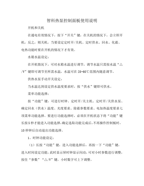
智科热泵控制面板使用说明开机和关机在通电有效情况下,按下“开关”键,在关机的情况下,会立即开机,反之,则关机。
当要设定定时开/关机、定时供水、回水、化霜、电热功能时要在开机的情况下才有效。
水箱水温设定:在开机情况下,可对水箱水温进行调节,调节水温只需按水温“△/V”键即可调节至所需水温,水温可在28-60℃范围内随意调节。
供热水泵手动开关设定:当水温达到设定供水温度要求时,按“供水”键即可供水。
菜单功能选择:按“功能”键,可进行时钟、定时开/关主机、定时开/关供水泵、确定回水(供水)温度、光度要求、除霜参数要求、电加热温度要求七项菜单功能选择。
要进行功能选择时,必须在开机状态下将“功能”键长按5秒才能进入功能选择,确定选取功能完成后,不再操作控制板时,10秒钟后自动退出功能选择。
1、时钟功能设定:(1)长按“功能”健,进入功能选择后,再按一下“功能”键,进入时间设定功能,此时显示屏时钟显示闪动,可对小时参数进行调整,按住“参数”“△/V”键,小时数字可上下调整。
(2)、完成小时设置后,再按“确认”键,进入分钟数设置,按住参数“A/V”键,分钟数可上下调整。
再按“确认”键,时钟设定完成。
2、主机定时设定:(1)、进入功能选择后,按二下“功能”键,显示屏“主机”菜单闪动,按“确认”键后进入主机定时功能。
(2)、时段选择或定时开关查询主机定时可选择3个时段,进入主机定时功能时,按“时段”键可对定时时段进行选择。
当时段定时完成后,可按“时段”键对定时时段进行查询。
某一项定时开、关有效时,显示屏定时开/关亮。
(3)、定时开设定按一下“定时”键,定时开闪动,同时时钟区闪动,按“参数”“A/V”键,可调整定时时间(设定精度为30分钟),再按“确认”键,定时开设定完成。
(4)按二下“定时”键,定时关闪动,设定方法与定时开一样。
(5)按三下“定时”键,取消定时设定。
当未退出定时功能时,连续按“定时”键,第一次按“定时”键设置定时开、第二次按“定时”键设置定时关、第三次按“定时”键,取消设置定时。
热泵控制器使用说明书(v2.0)
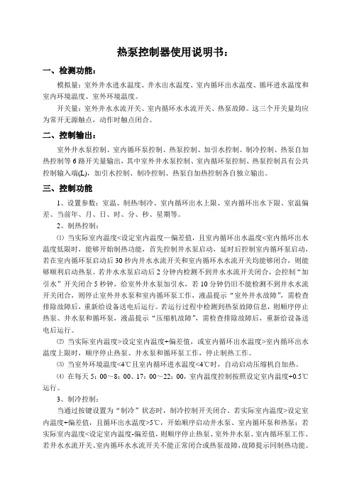
热泵控制器使用说明书:一、检测功能:模拟量:室外井水进水温度、井水出水温度、室内循环出水温度、循环进水温度和室内环境温度、室外环境温度。
开关量:室外井水水流开关、室内循环水水流开关、热泵故障。
这三个开关量均应为常开无源触点,动作时触点闭合。
二、控制输出:室外井水泵控制、室内循环泵控制、热泵控制、加引水控制、制冷控制、热泵自加热控制等6路开关量输出,其中室外井水泵控制、室内循环泵控制、热泵控制具有公共控制输入端(L),加引水控制、制冷控制、热泵自加热控制各自独立输出。
三、控制功能1、设置参数:室温、制热/制冷、室内循环出水上限、室内循环出水下限、室温偏差、当前年、月、日、时、分、秒、星期等。
2、制热控制:⑴当实际室内温度<设定室内温度—偏差值,且室内循环出水温度<室内循环出水温度低限时,能够开始制热功能,首先控制井水泵启动,延时后控制室内循环泵启动,若在室内循环泵启动后30秒内井水水流开关和室内循环水水流开关均能够闭合,则能够顺利启动热泵。
若井水水泵启动后2分钟内检测不到井水水流开关闭合,会控制“加引水”开关闭合5秒钟,给室外井水泵加引水,若10分钟仍旧不能检测不到井水水流开关闭合,则停止室外井水泵和室内循环泵工作,液晶提示“室外井水故障”,需检查排除故障后,重新给设备送电后运行。
若运行过程中检测到热泵故障信息,则顺序停止热泵、井水泵和循环泵,液晶提示“压缩机故障”,需检查排除故障后,重新给设备送电后运行。
⑵当实际室内温度>设定室内温度+偏差值,或室内循环出水温度>室内循环出水温度上限时,顺序停止热泵、井水泵和循环泵工作,停止制热工作。
⑶当室外环境温度<4℃且室内循环进水温度<4℃时,自动启动压缩机自加热。
⑷在每天5:00~8:00、17:00~22:00,室内温度控制按照设定室内温度+0.5℃运行。
3、制冷控制:当通过按键设置为“制冷”状态时,制冷控制开关闭合。
热泵专用恒温控制器(新)
热泵专用恒温控制器使用说明一、主要技术参数1、使用条件:◇运行电压:AC220V±20%,50Hz.◇运行环境温度:-15~+75℃◇储存温度:0~+80℃◇湿度要求:0~95%RH2、温度控制精度:±1℃二、使用说明※1、使用要求:热泵主机提供补冷水信号至恒温控制器作为电源供电,当主机无需补水时,热泵主控板不能提供电源给恒温器(即此状态下恒温器不能上电工作),否则会影响恒温器的正常工作。
建议使用我司的热泵电控板作为控制最为理想!2、控制器输出:输出水流开关信号至热泵主板水流开关检测端子,自来水停水时能自动停机。
3、控制器输入:热泵主机出水管温度传感器,检测出水温度。
4、控制器指示灯说明:黄色灯为补冷水指示灯,灯亮时表示热泵主机要求补水,供电给恒温器准备工作。
绿色灯亮时表示有足够的水流过,恒温器正常工作。
5、当自来水压力不够(水流量太小)时,应加水泵抽水。
25匹机型水流量每小时不小于4吨,13匹不小于2吨,5匹不小于1.5吨,3匹不小于1吨。
6、出水温度有三个温度值供选择: 55℃、50℃、45℃。
拔动恒温器外侧开关选择所需的出水温度(最上面55℃、中间50℃、最下面45℃)。
注:电脑芯片在上电时才检测开关状态,上电后再设置出水温度无效。
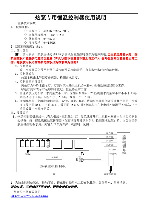
三、接线说明1、恒温控制器引出线一共有六根线(三组线)。
红、黑色线接热泵主机补水阀输出为恒温控制器的供电;白、棕色线接温度传感器(配有四分外螺纹铜头),检测出水温度;黄、绿色线接热泵主机控制板水流开关输入口作为保护、机控制。
见图一2、为防止接驳处氧化、接触不良,请在接口处用电工胶布包扎好,做好防水、防潮措施。
特别注意:三组线切不可接错,否则会损坏控制器。
四、安装说明(打※标记的是重点提示)※1、按恒温控制器标识的水流方向安装进、出水管。
2、为了安装牢固,可选择安装孔固定控制器。
图二3、严禁任何异物进入恒温控制器,在安装时特别注意不可让密封带进入控制器的管道里。
mini-ALFA-plus 热泵型冷水机组控制器 使用手册说明书
2.6 “SET”+“▼”键
按组合键“SET”+ “▼”键进入向参数程序模 块上载参数的功能。
·在常规工作模式下,按组合键“SET”+ “▼” 3 秒钟左右,参数装载的选 择菜单工作。
·符号 SN 01 显示,这表示列表 1 已被 选中。
可变参数。可变参数如下所示:
变量
代码
压缩机
C1
温度传感器 1(进水) St1
温度传感器 2(出水) St2
温度传感器 3 可选 St3
压力传感器 1 可选 SP1
除霜周期
CSbr
水泵
PCld
风机
Fan
报警记录
AL--:最近一次的报警
3. 当需要态(见下表)。
模式的改变只能在相关的显示信息关闭之才后 有效。
2.2.1 模式变换
如果 P13 的值为 1 或 2,仪表不能更改操作模 式(见详细说明)
2
只有当 P20=0 的时候,机组进入“待机”模 式。对应模式指示灯(制冷(夏季)或加热(冬 季))闪烁,面板显示“Stby”,报警时除外。 如果在“待机”状态下,设定 P20=1,仪表自 动退出此状态。 当开关在夏季/冬季模式之间切换时,机组停 止工作,并且四通阀反向;机组在延迟时间后 工作(在改变操作模式情况下,延迟时间由参 数 P45 设置,在除霜周期启动/停止情况下, 延时参数由 P35 设置),如果正在除霜周期启 动/停止期间(见第 10 章),则在除霜完成后, 机组继续工作。 在此情况下压缩机的最小工作时间不被考虑。 机组在“待机”状态下,防冻控制继续有效。 在除霜循环期间,是不允许进行模式变换的。
变频热泵系统用户手册说明书
HOME OWNER’S INFORMATIONSplit System,Variable SpeedHeat PumpA NOTE ABOUT SAFETYAny time you see thissymbol in manuals,instructionsand on the unit,be aware of the potential for personal injury. There are three levels of precaution:DANGER identifies the most serious hazards which will result in severe personal injury or death.WARNING signifies hazards that could result in personal injury or death.CAUTION is used to identify unsafe practices which would result in minor personal injury or product and property damage.NOTE is used to highlight suggestions which will result in enhanced installation,reliability,or operation.Our products are designed,tested and built in accordance with DOE standardized procedures;however,actual operating results and efficiencies may vary based on manufacturing and supplier tolerances,equipment configuration,operating conditions and installation practices.Identifying Your SystemYour new heat pump system is what we call a”split system.”It has an outdoor unit and an indoor unit connected to each other with copper tubing called refrigerant lines.Each of these units has a rating plate with the model and serial numbers you will need to reference when calling an authorized dealer about your system.Take a few moments now to locate those numbers and record them on the warranty included in this booklet.USING YOUR NEW SYSTEMYour heat pump system is controlled by a wall-mounted Observer®Wall Control or thermostat installed inside your home.See the Observer®Wall Control or thermostat Homeowner Guide for more details on system operation. VARIABLE SPEED OPERATIONYou may notice your system runs for longer periods of time. This system is designed to meet cooling or heating needs of the home at a wide range of conditions.Your indoor temperature will remain more consistent with fewer drafts, better humidity control,enhanced comfort and enhanced energy efficiency.HEATING AND COOLING YOUR HOMEFor heating or cooling operation,make sure the System or Mode control is set to the appropriate mode.Then,adjust the Temperature control to your desired setting.Finally,use the Fan control to select Automatic(turns on and off as heating is needed)or On(runs continuously).Depending on your typical heating needs,your home comfort system may also include a supplementary heating source that will automatically turn on as needed.You may also select this heat source manually if desired.OPERATION UNDER EXTREME CONDITIONS Your heat pump will run as long as necessary to maintain the indoor temperature selected on your Observer Wall Control or thermostat.On extremely hot days,your heat pump will run for longer periods at a time than on moderate days.Your system will also run for longer periods of time under the following conditions:S Frequent opening of exterior doorsS Operating laundry appliancesS Taking hot showersS More than the usual number of people present in the homeS More than the normal number of electric lights in useS Drapes or blinds are open on the sunny side of the home IMPORTANT HEAT PUMP FACTSHeat pump systems have a few unique features and operations that you should be aware of:S During the heating cycle,your heat pump delivers a constant flow of air at around95°to about105°F, compared to sudden blasts of hot air provided by a typical furnace.S Ice or frost may form on the outdoor coil during winter heating operation.Your heat pump will automatically melt the ice using its defrost cycle.During defrost,you may see steam or fog rising from the outdoor unit,which is normal.At the beginning and end of the defrost cycle,you may hear a”whoosh”sound coming from the unit.This is normal for heat pump applications.S Heat pumps installed in areas expecting snow are elevated with support feet.SOUNDYour new heat pump with SmartSense t technology is different from most heating and cooling systems.Because this is a variable speed system,it is designed to operate at different speeds depending on the temperature and humidity conditions.You may notice the sound coming from the outdoor unit changing from time to time,and from season to season.In winter,the system will operate at higher speeds as it gets colder outside to maintain its heating performance.The higher speed produces a higher sound.This change of speed allows the system to operate more efficiently and maintain comfortable conditions inside the home.You may also hear a slight hissing sound when near the outdoor unit in the off-cycle.This is the sound of system pressure equalization which is required to enable soft and easy starting of the next cycle.These sounds are normal and do not represent a problem with your system.ROUTINE MAINTENANCESimple,routine maintenance as described below will enhance your heat pump system’s ability to operate economically and dependably.Always remember the following safety precautions:S Keep Filter CleanA clogged or improperly installed air filter on your indoor unit will increase operating costs and shorten the life of the unit. For detailed filter cleaning information refer to indoor unit literature.4280250020110/11/2016Specifications subject to change without notice.switch.When drapes,furniture,toys or other common household items block vents,the restricted airflow lessens the system’s efficiency and life span.S Do Not Cover or Block Outdoor UnitThe outdoor unit needs unrestricted airflow.Do not cover it or place items on or next to it.Do not allow grass clippings, leaves,or other debris to accumulate on the sides or top of the unit.And,maintain a12”(304.8mm)minimum clearance between the outdoor unit and tall grass,vines,shrubs,etc.S Check Condensate DrainYour heat pump removes humidity from your home during the cooling season.After a few minutes of operation,water should trickle from the condensate drain of the indoor coil. Check this occasionally to be sure the drain system is not clogged.Drainage will be limited if you live in a very dry environment.S Do Not Operate Below Minimum Operating Temperatures in Cooling ModeYour outdoor unit is not designed to operate below the minimum temperatures shown below.The minimum temperature depends on which wall control is being used:—With Observer®Wall Control:40_F(4.4_C)—With Thermostat Control:55_F(12.8_C)System protections may not allow the unit to operate below these minimum temperatures.S Do Not Operate Above66°F/18.89_C in Heating Mode Your outdoor unit is not designed to operate on heating mode when outdoor temperatures are higher than66°F(18.9_C). You can safely operate the system above66°F(18.9_C)on emergency or auxiliary heat.S Minimum Heating TemperatureThis unit is not designed to operate at extreme cold outdoor temperatures.When the outdoor temperature is below10_F (-12.2_C)the unit control may automatically shut the heat pump off and energize auxiliary heat to maintain the desired temperature set point inside the home.S Base Pan DrainagePeriodically check for and remove debris that has settled around the base of your outdoor unit.This will ensure proper drainage of the base pan and eliminate standing water inside the outdoor unit.S Level InstallationYour dealer will install the outdoor unit in a level position.If the support base settles or shifts and the unit is no longer level,be sure to re-level it promptly to assure proper drainage.If you notice water or ice collecting beneath the unit, arrange for it to be drained away from the unit.SEA COAST COIL MAINTENANCECoastal locations often require additional maintenance of the outdoor unit due to highly corrosive airborne ocean salt. Although your new system is made of galvanized metal and is protected by top-grade paint,take the additional precaution of periodically washing all exposed surfaces and the outdoor coil approximately every3months.Consult your installing dealer for proper cleaning intervals and procedures for your geographic area or ask about a service contract for regularly scheduled professional cleaning and inspections. TROUBLESHOOTINGBefore you request dealer service,check for these easily solved problems:S Check the indoor and outdoor disconnect switches Also check your main electrical panel circuit breakers or fuses. S Turn circuit breaker off for at least2minutes,and turn back on to re-start the system.S Check for sufficient airflow.Air filter(s)should be reasonably clean and interior vents should be open and unobstructed.S Check Observer Wall Control or thermostat settings.For cooling,your desired temperature setting should be LOWER than the displayed room temperature,and the System/Mode control should be on Cool or Auto.For heating,your temperature setting should be HIGHER than the displayed room temperature,and the System/Mode control is set to Heat or Auto.S Time delays-depending on the heat pump you have, there may be delays in unit operation that are built-in to protect the equipment and your comfort.Don’t be alarmed if you notice a time delay in operation.It may be a standard protection feature of your equipment.Check with your Dealer for more information on time delays.If you need to contact your dealer for troubleshooting and/or repairs,be sure to have the model and serial numbers of your equipment available(there are spaces on the cover for you to write this information).REGULAR DEALER MAINTENANCEIn addition to the routine maintenance that you perform,your home comfort system should be inspected regularly by a properly trained service technician.Many dealers offer this service at a reduced rate with a service contract.Some service contracts offer additional benefits such as parts discounts and no additional charge for”after hours”or emergency service.Your annual system inspection should include:S Routine inspection of air filter(s)with replacement or cleaning as requiredS Inspection and cleaning of the blower wheel housing and motorS Inspection and,if required,cleaning of indoor and outdoor coilsS Inspection of the indoor coil drain pan,as well as the primary and secondary drain lines.If the system has an auxiliary drain pan and line,they should be inspected at this time as well.Service should include cleaning if required.S Check all electrical wiring and connectionsS Check for secure physical connections of individual parts in each unitS Operational check of the heat pump system to determine actual working condition.Necessary repair and/or adjustment should be performed at this time.Copyright2016International Comfort ProductsLewisburg,T ennessee37091USA428025002012Specifications subject to change without notice.。
热泵功能说明书
热泵功能说明书第一部分:功能要求概述:采用模糊控制完成水温的调节,压缩机采用交流定速压缩机,开停自动控制,,室外风扇采用交流单速电机。
室内采用自动进排水储水筒将冷凝器置于储水筒中加热水温,储水筒外部聚胺脂发泡保温.一、主要技术性能指标:1.系统工作电压220V(180~250),50Hz。
2.水温控制精度±2℃,温度测量精度±1℃。
3.整机的工作环境温度范围:-10℃~ 50℃。
4.电路板工作温度范围:-10℃~ 55℃。
5.安全及性能要求符合GB 4706.32-1996等的要求。
二、功能:1.全自动模糊控制热泵制热;2.智能控制、预约加热、即时加热、峰谷时段加热。
3.辅助电加热功能功能可拨码设定4.曲轴加热功能5.电子膨胀阀驱动控制功能6.断电记忆功能7.假日休眠功能。
三、输入量:1.水箱温度T1。
2.室外热交换器温度T2。
3.室外环境温度T34.压缩机排气温度T45.回气温度T56.高压开关(常闭)功能可拨码设定7.低压开关(常闭)功能可拨码设定8.面板按键控制开关。
四、输出量1.室外风机转速(触点电流5A):ON/OFF。
2.四通阀继电器(触点电流5A):ON/OFF。
3.压缩机继电器(触点电流20A):ON/OFF。
4.循环泵继电器(触点电流5A):ON/OFF。
5.辅助电加热继电器(触点电流20A):ON/OFF。
6.曲轴加热(触点电流5A):ON/OFF。
7.电子膨胀阀驱动:DC 12V 1-2相励磁30PPS8.线控器显示:LCD显示。
第二部分:运行模式一、标准模式1.:进入此模式,用户可设定所需水温,机器自动加热到该设定温度,并循环加热保温2.温度设定范围30℃~ 60℃ (设定缺省时为55℃)3.压缩机运行或停止[P01]回差温度可调T1- T≥0℃压缩机停止 (T0为设定温度T1为水箱温度)- T1≥3℃压缩机运行T压缩机停止后3分钟内不得起动。
三、定时模式1.此模式热水器一天可以预约两个时间点,适用于每天用都有相同的生活习惯的人使用。
空气源热泵使用说明书
空气源热泵原理由生活中的常识中我们可以知道,热水可以自己慢慢向空气中放热,冷却成凉水,这表明热量可以从温度高的物体——热水自动的传递到温度低的物体——空气。
那么可不可以将这个过程反过来进行,将温度较低的空气中的能量向热水中转移呢热力学第二定律指出:不可能把热从低温物体传到高温物体而不引起其他变化。
这就是说,热量能自发的从高温物体传向低温物体,而不能自发地从低温物体传向高温物体。
但这并不是说热量就不能从低温物体传向高温物体,就向水泵能够使水从低处流向高处一样,热泵通过消耗一部分电能,也能够使热量从低温物体传到高温物体。
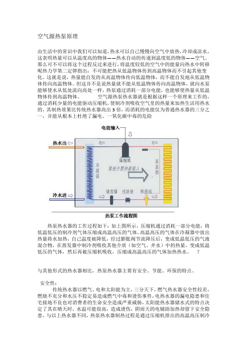
空气源热泵热水器就是根据这样一个原理来工作的,通过消耗少量的电能驱动压缩机,使制冷剂吸收空气里的热量来加热生活用热水的,其制热效果比传统热水器高出3倍,而消耗的电能仅为普通热水器的三分之一,并能从根本上杜绝了漏电、一氧化碳中毒的危险热泵热水器的工作过程如下:如上图所示,压缩机通过消耗一部分电能,将低温低压的制冷剂气体压缩成高温高压的气体,高温高压的气体在冷凝器中放出热量将水加热,自己温度被降低,经过膨胀阀节流降压后,变成低温低压的气液混合物,在蒸发器中制冷剂吸收其他介质(如空气、井水)中的热量,变成低温低压的气体,然后再被压缩机吸收,压缩成高温高压的气体加热热水。
?与其他形式的热水器相比,热泵热水器主要有安全、节能、环保的特点。
安全性:传统热水器以燃气、电和太阳能为主,三分天下,燃气热水器安全性较差,燃烧不充分和水压不稳定易造成燃气中毒和烫伤事件,电热水器的漏电隐患和住宅接地不良也对消费者的生命安全造成严重威胁,太阳能热水器储水式的特点决定了其在晴天时,水温可能很高,造成烫伤,阴雨天的电辅助加热却留下安全隐患,与以上热水器不同,热泵热水器制热过程是通过压缩机排出的高温高压制冷剂气体加热水罐中的水,电主要用于压缩机,制热后的气体通过外盘式的盘管与搪瓷水罐中的水交换热量,水电完全分离,这样,既不存在漏电隐患,省去了防漏电的烦恼,也避免了电加热管表面温度高,易结垢并影响加热效率的弊端,真正作到绝对安全。
水源热泵控制器说明书
东莞市正帝新能源科技有限公司产品规格书名称:水源热泵控制器型号:K80B(以单系统为例)水源热泵热水机控制器技术规格书一、概述本控制器适用于单压缩机(单相/三相),水源循环式热泵热水机组。
控制器由主板,室内操作线控器组成。
具有性能可靠,功能先进,用户设置灵活,外型美观保护功能齐全等特点。
二、主要技术参数1,使用条件◇运行电压:AC220V/380V±10%,50Hz±1Hz.◇运行环境温度:-20~+75℃◇储存温度:-30~+80℃◇相对湿度:0~95%RH2,温度控制精度:± 1℃3,控制器符合 GB4706.1-1998 《家用和类似用途电器的安全第一部分:通用要求》GB4706.32-1996 《家用和类似用途电器的安全热泵、空调器和除湿机的特殊要求》GB18430. 2-2001 《蒸汽压缩循环冷水(热泵)机组户用和类似用途的冷水(热泵)机组》抗干扰度符合GB4343.2-1999印刷电路板符合GB4588.1和GB4588.2的规定爬电距离符合国际CE认证要求。
三、控制器主要功能1, 制热、制冷运行2, 可显示水箱温度及设置温度,具有查询功能(可查询进出水温度,环境温度,排气温度等)3, 掉电自动记忆各种参数,来电后可自动恢复运行4, 掉电后时钟仍然运行,省掉每次停电重新调整的烦恼5, 错峰用电功能,在24小时内可实现两段定时开关机6, 各种参数设定及修正7, 密码设定8, 防冻保护功能9, 超大液晶屏显示(全透液晶屏蓝底白字)10,具有完善的保护功能11,故障代码显示查询(可查询压机不开或压机停的故障原因)及键盘锁功能13,三相电缺相,逆相保护14,在没有面板(或面板损坏)的情况下,系统能自动识别并自动按已设参数运行四、主控板1,控制板输入1.1,单系统K80B(从上到下):冰点—远程控制信号(在开机状态下,接通-按设定温度开停断开-待机)水压—水源水水流开关高压—高压开关低压—低压开关水流—循环水水流开关高水位—高水位探针中水位—中水位探针低水位—低水位探针公共端—以上开关信号的公共端A—三相交流电A相B—三相交流电B相C—三相交流电C相1.2,双系统K90B(从上到下):联动—备用冰点—远程控制信号(在开机状态下,接通-按设定温度开停断开-待机)水压—水源水水流开关水流—循环水水流开关高压1—压机1高压开关高压2—压机2高压开关低压1—压机1低压开关低压2—压机2低压开关高水位—高水位探针中水位—中水位探针低水位—低水位探针公共端—以上开关信号的公共端A—三相交流电A相B—三相交流电B相C—三相交流电C相2,控制板火线(A相)输出2.1,单系统K80B(从左到右):out1—压缩机out2—四通阀out3—循环泵out4—补水阀out5—水源泵out6—泄压阀(喷液阀)out7—曲轴加热out8—电热out9—增焓阀out10—供水泵2.2,双系统K90B(从左到右):out1—电热out2—循环泵out3—水源泵out4—压缩机1out5—压缩机2out6—四通阀out7—补水阀out8—泄压阀(喷液阀)out9—曲轴加热out10—增焓阀3,控制板温度输入3.1 单系统K80B(从右到左):水箱—水箱温度【循环水进水温度】A1盘管—盘管温度环境—室外环境温度排气—排气温度回水—【水源水(井水)进水温度】A6出水—出水温度【循环水出水温度】A5回气—回气温度电流—【水源水(井水)出水温度】A83.2 双系统K90B(从右到左):水箱—水箱温度【循环水进水温度】出水1—出水1温度【循环水出水温度】出水2—出水2温度【水源水出水温度】盘管1—压机1盘管温度盘管2—压机2盘管温度排气1—压机1排气温度排气2—压机2排气温度环境—室外环境温度回气1—压机1回气温度回气2—压机2回气温度回水—回水温度【水源水进水温度】电流1—压机1电流电流2—压机2电流五、操作面板说明1,控制面板图2,操作操作面板上电,蜂鸣器长鸣一声,显示器显示,背光微亮,此时触摸按键被锁定,触摸任何按键均无效。
水源热泵中央空调控制器技术手册
AT4 入水温度
模拟:NTC
用于入水 1 水温异常保护
-19~99℃
AT5 备用
DI1 流量开关
开关:闭合正常 断流无水保护
水泵开启 1 分钟后检测,检测延时 10 秒
DI2 电源保护
开关:闭合正常 用于外接电源保护信号输入 检测延时 3 秒,不可恢复
DI3 送风机过载
开关:闭合正常 用于送风机过载检测
*﹑GB4706.1-2005 《家用和类似用途电器的安全 (第一部分:通用要求)》 *﹑GB4706.32-2005《家用和类似用途电器的安全 (热泵、空调器和除湿机的特殊 要求)》 *﹑GB18430.2-2001《蒸气压缩循环冷水(热泵)机组 户用和类似用途的冷水(热 泵)机组》 *﹑振动试验:频率 50Hz,加速度 2.5g; *﹑印刷线路板符合 GB4588.1 和 GB4588.2 的规定; *、电磁兼容性符合 GB4343.2-1999 的要求。
“定时”键翻看参数,按“风速”键退出查看功能。
LCD 手操器显示传感器名称与参数表
序号
传感器名称
显示代码
说明
1 回风温度传感器
h0
准确显示范围:-19℃~99℃;
2 室内盘管 1 温度传感器
h1
准确显示范围:-19℃~99℃;
3 室内盘管 2 温度传感器
h2
准确显示范围:-19℃~99℃;
4 入水温度传感器
7、
开室内风机
关机结束
8、
检测电加热开启条件
9、
开电加热
10、
开机结束
3.3 电加热器投入运行:
电加热分三级控制。至少间隔 30 秒,按照条件投入电加热运行。
AHCU型风冷热泵控制器使用手册2
型风冷热泵模块机组控制器是第三代控制器。
新一代控制器软件上做了很大的改动,进一步提高了智能化程度,运行管理更加具有人性化,除霜更加有效,抗干扰能力更强。
型风冷热泵模块机组其控制器在软件上可分为主模块和子模块而硬件结构完全一样,方便用户使用。
主模块控制器主要控制水泵、压缩机、风机、四通阀、键盘管理、显示器的管理以及输入信号采样及远程通讯,以及各子模块的管理,查询各设备的工作状态、故障分析、报警。
子模块控制器接受主模块的控制命令,完成对压缩机、风机、四通阀的控制,以及输入信号采样,采用485通讯方式,可方便组成现场控制网络。
一. 主要性能指标1-1.输入模拟量:①进水温度 -30℃80℃分辩率0.2℃②出水温度 -30℃80℃分辩率0.2℃③冷排1温度 -30℃80℃分辩率0.2℃④出水2温度 -30℃80℃分辩率0.2℃⑤冷排2温度 -30℃80℃分辩率0.2℃⑥环境温度 -30℃80℃分辩率0.2℃1-2.输入开关量:①上/下班开关⑥系统2高压保护②靶流开/关信号⑦系统2低压保护③系统1高压保护⑧系统2排气温度保护④系统1低压保护⑨风盘联动⑤系统1排气温度保护1-3.输出控制对象:①压缩机1 ⑦水泵②风机1 ⑧报警③四通阀1 ⑨辅助电热器④压缩机2⑤风机2⑥四通阀2二.主要技术特点●主模块控制器最多可带6台子模块,采用485通讯。
●每个模块的两个制冷(制热)系统独立控制,除霜过程独立进行。
●采用了多事件触发记忆,优化排序的程序结构,使机组运行及管理更加完善,更具有人性化特点。
●控制机组启停采用新型算法,减轻系统的超调和欠调,使机组运行平稳,满足制热及制热要求。
●压缩机采用实时无序轮换工作,保证压缩机均衡工作。
●除霜过程采用了多变量、多模式自修正的智能控制,使除霜更加有效,提高了机组运行效率。
●控制参数可在线设定,具有断电保护功能,停电后常数不丢失。
●各模块参数和设备运行状态采用循环显示方式,键盘中断,查找迅速,显示稳定。
热泵操作手册6页word
为使操作人员正确使用热泵,避免操作失误引起意想不到的事故或故障,特编写《热泵操作手册》。
一.盘面1.1外观1.2构成控制盘面由触摸屏、操作按钮及蜂鸣器构成。
二.键盘操作部分三.触摸屏触摸屏可以显示运转状态、数值数据及故障内容,并可以更改各种设定。
画面共有15个,分以下6种。
(1)流程画面……在热泵流程图上显示模拟量及动作状态。
(1个)(2)运转曲线画面……将各种模拟量用曲线显示出来。
(7个)(3)状态显示画面……表示各种模拟、运转状态数据。
(2个)(4)故障显示画面……显示故障、预置报警状态。
(2个)(5)模式切换画面……进行使用模式的切换、显示。
(1个)(6)设定画面……进行各种控制参数的设定。
(2个)注:发生故障时强制切换到《故障发生》画面。
四.画面解说4.1画面切换切换画面时,使用画面上的按钮。
(1)下部按钮:跳到不同功能的首页画面。
(2)(2)上部按钮(1)下部下部按钮有以下几种:(1) 流程图:跳转到系统循环流程画面(2(3) 趋势图:跳转到曲线画面(4) 故障履历:跳转到故障一览显示画面(5) 设定:跳转到运转模式、LSV 、RSV 的选择切换画面。
4.2输入设定值输入设定值时通过弹出《数字键盘》操作进行。
设定值的输入4.3流程画面显示加热流程图、模拟量、运转模式。
点击【抽气操作】按钮,出现 三种抽气模式:自动抽气:将抽气装置设置在自动状态; 手动抽气:将抽气装置设置在手动状态;试运转抽气:将机组设置在试运转模式,抽气装置设定在手动,按真空泵。
4.4动作曲线画面显示计测、演算的模拟数据曲线。
数据按1分钟为一个周期采集一次。
4.5状态画面(1)状态显示1(模拟量显示画面) 表示各种模拟数据。
显示内容如下所示。
(2)状态显示2(运转状态画面)显示各种运转状态数据。
4.6故障显示(1)故障显示画面故障发生时,自动弹出故障画面。
本画面在故障主要原因消除后,按【操作选择键】的确认键。
滚动冷却器和热泵控制器(CGA CXA RAUS RAUX CGCM CXCM)操作指南说明书
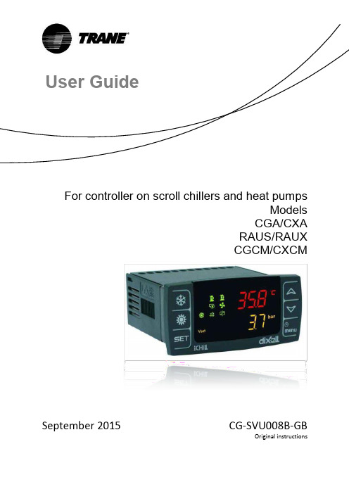
For controller on scroll chillers and heat pumpsModels CGA/CXA RAUS/RAUX CGCM/CXCMSeptember 2015CG-SVU008B-GBOriginal instructionsUser GuideTable of contentsAdvanced electronics (3)Display description (5)Buttons description and their functions (7)On/Off of the unit (9)Set point display (9)Set point editing (9)Dynamic Set Point (10)Alarm display (11)Alarm reset (11)Remote control of the unit (12)Controlling the unit remotely by free contacts (12)Controlling the unit remotely by ModBus protocol (14)Configuration parameters (15)Parameters table (16)Alarms (17)Remote display (18)WARNINGSupply the unit at least 24 hours before the initial startup to heat the compressor oil. In conditions of low water temperature, the pumps could be started in order to avoid freezing conditions. In order to avoid the breaking of heat exchangers due to water hammer, be sure to keep to water valves open. Failure to follow these instructions will void the warranty.Advanced electronicsThe control logic is able to manage air-to-water and water-to-water chillers and heat pumps with a single refrigerant circuit equipped with two scroll compressors with a proportional step regulation ac-cording inlet water temperature for air-to-water or water-to-water units.On condensing units models RAUS/RAUX, the electronic card will activate steps depending on the number of the activated digital inputs by an external thermostat or PLC.Technical SpecificationsPower supply: 24V AC/DCDigital inputs: 5 free voltageAnalog inputs: 3 NTC + 1 configurable: 0÷5V, 4÷20mA, NTCAnalog outputs Opto-Insulated: 4 configurable: 0÷10V signal, external relay driving Relay outputs: 5 x 5(2) A @ 250V SPST + 1 open collector 12Vdc 40mA maxRemote terminalSerial outputs: 1 RS485 slave with Modbus communication protocol (only with adaptor)Display descriptionThe LED display allows you to monitor and change the status of the unit, using the 6 buttons on the keypad.Home screenPress the UP and DOWN keys on the Home screen, to view the following values:"Pb1": Displays the water temperature at the exchanger inlet air-conditioning"Pb2": Displays the temperature of the water leaving the exchanger of air-conditioning"Pb4": Displays the outside air temperature (only for air-to-water units if present)"Pb3": Displays the condensing pressure in cooling mode and the evaporating pressure in heating mode“Pb4”: Displays the temperature of the water leaving the exchanger of source side (only for water-to-water units if present).and buttons allow you to activate operation model in summer and winter.The display shows “OnC”when the unit is on and in chiller mode.The display shows “OnH” when the unit is on and in heat pump mode.The display shows “OFF” when the unit is OFF.Description of the other icons on the display:Buttons description and their functionsThe controller is provided with six buttons to interact with user and installer parameters. Here below the description of the accessible operations through the buttons.Some controller functions are available through pressing multiple keys simultaneously. The following are the combinations accepted by the controller.++On/Off of the unitPressing or for about 3 seconds will switch on the unit in chiller or heat pump mode. During these 3 seconds, the selected mode led flashes.To change operating mode (i.e. to switch from chiller to heat pump mode) you must go through the standby mode first.If the controller is on, the extended pressure on the button of the current mode (chiller or heat pump) forces the unit on standby.In standby mode, you can still to enter in menu to change the parameters.Alarm management is enabled also in standby mode; alarms that occur are equally shown.Set point displayBy pressing and releasing the button, you will see the setpoint value, SetC (set chiller) if the unit is in chiller mode, or SetH (set heat pump) if the unit is in heat pump mode.By pressing and releasing the button when the unit is in standby mode, it is possible to dis-play both set points.Set point editing1. Press the key at least for 3 seconds;2. The set point will start blinking;3. To modify set point value, press and ;4. Press the key, or wait for the timeout to save the new value and to quit from program-ming;Dynamic Set PointEnabling the Dynamic Set Point and setting the appropriate parameters to increase or decrease the set point and the range of outdoor temperatures in which this feature must be active. Refer to the Parameters table (“SD” parameters) to view the setpoints the controller will continuously change ac-cording to a proportional law.With this function you can change the set point in order to ensure, with changing external conditions, increased comfort or higher efficiency of the unit.Example about the increase in efficiency achieved by enabling this function:The Dynamic Set Point is available only for air-to-water versions equipped with external air probe.Alarm displayEnter to the function menu:1. Select “ALrM” function using or ;2. Press and release ;3. The pressure on or allows to show active alarms.Press the Menu key or wait for the timeout, to exit this view.Alarm reset1. Enter to the function menu;2. Select the function “ALrM”;3. Press ; lower display shows the alarm while the upper display shows the label rSt if thealarm is resettable, or NO if it isn’t. Using or you can slide and show all active alarms;4. Press on the label rSt to reset alarm and pass to the next;5. Press the Menu key or wait for the timeout, to exit this view.Remote control of the unitIt is possible to control the unit remotely with three different methods:∙Free contacts on the user terminal (X)∙ModBus protocol on RS485 slave∙Remote keypadControlling the unit remotely by free contactsOn the X user terminal there are four free terminals where you can connect any type of temperature control device able to provide a current pulse to close the relay for the unit activation.The terminals are those with the numbers 6, 20, 22B, 23 and 29, on the X user terminal. Always refer to the wiring diagram included. This contact is generally a normally open contact.With these contacts you can enable remote On/Off, S/W change.To enable the remote S/W changing you need modify CF28.On the same terminal are also available free contacts for external reporting of general alarm.Controlling the unit remotely by ModBus protocolOn the control device installed on the unit, an input is available for serial connection on RS485 port with ModBus protocol, to use this type of connection it is necessary a TTL/RS485 adaptor.Refer to the wiring diagram below, observing a bus type connection to avoid creating star connections. You can use the master and slave RS485 port, depending on the location of the instrument in the net-work.To connect to the devices to be controlled simply use two minimum cross-section of 0.5 mm2 plus screen, use the input GND only for communication problems.Configuration parametersController parameters grouped in functional folders (CF = configuration, CO = compressor…) with a specific label each. The generic group ALL contains all controller parameters.There are 3 different levels: user level without password and the other two, only for authorized techni-cian, available with password.How to enter “Pr1”:1. Press and for a few seconds;2. Icons will flash and upper display shows “ALL” (generic parameters group);3. Slide the parameters groups using and ;4. Select the group that contains parameters to edit. Pressing the set button, you can enter in theparameters list of that group.Lower display shows parameter label and the upper its value.5. Select parameter;6. Press the key to enable editing;7. You can edit the value using or ;8. Press the button to save the new value and to move to the next;9. To exit, press the key, when you are in parameters viewing (not during the change withblinking value), or wait for the timeout.NOTE:The new value is also saved when you quit because of timeout, without pressing the button.Parameters tableThe parameters are grouped by macro-groups, as follows:AlarmsThe controller is able to identify all alarms that may damage the normal operation of the unit. For each alarm code, the controller performs a given action.Below is a table with alarm codes.Remote displayThe remote terminal is connected directly to the controller connectors designed for the remote keypad, paying particular attention to the polarity of the connections.Incorrect wiring may cause serious damage to the keyboard or controller.Trane optimizes the performance of homes and buildings around the world. A business of Ingersoll Rand, the leader in creating and sustaining safe, comfortable and energy efficient environments, Trane offers a broad portfolio of ad-vanced controls and HVAC systems, comprehensive building services, and parts.For more information, visit .Trane has a policy of continuous product and product data improvement and reserves the right to change design and specifications without notice.© 2015 Trane All rights reservedCG-SVU008B-GB September 2015。
空气源热泵使用说明书
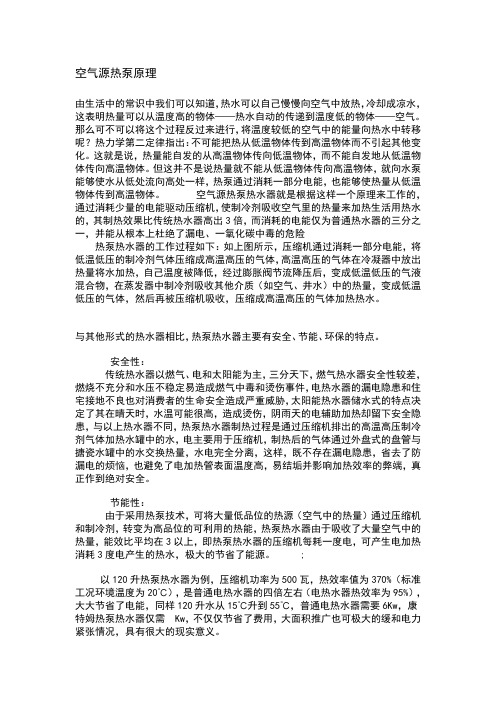
空气源热泵原理由生活中的常识中我们可以知道,热水可以自己慢慢向空气中放热,冷却成凉水,这表明热量可以从温度高的物体——热水自动的传递到温度低的物体——空气。
那么可不可以将这个过程反过来进行,将温度较低的空气中的能量向热水中转移呢?热力学第二定律指出:不可能把热从低温物体传到高温物体而不引起其他变化。
这就是说,热量能自发的从高温物体传向低温物体,而不能自发地从低温物体传向高温物体。
但这并不是说热量就不能从低温物体传向高温物体,就向水泵能够使水从低处流向高处一样,热泵通过消耗一部分电能,也能够使热量从低温物体传到高温物体。
空气源热泵热水器就是根据这样一个原理来工作的,通过消耗少量的电能驱动压缩机,使制冷剂吸收空气里的热量来加热生活用热水的,其制热效果比传统热水器高出3倍,而消耗的电能仅为普通热水器的三分之一,并能从根本上杜绝了漏电、一氧化碳中毒的危险热泵热水器的工作过程如下:如上图所示,压缩机通过消耗一部分电能,将低温低压的制冷剂气体压缩成高温高压的气体,高温高压的气体在冷凝器中放出热量将水加热,自己温度被降低,经过膨胀阀节流降压后,变成低温低压的气液混合物,在蒸发器中制冷剂吸收其他介质(如空气、井水)中的热量,变成低温低压的气体,然后再被压缩机吸收,压缩成高温高压的气体加热热水。
与其他形式的热水器相比,热泵热水器主要有安全、节能、环保的特点。
安全性:传统热水器以燃气、电和太阳能为主,三分天下,燃气热水器安全性较差,燃烧不充分和水压不稳定易造成燃气中毒和烫伤事件,电热水器的漏电隐患和住宅接地不良也对消费者的生命安全造成严重威胁,太阳能热水器储水式的特点决定了其在晴天时,水温可能很高,造成烫伤,阴雨天的电辅助加热却留下安全隐患,与以上热水器不同,热泵热水器制热过程是通过压缩机排出的高温高压制冷剂气体加热水罐中的水,电主要用于压缩机,制热后的气体通过外盘式的盘管与搪瓷水罐中的水交换热量,水电完全分离,这样,既不存在漏电隐患,省去了防漏电的烦恼,也避免了电加热管表面温度高,易结垢并影响加热效率的弊端,真正作到绝对安全。
NONI 单系统热泵热水机控制器操作说明书
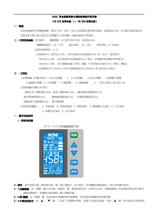
NONI 單系統熱泵熱水機控制器操作說明書(NI- K70為單系統)( NI- K90為雙系統)一、概述本控制器適用於單雙壓縮機(單相/三相),風冷,直出水或循環式熱泵熱水機組。
控制器由主板,室內操作線控器組成。
品質性能可靠,功能先進,用戶設置靈活,外型美觀,保護功能齊全等特點。
二、主要技術參數1,使用條件運轉電壓:AC220V/380V±10%,60/50Hz±1Hz.運轉環境溫度:-20~+75℃儲存溫度:-30~+80℃相對濕度:0~95%RH2,溫度控制精度:+/- 1℃3,控制器符合GB4706.1-1998 《家用和類似用途電器的安全第一部分:通用要求》GB4706.32-1996 《家用和類似用途電器的安全熱泵、空調器和除濕機的特殊要求》GB18430. 2-2001 《蒸汽壓縮迴圈(熱泵)機組戶用和類似用途的冷水(熱泵)機組》抗幹擾度符合GB4343.2-1999印刷電路板符合GB4588.1和GB4588.2的規定三、主控板1,控制板輸入保護INPUT 1.低水位開關 2. 中水位開關 3.高水位開關 4.低壓壓力開關5.高壓壓力開關6. 水流開關7. 水壓開關8. 連動開關9. 三相交流電A相,B相,C相2,控制板輸出接點OUTPUT循環水泵(接點電流20A) 風扇(接點電流20A) 輔助電熱(接點電流8A)補水閥(接點電流8A) 壓縮機(接點電流8A) 四通閥(接點電流8A)曲軸加熱(接點電流8A) 電子膨脹閥3,控制板測量輸入 A. 水箱溫度 B. 蒸發器溫度 C. 環境溫度 D. 壓縮機吐出溫度 E. 出水溫度F. 低壓回流溫度G. 回水溫度四、操作面板說明1,控制面板圖2,操作操作面板送電,蜂鳴器長鳴一聲,顯示器顯示,背光微亮,此時觸摸按鍵被鎖定,按任何按鍵均無效。
2.1按鍵解鎖:按“開關”鍵約3秒鐘,當聽到“嘟”聲後移開手指,此時背光高亮,按鍵被解鎖,沒有鎖鍵符號(當約60秒鐘無按鍵操作,按鍵會自動被鎖定,顯示鎖鍵符號)。
空气源热泵控制系统手册

空气源热泵控制系统手册目录1. 引言2. 系统概述3. 控制面板功能4. 使用说明5. 故障排除6. 常见问题解答7. 联系方式1. 引言本手册为空气源热泵控制系统的用户提供详细的操作指南和故障排除方法。
请仔细阅读本手册,以确保正确操作系统并能及时解决可能出现的问题。
2. 系统概述空气源热泵控制系统是一种用于控制和管理热泵设备的智能系统。
它采用先进的传感器和控制器,能够监测和调节室内温度、湿度等参数,并自动控制热泵的工作状态以达到预设的舒适条件。
3. 控制面板功能系统的控制面板具有以下主要功能:- 显示当前室内温度和湿度- 设置目标温度和湿度- 调整热泵工作模式和风速- 查看当前系统状态和运行时间4. 使用说明4.1 启动和关机按下控制面板上的电源按钮,系统将启动并开始运行。
要关机,再次按下电源按钮。
4.2 设置温度和湿度按下温度和湿度调节按钮,通过向上或向下箭头调整目标温度和湿度。
4.3 调整工作模式和风速使用工作模式和风速调节按钮,选择所需的工作模式和风速。
系统支持自动、制冷、制热和通风工作模式,以及低、中、高三个风速档位。
5. 故障排除5.1 系统无法启动或无法正常工作请检查电源是否接通,并确保断路器未跳闸。
如果问题仍然存在,请联系我们的客户支持部门。
5.2 温度和湿度显示不准确可能是传感器故障或传感器放置位置不正确。
请联系我们的客户支持部门获取更多帮助。
6. 常见问题解答Q: 系统不能自动调整温度,怎么办?A: 请先检查系统设置中的温度调整范围是否正确,然后尝试重新启动系统。
Q: 为什么制冷模式下没有冷风出来?A: 请检查热泵的冷却剂是否不足,或者与热泵有关的其他问题。
如问题仍然存在,请联系我们的客户支持部门。
7. 联系方式如需进一步帮助或有其他问题,请联系我们的客户支持部门。
- 客户支持热线:。
热泵控制器

主要功能
●热泵/单冷/单热机型可选; ●可扩展到16个模块; ●电子膨胀阀适应多种复杂工况; ●根据负荷大小智能控制开机台数; ●制热模式下自动除霜; ●三级防冻功能; ●支持独立风道,双风机,单风道选择; ●模块运行时间均衡功能; ●集成缺错相保护; ●控制辅助电加热。
主要分类
热泵控制器主要分类有:暖通空调控制器、热泵烘干控制器、超低温空气源热泵控制器、恒温恒湿控制器、 热泵模块机控制器、除湿机控制器、水地源空气能热泵控制器、热泵热水控制器、热泵螺杆机控制器等等。
热泵控制器
仪器设备
01 组成部分
03 主要分类 05 发展方向
目录
02 主要功能 04 应用产品
热泵控制器,英文名:Heat pump controller,顾名思义就是用来控制空气能热泵机组的核心大脑,用于 分解和执行各种命令,并对命令进行监督及反馈,为空气能热泵机组运行提供安全稳定的保障。
组成部分
热泵控制器是由指令寄存器,程序计数器和操作控制器三个部件组成。
热泵控制器(Heat pump controller)是整个CPU的指挥控制中心,由指令寄存器 IR(InstructionRegister)、程序计数器PC(Program Counter)和操作控制器0C(OperationController)三个 部件组成,对协调整个电脑有序工作极为重要。有两种由于设计方法不同因而结构也不同的控制器:组合逻辑控 制器和微程序控制器。它根据用户预先编好的程序,依次从存储器中取出各条指令,放在指令寄存器IR中,通过 指令译码(分析)确定应该进行什么操作,然后通过操作控制器OC,按确定的时序,向相应的部件发出微操作控制 信号。操作控制器OC中主要包括节拍脉冲发生器、控制矩阵、时钟脉冲发生器、复位电路和启停电路等控制逻辑。
风冷热泵机组操作手册操作手册(客户版)
(风冷热泵机组)适用于FTA-US-80W-1HB富田空调冷冻设备有限公司地址:上海市光中路488号电话:传真:水冷机组操作说明一、按键定义说明:2. 人机画面分类: 人机画面可分成四类。
➢ 第一类画面:起始欢迎画面,即开机时显示的画面。
➢ 第二类画面:主监视画面。
主要参数的监视。
以及开、关机的操作。
➢ 第三类画面:主菜单画面。
在该页可选择进入相应的参数画面。
➢ 第四类画面:参数设定、显示画面。
用于作参数的设定或显示机组的运行信息。
二、 操作说明:步骤A :画面切换操作点击上下方向键来切换上下画面。
步骤B :参数(密码)调整步骤 1. 首先进入欲调整之参数画面。
2. 点击SET 键。
3. 点击〔ENT 〕输入键跳转至需要设定的参数。
4. 使用数字键或者上下键输入数值,按左右方向键切换输入位置。
5. 按〔ENT 〕确认输入参数。
6. 若输入错误按(ESC )键退出即可。
SET 键用于进入输入参数方向键:用于切换画面和参数设定切换指示灯:电源指示,运行指示,报警指ENT :确认键。
输入数值后,按此键将执行输入操作。
ESC :退出所设定的数值启停键:用于启动停止机组。
步骤C:开关机操作1.在任意画面按启动按钮即可进行开机操作2.在任意画面按停机按钮即可进行开机操作注:以下界面部分若有改动,恕不另行通知!以控制器上的实际界面为准!三、重要人机画面说明:控制器启动后,首先显示以下欢迎画面。
首页——欢迎画面。
显示上海富田空调电话信息。
在欢迎画面按向下键即可进入主显示选择画面主显示画面(目录画面): 显示操作画面提示,按向右键进入用户设定画面;按向左键进入系统设定画面;按向下键进入主显示画面内容。
主显示画面(参数显示画面): 显示机组各类模式设定内容,开机模式,是指自动开关机还是手动开关机;工作模式显示;控制模式显示,遥控或远控;开机间隔时间用于显示开机间隔是否已到。
四.人机画面分类说明运转信息画面系列本页为运转信息(监视画面),显示当前日期和时间,显示出水温度,环境温度以及盘管1出水温度。
空气源热泵使用说明书

空气源热泵原理由生活中的常识中我们可以知道,热水可以自己慢慢向空气中放热,冷却成凉水,这表明热量可以从温度高的物体——热水自动的传递到温度低的物体——空气。
那么可不可以将这个过程反过来进行,将温度较低的空气中的能量向热水中转移呢?热力学第二定律指出:不可能把热从低温物体传到高温物体而不引起其他变化。
这就是说,热量能自发的从高温物体传向低温物体,而不能自发地从低温物体传向高温物体。
但这并不是说热量就不能从低温物体传向高温物体,就向水泵能够使水从低处流向高处一样,热泵通过消耗一部分电能,也能够使热量从低温物体传到高温物体。
空气源热泵热水器就是根据这样一个原理来工作的,通过消耗少量的电能驱动压缩机,使制冷剂吸收空气里的热量来加热生活用热水的,其制热效果比传统热水器高出3倍,而消耗的电能仅为普通热水器的三分之一,并能从根本上杜绝了漏电、一氧化碳中毒的危险热泵热水器的工作过程如下:如上图所示,压缩机通过消耗一部分电能,将低温低压的制冷剂气体压缩成高温高压的气体,高温高压的气体在冷凝器中放出热量将水加热,自己温度被降低,经过膨胀阀节流降压后,变成低温低压的气液混合物,在蒸发器中制冷剂吸收其他介质(如空气、井水)中的热量,变成低温低压的气体,然后再被压缩机吸收,压缩成高温高压的气体加热热水。
与其他形式的热水器相比,热泵热水器主要有安全、节能、环保的特点。
安全性:传统热水器以燃气、电和太阳能为主,三分天下,燃气热水器安全性较差,燃烧不充分和水压不稳定易造成燃气中毒和烫伤事件,电热水器的漏电隐患和住宅接地不良也对消费者的生命安全造成严重威胁,太阳能热水器储水式的特点决定了其在晴天时,水温可能很高,造成烫伤,阴雨天的电辅助加热却留下安全隐患,与以上热水器不同,热泵热水器制热过程是通过压缩机排出的高温高压制冷剂气体加热水罐中的水,电主要用于压缩机,制热后的气体通过外盘式的盘管与搪瓷水罐中的水交换热量,水电完全分离,这样,既不存在漏电隐患,省去了防漏电的烦恼,也避免了电加热管表面温度高,易结垢并影响加热效率的弊端,真正作到绝对安全。
- 1、下载文档前请自行甄别文档内容的完整性,平台不提供额外的编辑、内容补充、找答案等附加服务。
- 2、"仅部分预览"的文档,不可在线预览部分如存在完整性等问题,可反馈申请退款(可完整预览的文档不适用该条件!)。
- 3、如文档侵犯您的权益,请联系客服反馈,我们会尽快为您处理(人工客服工作时间:9:00-18:30)。
热泵控制器使用说明书:
一、检测功能:
模拟量:室外井水进水温度、井水出水温度、室内循环出水温度、循环进水温度和室内环境温度、室外环境温度。
开关量:室外井水水流开关、室内循环水水流开关、热泵故障。
这三个开关量均应为常开无源触点,动作时触点闭合。
二、控制输出:
室外井水泵控制、室内循环泵控制、热泵控制、加引水控制、制冷控制、热泵自加热控制等6路开关量输出,其中室外井水泵控制、室内循环泵控制、热泵控制具有公共控制输入端(L),加引水控制、制冷控制、热泵自加热控制各自独立输出。
三、控制功能
1、设置参数:室温、制热/制冷、室内循环出水上限、室内循环出水下限、室温偏差、当前年、月、日、时、分、秒、星期等。
2、制热控制:
⑴当实际室内温度<设定室内温度—偏差值,且室内循环出水温度<室内循环出水温度低限时,能够开始制热功能,首先控制井水泵启动,延时后控制室内循环泵启动,若在室内循环泵启动后30秒内井水水流开关和室内循环水水流开关均能够闭合,则能够顺利启动热泵。
若井水水泵启动后2分钟内检测不到井水水流开关闭合,会控制“加引水”开关闭合5秒钟,给室外井水泵加引水,若10分钟仍旧不能检测不到井水水流开关闭合,则停止室外井水泵和室内循环泵工作,液晶提示“室外井水故障”,需检查排除故障后,重新给设备送电后运行。
若运行过程中检测到热泵故障信息,则顺序停止热泵、井水泵和循环泵,液晶提示“压缩机故障”,需检查排除故障后,重新给设备送电后运行。
⑵当实际室内温度>设定室内温度+偏差值,或室内循环出水温度>室内循环出水温度上限时,顺序停止热泵、井水泵和循环泵工作,停止制热工作。
⑶当室外环境温度<4℃且室内循环进水温度<4℃时,自动启动压缩机自加热。
⑷在每天5:00~8:00、17:00~22:00,室内温度控制按照设定室内温度+0.5℃运行。
3、制冷控制:
当通过按键设置为“制冷”状态时,制冷控制开关闭合。
若实际室内温度>设定室内温度+偏差值,且循环出水温度>5℃,开始顺序启动井水泵、室内循环泵和热泵;若实际室内温度<设定室内温度-偏差值,则顺序停止热泵、室外井水泵、室内循环泵工作。
若井水水流开关、室内循环水水流开关不能正常闭合或热泵故障,故障提示同制热功能。
系统具有自动启动和停机功能,也可以通过按键手动停机和启动。
四、按键:
控制器具有4个操作按键,分别为:设置、+、—、确认,这四个键均为多功能键,在不同显示界面时具有不同功能。
五、显示界面:
液晶显示具有自动关闭功能,当最后一次按键操作1分钟后自动关闭液晶背光电源,显示变暗;在显示变暗时,按任意按键可以使开液晶背光,使显示变亮。
1. 通电显示界面
2. 人工启动界面:在上述通电显示界面下,按“+”键进入人工启动界面
按“设置”键启动供暖系统,按“确认”键退出该界面,返回界面1
3. 运行界面。
运行界面包含两个运行参数显示界面,显示六个检测温度值、当前时间及制冷/制热方式。
(1)运行界面1:
(2)运行界面2:
若出现某个温度值显示为:<XX.X度时,可能是测量该温度的传感器断线。
4. 人工停止供暖界面。
在上述运行界面时,按“+”键可以是控制器进入人工停止供暖界面。
按“设置”键停止供暖系统,按“确认”键退出该界面,返回运行界面1 5. 设置界面。
在运行界面下,按“设置”键可以进入工作参数设置界面,来设置欲达到的室温、温度偏差、自动工作时间区间、当前的日期、时间、星期。
设置界面有3幅,可以通过“确认”键切换。
(1)设置界面1:
请设您需要的参量室温设定:XX.X℃模式设定: 制热
按“+”键可以增加温度,按“—”键减小温度,每按一下变化0.5℃。
温度修改正确后按一下“设置”键进入“模式设定”,按“+”或“—”键使工作模式在“制热”与“制冷”间转换,选择“制冷”模式时,控制板上“制冷”指示灯亮,制冷控制开关闭合。
再按“设置”键或“确认”键都进入密码输入界面:
若不想修改其它参数设置,不需调整密码值, 按“确认”键返回运行界面。
若需要设置其它参数,必须修改密码,默认密码为“211”。
在第一个数字闪烁时,按“+”或“—”键修改为“2”,然后按“设置”键,第二个数字闪烁,按“+”或“—”键修改为“1”,再按“设置”键,第三个数字闪烁,按“+”或“—”键修改为“1”,按“设置”或“确认”键均可以进入参数设置界面2:
(2)设置界面2:
该界面设置系统当前日期和时间。
按“+”或“—”键修改当前闪烁的参数,调整正确后按“设置”键进入下一个参数。
若希望全天运行则可以将自动工作区间的两个时间设置为相同即可。
“时间”项是指当前时间设置,用于长时间运行后调整时间误差。
最后一个参数调整完毕后,按“设置”或“确认”键均可以进入参数设置界面3:
(3)设置界面3 Array
“出水温度范围”用于设置制热模式时室内循环水出水的温度范围,当循环出水温度超过上限时,停止热泵工作,延时停止井水泵和室内循环泵;当循环出水温度低于下限时,启动系统工作。
“室温偏差”是指控制室温在设定“室内温度”基础上上下波动的范围。
如设定“室内温度”为20℃,“室温偏差”设置为1.0,则热泵系统会在“环境温度”超过21℃时停机,在“环境温度”低于19℃时启动运行。
“自启动时间”是指系统在每次通电后自动延时一定的时间后自动投入系统工作。
参数设置完毕后,按按“设置”或“确认”键均可以返回运行界面1。
六、端子接线图:
控制器接线板左右两侧后有30个接线端子,功能如下:
RB XH JS
开关状态检测接线图
室外循环水泵控制室内循环水泵控制热泵控制
L
RB XH JS
水泵、压缩机控制输出接线图
加引水
热泵自加热
制冷控制
独立触点输出量接陷入
6个控制输出均为继电器常开触点,触点容量为最大交流220V ,7A ,如控制输出功率较大应外加接触器控制。
