KST5401MTF中文资料
MMBT5401-TP;中文规格书,Datasheet资料
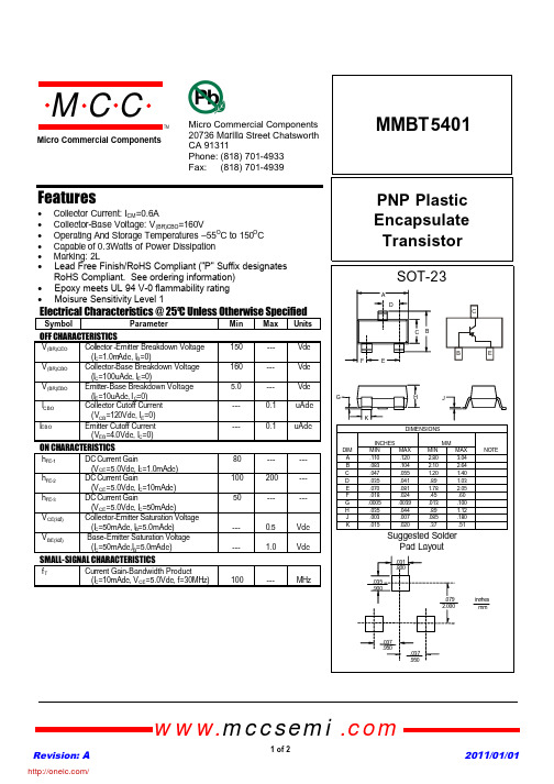
MMBT5401PNP Plastic Encapsulate TransistorFeatures• Collector Current:I CM =0.6A• Collector-Base Voltage:V (BR)CBO =160V• Operating And Storage Temperatures –55O C to 150O C • Capable of 0.3Watts of Power Dissipation • Marking:2LElectrical Characteristics @ 25OC Unless Otherwise SpecifiedSymbol ParameterMin Max Units OFF CHARACTERISTICSV (BR)CEO Coll e ctor -Emitter Breakdown Voltage (I C =1.0m Adc,I B =0)150--- Vdc V (BR)CBO Collector-Base Breakdown Voltage (I C =100uAdc,I E =0)160--- Vdc V (BR)EBO Emitter-Base Breakdown Voltage (I E =10uAdc,I C =0) 5.0--- VdcI CBO Collector Cutoff Current (V CB =120Vdc,I E =0)---0.1uAdcI EBOEmitter Cutoff Current (V EB =4.0Vdc,I C =0)---0.1uAdcON CHARACTERISTICSh FE-1DC Current Gain(V CE =5.0Vdc,I C =1.0mAdc)80------ h FE-2DC Current Gain(V CE =5.0Vdc,I C =10mAdc)100200--- h FE-3DC Current Gain(V CE =5.0Vdc,I C =50mAdc)50------V CE(sat)Collector-Emitter Saturation Voltage (I C =50mAdc,I B =5.0mAdc)---0.5Vdc V BE(sat)Base-Emitter Saturation Voltage (I C =50mAdc,I B =5.0mAdc)---1.0VdcSMALL-SIGNAL CHARACTERISTICSf TCurrent Gain-Bandwidth Product(I C =10mAdc,V CE =5.0Vdc, f=30MHz)100---MHzRevision: A 2011/01/01omp onents 20736Marilla Street Chatsworth! "# $ % ! "#Micro Commercial Componentswww.mccsemi .com1 of 2• Lead Free Finish/RoHS Compliant ("P" Suffix designates RoHS Compliant. See ordering information)• Epoxy meets UL 94 V-0 flammability rating • Moisure Sensitivity Level 1/Revision: A 2011/01/01Micro Commercial Componentswww.mccsemi .com2 of 23Ordering Information :***IMPORTANT NOTICE***Micro Commercial Components Corp. reserve s the right to make changes without further notice to any product herein to make corrections, modifications , enhancements , improvements , or other changes . Micro Commercial Components Corp . does not assume any liability arising out of the application or use of any product described herein; neither does it convey any license under its patent rights ,nor the rights of others . The user of products in such applications shall assume all risks of such use and will agree to hold Micro Commercial Components Corp . and all the companies whose products are represented on our website, harmless against all damages.***LIFE SUPPORT***MCC's products are not authorized for use as critical components in life support devices or systems without the express writtenapproval of Micro Commercial Components Corporation.***CUSTOMER AWARENESS***Counterfeiting of semiconductor parts is a growing problem in the industry. Micro Commercial Components (MCC) is taking strong measures to protect ourselves and our customers from the proliferation of counterfeit parts. MCC strongly encourages customers to purchase MCC parts either directly from MCC or from Authorized MCC Distributors who are listed by country on our web page cited below . Products customers buy either from MCC directly or from Authorized MCC Distributors are genuine parts, have full traceability, meet MCC's quality standards for handling and storage. MCC will not provide any warranty coverage or other assistance for parts bought from Unauthorized Sources. MCC is committed to combat this global problem and encourage our customers to do their part in stopping this practice by buying direct or from authorized distributors.DevicePackingPart Number-T PTape&Reel;3Kpcs/Reel/分销商库存信息: MICRO-COMMERICAL-CO MMBT5401-TP。
MMST5401贴片三极管 SOT-323三极管封装MMST5401规格参数

A,Oct,2010JIANGSU CHANGJIANG ELECTRONICS TECHNOLOGY CO., LTDSOT-323 Plastic-Encapsulate TransistorsMMST5401 TRANSISTOR (PNP)FEATURES● Complementary to MMST5551● Small Surface Mount Package● Ideal for Medium Power Amplificationand SwitchingMARKING:K4MMAXIMUM RATINGS (T a =25℃ unless otherwise noted) SymbolParameter Value Unit V CBOCollector-Base Voltage -160 V V CEOCollector-Emitter Voltage -150 V V EBOEmitter-Base Voltage -5 V I CCollector Current -600 mA P CCollector Power Dissipation 200 mW R ΘJAThermal Resistance From Junction To Ambient 625 ℃/W T jJunction Temperature 150 ℃ T stg Storage Temperature -55~+150 ℃ ELECTRICAL CHARACTERISTICS (Ta =25℃ unless otherwise specified) ParameterSymbol Test conditions Min Typ MaxUnit Collector-base breakdown voltageV (BR)CBO I C =-100µA, I E =0 -160 V Collector-emitter breakdown voltageV (BR)CEO I C =-1mA, I B =0 -150 V Emitter-base breakdown voltageV (BR)EBO I E =-10µA, I C =0 -5 V Collector cut-off currentI CBO V CB =-120V, I E =0 -50 nA Emitter cut-off currentI EBO V EB =-3V, I C =0 -50 nA V CE =-5V, I C =-1mA 50 V CE =-5V, I C =-10mA60 300 DC current gain h FE V CE =-5V, I C =-50mA50 I C =-50mA, I B =-5mA -0.5 V Collector-emitter saturation voltageV CE(sat) I C =-10mA, I B =-1mA -0.2 V I C =-50mA, I B =-5mA -1 V Base-emitter saturation voltageV BE(sat) I C =-10mA, I B =-1mA -1 V Transition frequencyf T V CE =-10V,I C =-10mA , f=100MHz 100 MHz Collector output capacitance C ob V CB =-10V, I E =0, f=1MHz 6 pF 【南京南山半导体有限公司 — 长电三极管选型资料】 【南京南山半导体有限公司 — 长电三极管选型资料】The bottom gasketThe top gasket3000×1 PCS 3000×15 PCS Label on the Reel Label on the Inner Box Label on the Outer Box QA Label Seal the boxwith the tape Seal the boxwith the tape Stamp “EMPTY”on the empty box Inner Box: 210mm ×208mm ×203m m Outer Box: 440mm ×440mm ×230mm。
凯特克液压机具技术参数
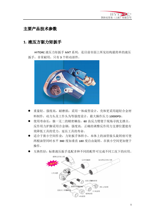
主要产品技术参数1.液压方驱力矩扳手HYTORC液压力矩扳手MXT系列,是目前市面上所见结构最简单的液压扳手,非常耐用,只有3个转动部件,●重量轻、强度高,耐磨损:采用一体成型设计,壳体更采用超轻合金材料制作,动力头及工作头为等强度设计,最大操作压力10000PSI。
●使用寿命长:独一无二的精密棘齿,60齿反力臂便于现场寻找支撑点,反作用力护脚采用合金钢,强度高。
正确的调整反作用力支撑位置能有效降低工具的受力,延长工具的寿命。
●适合于狭小空间作业:力矩扳手体积小,本体上的油管接头旋转座可使两根油管同时水平360度加垂直180度自由旋转,在狭小空间更加便于操作。
●互换性好:标准液压扳手选配多种不同的配件可完成不同工况下的应用。
●多重保护:液压力矩扳手具有多重保护功能,一旦扳手力矩值或操作压力过大,系统自动卸压,保护系统完整。
●扭矩力精确度:±3%,螺栓预紧力精确度:±10%。
●配合内六角转换套筒,可对内六角螺栓进行拆松和紧固。
●每部扳手配备手握柄,方便移动。
2 液压中空扳手STEALTH可360°x 180°旋转的油管接口双油缸设计TITAL 399材料的一体型机身非常低的载荷分散卡扣式驱动头连接设计2液压扳手专用电动泵● 以美国超高液压工具通用标准10000psi (70Mpa )为最大工作压力,配备高精度的冲油防震式压力表,扭矩输出连续均匀。
● 独特的微电脑控制系统使控制更加方便,更加精确。
● 无刷式感应电机特有马达线圈温感装置,当马达温度达到150摄氏度时电机自动停机以保护马达不受顺坏。
● 配备1.0级湿式压力表,抗震性好,精度更高。
● 具有外置可调式风扇冷却系统,对油路降温,保证液压泵可长时间往复连续工作。
根据实际工况可调整是否冷却,节约成本。
● 两级液压泵,高压时流量1升/分钟,低压时流量11.8升/分钟。
使紧固螺栓时空载或低压操作速度更快,紧固速度提升。
2N5401中文资料
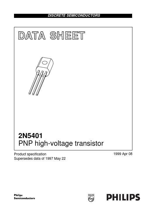
SYMBOL
PARAMETER
CONDITIONS
MIN.
ICBO
IEBO hFE
VCEsat
Cc fT F
collector cut-off current
IE = 0; VCB = −120 V
−
IE = 0; VCB = −120 V; Tamb = 100 °C
−
emitter cut-off current
OUTLINE
VERSION
IEC
REFERENCES
JEDEC
EIAJ
EUROPEAN PROJECTION
SOT54
TO-92
SC-43
ISSUE DATE 97-02-28
1999 Apr 08
5
元器件交易网
Philips Semiconductors
PNP high-voltage transistor
IC = 0; VEB = −4 V
−
DC current gain
IC = −1 mA; VCE = −5 V; see Fig.2
50
IC = −10 mA; VCE = −5 V; see Fig.2
60
IC = −50 mA; VCE = −5 V; see Fig.2
50
collector-emitter saturation voltage IC = −10 mA; IB = −1 mA
IC mA
−103
1999 Apr 08
4
元器件交易网
Philips Semiconductors
PNP high-voltage transistor
2N5401中文资料_数据手册_参数

2N5401中⽂资料_数据⼿册_参数DATA SHEETProduct speci?cationSupersedes data of 1997 May 221999Apr 08DISCRETE SEMICONDUCTORS2N5401PNP high-voltage transistorbook, halfpageM3D186PNP high-voltage transistor2N5401FEATURESLow current (max. 300mA)High voltage (max. 150V).APPLICATIONSGeneral purpose switching and amplification Telephony applications.DESCRIPTIONPNP high-voltage transistor in a TO-92; SOT54 plastic package. NPN complement: 2N5551.PINNING PIN DESCRIPTION1collector2base3emitterFig.1Simplified outline (TO-92; SOT54)and symbol.handbook, halfpage132MAM280123LIMITING VALUESIn accordance with the Absolute Maximum Rating System (IEC134).SYMBOL PARAMETER CONDITIONS MIN.MAX.UNIT V CBO collector-base voltage open emitter??160V V CEO collector-emitter voltage open base??150VV EBO emitter-base voltage open collector??5VI C collector current (DC)??300mAI CM peak collector current??600mAI BM peak base current??100mAP tot total power dissipation T amb≤25°C?630mWT stg storage temperature?65+150°CT j junction temperature?150°CT amb operating ambient temperature?65+150°CPNP high-voltage transistor2N5401THERMAL CHARACTERISTICS Note1.Transistor mounted on an FR4 printed-circuit board.CHARACTERISTICST amb =25°C unless otherwise speci?ed.SYMBOL PARAMETERCONDITIONS VALUE UNIT R th j-a thermal resistance from junction to ambientnote 1200K/WSYMBOL PARAMETERCONDITIONSMIN.MAX.UNIT I CBO collector cut-off current I E =0; V CB =?120V50nA I E =0; V CB =?120V; T amb =100°C 50µA I EBO emitter cut-off current I C =0; V EB =?4V50nAh FEDC current gainI C =?1mA; V CE =?5V; see Fig.250?I C =?10mA; V CE =?5V; see Fig.260240I C =?50mA; V CE =?5V; see Fig.250?V CEsat collector-emitter saturation voltage I C =?10mA; I B =?1mA200mV I C =?50mA; I B =?5mA500mV C c collector capacitance I E =i e =0; V CB =?10V; f =1MHz ?6pF f T transition frequency I C =?10mA; V CE =? 10V; f =100MHz 100300MHz Fnoise ?gureI C =?200µA; V CE =?5V; R S =2k ?;f =10Hz to 15.7kHz8pFPNP high-voltage transistor 2N5401Fig.2 DC current gain; typical values.handbook, full pagewidth015020050100MGD813101110102103h FEI C mAV CE = ?5 VPNP high-voltage transistor2N5401PACKAGE OUTLINEUNIT A REFERENCESOUTLINE VERSION EUROPEAN PROJECTIONISSUE DATE IECJEDEC EIAJ mm5.25.0b 0.480.40c 0.450.40D 4.84.4d 1.71.4E 4.23.6L 14.512.7e 2.54e 11.27L 1(1)2.5b 10.660.56DIMENSIONS (mm are the original dimensions)Note1. Terminal dimensions within this zone are uncontrolled to allow for flow of plastic and terminal irregularities. SOT54SC-4397-02-28AL0 2.5 5 mmscalebcDb 1L 1dE Plastic single-ended leaded (through hole) package; 3 leadsSOT54e 1e123PNP high-voltage transistor2N5401DEFINITIONSData sheet statusObjective speci?cation This data sheet contains target or goal speci?cations for product development. Preliminary speci? cation This data sheet contains preliminary data; supplementary data may be published later. Product speci?cation This data sheet contains ?nal product speci?cations.Limiting valuesLimiting values given are in accordance with the Absolute Maximum Rating System (IEC 134). Stress above one or more of the limiting values may cause permanent damage to the device. These are stress ratings only and operation of the device at these or at any other conditions above those given in the Characteristics sections of the speci?cation is not implied. Exposure to limiting values for extended periods may affect device reliability.Application informationWhere application information is given, it is advisory and does not form part of the speci?cation.LIFE SUPPORT APPLICATIONSThese products are not designed for use in life support appliances, devices, or systems where malfunction of these products can reasonably be expected to result in personal injury. Philips customers using or selling these products for use in such applications do so at their own risk and agree to fully indemnify Philips for any damages resulting from such improper use or sale.PNP high-voltage transistor2N5401Internet: /doc/eacdd8a926d3240c844769eae009581b6ad9bdd4.htmlPhilips Semiconductors – a worldwide companyPhilips Electronics N.V. 1999SCA63All rights are reserved. Reproduction in whole or in part is prohibited without the prior written consent of the copyright owner.The information presented in this document does not form part of any quotation or contract, is believed to be accurate and reliable and may be changed without notice. No liability will be accepted by the publisher for any consequence of its use. Publication thereof does not convey nor imply any license under patent- or other industrial or intellectual property rights.Netherlands: Postbus 90050, 5600PB EINDHOVEN, Bldg.VB,Tel.+31402782785,Fax.+31402788399New Zealand: 2Wagener Place, C.P.O.Box 1041, AUCKLAND,Tel.+6498494160,Fax.+6498497811Norway: Box 1, Manglerud 0612, OSLO,Tel.+4722748000,Fax.+4722748341Pakistan: see SingaporePhilippines: Philips Semiconductors Philippines Inc.,106Valero St.Salcedo Village, P.O.Box 2108MCC,MAKATI,Metro MANILA, Tel.+6328166380,Fax.+6328173474Poland: Ul.Lukiska 10, PL 04-123WARSZAWA,Tel.+48226122831,Fax.+48226122327Portugal: see Spain Romania: see Italy Russia: Philips Russia, /doc/eacdd8a926d3240c844769eae009581b6ad9bdd4.html atcheva 35A, 119048MOSCOW,Tel.+70957556918,Fax.+70957556919Singapore: Lorong 1, Toa Payoh, SINGAPORE 319762,Tel.+653502538,Fax.+652516500Slovakia: see Austria Slovenia: see ItalySouth Africa: S.A. PHILIPS Pty Ltd., 195-215Main Road Martindale,2092JOHANNESBURG, P.O.Box 7430 Johannesburg 2000,Tel.+27114705911,Fax.+27114705494South America: Al.Vicente Pinzon,173, 6th floor,04547-130S?O PAULO,SP, Brazil,Tel.+55118212333,Fax.+55118212382Spain: Balmes 22, 08007BARCELONA,Tel.+34933016312,Fax.+34933014107Sweden: Kottbygatan 7, Akalla, S-16485STOCKHOLM,Tel.+46859852000,Fax.+46859852745Switzerland: Allmendstrasse 140, CH-8027ZüRICH,Tel.+4114882741Fax.+4114883263Taiwan: Philips Semiconductors, 6F, No.96, Chien Kuo N.Rd.,Sec.1,TAIPEI, TaiwanTel.+886221342886,Fax.+886221342874Thailand: PHILIPS ELECTRONICS (THAILAND) Ltd.,209/2Sanpavuth-Bangna Road Prakanong, BANGKOK 10260,Tel.+6627454090,Fax.+6623980793Turkey: Talatpasa Cad. No.5, 80640GüLTEPE/ISTANBUL,Tel.+902122792770,Fax.+902122826707Ukraine : PHILIPS UKRAINE, 4Patrice Lumumba str., Building B, Floor 7,252042KIEV, Tel.+380442642776, Fax.+380442680461United Kingdom: Philips Semiconductors Ltd., 276Bath Road, Hayes,MIDDLESEX UB35BX,Tel.+441817305000,Fax.+441817548421United States: 811East Arques Avenue, SUNNYVALE, CA 94088-3409,Tel.+18002347381, Fax.+18009430087Uruguay: see South AmericaVietnam: see SingaporeYugoslavia: PHILIPS, Trg N. Pasica 5/v, 11000BEOGRAD,Tel.+38111625344,Fax.+38111635777For all other countries apply to: Philips Semiconductors,International Marketing &Sales Communications,Building BE-p, P.O.Box 218,5600MD EINDHOVEN, The Netherlands,Fax.+31402724825Argentina: see South AmericaAustralia: 34 Waterloo Road, NORTH RYDE, NSW 2113,Tel.+61298054455,Fax.+61298054466Austria:Computerstr. 6, A-1101 WIEN, P.O. Box 213,Tel.+431601011248, Fax.+431601011210Belarus: Hotel Minsk Business Center, Bld.3, r.1211, Volodarski Str.6,220050MINSK,Tel.+375172200733,Fax.+375172200773Belgium: see The Netherlands Brazil:see South AmericaBulgaria:Philips Bulgaria Ltd., Energoproject, 15th floor,51James Bourchier Blvd.,1407SOFIA,Tel.+3592689211,Fax.+3592689102Canada: PHILIPS SEMICONDUCTORS/COMPONENTS,Tel.+18002347381, Fax.+18009430087China/Hong Kong: 501Hong Kong Industrial Technology Centre,72Tat Chee Avenue, Kowloon Tong, HONGKONG,Tel.+852********,Fax.+852********Colombia: see South America Czech Republic: see AustriaDenmark: Sydhavnsgade 23, 1780COPENHAGEN V,Tel.+4533293333,Fax.+4533293905Finland: Sinikalliontie 3, FIN-02630ESPOO,Tel.+3589615800,Fax.+358961580920France: 51Rue Carnot, BP317, 92156SURESNES Cedex,Tel.+33140996161,Fax.+33140996427Germany: Hammerbrookstra?e 69, D-20097HAMBURG,Tel.+4940235360,Fax.+494023536300Hungary:see AustriaIndia: Philips INDIA Ltd, Band Box Building, 2nd floor,254-D,Dr.Annie Besant Road, Worli, MUMBAI400025,Tel.+91224938541,Fax.+91224930966Indonesia: PT Philips Development Corporation, Semiconductors Division,Gedung Philips, Jl. Buncit Raya Kav.99-100, JAKARTA 12510,Tel.+62217940040ext.2501, Fax.+62217940080Ireland: Newstead, Clonskeagh, DUBLIN14,Tel.+35317640000,Fax.+35317640200Israel: RAPAC Electronics, 7Kehilat Saloniki St, PO Box 18053,TEL AVIV 61180,Tel.+97236450444,Fax.+97236491007Italy: PHILIPS SEMICONDUCTORS, Piazza IV Novembre 3,20124MILANO,Tel.+39267522531,Fax.+39267522557Japan: Philips Bldg 13-37, Kohnan 2-chome, Minato-ku,TOKYO 108-8507, Tel.+81337405130,Fax.+81337405077Korea: Philips House, 260-199Itaewon-dong, Yongsan-ku, SEOUL,Tel.+8227091412,Fax.+8227091415Malaysia: No.76Jalan Universiti, 46200PETALING JAYA, SELANGOR,Tel.+60 37505214,Fax.+6037574880Mexico: 5900Gateway East, Suite 200, EL PASO, TEXAS 79905,Tel.+9-58002347381, Fax +9-58009430087Middle East: see ItalyPrinted in The Netherlands115002/00/03/pp8 Date of release: 1999Apr 08Document order number: 939775005406万联芯城专注电⼦元器件配单服务,只售原装现货库存,万联芯城在业内有三⼗年电⼦元器件配单经验,客户遍布全国,物料供应链完善,元器件价格优势明显,原装质量有保障,电⼦元器件⼀站式采购可为客户省去逐个查找环节,只需提供BOM 表,即可为您报价,整单采购可节省成本,万联芯城完善的产品供应链体系可以应对多种不同物料需求的报价,点击进⼊万联芯城。
2N5401,116;2N5401,412;中文规格书,Datasheet资料

2 3
1 2 3
MAM280
Simplified outline (TO-92; SOT54) and symbol.
ORDERING INFORMATION PACKAGE TYPE NUMBER NAME 2N5401 SC-43A DESCRIPTION plastic single-ended leaded (through hole) package; 3 leads VERSION SOT54
2004 Oct 28
4
/
Philips Semiconductors
Product specification
PNP high-voltage transistor
DATA SHEET STATUS LEVEL I DATA SHEET STATUS(1) Objective data PRODUCT STATUS(2)(3) Development DEFINITION
DISCRETE SEMICONDUCTORS
DATA SHEET
book, halfpage
M3D186
2N5401 PNP high-voltage transistor
Product specification Supersedes data of 1999 Apr 08 2004 Oct 28
LIMITING VALUES In accordance with the Absolute Maximum Rating System (IEC 60134). SYMBOL VCBO VCEO VEBO IC ICM IBM Ptot Tstg Tj Tamb PARAMETER collector-base voltage collector-emitter voltage emitter-base voltage collector current (DC) peak collector current peak base current total power dissipation storage temperature junction temperature ambient temperature Tamb ≤ 25 °C CONDITIONS open emitter open base open collector − − − − − − − −65 − −65 MIN. MAX. −160 −150 −5 −300 −600 −100 630 +150 150 +150 V V V mA mA mA mW °C °C °C UNIT
三极管5401参数
三极管5401参数
摘要:
I.简介
- 介绍三极管5401 参数
II.5401 三极管参数详解
- 类型:PNP 型小功率管
- 封装:TO-92
- 电流放大系数:β=100
- 极性:N-C-E
- 工作温度范围:-40°C to +100°C
- 静态电容:Cc=2.5 pF
III.5401 三极管的替换
- 可以使用9012、9013 二极管代替
- 若要使用大功率管代替,可以考虑使用2N3904、2N3906 等
IV.总结
- 5401 三极管参数及其应用概述
正文:
三极管是一种常用的半导体元器件,广泛应用于放大、开关、调制、稳压等电路中。
今天,我们来详细了解一下三极管5401 的参数。
首先,我们来了解一下三极管5401 的基本参数。
三极管5401 是一种PNP 型小功率管,采用TO-92 封装。
它的电流放大系数β=100,极性为N-
C-E,工作温度范围为-40°C to +100°C。
此外,它的静态电容Cc 为2.5 pF。
接下来,我们来看一下如何替换三极管5401。
如果手头没有5401 三极管,可以使用9012、9013 二极管来代替。
这两种二极管的参数与5401 较为接近,可以满足一般应用需求。
当然,如果需要更高功率的器件,可以考虑使用2N3904、2N3906 等大功率三极管来替代。
综上所述,三极管5401 参数包括类型、封装、电流放大系数、极性、工作温度范围和静态电容等方面,可以根据具体需求选择合适的器件进行替换。
2N5401中文资料(motorola)中文数据手册「EasyDatasheet - 矽搜」
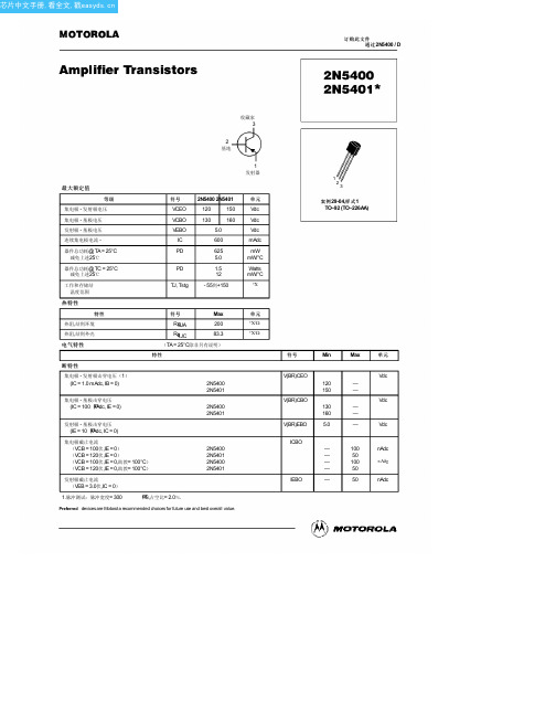
INCHES
DIM MIN MAX A 0.175 0.205 B 0.170 0.210 C 0.125 0.165 D 0.016 0.022 F 0.016 0.019 G 0.045 0.055 H 0.095 0.105 J 0.015 0.020 K 0.500 ––– L 0.250 ––– N 0.080 0.105 P ––– 0.100 R 0.115 ––– V 0.135 –––
小信号特性
电流 - 增益 - 带宽产品 (IC = 10 MADC,VCE = 10伏直流,F = 100兆赫)
输出电容
(VCB = 10 VDC,IE = 0,F = 1.0兆赫)
小信号电流增益
(IC = 1.0 MADC,VCE = 10伏直流,F = 1.0千赫)
噪声系数
(IC = 250 µAdc, VCE = 5.0伏,RS = 1.0千欧,F = 1.0千赫)
IC
600
PD
625
5.0
器件总功耗@ TC = 25°C 减免上述25℃
PD
1.5
12
工作和存储结 温度范围
TJ, Tstg - 55到+150
热特性
特性
符号
Max
热阻,结到环境 热阻,结到外壳
电气特性
RqJA
200
RqJC
83.3
(TA = 25°C除非另有说明)
特性
断特性
集电极 - 发射极击穿电压(1) (IC = 1.0 mAdc, IB = 0)
0.1
0 0.1 0.2 0.3 0.5 1.0 2.0 3.0 5.0
10 20 30 50 100
IC,集电极电流(mA)
NTE5401中文资料
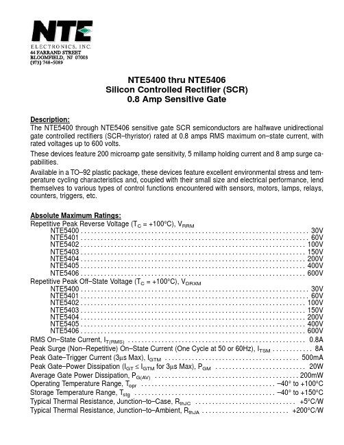
dv/dt TC = +100°C (critical)
.135 (3.45) Min
.210 (5.33) Max
Seating Plane
.500 (12.7) Min
.021 (.445) Dia Max
KG AΒιβλιοθήκη .100 (2.54) .050 (1.27)
.105 (2.67) Max .205 (5.2) Max
元器件交易网
NTE5400 thru NTE5406 Silicon Controlled Rectifier (SCR) 0.8 Amp Sensitive Gate
Description: The NTE5400 through NTE5406 sensitive gate SCR semiconductors are halfwave unidirectional gate controlled rectifiers (SCR–thyristor) rated at 0.8 amps RMS maximum on–state current, with rated voltages up to 600 volts. These devices feature 200 microamp gate sensitivity, 5 millamp holding current and 8 amp surge capabilities. Available in a TO–92 plastic package, these devices feature excellent environmental stress and temperature cycling characteristics and, coupled with their small size and electrical performance, lend themselves to various types of control functions encountered with sensors, motors, lamps, relays, counters, triggers, etc. Absolute Maximum Ratings: Repetitive Peak Reverse Voltage (TC = +100°C), VRRM NTE5400 . . . . . . . . . . . . . . . . . . . . . . . . . . . . . . . . . . . . . . . . . . . . . . . . . . . . . . . . . . . . . . . . . . . . 30V NTE5401 . . . . . . . . . . . . . . . . . . . . . . . . . . . . . . . . . . . . . . . . . . . . . . . . . . . . . . . . . . . . . . . . . . . . 60V NTE5402 . . . . . . . . . . . . . . . . . . . . . . . . . . . . . . . . . . . . . . . . . . . . . . . . . . . . . . . . . . . . . . . . . . . 100V NTE5403 . . . . . . . . . . . . . . . . . . . . . . . . . . . . . . . . . . . . . . . . . . . . . . . . . . . . . . . . . . . . . . . . . . . 150V NTE5404 . . . . . . . . . . . . . . . . . . . . . . . . . . . . . . . . . . . . . . . . . . . . . . . . . . . . . . . . . . . . . . . . . . . 200V NTE5405 . . . . . . . . . . . . . . . . . . . . . . . . . . . . . . . . . . . . . . . . . . . . . . . . . . . . . . . . . . . . . . . . . . . 400V NTE5406 . . . . . . . . . . . . . . . . . . . . . . . . . . . . . . . . . . . . . . . . . . . . . . . . . . . . . . . . . . . . . . . . . . . 600V Repetitive Peak Off–State Voltage (TC = +100°C), VDRXM NTE5400 . . . . . . . . . . . . . . . . . . . . . . . . . . . . . . . . . . . . . . . . . . . . . . . . . . . . . . . . . . . . . . . . . . . . 30V NTE5401 . . . . . . . . . . . . . . . . . . . . . . . . . . . . . . . . . . . . . . . . . . . . . . . . . . . . . . . . . . . . . . . . . . . . 60V NTE5402 . . . . . . . . . . . . . . . . . . . . . . . . . . . . . . . . . . . . . . . . . . . . . . . . . . . . . . . . . . . . . . . . . . . 100V NTE5403 . . . . . . . . . . . . . . . . . . . . . . . . . . . . . . . . . . . . . . . . . . . . . . . . . . . . . . . . . . . . . . . . . . . 150V NTE5404 . . . . . . . . . . . . . . . . . . . . . . . . . . . . . . . . . . . . . . . . . . . . . . . . . . . . . . . . . . . . . . . . . . . 200V NTE5405 . . . . . . . . . . . . . . . . . . . . . . . . . . . . . . . . . . . . . . . . . . . . . . . . . . . . . . . . . . . . . . . . . . . 400V NTE5406 . . . . . . . . . . . . . . . . . . . . . . . . . . . . . . . . . . . . . . . . . . . . . . . . . . . . . . . . . . . . . . . . . . . 600V RMS On–State Current, IT(RMS) . . . . . . . . . . . . . . . . . . . . . . . . . . . . . . . . . . . . . . . . . . . . . . . . . . . . . 0.8A Peak Surge (Non–Repetitive) On–State Current (One Cycle at 50 or 60Hz), ITSM . . . . . . . . . . . . 8A Peak Gate–Trigger Current (3µs Max), IGTM . . . . . . . . . . . . . . . . . . . . . . . . . . . . . . . . . . . . . . . . 500mA Peak Gate–Power Dissipation (IGT ≤ IGTM for 3µs Max), PGM . . . . . . . . . . . . . . . . . . . . . . . . . . . 20W Average Gate Power Dissipation, PG(AV) . . . . . . . . . . . . . . . . . . . . . . . . . . . . . . . . . . . . . . . . . . . 200mW Operating Temperature Range, Topr . . . . . . . . . . . . . . . . . . . . . . . . . . . . . . . . . . . . . . . . –40° to +100°C Storage Temperature Range, Tstg . . . . . . . . . . . . . . . . . . . . . . . . . . . . . . . . . . . . . . . . . . –40° to +150°C Typical Thermal Resistance, Junction–to–Case, RthJC . . . . . . . . . . . . . . . . . . . . . . . . . . . . . . +5°C/W Typical Thermal Resistance, Junction–to–Ambient, RthJA . . . . . . . . . . . . . . . . . . . . . . . . . . +200°C/W
TK5401中文资料
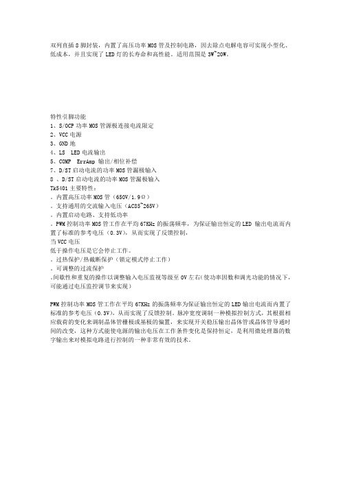
双列直插8脚封装,内置了高压功率MOS管及控制电路,因去除点电解电容可实现小型化、低成本,并且实现了LED灯的长寿命和高性能。
适用范围是3W~20W。
特性引脚功能
1、S/OCP功率MOS管源极连接电流限定
2、VCC电源
3、GND地
4、LS LED电流输出
5、COMP ErrAmp 输出/相位补偿
7、D/ST启动电流的功率MOS管漏极输入
8 、D/ST启动电流的功率MOS管漏极输入
Tk5401主要特性:。
内置高压功率MOS管(650V/1.9Ω)。
支持通用的交流输入电压(AC85~265V)。
内置启动电路、支持低功率。
PWM控制功率MOS管工作在平均67KHz的振荡频率,为保证输出恒定的LED 输出电流而内置了标准的参考电压(0.3V),从而实现了反馈控制,
当VCC电压
低于操作电压是它会停止工作。
过热保护/热截断保护(锁定模式停止工作)。
可调整的过流保护。
间歇性和重复的操作以调整输入电压监视等级至0V左右(使功率因数和调光功能的情况下,可能通过电压监控调节来实现)
PWM控制功率MOS管工作在平均67KHz的振荡频率为保证输出恒定的LED输出电流而内置了标准的参考电压(0.3V),从而实现了反馈控制。
脉冲宽度调制一种模拟控制方式,其根据相应载荷的变化来调制晶体管栅极或基极的偏置,来实现开关稳压输出晶体管或晶体管导通时间的改变,这种方式能使电源的输出电压在工作条件变化是保持恒定,是利用微处理器的数字输出来对模拟电路进行控制的一种非常有效的技术。
1n5401二极管参数代换

1n5401二极管参数代换
摘要:
1.1n5401 二极管概述
2.1n5401 二极管参数
3.1n5401 二极管参数代换方法
4.1n5401 二极管参数代换的注意事项
正文:
1.1n5401 二极管概述
1n5401 二极管是一种常见的半导体二极管,广泛应用于电子设备中,如电源、放大器、振荡器等。
它具有单向导通特性,即只能在正向电压下导通,而在反向电压下截止。
2.1n5401 二极管参数
1n5401 二极管的主要参数有:
- 正向电压(Vf):二极管导通时的正向电压。
- 反向电压(Vr):二极管截止时的反向电压。
- 正向电流(If):二极管导通时的正向电流。
- 反向电流(Ir):二极管截止时的反向电流。
3.1n5401 二极管参数代换方法
当需要用其他型号的二极管替代1n5401 二极管时,需要保证替代二极管的参数与1n5401 二极管的参数相近。
具体方法如下:
- 首先查询1n5401 二极管的参数。
- 寻找一个或多个与1n5401 二极管参数相近的二极管型号。
- 对比这些型号的参数,选择最接近1n5401 二极管参数的型号。
- 将选定的二极管型号替换1n5401 二极管,进行测试,确保替换后的电路性能稳定。
4.1n5401 二极管参数代换的注意事项
- 代换二极管时,应尽量选择同一品牌的产品,以保证参数的稳定性。
- 代换后,需要对电路进行充分测试,确保电路性能稳定,避免因参数差异导致的故障。
2N5401中文资料_数据手册_参数

IC mA
−103
1999 Apr 08
4
Philips Semiconductors
PNP high-voltage transistor
PACKAGE OUTLINE Plastic single-ended leaded (through hole) package; 3 leads
Product specification
Product specification
2N5401
DEFINITIONS
Data sheet status
Objective specification Preliminary specification Product specification
This data sheet contains target or goal specifications for product development. This data sheet contains preliminary data; supplementary data may be published later. This data sheet contains final product specifications.
−
DC current gain
IC = −1 mA; VCE = −5 V; see Fig.2
50
IC = −10 mA; VCE = −5 V; see Fig.2
60
IC = −50 mA; VCE = −5 V; see Fig.2
50
collector-emitter saturation voltage IC = −10 mA; IB = −1 mA
DESCRIPTION PNP high-voltage transistor in a TO-92; SOT54 plastic package. NPN complement: 2N5551.
山特维克 TH540 矿用自卸车 - 产品手册 - 中文说明书
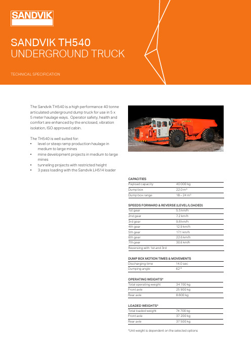
DUMP BOX MOTION TIMES & MOVEMENTS Discharging time 14.0 sec Dumping angle62 ºCAPACITIES Payload capacity 40 000 kg Dump box 22.0 m³Dump box range18 – 24 m³SPEEDS FORWARD & REVERSE (LEVEL/LOADED)1st gear 5.5 km/h 2nd gear 7.2 km/h 3rd gear 9.8 km/h 4th gear 12.9 km/h 5th gear 17.1 km/h 6th gear 22.6 km/h 7th gear30.6 km/hReversing with 1st and 3rdOPERATING WEIGHTS*Total operating weight 34 700 kg Front axle 25 900 kg Rear axle8 800 kg LOADED WEIGHTS*Total loaded weight 74 700 kg Front axle 37 200 kg Rear axle37 500 kg *Unit weight is dependent on the selected optionsThe Sandvik TH540 is a high performance 40 tonne articulated underground dump truck for use in 5 x 5 meter haulage ways. Operator safety, health and comfort are enhanced by the enclosed, vibration isolation, ISO approved cabin.The TH540 is well suited for:• level or steep ramp production haulage inmedium to large mines• mine development projects in medium to largemines• tunneling projects with restricted height•3 pass loading with the Sandvik LH514 loaderAXLESFront axleKessler D106 series spring a applied hydraulic operated brakes, equiped with standard differential, oscillation Rear axleKessler D106 series spring applied hydraulic operated brakes, equiped with standard differentialPOWER TRAINENGINE Diesel engine Volvo TAD1640VE (Tier 2)Output 405 kW (543 hp) @ 1 900 rpm Torque2 761 Nm @ 1 200 rpm Number of cylinders In-line 6Displacement 16.1 l Cooling system Liquid cooledCombustion principle Direct injected, 4-stroke, turbo with intercooler Air Filtration Dry type Electric system 24 VEmissionsTier 2, Euro Stage IIVentilation rate(Ultra low sulphur diesel)CANMET 31,400 CFM m3/s, MSHA 27,000 Ventilation Rate Particulate index(Ultra low sulphur diesel)MSHA Particulate Ventilation Index 5,000 CFM Average fuel consumption at 50 % load 40.0 l/hExhaust system Catalytic Converter Fuel tank capacity700 lTIRESTire size (Tires are application approved. Brand and type subject to availability.)29.5 R 25 E4**STANDARD OPERATOR’S COMPARTMENTCABINROPS certification according to EN ISO 3471FOPS certification according to EN ISO 3449Sealed, air conditioned, over pressurized, noise suppressed closed cabinSound absorbent material to reduce noise Laminated glass windowsCabin mounted on rubber mounts to the frame to reduce vibra-tionsAir conditioning unit located outside the cabin to reduce noise inside the cabinCyclone pre-filter for A/C deviceNo high pressure hoses in the operator’s compartment Inclinometers to indicate operating angle Emergency exitThree-point contact access system with replaceable and colour coded handles and steps Illuminated steps to the cabin12 V output for communication radio connection Remote circuit breaker switch Adjustable steering wheelREQUIREMENTS AND COMPLIANCECompliance with 2006/95/EC Low voltage directiveCompliance with 2004/108/EC Electromagnetic compatibility directiveCompliance with 2006/42/EC Machinery directive (Equipment for EU area, achieved with relevant options)Design based on EN 1889-1. Machines for underground mines. Mobile machines working underground. Safety. Part 1: Rubber tyred vehicles.Design based on MDG 15. Guideline for mobile and transportable equipment for use in mines.Electrical system based on IEC 60204-1. Safety of machinery – Electrical equipment of machines – Part 1: General requirements CONTAINS FLOURINATED GREENHOUSE GASESRefrigerant R134a under pressure max 38 bar/550 PSI:Filled weight: 2,000 kg CO2e: 2,860 tons GWP: 1430Information based on the F Gas Regulation (EU) No 517/2016OPERATOR’S SEAT Low frequency suspension Height adjustmentAdjustment according to the operator’s weight Fore-aft isolationPadded and adjustable arm rests Adjustable lumbar support Selectable dampingTwo-point seat beltOPERATIONAL CONDITIONS AND LIMITS Environmental temperature From -20 ° to +50° CStandard operating altitudeWith engine Volvo TAD1640VE from -1500 m to +1000 m at 25 °C without rated power derate Standard operating altitudeWith engine Volvo TAD1660VE from -1500 m to +1000 m at 25 °C without rated power derateCONVERTERDana C9000 series with lock-upTRANSMISSIONFully automatic transmission with electric remote shifting system and retarder. Seven gears forward and two reverse.Dana 8000 SeriesSTEERING HYDRAULICSFully hydraulic, center articulated, power steering with two double acting cylinders. Steering main valve Pilot operated Steering hydraulic cylinders 125 mm, 2 pcsSteering pump Variable displacement piston pump Emergency steeringOptionELECTRICAL EQUIPMENTMAIN COMPONENTS Alternator 28V, 150 A Batteries 2 pcs, 12V 160 Ah Starter 24 V, 7 kWDriving lights 4 pcs in front, H3 70W 2 pcs in rear, H3 70W Working light2 pcs in rear of cabin, H3 70W 2 pcs side of unit, H3 70W Reverse cameraStandard Parking, brake and indicator (blinkers) lights 2 pcs in front, LED 2 pcs in rear, LEDControl system 5,7’’ Colour display, 5 modules, inbuilt system diagnostics Lockable main switch Standard Reverse alarm (CEN)Standard Flashing beaconStandardDUMP BOX HYDRAULICSFull hydraulic system, equipped with variable displacement piston pump. Oil flows to box hydraulic system from the steering hydrau -lics. Oil flow from the brake circuit pump is divided to the brake system and oil cooler motor.Hydraulic pump Variable displacement piston pumpControl valve Solenoid operated Main valve Solenoid operated Cylinders160 mm, 2 pcsCONTROL SYSTEM, DASHBOARD AND DISPLA YS Sandvik Intelligent Control system Standard Critical warnings and alarmsDisplayed as text and with light, warnings and alarms recorded to the control system log Instrument Panel 5.7” Display with adjustable contrast and brightness Instrument PanelIlluminated switches My Sandvik Digital Services Knowledge Box™ on-board hardwareStandardFRAMEREAR AND FRONT FRAMEHigh strength structure with optimized material thicknesses. Reduced own weight for higher overall hauling capacity and long structural lifetime. Welded steel construction.Central hinge Adjustable lower bearing T anksTanks are part of frame structure Automatic central lubricationStandardHYDRAULICSFilling pump for hydraulic oilStandardDoor interlock for brakes and boxhydraulicStandardOil cooler for hydraulic and transmission oil Capability up to 55°C ambient temperature FittingsORFS Hydraulic oil tank capacity 225 l Sight glass for oil level 2 pcsBRAKESService brakes are spring applied; hydraulically operated multidisc wet brakes on all wheels. Two independent circuits: one for the front and one for the rear axle. Service brakes also function as an emer-gency and parking brake. Brake system performance complies with requirements of EN ISO 3450, AS2958.1 and SABS 1589Neutral brakeStandard Automatic brake activation system, ABAStandard Electrically driven emergency brake release pump StandardBrake pedal valve Foot operated pedal, fully modulated Brake oil tank capacity100 lDOCUMENTATION STANDARD MANUALS Operator’s Manual English and other EU languages Maintenance Manual English and other EU languages Parts ManualEnglish Service and Repair Manual EnglishT oolMan 2 x CD and 2 x USB stick in pdf format, includes all the manuals DecalsEnglish and other EU languagesINCLUDED SAFETY FEATURESFIRE SAFETYPortable fire extinguisher Standard ,12 kg (CEN)Hot side - cold side design Standard Isolation of combustibles and ignition sourcesStandardHeat isolation on exhaust manifold, turbo, and isolated exhaust pipeStandard OPTIONSSAFETY OPTIONSLower cabin height, 2716 mm, with Tier 4i engine oscillation max 9 °Cold climate packege (incl. cabin heater, cabin window defroster and side mirror with defrost system)Driving direction lights (red / green)Proximity Detection Interface Control system tool kitFire suppression system ANSUL, 2 tanks, 8 nozzles (CEN) including auto shutdown (not for automation)Fire suppression system ANSUL, 2 tanks, 8 nozzles (CEN) CHECKFIRE, including auto shutdownFire suppression system Sandvik FS1000 with auto shutdown, Eclipse foam delivered separately Safety railsEmergency steering (CEN)AutoMine TM Onboard PackageELECTRICAL OPTIONSJump start interfaceOTHER OPTIONS Cover grills for lamps Gear limitSpare rim 22.00-25/3.0 (for tyres 26.5R25)Spare rim 25.00-25/3.0 (for tyres 29.5R25)Low profile tyres 26.5R25Aggressive water package (stainless steel pipes and fittings, sealed alternator)Wiggins quick filling set for fuel and oils (hydraulic, engine and transmission)Wiggins fuel fill systemAccordance with CE-norms (CEN)AL TERNATIVE ENGINESEngine Volvo TAD1660VE, 405 kW (543 hp), Euro Stage III B (Tier 4i)Engine Volvo TAD1670VE, 405 kW (543 hp), Euro Stage IV (Tier 4f)Engine Volvo TAD1670VE, 405 kW (543 hp), MSHA, Canmet (US & Canada only) (Tier 4f)ENERGY ISOLATIONLockable main switch, ground level accessStandardEmergency stop push buttons according to EN ISO 13850Standard 1 pc in cabin1 pc in front frame2 pcs in rear frame Pressure release in the radiator capStandard Automatic discharge for pressure accumulators (brake system and pilot circuit)Standard Frame articulation locking device Standard Mechanical dump box locking device StandardWheel chocks and bracketsStandardGRADE PERFORMANCEVolvo TAD1640VE Tier 2 and TAD1660 Tier 4iCalculated with 2% rolling resistanceWith lock-upEmptyPercent grade051015201st gear (km/h) 5.5 5.4 5.4 5.4 5.4 2nd gear (km(h)7.27.27.17.17.0 3rd gear (km/h)9.89.79.79.69.5 4th gear (km/h)13.012.812.712.512.4 5th gear (km/h)17.216.916.616.414.4 6th gear (km/h)22.822.321.819.47th gear (km/h)31.130.126.1LoadedPercent grade051015201st gear (km/h) 5.5 5.4 5.3 5.3 5.2 2nd gear (km(h)7.27.17.0 6.9 6.6 3rd gear (km/h)9.89.69.48.8 5.0 4th gear (km/h)12.912.611.89.25th gear (km/h)17.116.512.46th gear (km/h)22.620.37th gear (km/h)30.6StandardDump box alternatives (m³)18 m³20 m³22 m³24 m³L1 (mm)10700107001070010700 L2 (mm)3698369836983698 L3 (mm)1807180718071807 L4 (mm)3585358535853585 L5 (mm)1610161016101610 H1 (mm)2906290629062906 H2 (mm)5977606261236146 H3 (mm)2586273128862946 H4 (mm) 505505505505 H5 (mm)457457457457 H6 (mm)890890890890 H7 (mm)655657656656 W1 (mm)3000305030003150 W2 (mm)2614261426142764 W3 (mm)2986298629862986 W4, axle (mm)3065306530653065 A113.5°13.5°13.5°13.5°A262°62°62°62°A342.5°42.5°42.5°42.5°R1 (mm)5055505550555010 R2 (mm)9120912091209120 T (mm)55465546554655783-T H 540-25/E N G /M E T R I C © S a n d v i k M i n i n g a n d R o c k T e h c n o l o g y 2017 S A N D V I K i s a r e g i s t e r e d t r a d e m a r k o w n e d b y S a n d v i k I n t e l l e c t u a l P r o p e r t y A B i n S w e d e n a n d o t h e r c o u n t r i e s .Sandvik Mining and Rock Technology reserves the right to make changes to the information on this data sheet without prior notification to users. Please contact a Sandvik representative for clarification on specifications and options.。
数控车刀型号说明之欧阳术创编

外圆车刀型号说明内孔车刀型号说明可转位精密车刀简介可转位精密车刀是车削工具系统中主要部件,规格、品种较多的产品之一,精密级产品,车刀的主要尺寸公差控制在±0.08mm以内。
螺钉夹紧式外圆车刀螺钉夹紧式外圆车刀SDJCR/L、SDPCN、SDPCR/L、SSDPN、STACR/L、SCGCR/L、SCFCR/L、SCLCR/L、SRDCN、SRGCR/L、SVJBR/L、SVVBN、SVHBR/L0808H09STACR/L10 10 10 101010H09STACR/L12 12 12 121212H09STAPR/L16 16 16 16 131616H11STAPR/LTCMT11020420 20 20 25 18 1252020K11STAPR/L25 25 25 32 25 1502525M11型号b h h1f l2l1刀尖半径配用刀片螺钉扳手0.4 CCMT060204 M2.5x5 T8 SCGCR/L 1212H0612 12 12 16 12100SCGCR/L 1616H0916 16 16 20 16SCGCR/L 2020K0920 20 20 25 25 1250.8 CCMT09T308 M4x9 T15 SCGCR/L 2525M0925 25 25 32 25 150螺钉夹紧式外圆车刀刀尖半型号b h h1f l2l1配用刀片螺钉扳手径SCFCR/L0.4 CCMT0602 M2.5x5 T812 12 12 161212H0616 100SCFCR/L16 16 16 201616H09SCFCR/L0.8 CCMT09T308 M4x9 T1520 20 20 25 25 1252020K09SCFCR/L25 25 25 32 25 1502525M09刀尖半型号b h h1f l2l1配用刀片螺钉扳手径SCLCR/L0.4 CCMT060204 M2.5x5 T812 12 12 16 121212H06100SCLCR/L16 16 16 20 161616H090.8 CCMT09T308 M4x9 T15 SCLCR/L20 20 20 25 25 1252020K09螺钉夹紧式外圆车刀螺钉夹紧式内孔车刀螺钉夹紧式内孔车刀S-STFPR/L、S-STUPR/L、S-STLPR/L、S-SSKPR/L、S-SCLCR/L、S-SDUCR/LSCLCR/L0932 25 17 250 40 23 22.5 6°型号最小加工直径Dd f l1l2H Bα°a刀尖半径配用刀片螺钉扳手S12M-SDUCR/L0716 12 9 150 25 11 11.5 8°7.0 0.4 DCMT070204 M2.5x5 T8 S16Q-SDUCR/L0720 16 11 180 30 14 15 6°S20R-SDUCR/L1125 20 13 200 35 18 18.5 8° 10.5 0.8 DCMT11T308 M4x9 T15复合上压式车刀型号b h.h1l1f l2a刀尖半径配用刀片复合上压式车刀型号 b h.h1 l1 f l2 a 配用刀片MSSNR/L20 20 125 252020K1234 8 SNMG120408 MSSNR/L25 25 150 322525M12MSSNR/L25 32 170 32 38 10 SNMG150612 3225P15型号f h1l2b h l1A配用刀片MRGNR/L25 2020 20 1252020K1228MRGNR/L?12 RNMG120432 25 25 25 1502525M12MRGNR/L32 32 32 25 32 1703225P12刀尖半型号f h1l2b h l1a配用刀片径MDPNN 10 20 45 20 20 125 12 0.8 DNMG150608复合上压式车刀MSBNR/L、MSDNN、MSKNR/L、MSSNR/L、MRGNR/L、MDPNN、MTGNR/L、MCLNR/L、MTFNR/L、MWLNR/L、MDJNR/L、MDHNR/L复合上压式车刀杠杆式车刀PSBNR/L、PSDNN、PSSNR/L、PCFNR/L、PSKNR/L、PCBNR/L、PTGNR/L、PCLNR/L、PTFNR/L、PDPNN、PDJNR/L、PDHNR/L、PRGNR/LPSSNR/L3225P1232 32 170 161.71.2SNMG150608 PSSNR/L4040R1950 32.5 40 40 40 40 200 187.5 12 SNMG190612杠杆式车刀型号f f1h1l2b h l1a刀尖半径配用刀片PCFNR/L2020K122518202820 20 12512 0.8 CNMG120408PCFNR/L2525M1232252525 150PCFNR/L3225P1232 32 170型号f f1h1l2b h l1l0a刀尖半径配用刀片PSKNR/L1616H0920 15 16 17 16 16 100 102 80.8SNMG090308 PSKNR/L 25 17 20 22 20 20 125 128 11 SNMG120408PSKNR/L2525M1232 25 25 25 150 153PSKNR/L3232P1540 22 32 30 32 32 170 174 13.51.2SNMG150612 PSKNR/L4040R1950 27 40 40 40 40 200 205 16.5 SNMG190612型号f h1l2b h l1a刀尖半径配用刀片PCBNR/L2020K1217 2028 20 20 12511 0.8 CNMG120408PCBNR/L2525M1222 252525 150PCBNR/L3225P1632 31 32 170 14.5 1.2 CNMG160612杠杆式车刀型号f f1h1l2b h l1a刀尖半径配用刀片PTGNR/L 20 16 16 22 16 16 100 14.5 0.8 TNMG160408杠杆式车刀切断(槽)刀型号说明QZQ1616RL、QZQ2020RL、QZQ2525RL、QZQ3225RL切断(槽)刀螺纹车刀型号说明外螺纹车刀型号hh1bLf配用刀片螺 钉 扳 手SE R/L 1616H16 16 16 16 100 20 16ER/L M3.5x14 T15SE R/L 2020K16 20 20 20 125 25SE R/L 2525M16 25 25 25 15032SE R/L 3225P16 32 32 25 170 SE R/L 3232P16 32 32 32 170 40 SE R/L 2525M22 25 25 25 150 32 22ER/L M4x15T20SE R/L 3225P22 32 32 25 170 32 SE R/L 3232P2232323217040内螺纹车刀SER/L,SNR/L。
TK5401(中文)

目录
一、升级历史...................................................................................................................................1 二、基本描述...................................................................................................................................1 三、特性...........................................................................................................................................1 四、结构图.......................................................................................................................................2 五、管脚说明...................................................................................................................................2 六、封装外形...................................................................................................................................3 七、电气特性...................................................................................................................................3
1n5401二极管整流参数
1N5401二极管整流参数1. 引言二极管是一种最常见的电子元件,具有只允许电流沿一个方向流动的特性。
1N5401是一种常用的高功率整流二极管,常用于电源电路中的整流器。
本文将详细介绍1N5401二极管的主要参数和特性。
2. 1N5401二极管概述1N5401是一种高功率硅整流二极管,其外观为黑色塑料封装。
它由PN结组成,其结构使得电流只能从P端流向N端,阻止了反向电流的流动。
3. 主要参数3.1 最大重复逆向电压(Maximum Repetitive Reverse Voltage,VRRM)最大重复逆向电压指的是在正向电压为零时,二极管可承受的最大逆向电压。
对于1N5401,其最大重复逆向电压为1000V。
3.2 最大平均整流电流(Maximum Average Rectified Current,IO)最大平均整流电流是指在特定条件下,二极管能够持续承受的最大整流电流。
对于1N5401,其最大平均整流电流为3A。
3.3 最大峰值反向电压(Maximum Peak Reverse Voltage,VR)最大峰值反向电压指的是二极管可承受的最大反向电压。
对于1N5401,其最大峰值反向电压为1200V。
3.4 最大峰值反向电流(Maximum Peak Reverse Current,IR)最大峰值反向电流是指在特定条件下,二极管能够承受的最大反向电流。
对于1N5401,其最大峰值反向电流为200mA。
3.5 正向电压降(Forward Voltage Drop,VF)正向电压降指的是电流通过二极管时产生的电压降。
对于1N5401,其正向电压降一般为0.9V至1.3V。
3.6 反向恢复时间(Reverse Recovery Time,Trr)反向恢复时间指的是二极管在切换从正向电流到反向电流时所需的时间。
对于1N5401,其反向恢复时间为500ns。
4. 特性4.1 高逆向电压承受能力1N5401具有较高的最大重复逆向电压和最大峰值反向电压,能够应对高反向电压的需求。
- 1、下载文档前请自行甄别文档内容的完整性,平台不提供额外的编辑、内容补充、找答案等附加服务。
- 2、"仅部分预览"的文档,不可在线预览部分如存在完整性等问题,可反馈申请退款(可完整预览的文档不适用该条件!)。
- 3、如文档侵犯您的权益,请联系客服反馈,我们会尽快为您处理(人工客服工作时间:9:00-18:30)。
KST5401PNP Epitaxial Silicon TransistorAbsolute Maximum Ratings T a =25°C unless otherwise notedElectrical Characteristics T a =25°C unless otherwise notedSymbol ParameterValue Units V CBO Collector-Base Voltage -160V V CEO Collector-Emitter Voltage -150V V EBO Emitter-Base Voltage -5V I C Collector Current-500mA P C Collector Power Dissipation 350mW T STGStorage Temperature150°CSymbol ParameterTest ConditionMin.Max.Units BV CBO Collector-Base Breakdown Voltage I C = -100µA, I E =0-160V BV CEO Collector-Emitter Breakdown Voltage I C = -1.0mA, I B =0-150V BV EBO Emitter-Base Breakdown Voltage I E = -10µA, I C =0-5V I CBO Collector Cut-off Current V CB = -100V, I E =0 -50nAh FEDC Current GainV CE = -5V, I C = -1.0mA V CE = -5V, I C = -10mA V CE = -5V, I C = -50mA 506050240V CE (sat)Collector-Emitter Saturation Voltage I C = -10mA, I B = -1.0mA I C = -50mA, I B = -5mA -0.2-0.5V V V BE (sat)Base-Emitter Saturation Voltage I C = -10mA, I B = -1.0mA I C = -50mA, I B = -5mA -1.0-1.0V V f T Current Gain Bandwidth Product I C = -10mA, V CE = -10V f=100MHz100300MHz C ob Output Capacitance V CB = -10V, I E =0, f=1.0MHz 6.0pF NFNoise FigureV CE = -5V, I C = -200µAR S =10K Ω, f=10Hz to 15.7KHz 8.0dBKST5401High Voltage Transistor2LMarking1. Base2. Emitter3. CollectorSOT-23123KST5401KST5401TRADEMARKSThe following are registered and unregistered trademarks Fairchild Semiconductor owns or is authorized to use and is not intended to be an exhaustive list of all such trademarks.DISCLAIMERFAIRCHILD SEMICONDUCTOR RESERVES THE RIGHT TO MAKE CHANGES WITHOUT FURTHER NOTICE TO ANY PRODUCTS HEREIN TO IMPROVE RELIABILITY, FUNCTION OR DESIGN. FAIRCHILD DOES NOT ASSUME ANY LIABILITY ARISING OUT OF THE APPLICATION OR USE OF ANY PRODUCT OR CIRCUIT DESCRIBED HEREIN;NEITHER DOES IT CONVEY ANY LICENSE UNDER ITS PATENT RIGHTS, NOR THE RIGHTS OF OTHERS.LIFE SUPPORT POLICYFAIRCHILD’S PRODUCTS ARE NOT AUTHORIZED FOR USE AS CRITICAL COMPONENTS IN LIFE SUPPORT DEVICES OR SYSTEMS WITHOUT THE EXPRESS WRITTEN APPROVAL OF FAIRCHILD SEMICONDUCTOR CORPORATION.As used herein:1. Life support devices or systems are devices or systems which, (a) are intended for surgical implant into the body,or (b) support or sustain life, or (c) whose failure to perform when properly used in accordance with instructions for use provided in the labeling, can be reasonably expected to result in significant injury to the user.2. A critical component is any component of a life support device or system whose failure to perform can be reasonably expected to cause the failure of the life support device or system, or to affect its safety or effectiveness.PRODUCT STATUS DEFINITIONS Definition of TermsDatasheet Identification Product Status DefinitionAdvance InformationFormative or In Design This datasheet contains the design specifications for product development. Specifications may change in any manner without notice.PreliminaryFirst ProductionThis datasheet contains preliminary data, andsupplementary data will be published at a later date.Fairchild Semiconductor reserves the right to make changes at any time without notice in order to improve design.No Identification Needed Full ProductionThis datasheet contains final specifications. Fairchild Semiconductor reserves the right to make changes at any time without notice in order to improve design.Obsolete Not In ProductionThis datasheet contains specifications on a product that has been discontinued by Fairchild semiconductor.The datasheet is printed for reference information only.FACT™FACT Quiet series™FAST ®FASTr™FRFET™GlobalOptoisolator™GTO™HiSeC™I 2C™ImpliedDisconnect™ISOPLANAR™LittleFET™MicroFET™MicroPak™MICROWIRE™MSX™MSXPro™OCX™OCXPro™OPTOLOGIC ®OPTOPLANAR™PACMAN™POP™Power247™PowerTrench ®QFET™QS™QT Optoelectronics™Quiet Series™RapidConfigure™RapidConnect™SILENT SWITCHER ®SMART START™SPM™Stealth™SuperSOT™-3SuperSOT™-6SuperSOT™-8SyncFET™TinyLogic™TruTranslation™UHC™UltraFET ®VCX™ACEx™ActiveArray™Bottomless™CoolFET™CROSSVOLT ™DOME™EcoSPARK™E 2CMOS™EnSigna™Across the board. Around the world.™The Power Franchise™Programmable Active Droop™。
