JE935HTR1中文资料
HTR系列高压热变电阻软起动装置(简称热变电阻)用于大中
HTR系列高压热变电阻软起动装置一、概述HTR系列高压热变电阻软起动装置(简称热变电阻)用于大中型高压鼠笼交流异步电动机或异步起动的高压同步电动机,作电阻降压起动之用。
使用该装置起动的电机具有起动电流小且恒定、转矩逐步增加的软起动特性,起动过程中无电流冲击和机械冲击,起动时对电网影响小,无电磁干扰、是起动电抗器和自耦降压起动器的理想替代产品, 相对于大容量高压变频软起动而言,又具有明显的操作简单、免维护、无谐波污染等优势。
高压热变电阻软起动装置广泛用于电压等级3kV、6kV、10kV,功率范围250kW~45000kW甚至更大容量电机的降压软起动。
该装置采用五项专利技术,技术水平国内领先。
专利号:ZL 97 2 41662.X ZL 99 2 45458.X ZL 03254078.X ZL 02290367.X ZL 03254077.X。
二、正常工作条件环境温度:上限50℃(24小时平均气温不超过45℃),下限-5℃;相对湿度不超过85%;海拨高度不超过1000M;应放置室内无剧烈振动及冲击且垂直倾斜度不超过5°的场合;安装场所不允许有导电尘埃及腐蚀性气体;没有火灾及爆炸危险。
注:海拨高度超过1000m的地区,用户订货时应予说明。
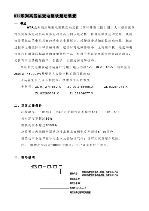
三、型号说明四、产品特点4.1 工作原理高压热变电阻软起动装置由具有负温度特性的三相平衡电阻组成。
当该电阻通入电流时,电阻体温度逐步升高而电阻值逐步减小,从而使电机端电压逐步升高,起动转矩逐步增加,以实现电机平稳起动且降低起动电流的目的。
该装置可与高压软起动控制柜、隔离柜、切换柜、星点控制柜组成,成套供应,接入电机起动回路,具有起动电动机和完成电机起动过程中的保护的功能。
4.2 性能特点根据产品性能及不同配置,我们将高压热变电阻软起动装置分为HTR3、HTR4、HTR6三大系列,以满足不同用户的需要。
具体性能特点见表一,也可根据用户要求作相应调整。
HTR3、HTR4、HTR6系列均具有以下基本性能特点:1)恒电流,软起动:起动电流为电机额定运行电流的2.0~3.5倍,降低了电机起动发热,有效地延长电机使用寿命;2)确保一次起动成功,不受电网电压波动和负载变动的影响;3)起动平稳,对机械设备无冲击;4)对电网影响小,起动时电网压降小;5)起动时功率因数高;6)无谐波污染;7)静态变阻起动,安全可靠;8)操作简单,免维护。
9395产品简介与技术参数

Eaton PW9395UPS产品介绍与技术参数1.1 Eaton PW9395UPS概述Powerware9395系列UPS产品是伊顿公司推出的第五代大功率UPS电源,单机容量从200KV A至1100KVA。
它由伊顿位于美国和芬兰的工厂联合研发,是美国军方指定的UPS产品。
9395系列采用当今最先进的电力电子技术,充分考虑新时代用户负载的实际使用环境和使用特点,并且集其在电源系统设计方面40余年的先进技术与丰富经验,全力打造出的一款为最关键负载提供高可靠供电保护的、具有创造性的不间断电源系统。
可以全面满足大型数据中心、通讯中心、机房、工厂自动化、大型医疗系统或大型办公等应用场所的电力保障要求。
随着集成电路、各种高精密设备和仪器的广泛应用,用户对于电源产品的质量与品质也提出了更高的要求,UPS不但要解决停电影响,还要能消除各种高频杂波、突波、电压下陷、瞬间断电等电力干扰对信息设备的危害,以确保信息网络的安全稳定运行。
伊顿在充分结合自身优势和广泛听取用户的意见后,在保证产品优秀品质的同时融入更多更具人性化的设计。
1.2 Eaton PW9395UPS系统描述这种UPS是一个即时双向转换UPS,它可为计算机系统和其他的诸如测量设备、工业自动控制设备等智能设备提供电源保护,为关键设备提供连续的经过过滤的三相电源。
在给设备提供电源的同时,UPS也在持续的给电池充电,如果突然发生停电事故,UPS可继续不间断的从UPS的输入端为设备提供电源。
如果停电的时间超过了储备电量所能支持的时间,UPS会自动的关闭以免电池完全放电。
来电的时候UPS会自动启动继续为关键设备提供电源并且给电池组充电。
1.3 Eaton PW9395UPS特点详述✓全IGBT设计,输入功率因数>0.99,输入THDI<3%✓全球最高的整机效率,即使在半载时依然可达95%✓ABM智能化电池管理系统,延长电池使用寿命50%✓32位DSP数字控制技术✓整流器和逆变器的一体化、通用化、模块化设计✓Hot-Sync热同步并机专利技术,模块化冗余并联设计✓风道式冷却系统,冗余风扇,风扇转速检测技术✓冗余逻辑电源设计✓Easy-Load负载测试专利技术✓简洁方便的可操作维护性✓强大的监控通讯能力✓ESS节能模式与休眠模式1.3.1全IGBT技术9395系列UPS采用了全IGBT结构,即UPS的整流器和逆变器均采用IGBT作为功率开关元件。
江特9PX3000IRTM生革上海艇电源数据册说明书

Eaton 9PX3000IRTMEaton 9PX Marine UPS, 3000 VA, 3000 W, Input: C20, Outputs: (8)C13, (2) C19, Rack/tower, 3UGeneral specificationsEaton 9PX marine UPS9PX3000IRTM48.5 cm13 cm44 cm27.41 kg3 year on electronics, 2 year on battery CE MarkedFCC part 15 Class BTUVCISPR22 Class BCSA 22.2cULus ListedENERGY STAR certified DNV GL CertifiedEACIEC/EN 62040-1UL 1778IEC/EN 62040-2CE Eaton 9PX 3000i RT3U MarineProduct Name Catalog Number Product Length/Depth Product Height Product Width Product Weight Warranty CompliancesCertifications Model CodeSealed, lead-acidView runtime graphHot-swappable internal batteries and extended battery modules (EBMs)12 V / 9 AhYes (8) C13, (2) C19230V3000 W1200/208/220/230/240 V +/- 1%Sine wave230V default (200/208/220/230/240V) 31Online/Double-conversion3000 VAC20230V default (200/208/220/230/240V) 50/60 Hz>.991.8m NoBattery typeRuntime graphBattery replacement Battery ratingExtended battery capability ReceptacleVoltageWattageOutput power factorOutput voltage rangeOutput waveformOutput nominal voltageVoltage distortion output (linear load) - max Feed typeTopologyVA ratingInput connection Input nominal voltage Nominal frequency Input power factor Input cord length Includes network cardCommunicationUSB port (HID compliant) Serial port (RS232)Mini terminal block for remote On/OffMini-terminal block for remote power offMini-terminal block for output relayDry contacts (3 outputs, 1176-276 V (100-276 V with derating)40-70 HzNoMultilingual graphical LCD display YesOne slot for optional communication card Eaton Intelligent Power Manager, Eaton Intelligent Power Protector Other3000 m <40 dB at 1 meter 0° to 40°C (32° to 104°F)0-96% non-condensing482.6 mm (19 inch) device 1YesYes Input voltage rangeInput frequency range Ethernet interfaceUser interfacePotential free switch contact Expansion slotsSoftware compatibilityType of interface Altitude Noise level Temperature range Relative humidity Construction typePackage contents Phase (output)Internal bypass Auto shutdown function Colorinput, optocoupler, DB9)UPS Input cable(2) IEC-IEC output cables USB cable Serial cable(2) brackets for 19’ mounting (2) Rack-mounting kit (2) Supports for tower mountingCable locking system Safety instructions Quickstart guideEaton Corporation plc Eaton House30 Pembroke Road Dublin 4, Ireland © 2023 Eaton Toate drepturile rezervate.Eaton is a registered trademark.All other trademarks are property of their respective owners./socialmediaBlack/silver94Yes1NoEaton Specification Sheet - 9PX3000IRTMEfficiency Rack mounting kit Phase (input)Hot swap power Specifications and datasheets。
JUMO 紧固定电导性温度传感器系列说明书

Page 1/4Fax:+49 661 6003-607e-mail:Internet: Fax:+44 1279 635262e-mail:Internet: Fax:315-697-5867e-mail:Internet:Screw-in RTD temperature probewith terminal head form J■For temperatures from -50 to +400°C■As single or double RTD temperature probes ■Available with transmitter ■Protection class IP65Screw-in RTD temperature probes are preferentially used for measuring temperatures in liquids and gases. A decisive selection criterion is the reliable sealing feature of this installation type with vacuum and with overpressure. The application areas are, among others, in the air conditioning technology and refrigeration engineering as well as the HVAC, kiln and apparatus engineering sector.The measuring insert is normally fitted with a Pt100 temperature sensor according to DIN EN 60751, Class B in 2-wire circuit; versions with Pt500 or Pt1000 temperature sensors can also be supplied, as well as 3- and 4-wire circuit connections. A transmitter can be optionally integrated into the connection head.Technical DataTerminal headForm J, die-cast aluminum, M 16x1.5; IP65, ambient temperature -40 to +100°C Caution: reduced ambient temperature range when using transmitters,Data Sheet 70.7030Process connection thread, stainless steel 1.4571Protection tube Stainless steel 1.4571, Ø6mm and Ø8mmMeasuring insert Pt100 temperature sensor according to DIN EN 60751, Class B, two-wire circuit Response times t 0.5 = 5 sec, t 0.9 = 14 sec, in water 0.4m/sec, 6mm dia.Transmitter Analog transmitter, output 4 to 20mA, Data sheet 70.7030AccessoriesSheath, Data Sheet 90.9710 (90.9721)Page 2/4Fax:+49 661 6003-607e-mail:*************Internet: Fax:+44 1279 635262e-mail:*************.uk Internet: Fax:315-697-5867e-mail:************Internet:DimensionsType 902030/10Type 902030/11Type 902030/31Type 902030/80Page 3/4Fax:+49 661 6003-607e-mail:*************Internet: Fax:+44 1279 635262e-mail:*************.uk Internet: Fax:315-697-5867e-mail:************Internet:Order details:Screw-in RTD temperature probe with terminal head form J(1)Basic type902030/10Screw-in RTD temperature probes with continuous sheath902030/11Screw-in RTD temperature probes with stepped sheath(with Ø6 to Ø3.8mm; with Ø8 to Ø6mm)902030/31Screw-in RTD temperature probes with stepped sheath for air measurement902030/80Screw-in RTD temperature probes with spring-loaded connection,12mm spring deflection,connection head rotatable by 360°(2)Operating temperature in °Cx x647-20 to +150°C (only in conjunction with class B and 1x Pt100/1x Pt1000 in 2-wire circuit)x378-50 to +180°C x x x380-50 to +200°C x x 386-50 to +260°C x x 402-50 to +400°C (3)Measuring insertx x x x 10011x Pt100 in 3-wire-circuit x x x x 10031x Pt100 in 2-wire circuit x x x x 10051x Pt1000 in 2-wire circuit x x x x 10111x Pt100 in 4-wire circuit x x x x20032x Pt100 in 2-wire circuit(4)Tolerance class according to EN 60751x x x x 1Class B (standard)x x x x 2Class A(5)Protection tube diameter D in mm x x x 6Ø6mm (standard)x x 8Ø8mm (6)Fitting length EL in mm (100≤EL ≤1000)x x 5050mm x x x x 100100mm x x x x 150150mm x x x x 250250mm x x x x 300300mmxx xx...Specification in plain text (50mm steps)(7)Process connection x x x 102Screw connection (thread) G 1/4x x x 103Screw connection (thread) G 3/8x x x x 104Screw connection (thread) G 1/2(8)Extra codesx x x x 000without extra codesx x x x3301x analog transmitter, 4 to 20mA 1 output, Data sheet 70.7030(1)(2)(3)(4)(5)(6)(7)(8)Order code ------/Order example902030/10-402-1001-1-6-100-104/0001Specify measuring range in plain text.Page 4/4Fax:+49 661 6003-607e-mail:*************Internet: Fax:+44 1279 635262e-mail:*************.uk Internet: Fax:315-697-5867e-mail:************Internet:Stock versions(1)(2)(3)(4)(5)(6)(7)(8)Part No.902030/10-380-2003-1-6-50-104/00090/00533450902030/10-380-2003-1-6-100-104/00090/00533451902030/10-380-2003-1-6-150-104/00090/00533452902030/10-402-1003-1-6-50-104/00090/00055692902030/10-402-1003-1-6-100-104/00090/00055693902030/10-402-1003-1-6-150-104/00090/00055694902030/10-402-1003-1-6-300-104/00090/00065691902030/10-402-1003-1-6-250-104/00090/00533433902030/10-402-2003-1-6-50-104/00090/00383011902030/10-402-2003-1-6-100-104/00090/00526429902030/10-402-2003-1-6-150-104/00090/00533442902030/10-402-1003-1-6-50-103/00090/00478984902030/10-402-1003-1-6-100-103/00090/00424045902030/10-380-1003-1-6-100-104/330(-40 to +60°C)90/00533453902030/10-647-1003-1-6-100-104/330(0 to 100°C)90/00533454902030/10-647-1003-1-6-150-104/330(0 to 100°C)90/00533468902030/10-402-1005-1-6-100-104/00090/00359611902030/10-402-1005-1-6-150-104/00090/00411610902030/10-647-1003-1-6-50-104/00090/00533448902030/10-647-1003-1-6-100-104/00090/00533449902030/10-647-1003-1-6-150-104/00090/00508957902030/31-380-1003-1-6-75-104/00090/00438406902030/31-380-1003-1-6-100-104/00090/00438408902030/31-380-1003-1-6-150-104/00090/00438409。
里氏硬度计说明书

里氏硬度计说明书篇一:TH110A里氏硬度计使用说明书TH110A里氏硬度计使用说明书1 概述 ................................................ ................................................... . (3)1.1 产品特点 ................................................ ................................................... .. 31.2 主要用途及适用范围 ................................................ (3)1.2.1主要用途................................................. (3)1.2.2适用范围................................................. ...................................................31.3 品种规格 ................................................ ................................................... .. 41.4 工作条件 ................................................ ................................................... .. 41.5 注意事项 ................................................ ................................................... .. 42 结构特征与工作原理................................................. (5)2.1结构特征 ................................................ ................................................... (5)2.1.1硬度计 ................................................ (5)2.1.2 主机 ................................................ ................................................... . (5)2.1.3 D型冲击装置 ................................................ (6)2.1.4 异型冲击装置 ................................................ .. (6)2.2工作原理 ................................................ ................................................... (6)3 技术特性 ................................................ ................................................... (7)4 仪器使用 ................................................ (8)4.1 使用前的准备和检查 ................................................ (8)4.1.1被测试样的要求 ................................................ .. (8)4.1.2仪器系统设置................................................. .. (8)4.1.3测量条件设置................................................. .. (8)4.2 测量方法 ................................................ ................................................... .. 94.2.1启动................................................. ................................................... . (9)4.2.2加载................................................. ................................................... . (9)4.2.3 定位 ................................................ ................................................... . (9)4.2.4测量................................................. ................................................... . (9)4.2.5读取测量值 ................................................ . (10)4.2.6关机................................................. ................................................... .. (10)5特别提示 ................................................ ................................................... (10)6仪器操作详解 ................................................ ................................................... .. (11)6.1开机 ................................................ ................................................... (11)6.2关机 ................................................ ................................................... (11)6.3测量 ................................................ ................................................... (11)6.3.1主显示界面说明 ................................................ . (11)6.3.2测量操作................................................. (12)6.3.3按键操作................................................. . (12)6.4 菜单结构图 ................................................ (13)6.5 测量条件设置 ................................................ .. (13)6.5.1冲击方向设置................................................. (14)6.5.2平均次数设置................................................. (14)6.5.3材料设置................................................. . (14)6.5.4硬度制设置 ................................................ . (15)6.5.5公差限设置 ................................................ . (15)6.5.6硬度/强度设置 ................................................ (15)6.6 打印功能 ................................................ ...................................................166.6.1 打印当前数值 ................................................ (16)6.6.2 打印存储数值 ................................................ (16)6.6.3 打印全部存储值 ................................................ .. (17)6.6.4 走纸(手动进纸) .............................................. . (17)6.7. 存储管理................................................. ..................................................176.7.1从第一组浏览/从最末组浏览 ................................................ (17)6.7.2从所选组浏览................................................. (17)6.7.3传输数据................................................. . (17)6.7.4删除所选组 ................................................ . (18)6.7.5全部删除................................................. . (18)6.7.6确认删除................................................. . (18)6.8数据浏览 ................................................ ....................................................186.9 系统设置 ................................................ ...................................................196.9.1液晶亮度设置................................................. (20)6.9.2时间日期设置................................................. (20)6.10 软件信息................................................. . (20)6.11 软件校准 ................................................ ..................................................216.12 背光................................................. ................................................... .. (21)6.13 自动关机................................................. . (21)6.14 打印纸卷安装................................................. (22)6.15 电池充电................................................. . (22)6.16 电池更换................................................. . (22)6.17数据传输电缆连接................................................. (23)7 故障分析与排除................................................. ..................................................238保养和维修 ................................................ ................................................... . (23)8.1冲击装置维护 ................................................ (23)8.2仪器维修程序 ................................................ (23)9仪器检定 ...................................... ................................................... (23)10 贮存条件、运输及注意事项 ................................................ . (23)附录................................................. ................................................... .. (24)附表1 .................................................................................................... . (24)附表2 ................................................. ................................................... . (25)附表3 ................................................. ................................................... . (26)附表4 ................................................. ................................................... . (27)用户须知 ................................................ ................................................... .. (28)1 概述1.1 产品特点? 依据里氏测量原理,可以对多种金属材料进行检测。
Turck NI4-DSU35TC-2Y1X2 S933 感应传感器-用于旋转执行器 手册说明书
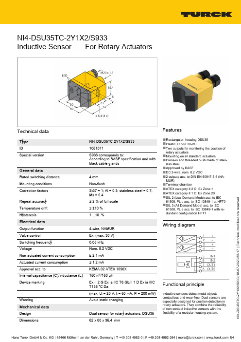
U 35T C -2Y 1X 2/S 933 | 18-07-2023 22-17 | T e c h n i c a l m o d i f i c a t i o n s r e s e r v e dNI4-DSU35TC-2Y1X2/S933Inductive Sensor – For Rotary ActuatorsTechnical dataNI4-DSU35TC-2Y1X2/S9331051011S933 corresponds to:According to BASF specification and with black cable glands Rated switching distance 4 mm Non-flushSt37 = 1; Al = 0.3; stainless steel = 0.7;Ms = 0.4≤ 2 % of full scale ≤ ±10 %1…10 %4-wire, NAMUR Exi (max. 30 V)0.05 kHz Nom. 8.2 VDC Non-actuated current consumption ≥ 2.1 mA Actuated current consumption ≤ 1.2 mAKEMA 02 ATEX 1090X Internal capacitance (C i )/inductance (L i )150 nF/150 µHEx II 2 G Ex ia IIC T6 Gb/II 1 D Ex ia IIIC T135 °C Da(max. U i = 20 V, I i = 60 mA, P Avoid static chargingFeatures■Rectangular, housing DSU35■Plastic, PP-GF30-VO■Two outputs for monitoring the position of rotary actuators■Mounting on all standard actuators■Press-in and threaded bush made of stain-less steel■Approved by BASF■DC 2-wire, nom. 8.2 VDC■2 outputs acc. to DIN EN 60947-5-6 (NA-MUR)■Terminal chamber■ATEX category II 2 G, Ex Zone 1■ATEX category II 1 D, Ex Zone 20■SIL 2 (Low Demand Mode) acc. to IEC 61508, PL c acc. to ISO 13849-1 at HFT0■SIL 3 (All Demand Mode) acc. to IEC61508, PL e acc. to ISO 13849-1 with re-dundant configuration HFT1Wiring diagramFunctional principleInductive sensors detect metal objectscontactless and wear-free. Dual sensors are especially designed for position detection in rotary actuators. They combine the reliability of non-contact inductive sensors with theU 35T C -2Y 1X 2/S 933 | 18-07-2023 22-17 | T e c h n i c a l m o d i f i c a t i o n s r e s e r v e dTechnical dataAccessoriesBTS-DSU35-EB16900225Actuation kit (puck) for dual sensors;end position damped; hole pattern on receptacle surface: 80 x 30 mm and 130 x 30 mm; connection shaft (shaft extension) height: 20 mm (30 mm)/Ø:max. 30 mmBTS-DSU35-Z016900229Mounting kit for dual sensors forlarger rotary actuators; Ø spacer plate and snap ring: max. 65 mm; hole pattern on receptacle surface: 30 x 80 mm (30 x 130 mm); connection shaft (shaft extension) height: 20 mm/Ø: max. 30 mmBTS-DSU35-Z026900230Mounting kit for dual sensors forlarger rotary actuators; Ø spacer plate and snap ring: max. 65 mm; hole pattern on receptacle surface: 30 x 80 mm (30 x 130 mm); connection shaft (shaft extension) height: 20 mm (30 mm)/Ø: max. 40 mmBTS-DSU35-Z036900231Mounting kit for dual sensors forlarger rotary actuators; Ø spacer plate and snap ring: max. 110 mm; hole pattern on receptacle surface: 30x 130 mm; connection shaft (shaft extension) height: 30 mm/Ø: max.70 mmBTS-DSU35-Z076900403Mounting kit for dual sensors forlarger rotary actuators; Ø spacer plate and snap ring: max. 110 mm; hole pattern on receptacle surface: 30x 130 mm; connection shaft (shaft extension) height: 50 mm/Ø: max.75 mmBTS-DSU35-EBE36901070Actuation kit (puck) for dual sensors;end position damped; "open" and "closed" switchpoint adjustable; hole pattern on receptacle surface: 80 x 30 mm and 130 x 30 mm; connection shaft (shaft extension) height: 20 mm/Ø: max. 30 mmBTS-DSU35-EU26900455Actuation kit (puck) for dual sensors;end position undamped for clockwise and counter-clockwise drives; hole pattern on flange surface 80 x 30 mm and 130 x 30 mm; connection shaft (shaft stud) height 20 (30) mm / Ømax. 30 mmU 35T C -2Y 1X 2/S 933 | 18-07-2023 22-17 | T e c h n i c a l m o d i f i c a t i o n s r e s e r v e dAccessoriesDimension drawingTypeID IMX12-DI01-2S-2T-0/24VDC7580020Isolating switching amplifier, 2-channel;SIL2 acc. to IEC 61508; Ex-proof version; 2 transistor outputs; input Namur signal; ON/OFF switchable monitoring of wire-break and short-circuit; toggle between NO/NC mode;signal doubling; removable screw terminals; 12.5 mm wide; 24 VDC power supplyU 35T C -2Y 1X 2/S 933 | 18-07-2023 22-17 | T e c h n i c a l m o d i f i c a t i o n s r e s e r v e dInstructions for use。
朔德335845自然吸气4.25英寸6气匠柴油引擎筛选说明书

APPLICATION: Combines: 6600 After 156500; 6602 After 1500; 7700 After 8000;Tractors: 4230, 4040;QTY ITEM # DESCRIPTION LETTERED ITEMSINCLUDED IN KIT1 951418 Underhaul Kit U1 954422 In-Frame Kit I1 955422 Out-of-Frame Kit O1 956422 Major Kit M 1 956423 Major Kit (Hi-Comp / Hypereutectic Pistons) M6 6 6 6 6 1 1 151526 151524 151527 151519 151115 151486 151521 Sleeve & Piston Assembly Sleeve & Piston Asb (Hi-Comp / Hypereutectic Pistons) Piston Assembly (Late Hi-Ring Design)Liner AssemblyLiner O-Ring Package.002 Liner ShimBlock Repair Insert, Lower Liner Pilot Bore (2 Grooves)MM O I6 151528 Piston Ring Set (1-1/8K 1-3/32 1-3/16)6 6 6 6 6 251167 251168 251169 251171 251172 STD Rod Bearing .002 Rod Bearing.010 Rod Bearing.020 Rod Bearing.030 Rod BearingM M O I U1 1 1 1 1 251222 251223 251224 251225 251226 STD Main Bearing Set w/Thrust Washers .002 Main Bearing Set w/Thrust Washers.010 Main Bearing Set w/Thrust Washers.020 Main Bearing Set w/Thrust Washers.030 Main Bearing Set w/Thrust WashersM M O I U1 1 251521 251522 STD Thrust Washer Set .007 Thrust Washer Set1 1 1 6 12 351537 351345 351527 351161 301114 Head Gasket Set (1) Valve Cover Gasket (2)Manifold Gasket SetIntake Valve Seal (Viton O-Ring)Positive Valve Seal, Optional (Not in Gasket Sets) (3)I1 1 1 1 1 351538 351539 351312 351348 351569 Overhaul Gasket Set wo/Seals Block Gasket Set (4)Pan Gasket Set: Tractors (Incls 4 Gaskets & 5 O-Rings) (5) Pan Gasket: CombinesLower Pan-Clutch Hsg Gasket: Tractors w/SRT or QRT (6) M M O I IUU1 1 1 351152 351153 751179 Front Crank Seal Kit Rear Crank Seal Kit "Seal Housing Gasket - 351342" Rear Seal Housing Bolt Kit (Self Locking Bolts & W ashers)M M M M O O6 6 6 4 1 251518 251519 251244 251259 751182 Pin Bushing (Boreable) Pin Bushing (Honeable) Pin Bushing (.010 Oversize OD) Cam Bearing Rear Cam Plug M M M MMM12 1 1 751163 751263 751183 Rod Bolt Head Bolt KitEx Manifold Bolt Kit (8 Bolts & Washers)M M O I U(1)STD Thin Head Gasket - 351534 / Optional Thick Gasket (Piston Protrusion .009-.017") - 351575 (2)Special Cover Screw - 751256APPLICATION: Combines: 6600 After 156500; 6602 After 1500; 7700 After 8000;Tractors: 4230, 4040;QTY ITEM # DESCRIPTION LETTERED ITEMSINCLUDED IN KIT1 959513 Camshaft Kit C1 959313 Basic Valve Kit B1 959113 Valve Train Kit, Thru #532429 V1 959146 Valve Train Kit, After #532429 V1 551191Camshaft (7) (8) C 1 551186 Cam Thrust Plate (4 Bolt / .187" Thick)1 551278 Cam Gear Bolt, Late or Replacement Cam (1/2 x 2.000") (9)12 551181 Tappet C6 451216 STD Exhaust Valve (10) V V B6 451217 STD Intake Valve (11) V V B12 401141 Service Repair Valve Guide (.502" OD / 3.062" OAL) (12)12 451115 Valve Spring V V B6 451187 Exhaust Rotator V V6 451411 Intake Retainer, Thru #5324296 451187 Intake Rotator, After #532429 V12 451198 Valve Wear Cap24 451164 Keeper (Half) V V B6 451412 STD Exhaust Seat (1.500x1.750x.250) ".010 OS - 451414"6 451413 STD Intake Seat (1.687x1.937x.250) ".010 OS - 451415"6 451257 Rocker Arm, LH6 451258 Rocker Arm, RH1 451264 Rocker Arm Shaft (13) (14)1 551279 Cam Timing Gear1 551182 Crank Timing Gear, Early Design Crank (.750" Wide)1 551158 Crank Timing Gear, Late Design Crank (.910" Wide)1 551281 Injection Pump Drive Gear12 551277 Push Rod1 651216 Oil Pump: Combines1 651218 Oil Pump Drive Gear/Shaft 1 651215 Oil Pump Gear Set1 651221 Oil Pump Intake Screen: Tractors1 651217 Oil Cooler1 751123 Crankshaft (6 Bolt Flange)1 751265 Crank Update Parts Kit (2 Keys, 2 Plugs, Dowel Pin, Gear)1 751151 Damper Pulley: Tractors1 751266 Damper Pulley: Combines6 751255 Connecting Rod "Cap Alignment Sleeve - 751262"1 851365 Fuel Pump2 851211 Thermostat: Tractors (180 Degree) (15)2 851174 Thermostat: Combines (180 Degree)1 851255 Water Pump: Tractors "Overhaul Kit w/Impeller - 851256"1 851254 Water Pump: Combine "Overhaul Kit w/Impeller - 851257"1 851248 Block Heater (Press Fit Design)1 851249 Block Heater (Threaded Plug Design)(7)Cam Key - 551173 (8).193" Gear Spacer - 551198 (9)Cam Gear Washer - 551194(10)Oversizes: .003 - 451394 / .015 - 451395 / .030 - 451396 (11)Oversizes: .003 - 451397 / .015 - 451398 / .030 - 451399。
01065_HTRI培训教程板式换热器

传热效率下降
传热效率下降可能由板片 结垢、老化或设计不合理 引起。
24
故障诊断方法和技术手段
外观检查
检查板式换热器外观 是否有变形、裂纹或
泄漏迹象。
压力测试
通过压力测试判断板 式换热器是否存在泄
漏问题。
热工性能测试
通过测量进出口温度 、流量等参数,评估 板式换热器的传热效
率。
无损检测
利用超声波、射线等 无损检测技术,检测 板式换热器内部的缺
2024/1/30
18
板式换热器性能评价与优化
05
策略
2024/1/30
19
性能评价方法介绍
2024/1/30
热工性能评价
01
通过计算热效率、传热系数等指标,评估板式换热器的热工性
能。
流动性能评价
02
采用压降、流速分布等参数,描述板式换热器内部的流动状况
。
经济性评价
03
综合考虑设备投资、运行费用等因素,对板式换热器的经济性
2024/1/30
压降计算
根据流体动力学原理,计 算板式换热器内的压降, 确保满足设计要求。
传热计算
采用合适的传热模型,计 算板式换热器的传热系数 、传热面积等关键参数。
17
结果输出与解读方法
结果输出
将计算结果以表格、图形等形式输出 ,便于直观分析和比较。
解读方法
根据输出结果,分析板式换热器的性 能特点,评估设计方案的合理性,提 出优化建议。
案例分析:提高换热效率的措施
采用高效传热板片
选用具有高传热系数的板片,如人字 形板片、波纹板片等,以提高传热效
率。
优化流程布置
通过合理安排进出口位置、增加流程 数等措施,改善流体在换热器内的流
htri-中文

容器的形状也极大地促进了单位成本。一般来说,平板组件(例如,一个平头)将弯曲的数 倍厚的(例如,形成了头)。因此,除非有理由指定单位组件(如更加容易地获取内部),它 始终是更好地说明(2)弯曲的。 维护:重要的是要考虑整个设备的寿命降低成本。例如,易于维护是非常重要的高污染环境 中频繁的清洗是必需的。污垢通常可以尽量减少保持较高的速度和流体流动的制度,避免积 水。其他考虑因素包括最适当的方法进行清洁选择(化学或机械,线下或网上等),建立管 束是否需要删除得到适当清洁(3)。 振动:振动或过量速度,甚至可能会发生在一个已经实现最佳运作和可维护性设计的交换。 在许多情况下,莫名其妙或挡板间距类型(或两者),管布局,或管尺寸可能要进行修改, 以避免这些问题。例如,使用更多的纵向流动的流体速度将会下降,减少振动的可能性。这 些变化需要重新设计单位建立了最佳工艺设计,也避免了这些问题。 冲刷腐蚀:冲刷腐蚀可降低设备的工作寿命。一种方法以避免过多的侵蚀,保持低于允许的 最大流体的速度。侵蚀作用也是很重要的化学腐蚀。在氧气浓度的变化,以及保护层的破坏, 是侵蚀攻击(4)其他后果。 建设和保护的适用范围可以选择,以尽量减少腐蚀攻击和降低成本的材料。例如,超过 50 %,节省开支,实现了使用铝合金,而不是(5)固体合金复合材料。此外,应注意避免焊 接的金属材料不同而造成的热膨胀系数过大的热应力。
第二份文件:有效的设计管壳式换热器 有效地设计管壳式换热器 化学工程的进展,2008 年 2 月由慕克吉,1998 年拉吉夫 为了使换热器设计软件的,人们需要了解 STHE 分类,换热元件,管布局,莫名其妙,压力 下降,平均温差。
变化发起的机械设计,需要调整散热设计;及 机械设计标准,从而大大提高成本。
变化,这需要更多的变化。
由机械设计师提出,必要的热设计的调整变包括:
巴氏硬度计使用说明书
OU2800巴氏硬度计
沧州欧谱
一、概述
巴氏硬度计(巴柯尔硬度计)是一种压痕式硬度计,最早产自 美国。巴氏硬度计有三种型号,其中OU2800-1型巴氏硬度计是代 表型产品,应用量最大,一般提到巴氏硬度计主要是指OU2800-1 型。
巴氏硬度计主要应用于以下两个领域:其一是铝加工行业, 用于测试纯铝、较软的铝合金、较厚的铝合金、铝板带、铝型 材、铝棒、铝铸件、铝锻件及组装好的铝合金制品(铝合金门 窗、幕墙等)。相关标准是美国标准ASTM B68-00《使用巴氏硬 度计测量铝合金硬度的试验方法》。其二是玻璃钢行业,目前国 内外多数玻璃钢制品都要求测试巴氏硬度。相关标准是美国ASTM D2583-07《巴氏硬度计测量硬塑料压痕硬度的试验方法》,中国 标准GB/T3854-2005《增强塑料巴柯尔硬度试验方法》。巴氏硬度 计作为计量仪器还制定了相应的计量检定规程,即:JJG 610-1989 《巴克尔硬度计》。此规程用于新制造、使用中和维修后的巴氏 硬度计的检定。
4.1.3 示值检查。将仪器附带的硬度块置于坚硬平坦的表面 上,测试硬度块,两个硬度块的读数都应在其标示的范围硬度 内。如果超差,应按第5.3条进行示值校正。 4.2 试样要求
4.2.1 试样表面应光滑、清洁、无机械损伤。试样表面可做轻 度抛光以除去划痕或涂层。
-3-
OU2800巴氏硬度计
沧州欧谱
专用扳手,旋松锁紧螺母,旋动满度调整螺丝,旋松时指示值降 低,旋紧时指示值升高,调整后旋紧锁紧螺母,重新在玻璃板上 测试,指示值应指到100±1。如果还有偏差可重复上述操作,直 至指示表指示100±1时为止。 5.3 示值校正
旋动带有十字槽的负荷调整螺丝,旋紧时示值降低,旋松时 示值升高。反复调整直至示值处于硬度块标示的范围内。
3551说明书
HIOKI使用手册HIOKI E.E公司3551型电池寿命测试仪内 容介绍 (1)验收 (1)安全 (1)预防措施 (2)手册的组织结构 (4)第1章 概要 (5)1.1 产品概要 (5)1.2 产品特征 (5)第2章 测试仪及功能介绍 (6)第3章 规格说明 (9)3.1 基本参数 (9)3.2 测试范围 (11)3.2.1 最大工作额定电压 (12)3.2.2 绝缘强度 (13)第4章 标准测量 (14)4.1 准备测量 (14)4.1.1 更换电池 (14)4.1.2 连接9418-10交流适配器 (15)4.1.3 测试线和外控开关的连接 (15)4.2 测量电池 (15)4.2.1 测量注意事项 (15)4.2.2 测量 (16)第5章 高级测量功能 (18)5.1 比较器功能 (18)5.1.1 比较器功能的介绍 (18)5.1.2 设置比较器 (18)5.1.3 比较器结果裁决表 (19)5.1.4 启动或关闭比较器 (20)5.1.5 改变比较器的编号 (20)5.2 存储测量值 (20)5.2.1 存储 (21)5.2.2 覆写 (21)5.2.3 清除 (21)5.2.4 读数 (22)5.2.5 打印 (22)5.3 关闭或启动蜂鸣器功能 (23)5.4 锁屏功能 (24)5.5 移动平均数功能 (24)5.6 零调节功能 (24)5.6.1 9465测试线的零调节 (24)5.6.2 9460测试线的零调节 (25)5.7 电池低电压警告 (25)5.8 自动关机模式 (26)5.9 “EXT. HOLD”端和“EXT. MEMO”端的电路图 (27)5.10复位 (27)5.11交流四终端法 (28)5.12铅蓄电池的内阻 (28)第6章 维护 (29)6.1 故障及解决 (29)6.2 参考信息 (30)6.3 清洁 (30)----------------------------------------介绍感谢你购买HIOKI 电池测试仪。
HTRI手册中文知识分享

目录一、换热器的基础设计知识 --------------------------------------------------------------------------- - 3 -1.1 换热器的分类 ------------------------------------------------------------------------------------ - 3 -1.2换热器类型 ---------------------------------------------------------------------------------------- - 4 -1.3换热器壳型及封头选取小结------------------------------------------------------------------- - 5 -二、IST HTRI的应用 --------------------------------------------------------------------------------- - 7 -2.1 方法类型(Method mode) ---------------------------------------------------------------------- - 7 -2.2设计要求: ---------------------------------------------------------------------------------------- - 8 -2.3测量单位设置 ------------------------------------------------------------------------------------- - 8 -2.4流体分配-Fluid Allocation ------------------------------------------------------------------- - 9 -2. 5 HTRI主功能按钮------------------------------------------------------------------------------ - 11 -2. 5. 1 Input-------------------------------------------------------------------------------------- - 11 -2.5.2 Report ----------------------------------------------------------------------------------- - 29 -2.5.3 Graphs------------------------------------------------------------------------------------- - 30 -2.5.4 Drawings ---------------------------------------------------------------------------------- - 30 -2.5.5 Shells-in-Series--------------------------------------------------------------------------- - 30 -三、输出结论---------------------------------------------------------------------------------------------- - 30 -3.1一般结论 ------------------------------------------------------------------------------------------ - 30 -3.1.1 总传热系数(裕量)不足的调节措施 ------------------------------------------------- - 30 -3.1.2 壳程流速过高的调节措施 ------------------------------------------------------------ - 31 -四、其他类型的换热器---------------------------------------------------------------------------------- - 34 -4.1再沸器(Reboiler) -------------------------------------------------------------------------------- - 34 -五、换热器的系统设计---------------------------------------------------------------------------------- - 35 -5.1换热器的温度测量和控制方案--------------------------------------------------------------- - 35 - 5.2换热器系统设计要求--------------------------------------------------------------------------- - 37 - 5.3 蒸发器系统设计 -------------------------------------------------------------------------------- - 38 - 5.4 再沸器系统设计 -------------------------------------------------------------------------------- - 41 - 5.5 冷凝器系统设计 -------------------------------------------------------------------------------- - 45 - 5. 6 空冷系统设计 ---------------------------------------------------------------------------------- - 48 -HTRI Exchanger 使用手册一、换热器的基础设计知识1.1 换热器的分类1.按作用原理和实现传热的方式分类(1)混合式换热器;(2)蓄热式换热器;(3)间壁式换热器其中间壁式换热器按传热面的形状和结构分类:(1)管壳式:固定管板式、浮头式、填料函式、U型管式(2)板式:板翅式、平板式、螺旋板式(3)管式:空冷器、套管式、喷淋管式、箱管式(4)液膜式:升降膜式、括板薄膜式、离心薄膜式(5)其他型式:板壳式、热管2.按换热器服务类型分类:(1)交换器(Exchanger): 在两侧流体间传递热量。
迪奥米尔 Philips HI5917 20 高压力蒸汽电钢板说明书

PhilipsSteam generator iron1.1L detachable water tank180 g steam boostHI5917/20Faster ironingWith extra steamThis steam generator makes your ironing experience faster thanks to extra powerfulcontinuous steam and more convenient thanks to a 1.1L detachable water tank.Comfortable ironing•Automatic shut-off mode when the iron is left unattendedFast & powerful•Calc-clean container included — no cartridges, no extra cost•Ceramic soleplate for durability and easy gliding•Powerful steam for ultimate crease removalCompact & convenient•Lightweight and compact for easy use and storage•1.1L detachable water tankIssue date 2023-11-01Version: 3.3.1© 2023 Koninklijke Philips N.V.All Rights reserved.Specifications are subject to change without notice. Trademarks are the property of Koninklijke Philips N.V. or their respective HighlightsSteam generator ironMax 5 bar pump pressure 1.1L detachable water tank, 180 g steam boostSpecificationsAuto shut-off1) The iron activates the "standby mode" when it is not used for 5 minutes and the ‘iron ready’ light flashes. Press the steam trigger or turn thetemperature dial to activate it again. 2) The iron shuts off automatically when it is not used for 15 minutes and the ‘iron ready’ light is turned off. Move on/off switch to activate the iron again.Smart descalingOur built in descaling system, Smart Calc Clean reminds you when you need to descale. It includes a container to make descaling easy. This means no cartridges are required and no additional costs.Ceramic soleplateOur durable ceramic soleplate glides well on all garments. It’s non-stick, scratch-resistant and simple to keep clean.Compact and convenientThe lightweight, compact size is perfect for storage and fits conveniently on your ironing board.Exclusive ProVelocity technology makes our steam generators smaller and more compact than ever.Ultra-powerful steamStrong, continuous steam tackles even the thickest fabrics with ease. Watch stubborn creases melt away with an extra steam boost just where you need it. This extra steam is perfect for vertical steaming to refresh clothes and curtains, too.Detachable 1,1L water tankThe watertank can be removed to be refilled easily under the tap. The large filling hole makes therefilling fast.Thanks to the 1.1 L watertank capacity, you can iron up to 2 hours continuously without any refills.Technical specifications•Heating time: 2 min.Easy to use•Water tank capacity: 1100 ml •Soleplate name: Ceramic •Detachable water tank •Refill any time during use •Tap water suitable•Power cord length:1.6 m •Hose length: 1.4 m •Extra large filling hole •Auto shut-offAccessories included•Calc clean containerGuarantee•2 year worldwide guaranteeFast crease removal•Pressure: max 5 bar pump pressure •Power: 2400 W •Steam boost: 180 g•Continuous steam: up to 100 g/min •Vertical steam •Voltage: 220-240 VGreen efficiency•Product packaging: 99% recyclable & 99% recycled •User manual: <gt/>75% recycledScale management•Descaling and cleaning: Smart Calc Clean•Descaling reminder: Yes, no cartridges needed, no extraSize and weight•Packaging dimensions (WxHxL): 39x23x27 cm •Weight of iron: 1.1 kg•Product dimensions (WxHxL): 36.2x27x26.3 cm •Total weight with packaging: 3.5 kg •Weight of iron + base: 3.2 kg。
HTR作业指导书
HTR高压热变电阻起动器作业指导书XDL/JS/OD3-22一、正常环境要求 (1)二、搬运吊装及保存 (1)三、安装 (1)四、调试 (1)五、安全实验 (2)六、热变电阻起动特性 (2)七、注意事项 (3)附一:电动机保护整定值 (3)襄樊大力工业控制股份有限公司制2003年08月23日一、正常环境要求1.周围环境温度上限不高于40℃,下限不低于0℃;2.空气相对湿度不超过90%;3.海拨高度不超过1000米;4.应放置室内无剧烈振动及冲击且垂直倾斜度不超过5°的场合;5.不允许有导电尘埃及腐蚀性气体;6.没有火灾及爆炸危险的场所。
二、搬运吊装及保存1.搬运及存放倾斜角一般不宜超过15°;2.特殊要求请另行与制造厂家协商。
三、安装1.电阻器最好安装在独立、安全的地方。
2.安装地面应水平,电阻体垂直水平安装面。
3.电缆从电阻器背后的电缆道中引出。
四、调试1.电解液的配制1.1.电阻值的计算应知电机定子额定电压U 1e ,定子额定电流I 1e ,直接起动电流倍数Ki(参照电机随机资料或按6倍估算),目标起动电流倍数Ki ˊ(参照“热变电阻起动特性” ) 计算电机起动阻抗 Z=U 1e /(1.73*Ki*I 1e ) Ω 电机起动等效电阻 r=0.2*Z Ω电机起动等效电抗 x=0.9695*Z =22r z Ω计算电机串热变电阻后回路总阻抗 Z ˊ=U 1e /(1.73*Ki ˊ*I 1e ) Ω 电机串热变电阻后回路等效总电阻 r ˊ2=Z ˊ2 - x 2 Ω 热变电阻计算值R Q =r ˊ- r Ω 1.2.电解液的配制配液用水最好是蒸馏水,当计算阻值R Q <15Ω可用软化水或经过净置后去掉沉淀物的生活用水。
首先给水箱加水至液位指示波管的2/3处,然后边测电解液阻值边加电解液直至阻值达到计算值.加水和加液时不要泼洒,加完后,擦拭干净,并记录阻值和液温。
1.3.热变电阻测量 测量电路如下:FU熔断器2A B调压器5KVA A交流电流表0.5级 V交流电压表调节自耦调压器,使电流表指示为约10A热变电阻值R(Ω)=V(V)/I(A)注意:测试之前确认调压器220V相线与零线不能接反。
PG9351FA型燃气轮发电机组简介
PG9351FA型燃气轮发电机组简介1、研制、升级演化过程二十世纪八十年代中期,美国GE公司投入了大量资金开始了F型燃气轮机的研制。
GE公司动力系统与航空发动机系统进行合作,将飞机发动机上先进的冷却技术和材料应用到重型燃气轮机上,使得透平进气温度一下提高了167℃,从而使燃气轮机的性能有了大幅度提高,为F型燃气轮机的研制奠定了基础。
PG9351(FA)型燃气轮机是由PG9281(F)型燃气轮机、PG9301(F)型燃气轮机和PG9331(FA)型燃气轮机逐步演化升级而来的,而PG9281(F)型燃气轮机又是在MS7001F的基础上,通过模化放大演化而成的。
F级技术的原型机是MS7001E,在MS7001E型机组的基础上,引入了航空发动机的先进冷却技术和材料,经历了九年漫长的研制、演化过程后,于1987年制成了首台60HZ的MS7001F型燃气轮机。
通过对MS7001F型燃气轮机的模化放大,除轴承和燃烧室之外,模化系数都是按1.2的比例进行模化放大后,演化为50HZ的PG9281(F)型燃气轮机。
又经历四年的研制时间后,于1991年将PG9281(F)型燃气轮机升级、演化为PG9301(F)型燃气轮机。
在PG9301(F)型燃气轮机的基础上,于1992年经过改进、升级为PG9331(FA)型燃气轮机。
在PG9331(FA)型燃气轮机的基础上做了如下改进后,于1996年升级为PG9351(FA)型燃气轮机。
1、改进了热通道的气封;2、将二级动叶的围带改成扇形围带;3、改进了二级动叶的冷却孔结构;4、改进了第一级喷嘴、动叶、复环的隔热涂层;5、减少了第一级喷嘴、动叶、复环的冷却空气;6、加强了压气机转子;7、1#、2#轴承采用了Bentley3300系列探针;8、采用了DLN2.0+燃烧室·火焰筒直径为18英寸N263火焰筒;·火焰筒密封改成了柔性密封;9、将透平排气缸的内支撑改成了两头渐缩的锥形内支撑,减少了气流阻力;10、对不合理的气缸法兰进行了改进;11、将排气扩压器入口与2#轴承之间的隔板改成了双层锥形,同时改进了隔板的气封,减少了漏气量;12、高压通道密封改成了蜂窝密封;13、压气机末级轮盘与透平一级叶轮之间的过渡轴罩壳改成了四个1/4圆的扇段罩壳;14、增加了压气机轮盘拉杆螺栓和结合法兰的冷却;上述3种型号9F机组组成联合循环的基本性能参数(ISO条件、基本负荷、以天然气为燃2、进、排气系统燃气轮机的进气系统由进气室、进气弯头、进气消声器和进气过滤器室等组成。
Omega CL-355A 干燥温度源块校准器说明书

e-mail:**************For latest product manuals:User’s GuideCL-355ADry-Block CalibratorShop online at®MADE IN UK-1-SpecificationFigures quoted are at the base of the well at the time of calibration.Temperature range: 5°C/9°F above ambient to 400°C/752°FOver-temperature limit: 450°C/842°F (approximately)Display resolution: 0.1°Accuracy: +/-0.6°C (1.1°F)Stability: +/-0.15°C (0.27°F)Heat up time 20° C to 400°C: 12 minutesCool down 400°C to 100°C: 21 minutesImmersion Depth: 4.5" (114.3mm)Fan Cooling: AutomaticWeight: 9 lbs (4 Kg)Dimensions* (H x W x D): 8.75 x 8 x 8 inches/222.25 x 203.2 x 203.2 mm*excluding the carrying strapElectrical supplyVoltage Cycles Power230V 50/60Hz 900W120V 50/60Hz 900WNote: The above specifications are quoted for an ambient temperature range of 10°C/50°F to 30°C/86°F.Outside this range, the quoted figures may deteriorate but the unit will still work safely.-2-Working environmentThe calibrator units are designed to work safely under the following conditions:Ambient temperature range: 5°C/9°F to 40°C/104°FHumidity: Up to 95% relative humidity, non-condensingWarningWarning: HIGH TEMPERATURES ARE DANGEROUSAvertissement: DANGER DE TEMPERATURES ELEVEESWarnung: HOHE TEMPERATUREN SIND GEFÄHRLICHAviso: LAS TEMPERATURAS ELEVADAS SON PELIHIGH TEMPERATURES ARE DANGEROUS: They can cause serious burns to operators and ignite combustible material. Omega has taken great care in the design of these units to protect operators from hazards, but operators should pay attention to the following points:• USE CARE AND WEAR PROTECTIVE GLOVES TO PROTECT HANDS• DO NOT put hot objects on or near combustible objects• DO NOT operate the unit close to inflammable liquids or gases• DO NOT place any liquid directly in your unit• At all times USE COMMON SENSEOperator SafetyAll operators of Omega Engineering equipment must have available the relevant literature needed to ensure their safety. It is important that only suitably trained personnel operate this equipment in accordance with the instructions contained in this manual and with general safety standards and procedures. If the equipment is used in a manner not specified by Omega, the protection provided by the equipment to the operator may be impaired. All Omega Engineering units have been designed to conform to international safety requirements and are fitted with a preset over-temperature cutout. If a safety problem is encountered, switch off at the mains socket and remove the plug from the supply.-3-Installation1. All Omega units are supplied with a power cable.2. Before connecting the mains supply, check the voltage against the rating plate. Connect the mainscable to a suitable plug according to the table below. Note that the unit must be earth groundedto ensure proper electrical safety.Electrical connections:220V-240V 110V-120VLive Brown BlackNeutral Blue WhiteEarth ground Green/yellow GreenThe fused plug supplied with the mains lead for use in the UK is fitted with the following value fuse to protect the cable: 230V UK 4 AMPThe fuse in the unit protects the unit and the operatorNote that units marked 230V on the rating plate work at 220V; units marked 120V work at 110V. Inboth cases, however, the heating rate will degrade by approximately 8%. The rating plate is on therear of the unit.3. Plug the mains cable into the socket on the rear of the unit.4. Place the unit on a suitable bench or flat workspace, or in a fume cupboard if required, ensuring thatthe air inlet vents on the underside are free from obstruction.After use, when you have finished heating samples, remember that parts of the unit may be very hot.Take the precautions listed earlier.-4-OPERATIONPreparation1.The heater design, temperature sensor and control circuit give good temperature control anduniformity, but make sure that there is a close fit of the probes in the block to allow efficient heattransfer.2. Plug the power cable into the socket in the back of the unit. Connect the mains cable to theelectricity supply.-5-Setting the operating temperature1. To set the temperature required, press and hold the star button and either the up or down buttondepending on the direction you need to take the set point.2. When you have the correct set temperature displayed, release the up or down button and the unitwill start to heat or cool to the set point.3. Once the process value/actual temperature reaches the set point, allow the block to stabilize for 15minutes before performing a calibration.4. The controller is factory pre-set and only the set-temperature should be changed.THE CONTROLLER MUST NOT BE SET TO CONTROL ABOVE 400°C/752°F OR DAMAGE TO THE UNIT MAY RESULT.After use1. When you have finished calibrating, remember that parts of the unit and the probe may be very hot,so precautions should be taken to prevent injury.2.For safety, set the set temperature and allow the unit to cool to below 50°C/122°F before placingthe unit in a carrying case or shipping carton.Changing from °C to °FThe controller is preset to display/operate in degrees C; however it may be changed to read in Degrees F. Refer to the CN9400 User’s guide for instructions on changing from C to °F.Be careful not to change any of the other settings in the configuration menu as performance will be affected and/or damage to the unit will occur!-6-Operator maintenanceNOTE THAT THIS EQUIPMENT SHOULD ONLY BE DISMANTLED BY PROPERLY TRAINED PERSONNEL. REMOVING THE FRONT OR REAR PANELS EXPOSES POTENTIALLY LETHAL MAINS VOLTAGES. THERE ARE NO OPERATOR MAINTAINABLE PARTS WITHIN THE EQUIPMENT.In the unlikely event that you experience any problems with your unit which cannot easily be remedied, you should contact your supplier and return the unit if necessary. Please include any details of the fault observed and remember to return the unit in its original packing. Omega will accept no responsibility for any damage to units that are improperly packed for shipment. If in doubt, contact your supplier. See the Decontamination Certificate supplied with your unit.1.Cleaning: Before cleaning your unit, ALWAYS disconnect it from the power supply and allow it tocool below 50° C. Your unit can be cleaned by wiping with a damp soapy cloth. Care should beexercised to prevent water from running inside the unit. Do not use abrasive cleaners.2.Fuses: Your unit is protected by two fuses. They should only be changed by suitably qualifiedpersonnel. If the fuses blow persistently, a serious fault is indicated and you may need to return theunit to your supplier for repair.ADDITIONAL INFORMATIONThe controller is factory preset. See the Controller book for further details.For safety reasons, the configuration settings of the controller are password protected.Please contact your dealer for further information.Listed below are important control parameters for the unit.Level 1> band=11, int.t =1.5, dEr.t=12, DAC=1.0, Cyc.t=0.3, Bnd.2=15, Cyc.2=20,Level 2 > SP2.A=cool, diSP=0.1, Hi.Sc=400.0, inpt=rtd,Level 3 > SP1.d=SSR, SP3.d=rly-7-Replacement PartsThe following parts may be obtained from Omega Engineering if replacements or alternatives are required: Part Number DescriptionFCABLEUK UK 240 volt Mains cable with 13amp UK plug (5 amp fuse)FCABLEEU Euro style 240 volt Mains cable with R/A Schuko plug7002705 US 120 volt Mains cable7032722 insert extractor7032718 Carrying casePart Number Available inserts Insert well SizesCL701B insert 5 x 1/4”CL702B insert 1 each 1/8”, 3/16”, 1/4”, 5/16”, 3/8”CL703B insert 2 x 1/4” & 2 x 3/8”CL704B insert 2 x 1/4” & 2 x 1/2”CL705B insert 1 x 1/4”CL706B insert blankCL707B insert 1 x 9/16” & 1 x 1/4”CL708B insert 1 x 5/8” & 1 x 1/4”CL709B insert 1 x 11/16” & 1 x 1/4”CL710B insert 1 x 3/4” & 1 x 1/4”Part Number Spare Parts Description7002695 225 watt, 120 volt heater7002697 PRT7002698 Solid state relay7007201 8 amp fuse (120 volt units)6500131 4 amp fuse (240 volt units)-8-FOR WARRANTY RETURNS, please have the following information available BEFORE contacting OMEGA:1.Purchase Order number under which the product was PURCHASED,2.Model and serial number of the product under warranty,and 3.Repair instructions and/or specific problems relative to the product.FOR NON-WARRANTY REPAIRS, consult OMEGA for current repair charges. Have the following information available BEFORE contacting OMEGA:1. Purchase Order number to cover the COST of the repair,2.Model and serial number of the product, and 3.Repair instructions and/or specific problems relative to the product.OMEGA’s policy is to make running changes, not model changes, whenever an improvement is possible. This affords our customers the latest in technology and engineering.OMEGA is a registered trademark of OMEGA ENGINEERING, INC.© Copyright 2010 OMEGA ENGINEERING, INC. All rights reserved. This document may not be copied, photocopied, reproduced, translated,or reduced to any electronic medium or machine-readable form, in whole or in part, without the prior written consent of OMEGA ENGINEERING, INC.WARRANTY/DISCLAIMER OMEGA ENGINEERING, INC. warrants this unit to be free of defects in materials and workmanship for a period of 37 monthsfrom date of purchase. OMEGA’s WARRANTY adds an additional one (1) month grace period to the normal three (3) year product warranty to cover handling and shipping time. This ensures that OMEGA’s customers receive maximum coverage on each product.If the unit malfunctions, it must be returned to the factory for evaluation. OMEGA’s Customer Service Department will issue an Authorized Return (AR) number immediately upon phone or written request. Upon examination by OMEGA, if the unit is found to be defective, it will be repaired or replaced at no charge. OMEGA’s WARRANTY does not apply to defects resulting from any action of the purchaser, including but not limited to mishandling, improper interfacing, operation outside of design limits,improper repair, or unauthorized modification. This WARRANTY is VOID if the unit shows evidence of having been tampered with or shows evidence of having been damaged as a result of excessive corrosion; or current, heat, moisture or vibration;improper specification; misapplication; misuse or other operating conditions outside of OMEGA’s control. Components in which wear is not warranted, include but are not limited to contact points, fuses, and triacs.OMEGA is pleased to offer suggestions on the use of its various products. However, OMEGA neither assumes responsibility for any omissions or errors nor assumes liability for any damages that result from the use of its products in accordance with information provided by OMEGA, either verbal or written. OMEGA warrants only that the parts manufactured by the company will be as specified and free of defects. OMEGA MAKES NO OTHER WARRANTIES OR REPRESENTATIONS OF ANY KIND WHATSOEVER, EXPRESSED OR IMPLIED, EXCEPT THAT OF TITLE, AND ALL IMPLIED WARRANTIES INCLUDING ANY WARRANTY OF MERCHANTABILITY AND FITNESS FORA PARTICULAR PURPOSE ARE HEREBY DISCLAIMED. LIMITATION OF LIABILITY: The remedies of purchaser set forth herein are exclusive, and the total liability of OMEGA with respect to this order, whether based on contract, warranty, negligence, indemnification, strict liability or otherwise, shall not exceed the purchase price of the component upon which liability is based. In no event shall OMEGA be liable for consequential, incidental or special damages.CONDITIONS: Equipment sold by OMEGA is not intended to be used, nor shall it be used: (1) as a “Basic Component” under 10CFR 21 (NRC), used in or with any nuclear installation or activity; or (2) in medical applications or used on humans. Should any Product(s) be used in or with any nuclear installation or activity, medical application, used on humans, or misused in any way,OMEGA assumes no responsibility as set forth in our basic WARRANTY/DISCLAIMER language, and, additionally, purchaser will indemnify OMEGA and hold OMEGA harmless from any liability or damage whatsoever arising out of the use of the Product(s) in such a manner.RETURN REQUESTS /INQUIRIES Direct all warranty and repair requests/inquiries to the OMEGA Customer Service Department. BEFORE RETU RNING ANY PRODUCT(S) TO OMEGA, PURCHASER MUST OBTAIN AN AUTHORIZED RETURN (AR) NUMBER FROM OMEGA’S CUSTOMER SERVICE DEPARTMENT (IN ORDER TO AVOID PROCESSING DELAYS). The assigned AR number should then be marked on the outside of the return package and on any correspondence.The purchaser is responsible for shipping charges, freight, insurance and proper packaging to prevent breakage in transit. It is the policy of OMEGA Engineering, Inc. to comply with all worldwide safety and EMC/EMIregulations that apply. OMEGA is constantly pursuing certification of its products to the EuropeanNew Approach Directives. OMEGA will add the CE mark to every appropriate device uponcertification.The information contained in this document is believed to be correct, but OMEGA Engineering,Inc. accepts no liability for any errors it contains, and reserves the right to alter specificationswithout notice. WARNING: These products are not designed for use in, and should not be usedfor, human applications.M4961/0511。
VICTOR 9301A-9301B交流耐压功率测试仪说明书

目录前言 (2)开箱检查 (3)安全警告与注意事项 (4)一、概述 (5)二、仪器简介 (5)三、技术参数 (6)四、操作说明 (7)五、注意事项及维修保养 (11)六、仪器校准 (11)七、质量保证书 (11)八、产品保修卡 (12)九、产品合格证 (13)前言感谢贵公司选择了本公司的产品,本公司不仅给贵公司提供质量优良的产品,而且将提供可靠的售后服务。
为保证用户安全、正确地使用本司产品,敬请用户在操作之前详细阅读本产品说明书的全部内容。
本说明书适用于VICTOR9301A/VICTOR9301B系列交流耐压功率测试仪。
本说明书含有开箱检查、安全警告事项、产品的主要技术指标、产品使用操作方法等一系列内容。
在编写过程中,我们已经尽力确保本说明书内容的全面性和准确性。
如果用户在使用过程中有疑问,或者发现有不足和错误之处,欢迎直接与本司或本司授权的代理商进行联系。
用户对说明书如果有不同理解,以本司技术部的解释为准。
本说明书的内容或个别地方可能发生改变,恕不另行通知。
请用户妥善保管本说明书,以保证仪器的正常使用。
没有本司书面许可,不得抄袭或改编本说明书的内容,否则被视为侵权。
特别声明:·本说明书的内容或个别地方可能发生改变,恕不另行通知。
·请用户妥善保管本说明书,以保证仪器的正常使用。
·没有本司书面许可,不得抄袭或改编本说明书的内容,否则被视为侵权。
开箱检查用户在打开产品的包装后,请取出装箱清单,并对照本说明书逐项检查清单所列内容与实物是否完全一致,并核对主机型号与你们的订购单是否相同,如果发现有不一致的地方,请与本司或本司授权的代理商联系。
所有附件和文件,请妥善保管,以便日后操作和维护之用。
本成套设备的配件和资料包括:1.交流耐压功率测试仪1台2.使用说明书1本3.电源线1根4.带遥控高压棒1根5.脚踏开关1个6.普通接地线1根7.综合插座(选配件)8.质量保证书1份9.产品保修卡1份10.保险丝(5A)2只安全警告与注意事项1、操作时必须戴好橡胶绝缘手套、坐椅和脚下垫好橡胶绝缘垫!连接和拆卸被试品时应在复位状态和输出电压为“0”,在确保切断电源及电源插头的情况下,方可进行仪器的日常维护、清洁或者更换保险丝等工作。
- 1、下载文档前请自行甄别文档内容的完整性,平台不提供额外的编辑、内容补充、找答案等附加服务。
- 2、"仅部分预览"的文档,不可在线预览部分如存在完整性等问题,可反馈申请退款(可完整预览的文档不适用该条件!)。
- 3、如文档侵犯您的权益,请联系客服反馈,我们会尽快为您处理(人工客服工作时间:9:00-18:30)。
7;5A<6?@>?FEL<G B8I:?@D>G<B8M:EDI8:I ;8I8:E@B/IG=:5>07;6KF>27KF>26KF>28/Chmmhf ob^p0Onmebg^Ebf^glbhglEJIB@D<;@C<DH@EDH+L@G@D>;@8>G8C 8D;F:9E8G;B8MEJIUgbm?ffPDC LZrhnm 70Ghk ab`a bgknla ehZ]pbma ma^lm^Z]r2lmZm^\nkk^gm h_e^ll maZg 95B1ie^Zl^\ahhl^mri^J380Ug]^k ma^Zf[b^g\^pbma ]Zg`^khnl `Zl ebd^I 7S1SO 7hk NO 71pZla mb`am mri^bl k^\hff^g]^]@ie^Zl^m^lm ma^k^eZr bg k^Ze Ziieb\Zmbhgl3J_ma^Zf[b^g\^Zeehpl1]nlm ikhm^\m^]bl ik^_^k^gmbZeer k^\hff^g]^]390K F>bl Zg ^gobkhgf^gmZe _kb^g]er ikh]n\m3Pe^Zl^fZkdZ li^\bZe \h]^/:::0hk /::60pa^g hk]^kbg`3/::60lmZg]l RhIS \hfiebZgm pbma DZ]fbnf \hgmZ\m@/:::0lmZg]l _hk RhIS \hfiebZgm pbma DZ]fbnf2_k^^\hgmZ\m3DZ^Q]7W^e]bg`ib\mnk^l _hk KF>pbma mpblmbg`\hii^k pbk^3Pe^Zl^lahp p^e]bg`lmre^/B mh J 0Zg]ma^e^g`ma h_pbk^l pa^g hk]^kbg`3Pe^Zl^fZkdma^e^g`ma h_^Z\a pbk^_khf e^_m mh kb`am b_ma^e^g`ma bl ]b__^k^gm3/Chmmhf ob^p0H<I~OZY^NO^OWZ]Q*G<H<I~OZY^NO^Z[QY*SFTRFSFT SFTRFSFT Mhngmbg`T^kfbgZe Mhngmbg`T^kfbgZeMhngmbg`T^kfbgZe/\hgmZ\m \ehl^0/\hgmZ\m hi^g0/\hgmZ\m \ehl^0/\hgmZ\m hi^g0SFTRFSFT Mhngmbg`T^kfbgZe/\hgmZ\m \ehl^0/\hgmZ\m hi^g0SFTRFSFT Mhngmbg`T^kfbgZe/\hgmZ\m \ehl^0/\hgmZ\m hi^g0Mhngmbg`T^kfbgZe Mhngmbg`T^kfbgZeMhngmbg`T^kfbgZeH<I~OZY^NO^OWZ]Q*H<I~OZY^NO^OWZ]Q*H<I~OZY^NO^OWZ]Q*H<I~OZY^NO^Z[QY*H<I~OZY^NO^Z[QY*H<I~OZY^NO^Z[QY*KF>26KF>27KF>28KF>261R6KF>271R7KF>281R8KF>281R:KF>281R97;7Wbkbg`EbZ`kZf EJIB@D<;@C<DH@EDH+L@G@D>;@8>G8C 8D;F:9E8G;B8MEJIUgbm?ffPhlbmbo^iheZkbmrN^`Zmbo^iheZkbmrN^`Zmbo^iheZkbmr7;8=04/aA61RA;5501=05/aA71RA8550=06/aA61RA<5501=1-/aA71RA8:50=./aA61RA:5501=//aA71RA7:50=0/aA61RA:5501=1/aA71RA7:50=6/aA61RA8<501=.-/aA71RA6=:0=../aA61RA<5501=.//aA71RA8:50=.4/aA61RA;;501=.5/aA71RA8850=.6/aA61RA8;501=/-/aA71RA6=50=/2/aA61RA8=501=/3/aA71RA6>50=/4/aA61RA:5501=/5/aA71RA7:50=00/aA61RA95501=01/aA71RA7550=02/aA61RA;5501=03/aA71RA8550Smre^h_fZg`Zgbg langmDZ^Q]7Smre^G6mh G991ma^mab\dg^ll h_langm?aA6hk aA71R?k^lblmZg\^h_langm [^mp^^g B2C i v 1f 65,j=2=.0/aA61RA8>501=.1/aA71RA6>:0=/./aA61RA9:501=///aA71RA77:0=/6/aA61RA:5501=0-/aA71RA7:50=4/aA61RA8;501=5/aA71RA6=50=.2/aA61RA8:501=.3/aA71RA6<:0=/0/aA61RA:5501=/1/aA71RA7:50=0./aA61RA=5501=0//aA71RA9550EJIB@D<;@C<DH@EDH+L@G@D>;@8>G8C 8D;F:9E8G;B8MEJIUgbm?ffEbl\eZbf^kTabl ]ZmZla^^m bl _hk ma^\nlmhf^klx k^_^k^g\^3Bee ma^li^\b_b\Zmbhgl Zk^ln[c^\m mh \aZg`^pbmahnm ghmb\^3W^\hne]ghm ^oZenZm^Zee ma^i^k_hkfZg\^Zg]Zee ma^iZkZf^m^kl _hk ^o^kr ihllb[e^Ziieb\Zmbhg3Tanl ma^nl^k lahne][^bg Z kb`am ihlbmbhg mh \ahhl^ma^lnbmZ[e^ikh]n\m _hk ma^bk hpg Ziieb\Zmbhg3J_ma^k^bl Zgr jn^kr1ie^Zl^\hgmZ\m Ihg`_Z _hk ma^m^\agb\Ze l^kob\^3Ihp^o^k1bm bl ma^nl^kxl k^lihglb[bebmr mh ]^m^kfbg^pab\a ikh]n\m lahne][^nl^]hger3t XbZf^g Ihg`_Z Fe^\mkhZ\hnlmb\Dh31Lm]3Bee kb`aml h_Ihg`_Z Zk^k^l^ko^]37;9DZ^UOQ63R^eZr bl hg ma^yl^mz lmZmnl pa^g [^bg`k^e^Zl^]_khf lmh\d1pbma ma^\hglb]^kZmbhg h_lah\d kbl^g _khf mkZglbm Zg]k^eZr fhngmbg`1k^eZr phne][^\aZg`^]mh yk^l^mz lmZmnl1ma^k^_hk^1pa^g Ziieb\Zmbhg /\hgg^\mbg`ma^ihp^k lniier01ie^Zl^k^l^m ma^k^eZr mh yl^mz hk yk^l^mz lmZmnl hg k^jn^lm373Jg hk]^k mh fZbgmZbg yl^mz hk yk^l^mz lmZmnl1^g^k`bs^]ohemZ`^mh \hbe lahne]k^Z\a ma^kZm^]ohemZ`^1bfinel^pb]ma lahne][^:mbf^l fhk^maZg yl^mz hk yk^l^mz mbf^3Eh ghm ^g^k`bs^ohemZ`^mh yl^mz \hbe Zg]yk^l^mz \hbe lbfnemZg^hnler3Bg]Zelh ehg`^g^k`bs^]mbf^/fhk^maZg 6fbg0lahne][^Zohb]^]383Ta^m^kfbgZel h_k^eZr pbmahnm mpblm^]\hii^k pbk^\Zg ghm [^mbg2lhe]^k^]1\Zg ghm [^fho^]pbee_neer1fhk^ho^k mph m^kfbgZel \Zg ghm [^_bq^]Zm ma^lZf^mbf^3Smre^5:;k BAw937Smre^5:;26k BAw:37Smre^5<;k BAw937Smre^5<;26k BAw:37Smre^5<<k BAw937Smre^5<<26k BAw:37Smre^5<<27k BAw;37Dhgg^mhk lmre^Trib\Ze langm \hgg^\mbhg pZrlDZ^Q]7W^\Zg fZd^li^\bZe \hgg^\mbhg Z\\hk]bg`mh \nlmhkf^k.l k^jnbk^f^gm3Pe^Zl^ikhob]^nl pbmama^]kZpbg`1Zg]langm li^\b_b\Zmbhg Zg]\hgg^\mhk.l li^\b_b\Zmbbhg3GQXN\V760Jg \Zl^h_gh mhe^kZg\^lahpg bg hnmebg^]bf^glbhg?hnmebg^]bf^glbhg g 6ff1mhe^kZg\^lahne][^u537ff@hnmebg^]bf^glbhg l 6ffZg]g :ff1mhe^kZg\^lahne][^u538ff@hnmebg^]bf^glbhg l :ff1mhe^kZg\^lahne][^u539ff370Ta^mhe^kZg\^pbmahnm bg]b\Zmbg`_hk PDC eZrhnm bl ZepZrl u536ff3EJIB@D<;@C<DH@EDH+L@G@D>;@8>G8C 8D;F:9E8G;B8MEJIUgbm?ffSmre^h_fZg`Zgbg langmDZ^Q]7Smre^G6mh G991ma^mab\dg^ll h_langm?aA6hk aA71R?k^lblmZg\^h_langm [^mp^^g B2C i v 1f 65,j=1./aA61RA99501=1//aA71RA7750=10/aA61RA;5501=11/aA71RA8550。
