ECOG2GP682D中文资料
电子气栅驱动器EPCE 2系列说明书

Electric cylinder units EPCE2d I nternet: /catalogue/...Subject to change – 2023/04Electric cylinder units EPCEKey featuresAt a glancePlug and work with the Simplified Motion SeriesThe simplicity of pneumatics is now combined for the first time with the advantages of electric automation thanks to the Simplified Motion Series.These integrated drives are the perfect solution for all users who are looking for an electric alternative for very simple movement and positioning tasks between two mechanical end positions, but don't want the commissioning process for traditional electric drive systems that can often be quite complex. There is no need for any software since operation is simply based on the "plug and work" principle. Digital I/O (DIO) and IO-Link are always automatically included – a product with two types of control as standard.IntegratedEasyStandardisedConnectedThe integrated electronics in the drive are at the heart of the Simplified Motion Series.For commissioning, simply set all rel-evant parameters directly on the drive:• Speed and force• Reference end position and cushioning• Manual operationElectrical connection via M12 plug design• Power (4-pin): power supply for the motor• Logic (8-pin): control signal, sensor signal and power for the integrated electronicsUse of extended functions possible via IO-Link:• Remote configuration of motion parameters• Copy and backup function for transferring parameters• Read function for extended p rocess parameters• Freely definable intermediate position• Firmware updateThe functions of the Simplified Motion Series Basic profile for movement between two end positions: Extended motion profile for simplified press-fitting and clamping functions: v v• • Proximity switches are required in order to implement any intermediate positions.• With the intermediate position that can be freely configured via IO-Link, movements can be stopped at a freely defined point between the end positions, without the need for proximity switches or external stops32023/04 – Subject to change d I nternet: /catalogue/...Electric cylinder units EPCEKey featuresAt a glance• Without external servo drive: all the necessary electronic components are combined in the integrated drive • Two control options integrated as standard: digital I/O and IO-Link• Complete solution for simple movements between mechanical end positions• Simplified commissioning: all parameters can be manually set directly on the drive • No special expertise required for commissioning• Minimal zero stroke and extremely compact design make this product the perfect choice for applications where space is at a premium• Innovative interpretation of toothed belt technology for maximum dynamic response and minimal positioning times • Ideal for fast movement in sorting, distribution and testing applicationsThe products in the Simplified Motion Series Electric cylinder unit EPCE Electric cylinder unit EPCSElectric cylinder unit with parallelmotor mounting EPCSMini slide unit EGSS-BS-KFMini slide unit with parallel motor mounting EGSS-BS-KFSpindle axis unit ELGS-BS-KFSpindle axis unit with parallel motor mounting ELGS-BS-KFToothed belt axis unit ELGS-TB-KF Toothed belt axis unit ELGE Rotary drive unit ERMSOther variants with 3 or 4 piston rods available.Electric cylinder units EPCEPeripherals overviewCover variantsStandard Multimount, front Multimount, rear Multimount, both endsFor the variants with multimount cover (EPCE-TB-...-MF / -MB / -MD), lateral female threads with centring diameter and through-holes are also available. Mounting optionsWith standard cover variantAt the side via profile mounting On the end face via threadWith multimount coverOn the end face via thread At the side/underneath via thread Via through-holesCable outlet directionStandard[B] Rear[L] Left[R] RightControl elements[1] Pushbutton actuators for parameterisation and control4d I nternet: /catalogue/...Subject to change – 2023/0452023/04 – Subject to change d I nternet: /catalogue/...Electric cylinder units EPCEPeripherals overviewRightLeftTopRearFrontElectric cylinder units EPCEType codes6d I nternet: /catalogue/...Subject to change – 2023/0472023/04 – Subject to change d I nternet: /catalogue/...Electric cylinder units EPCEDatasheet-N- Size 45, 60-T-Stroke length 5 … 80 mm1)Adjustable in increments of 10%2)Unchangeable parameterElectric cylinder units EPCEDatasheet1) At max. feed force8d I nternet: /catalogue/...Subject to change – 2023/0492023/04 – Subject to change d I nternet: /catalogue/...Electric cylinder units EPCEDatasheet1)With cover variant EPCE-...-MF10d I nternet: /catalogue/...Subject to change – 2023/04Electric cylinder units EPCEDatasheetMaterials Sectional viewPin allocationPower supplyLogic interfacePlugPlug1324Maximum permissible loads on the piston rodIf there are two or more forces and torques simultaneously acting on the piston rod, the following equations must be satisfied:F 1/M 1 = dynamic value F 2/M 2 = maximum valueff vv =|FF yy 1|FF yy2+|FF zz1|FF zz2+|MM yy1|MM yy2+|MM zz1|MM zz2≤1 |MMMMMMMM | ≤ MMMMMMMM mmmmmmmm mmmm|FFFF FFFF | ≤ FFFFFFFF mmmmmmmm mmmm Maximum permissible lateral forces Fy max and Fz max on the piston rod as a function of projection ll [mm]F [N ]20406080100120110100EPCE-TB-45EPCE-TB-45-M...EPCE-TB-60EPCE-TB-60-M...Piston rod deflection f as a function of projection Al [mm]f [m m ]204060801001200.250.50.7511.251.51.7522.252.5EPCE-TB-45EPCE-TB-60DatasheetSizing example Application data:• Payload: 8 kg• Mounting position: horizontal • Stroke: 60 mm• Max. permissible positioning time: 0.5 s (one direction)Step 1: Selecting the smallest possible size from the table a page 12Step 2: Selecting the max. speed level v for payload mStep 3: Reading off the min. positioning time t for stroke lv m [k g ]10v t [s ]1.6l = 10 mm l = 20 mm l = 30 mm l = 40 mm l = 50 mm l = 60 mm l = 80 mma Max. speed level for payload: level 8a Min. positioning time for 60 mm at level 8: 0.3 sResultThe application can be implemented using EPCE-TB-60-60. A minimum positioning time (one direction) of 0.3 s is achieved. Longer positioning times can be selected at any time using a lower speed level.Mass m as a function of speed level v Horizontal Vertical EPCE-45EPCE-45v m [k g ]123456789100.511.522.533.544.55v m [k g ]123456789100.250.50.7511.251.51.7522.252.5EPCE-60EPCE-60v m [k g ]12345678910012345678910v m [k g ]123456789100.511.522.533.544.55H- -NoteThe lines represent the maximum values. The lower speed levels can be set at any time.DatasheetPositioning time t as a function of speed level v and stroke l EPCE-45EPCE-60v t [s ]1234567891000.20.40.60.811.21.4v t [s ]123456789100.20.40.60.811.21.41.6l = 10 mm l = 20 mm l = 30 mm l = 40mm l = 50 mml = 10 mm l = 20 mm l = 30 mm l = 40 mm l = 50 mm l = 60 mm l = 80 mmSpeed v as a function of speed level vv v [m /s ]1234567891000.10.20.30.40.50.60.7EPCE-TB-45EPCE-TB-60Feed force F as a function of force level F1F1F [N ]12345678910020406080100120140160EPCE-TB-45EPCE-TB-60H--NoteSpanner flat ß2 can be aligned either way.Datasheet-NoteH-For size 60, the through-holes cannot be used with the following combinations:• Through-hole at the front: not in combination with stroke 5 or 10 mm and motor mounting variant "Standard" (at front)• Through-hole at the rear: not in combination with motor mounting variant "Rear"Datasheet[1]At least one piston rod must be selected.[2]For size 45 with stroke 5 mm or 10 mm and cover variant -MF or -MD, not in combination with cable outlet direction "Standard".[3]For size 45 and cover variant -MB or -MD, not in combination with cable outlet direction "Rear"H--NoteFor size 60, the through-holes cannot be used with the following combinations:• Through-hole at the front: not in combination with stroke 5 or 10 mm andmotor mounting variant "Standard" (at front)• Through-hole at the rear: not in combination with motor mounting variant"Rear"AccessoriesProfile mounting EAHF-L2-...-P-S• For mounting the cylinder on the side of the profile Material:Anodised wrought aluminium alloyRoHS-compliant212023/04 – Subject to change d I nternet: /catalogue/...Electric cylinder units EPCEAccessoriesProfile mounting EAHF-L2-...-P Material:Anodised wrought aluminium alloy RoHS-compliant• For mounting the cylinder on the side of the profile.The profile mounting can be attached to the mounting surface using the drilled hole in the centreElectric cylinder units EPCEAccessories1)Packaging unit22d I nternet: /catalogue/...Subject to change – 2023/04232023/04 – Subject to change d I nternet: /catalogue/...Electric cylinder units EPCEAccessoriesFesto - Your Partner in AutomationConnect with us/socialmedia 1Festo Inc.2Festo Pneumatic 3Festo Corporation 4Regional Service Center 5300 Explorer DriveMississauga, ON L4W 5G4CanadaAv. Ceylán 3,Col. Tequesquináhuac 54020 Tlalnepantla, Estado de México1377 Motor Parkway Suite 310Islandia, NY 117497777 Columbia Road Mason, OH 45040Festo Customer Interaction CenterTel:187****3786Fax:187****3786Email:*****************************Multinational Contact Center 01 800 337 8669***********************Festo Customer Interaction Center180****3786180****3786*****************************S u b j e c t t o c h a n g e。
德威2系列数据采集模块与设备产品说明书

DEWE2Modular Data Acquisition SystemsemurtsnIdetacideDstnemurtsnIsdne-tnorFgninoitSeries Modules1H i g h s p e e d d a t a i n t e r f a ce2Data Acquisition ModuleSystem ArchitectureUser exchangeable TRION™ modulesSignal conditioning Flexible connectorpanelFiltering A/D conversionHigh speed data transfer and synchronizationDEWE2 System Architecture3Housing and Storage Controlling and AnalysisWide range of housingsDEWE2-A series All-in-one DEWE2-M series Mainframes DEWE2-F series Front-endsOne software for allFull hardware controlPowerful online or offline data processingAttractive online displays Fast data analysisPost processing and/or export to many file formats Simple reportsDEWE2 System Architecture4All-in-one instrumentsMainframesFront-endsMost compact, includes powerful i7 computer, brilliant display and keyboard, touchpad.Most convenient for all mobile applications like inspect-ing facilities, rotating machines, test stands, power generators, electrical machines, buildings, vehicles, aircrafts, trains, and anything else.Like the A-series but without display; keyboard and point-ing device are included loose.Very popular for applications where the instrument is installed in a poorly visible place for the user (e.g. in a car the instrument is often installed in the leg area of the passenger seat but the driver needs to see the screen) or laboratory applications and test rigs.F-series units don´t have a built-in computer but supply measurement data over a robust high-speed PCI Express bus. Multiple units can be daisy-chained.One popular application is to use F-series devices with a laptop computer for mobile applications.The second use of F-series devices is to expand A or M series instruments.A-seriesM-seriesF-seriesDEWE2 DefinitionsUse isolated inputs and differential inputs at the same timeInput connectors to match your sensorsAll TRION™ modules have a factory-exchangeable connector panelCustomized connector panels can be offered to match your sensors56ADC-clockB o a r d V o l t a g e [V ]7Fully battery poweredan internal buffer battery Need more battery time?Concerned about vibrations?Respectful of system restore?8SYNC it all!DEWE2 SynchronizationSynchronization of multiple DEWE2 systems via Sync-cableSync via TRION™ modulesTo use TRION-BASE or TRION-TIMING modules for synchronization of multiple units is the most convenient and easiest way.To create high channel count systems or for distributed measurements DEWE2 instruments sup-port multiple synchronization options. A special feature is the perfectly hardware synchronized video acquisition since also for data analysis the slogan ”a picture is worth a thousand words” istrue.Sync up to 1000 meters (IRIG DC, cable length delay compensation)Sync up to 100 meters via TRION-SYNC-BUSSync up to 100 meters via TRION-SYNC-BUSTwo DEWE2-A4 with option DW2-SYNCDEWE2-M13swith TRION-TIMING module DEWE2-M7swith TRION-BASE moduleDEWE2-A13with TRION-TIMING moduleDEWE2-A4with TRION-BASE moduleDEWE2-M7swith TRION-TIMING moduleExample:Two instruments synchronized via TRION-BASE modules (multiple units possible)Example: Three instruments synchronized via TRION-TIMING modules (multiple units possible)Sync via chassis optionsThese options do not block a module slot but need to be factory installed at time of initial order.Two instruments synchronized via DW2-SYNC option.WLANFactory installation only9VIDEO-SYNCHardware synchronized video of up to 200 frames per second(camera clocked by DEWE2 instrument):accurate per sample, no delaySoftware synchronized low-cost video (USB or PAL/NTSC cameras):optimized low latency, known delay of USB camera can be compensatedHigh speed video up to 500 000 frames per second:online sync for Photron cameras, post-sync for any high-speed .avi file.DEWE2 Synchronization Gigabit ethernet interface (up to 100 m cable length)SYNCDEWE2-A4 with optionTRION-BASE moduleDEWE-CAM-GIGE-120IRIGTwo instruments synchronizedto absolute IRIG timeGPSTwo instrumentssynchronized via GPSSynchronization to GPS or IRIG time-codeThere are 2 ways how to synchronize DEWE2 instruments very accurately to absolute time. Both, GPS time and IRIG time, enable execution of synchronized distributed measurements over unlimited distances. Each instrument (or array of instruments) must be connected to the time-code via a TRION-TIMING module. 10DEWE2A ll-In-OneInstrumentsDEWE2 All-in-One InstrumentsDW2-UPS-150-DCThe hot-swappablebatteries guaranteecontinuous operation with-out an external power source.A-seriesDEWE2-A7DEWE2-A4 withRemovable Solid State Disk DEWE2-A13S Y N CP C IeP C I eDEWE-818DEWE2-F18DEWE2-F18DEWE2-F4sPCIe connection up to 7 metersPCIe connection up to 7 metersTRION-SYNC-busDEWE2-F7s with optionDW2-LINK-PCIE-2-S11DEWE2 Front-endsDEWE2 F ront-endsF-series12DEWE2 M ainframesM-seriesDC PowerRS-232DEWE2-M7sDW2-UPS-150-DCThe hot-swappable batteries guarantee continuousoperation without external power sourceDEWE2-M13DEWE2 Mainframes13DEWE2-M13-MK19“ mounting kit for the DEWE2-M13 series, 4U MOB-DISP-12-A Very rugged external displayDEWE2 Mainframes14DEWE2-A4 / M4DEWE2-A4 / M44 slots for TRION™ series modules Isolated wide range DC power supplyOptional internal buffer battery for ~10 minutes Fully battery-powered by stackable battery pack Removable solid state diskPowerful Intel ®Core™ i7 processorChannel ExpansionPCIe connection up to 7 metersTRION-SYNC-busDEWE2-F7s with option DW2-LINK-PCIE-2-SDEWE2-F7s with option DW2-LINK-PCIE-2-SDEWE2-A4 with two channel expansion chassis DEWE2-F7s15BAT-CHARGER-1BAT-CHARGER-4MOB-DISP-12 External displayDE-POWERBOX-12 DC Power distribution box FLEXRAY-INT-1 option DW2-LINK-PCIE-1-S optionSSD-32-64/128/256 Flash disk upgrade16DEWE2-A7 / A137 / 13 slots for TRION™ series modules Powerful Intel ® Core™ i7 processor Brilliant 17'' full-HD displayOptional fully battery poweredPCIe connection up to 7 meters PCIe connection up to 7 meters TRION-SYNC-busTRION-SYNC-busDEWE2-F7s with TRION-TIMING moduleDEWE2-F13s with option DW2-LINK-PCIE-2-SDEWE2-A7 with option DW2-LINK-PCIE-1-SDEWE2-A7 / A1317Shipping/carrying case for the DEWE2-A7 or DEWE2-A13 mainframe. Common-carrier rated, internal custom foam cut-out, high impact construction. Hasps for attaching padlocks, pull-out handle and wheels for easy transport External power supply, input voltage 10 to 36 V DC (max.), output 24 V DC 300 W Lithium-Ion battery, 14.4 V, 95 Wh, max. 8 ADesktop battery charger for 1 battery, incl. external AC adaptor Desktop battery charger for 4 batteries, incl. external AC adaptorBAT-CHARGER-1BAT-CHARGER-4DW2-A13-CC Shipping/carrying caseDEWE-DCDC-24-300-ISO Carrying bagDEWE2-A13DW2-SYNC optionDEWE2-A13 with DW2-A13-PS-BAT optionPCIe connection up to 7 meters (250 MB/s)TRION-SYNC-bus18DEWE2-M4s / M7s / M13sDEWE2-M4s / M7s / M13s4/7/13 slots for TRION™ series modules All connections at the frontIsolated wide range DC power supplyOptional internal buffer battery for ~10 minutes Powerful Intel ® Core™ i7 processorChannel ExpansionDEWE2-F13s with option DW2-LINK-PCIE-2-SDEWE2-M7s with option DW2-LINK-PCIE-1-SMOB-DISP-12 External display19BAT-CHARGER-1BAT-CHARGER-4DE-POWERBOX-12 DC Power distribution box DEWE2-M7s with option DW2-LINK-PCIE-1-S 4U 5UM13s installed into a 19” cabinet5 u required (4 u = system + 1 u = cooling)PCIe connection up to 7 metersTRION-SYNC-busDEWE2-F18 with option DW2-LINK-PCIE-2-SDEWE2-M13 with TRION-TIMING module and LINK-HOST-PCIE card20DEWE2-M1313 slots for TRION™ series modules Free PCI slots insideOne internal hard disk and 2 bays for removable disks 19” rack-mountable or benchtop useDEWE2-M13Channel Expansion21DEWE2-M13 with 2x option DW2-M13-BAY35-SATADEWE2-M13 and DEWE-TFT19-RM Rack-mounting 19“ display5 u required(4 u = system + 1 u = cooling)DEWE2-M13 with typical PCI slot configuration4U 5UPCIe connection up to 7 meters (250 MB/s)TRION-SYNC-bus 22DEWE2-F4s / F7s / F13sDEWE2-F4s / F7s / F13s4 or 7 slots for TRION™ series modulesPCI Express data link120 MB/s data transfer rateDEWE2-F13s withDW2-LINK-PCIE-2-S optionDEWE2-F7s withDW2-LINK-PCIE-2-S optionDEWE2-F4s withTRION-TIMING module Channel ExpansionBAT-CHARGER-1BAT-CHARGER-4DW2-UPS-150-DC,130 W UPS with 2 slots for batteries 23t i o n i n g F r o n t -e n d s I n s t r u m e n t s D LINK-HOST-PCIE DEWE2-F7s with optionDW2-PS-DC-150DEWE2-F13s with option DW2-LINK-PCIE-2-S DEWE2-F13s with optionDW2-PS-AC-REDDEWE-UPS-300-DC300 W UPS with 4 slots for batteriesDEWE2-F13s with optionDW2-F13x-MK24DEWE2-F1818 slots for TRION™ series modules PCI Express data link 120 MB/s data transfer rate19" rack-mountable or benchtop useDEWE2-F18Channel ExpansionSeries Modules Series Modules Overview25Series Modules26Series Modules27T R I O N -2402-d A C C -8-S M BT R I O N -2402-d A C C -6-B N C28Differential multi-function input moduleSampling: 24 bit; 204.8 kS/s per channelInput types:Voltage measurement from ±30 mV to ±70 V DC (46.7 V RMS AC)IEPEResistanceCurrent (using external shunt)Additional feature:AUX socketTRION-2402-dACCSeries Modules1)For safety reasons maximum allowed voltage: 70 V DC (46.7 V RMS AC)2930Differential universal input moduleSampling: 24 bit; 204.8 kS/s per channelInput types: Voltage up to ±10 VStrain gauge, bridge sensor, piezoresistive bridge IEPERTD; Pt100 to Pt2000Resistance, potentiometerTRION-2402-dSTG T R I O N -2402-d S T G -8-R JT R I O N -2402-d S T G -8-DT R I O N -2402-d S T G -6-L E M OSeries ModulesTRION-CBL-RJBN-01-00Isolated wide range voltage moduleSampling: 24 bit; 204.8 kS/s per channelInput types: Voltage ±300 mV to ±1000(2) VDCCurrentIsolation: 4 kVTRION-2402-VTRION-242-V-4-BTRION-242-V-8-BDAQ-SHUNT1(not compatible with TRION-x-V-4 modules)DAQ-SHUNT4DAQ-SHUNT5Shunts for TRION™ voltage input modulesCounter, DIO and synchronization moduleCounter channels: 2 SuperCounters™ Digital I/O: 8 DIO and 8 DISynchronization: IRIG code B, DC I/O and Sync I/OAdditional features:1 AUX socket (by default set to camera trigger)TRION-BASET R I O N -B A S ETiming and synchronization moduleTiming:Isolated IRIG input and output Synchronization: 2 TRION-SYNC-BUS interfaces Additional features:8x DIO, 1x counter, 1x AUXTRION-TIMINGT R I O N -T I M I N GIsolated SuperCounter™ moduleSampling 80 MHz time base204.8 kS/s per channelInput types Event, waveform timing and sensor modeProgrammable threshold and AC/DC coupling for ideal signal adaptionTRION-CNT T R I O N -C N T -6-L E MOCables for TRION-CNT modulesMating connectorIsolated digital input moduleNumber of channels: 48 isolated digital inputs (TRION-DIO-4800) Sampling:204.8 kS/s per channelTRION-DIO-4800T R I O N -D I O -4800TRION-CB24-B Options for TRION-DIO modulesTRION-CB24-SCIsolated high speed CAN interfaceInput types High speed, (low speed and single wire with optional converter)Listen only and programmable terminationDirect interface to CPAD2 module seriesTRION-CAN T R I O N -C A N -4-DT R I O N -C A N -2-DCables for TRION-CAN modulesADAP-CAN-LS-HS ADAP-LIN-CANOptionsARINC 429 module with up to 30 interfacesMIL-STD-1553 modules with up to 4 dual redundant channelsMixed modules with 8 ARINC and up to 5 dual redundant MIL-STD-1553 channelsT R I O N -A 429TRION-A429 / M1553 / MA4Model overviewAnalog output module2 channel TRION™ analog output module, based on NI PXI-6251voltage range max. ±10 V 16 bit resolutionUpdate rate max. 2.8 MS/sT R I O N -1628-A O -2TRION-1628-AO-2DEWETRONGmbH•Parkring4•A-8074Graz-Grambach•Tel(0043)31630700•Fax(0043)316307090•*****************。
GP2数据采集器用户手册说明书
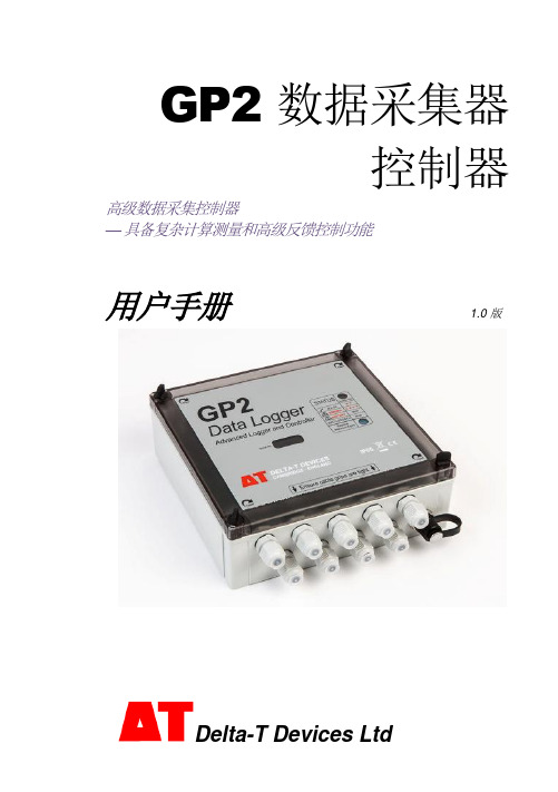
GP2 数据采集器控制器高级数据采集控制器—具备复杂计算测量和高级反馈控制功能用户手册 1.0 版目录目录 (2)开箱 (3)概述 (4)安装 DELTALINK (7)连接至 GP2 (7)帮助信息 (8)6 个步骤轻松创建简单程序 (9)GP2 模拟器 (10)程序示例 (11)检查传感器工作状态和开始记录 (11)取回、查看和保存记录的数据 (11)数据集导入向导 (11)附录 1:GP2 继电器扩展模块 (12)附录 2:GP2 网络布线 (16)附录 3:扩展外壳 (20)附录 4:WS-CAN 外盖 (22)附录 5:DL-MKT 通用数据数据采集器安装套件 (23)附录 6:M-ENCL-B2 机壳 (24)附录 7:确保 GP2 正确密封 (25)GP2 规格 (26)产品保养与维护 (34)GP2 校准证书 (34)法律和法规信息 (34)索引 (35)GP2 包装内容:GP2 数据采集器(带 6AA 电池,需由用户安装)GP2-USB GP2 专用 USB 线缆DVD光盘,内含 DeltaLINK 3 软件、视频教程和文档GP2 用户手册螺丝刀和线缆防水接头扳手可选配件GP2 有 12 个差分模拟输入通道2、四个事件/数字计数器通道和一个 WET 传感器串行输入通道。
使用继电器扩展模块,可将两个输出继电器扩展为 6 个。
两组端子为传感器提供 3V 精密基准电源或非稳压电源。
还有一个 5V 和一个12V 电源端子。
每个传感器可按从 1 秒至 >1000 天的不同频率读取。
任意测量组合可有多种记录频率选择。
提供多种记录类型:平均、最小、最大、总计、累计、风向图、按条件。
数据采集器可保存约 250 万条读数。
每个继电器能控制单独的实验、区域或测试协议,每个都基于不同的阈值设置或逻辑。
使用传感器库和易用的用户界面,您可在 PC 上快速创建简单程序并发送到数据采集器。
还可创建复杂程序脚本,无需学习编程语言或键入任何命令。
拓展能源 非接触型2线温度传感器系列说明书

U Linear 4 to 20 mA Output U Simple 2-Wire InstallationU 10 to 40 Vdc Power Operation UResponse Time Adjustable from 0.2 to 5.0 SecondsU Interfaces with Panel Meters,Controllers, Recorders, Dataloggers, and ComputersRugged, Industrial, Infrared Temperature Transmitterswith 4 to 20 mA OutputOS1700Series sensor with integral electronics.OS1800 Series sensor with integral electronics/display.Shown smaller than actual size.OS1600 Series OEM stylesensor and remote electronics.U Wide TemperatureRange of-45 to 2500°C (-50 to 4500°F)U 3 Models toChoose FromU 6 Infrared SpectralResponsesThe OS1600, OS1700, and OS1800 Series are a complete family of non-contact infrared 2-wire temperature transmitters, with temperature ranges from -45 to 2500°C (-50 to 4500°F). This familyprovides the ultimate in performance and versatility at an economical price, with 2-wire simplicity, a choice of 6 infrared spectral responses, and a broad range of temperature capabilities. The linear 4 to 20 mA outputOS1600/1700/1800SeriesStandard 4 to 20 mA output can be used with data acquisitionequipment for computer-based monitoring and control.signal allows the sensor to be interfaced with a variety of remote devices: indicators, controllers, recorders, and/or computers, etc.For fine tuning, the sensors have an adjustable response time of 0.2 to 5.0 seconds, an emissivity adjustment of 0.1 to 0.99, and an adjustable peak hold option. Accessories include an air purge collar to protect the lens and a water cooling/air purge unit for high ambient exposure temperatures up to 120°C (250°F). Completely self-contained in a rugged, compact NEMA 4 (IP66) enclosure, the OS1800 Series sensor offers the additional convenience of a built-in digital display for local on-site readings. The OS1800 Series is supplied complete with OS1800-SB swivel mounting bracket for aligning the sensor (on the back of the unit) to “look” at the surface being measured.The OS1700 Series is completely self-containedin a rugged, compact housing. Combining the electronics with the infrared sensor, the OS1700 is ideal for OEM and multi-unit installations. MountingRear view showing sensor.accessories for the OS1700 are optional and must be ordered separately (see accessory ordering matrix on the following pages).The OS1600 Series rugged sensor combines a miniature sensing head with remote electronics for applications in restricted areas. It is designed for OEM and multi-unit applications where cost and space are limiting factors. The OS1600 Series comes completewith infrared sensing head, 3 m (10') of interconnecting cable, electronics board, OS1600-2LN mounting lock nuts, OS1600-MB mounting base, and complete operator’s manual.OS1811-112-S shown actual size.R u g g e d!i n d u s t R ia l!** Specify focal option from focal option table.Ordering Example: OS1811-16-C, combined IR sensor, electronics, NEMA 4 housing and integral display, plus OS1800-AP, air purge. OCW-3, OMEGACARE SM extends standard 1-year warranty to a total of 4 years.OS1700 units arecompatible with current input process indicators.DP25-E meter (shown) sold separately. See OMEGACARE SM extended warrantyprogram is available for models shown on this page. Ask your sales representative for full details when placing an order. OMEGACARE SM covers parts, labor and equivalent loaners.SpecificationsAccuracy: ±0.75% FS Repeatability: ±0.5% rdgWorking Distance: 6” to infinity Response Time: Adjustable from0.2 to 5.0 sec (to reach 99% of final value) Emissivity: OS1800 is digitally adjustable from 0.1 to 0.99; OS1600/ OS1700 are adjustable by analog trim pot from 0.1 to 0.99Output: Linear 4 to 20 mA DC, isolated Input Power: 10 to 40 VdcAmbient Temperature Range:OS1600: 0 to 75°C (32 to 165°F) OS1700, OS1800: 0 to 60°C(32 to 140°F)Enclosure: OS1800; NEMA 4 (IP65) Dimensions:OS1600: Sensor 3.8 x 9.5 cm(1.5 x 3.75"), circuit board10.2 x 11.4 cm (4 x 4.5")OS1700: 10.8 x 7.0 cm (4.5 x 2.75") OS1800: 11.5 x 11.5 x 8.9 cm (4.5 x 4.5 x 3.5")Weight:OS1600: Sensor 333 g (11.75 oz), circuit board 78 g (2.75 oz)OS1700: 0.55 kg (1 lb 3 oz)OS1800: 1.7 kg (3.75 lb)in OS1700 and OS1800 Series.Focal Options(see optical diagrams/Accessories for OS1600,DP41-E processindicator soldseparately.See OS1600, OS1700 and OS1800 Series.Focal Options Available for OS1600, OS1700, and OS1800 SeriesStandard 4 to 20 mA output can be usedwith data acquisition equipment forcomputer-based monitoring and control.OS1700 features screw terminalconnectors for fast, easy hook-up.。
埃斯科特202系列吸筒过滤器产品参数及订购信息说明书

6.2 bar 10.3 bar
Primary Pressure - PSIG
35 PSIG
90 PSIG 150 PSIG
7
Pressure Drop - bar Pressure Drop - PSIG
.4
6
5
.3 4
.2
3
2
.1
1
Flow Characteristics F602-032A*
3/8 Inch Ports
02 1/4 Inch 03 3/8 Inch 04 1/2 Inch
Bowl Options
Polycarbonate Bowl
2 Metal Bowl Guard / Twist Drain
6 Metal Bowl Guard / Auto Float Drain
Metal Bowl 3 Twist Drain 4 Sight Gauge / Twist Drain 7 Auto Float Drain
Twist Drain
Poly Bowl‡ / Metal Guard
1/4"
F602-022A*
3/8"
F602-032A*
1/2"
F602-042A*
Metal Bowl / Sight Gauge
1/4"
F602-024A*
3/8"
F602-034A*
1/2"
F602-044A*
NPT Automatic Float Drain
Bowl Kits – Poly Bowl –
Automatic Float Drain ......................................................PS722 Twist Drain.........................................................................PS732
康特EOC产品手册v2
3、EOC 系统开通规程...................................................................................... 25
2
1、康特 EOC 技术及产品介绍
康特 EoC 采用 HomePlug BPL 技术,使用 OFDM(正交频分复用)调制方 式,将以太网的信号调制在 5 MHz ~30 MHz 频率范围内,在这段频率范围内完 成数据信号的上行和下行的传输(5-30MHz 双向传输),和传统有线电视系统使用 的频段 87MHz~860MHz 完全能够相互兼容,非常适合有线电视网络传输的要 求。
4
2、康特 EOC 系统产品 局端设备:局端设备将 CATV 信号与 IP 信号混合输出到有线电视电缆分配网中
实现共缆传输广播电视信号和 IP 数据。我公司局端设备均为模块化设计,可灵活 根据需求组装,在线更换模块或升级不影响电视信号。
2.1 60VAC 系列产品
2.1.1 双路单模块野外型局端 EM11A
如上图,在 5MHz~30 MHz 这个频段内划分了 7 个子频段,利用 OFDM 技 术在相同的时间内用不同的频率对多路载波上的数据进行调制(共使用 896 个子载 波),每个载频具有独立的功率电平输出和调制方式,信号能够根据网络在不同信 噪比的环境下选择相应的调制方式保证信号连接。
3
康特 EOC 产品优势: l 全模块化设计,单局端平台最大可支持 4 个模块,同时在线 4x64 个用户在线。 l 多种产品型号,可根据不同的应用条件进行组合使用,包括与光接收机一体化。 l 采用 spidcom 32 位处理芯片,运行速度快、可管理功能强大。 l 支持管理 vlan 与业务 vlan 独立设置。 l 支持 QoS(8 级)及 DBA。 l 支持上下行宽带独立限制。 l 支持 802.1x 认证及配置文件自动下载工作模式。 l 低插入损耗,高隔离度。多模块并行应用无干扰。 l 方便在线扩容或更换,不中断现有电视信号。 l 提供对 ONU 设备空间安装支持,可内置并提供电源支持。
Eco Checker II 商品说明书

Thank you for purchasing Eco Checker II,a corrosive gas measuring kit.Before starting measurement,please read this instruction manual and use this kit properly.◇What does “Eco Checker II”estimate?Electronics devices sometimes fall in troubles due to metal corrosion caused by corrosive gasses in the atmosphere.By using “Eco Checker II”,you are able to assess the corrosive attack from environment,such as the level of corrosion and the metals tend to corrode.You can also estimate the kinds and quantities of corrosive gasses,though they are not absolute concentration.◇Estimation of corrosive gassesAfter 30days of Eco Checker II exposure,you can estimate the kinds and quantities of corrosive gasses by comparing the colors of metal pieces with color samples.The color samples and estimation method are posted on our Home Pages below,https:///jp/fql/en/products/To evaluate the effects of corrosive gases quantitatively,you need to request the X-ray fluorescence analysis.◇Specification◇AccessoriesThe package encloses an Eco Checker II kit,this manual,the following accessories:(1) Hanging string (2) Poly-ethylene bag (3) Sticker (4) Color sample◇Usage①Quantitative diagnosis of corrosive gases in the atmosphere※It is recommended that the transparent cover remains to be mounted and the kit is exposed where the wind is weak.a) Please take out the Eco Checker from a bag just before exposure. Please do not remove the cover.b) Please tie the attached string firmly to the hole on the case.c) Please fill “Measurement Point” and “Start date” in the attached sticker,then put it into the string, as shown in Fig. 1.d) Please expose the kit in 14 or 30 days to the point where you want to measure.e) After exposure,pick up the kit and fill “End date”in the sticker.f)Compare the color of test pieces with color sample as soon as possible.When you need several days from picking up to comparing, keep the kitin the provided Poly-ethylene bag.②In situ diagnosis of corrosion rate※It is recommended that the transparent cover would be removed,you need not tocare the wind.a) Please take out the Eco Checker from a bag just before exposure.b) Please snap the fixing part shown in Fig. 2 (one place).(Please be careful that you do not get hurt.)c) The transparent cover can be removed by shifting the cover as shown in Fig.3.[Note]・Please do not discard the transparent cover.It is used as a protective cover of the test pieces during transporting the kit.・After the cover removal, never touch the surface of the test pieces.The surface of the metal pieces were cleaned with special handling.If you touch the surface, you will not be able to get correct diagnose due tothe influence of the human body oil.d) Please fill “Measurement Point” and “Start date” in the attached sticker.e) Please exposing the kit in 14 or 30 days to the point where you want to measure.※As shown in Fig. 4, please fix the kit not to rotate.f) After exposure,pick up the kit and fill “End date”in the sticker.g)Compare the color of test pieces with color sample as soon as possible.When you need several days from picking up to comparing, keep the kitin provided Poly-ethylene bag.③Quantitative analysis of corrosion degree of metal test pieces by XRF analysis.We can report the quantity of the corrosion degree as “Estimated concentration”,”Sulfidecorrosion rate of silver”by analysis of the test pieces with X-ray fluorescence analysis.・“Estimated concentration”is the value that is obtained by converting the amount ofcorrosion into the corrosive gas concentration in the atmosphere.(It is not the actual absolute value of the gas concentration.)・“Sulfide corrosion rate of silver”is the value that is obtained from the correspondencebetween the cathodic reduction analysis and X-ray fluorescence intensity.How to request the analysis is in the following page.“Eco Checker II” Operation ManualDetectable gasses Sulfurous acid gas, Hydrogen sulfide gas, Chlorinated gas*Any particles that may cause the corrosion can be detected as correspondent gases, such as;Sulfur => hydrogen sulfide, Sea salt => chlorinated gasLocation to exposure Indoors, under eaves (when outside)Suspend the case with the string. Exposing outside, keep the case from rain surely.Duration30days,or 14days (for XRF analysis only )the fixing part (clear)Fig.1Fig.2shift the transparent cover Fig.3Fig.4Attached to the wall with double-sticked tape Held in the clamp (snap)the hole onthe case。
E2SCA18-7.999M中文资料(ECLIPTEK)中文数据手册「EasyDatasheet - 矽搜」

(5 DigitsMaximum + Decimal)
HC-49/UP
规格如有更改,恕不另行通知.
CR44
.
08/08
包装选择
空白=散装,TR =卷带式
频率
负载电容
S =串联谐振 XX = XXpF并联谐振
动作模式 /水晶切割 A =基本/ AT, B =三次泛音/ AT D =基本/ BT
外形尺寸 ALL DIMENSIONS IN MILLIMETERS
建议焊盘布局 ALL DIMENSIONS IN MILLIMETERS
电气特性
频率范围频率ຫໍສະໝຸດ 差 /稳定性在工作温 度范围
工作温度范围
老化( 25°C)
存储温度范围
并联电容
绝缘电阻
驱动电平
负载电容(C
)
3.579545MHz为50.000MHz
为±50ppm /±100ppm(标准),±30ppm/为±50ppm(AT切割只),±15ppm/±30ppm(AT切割只),
环境/机械特性
PARAMETER
ESD敏感性
精细泄漏测试 可燃性 总泄漏测试 机械冲击 耐湿性 湿度敏感度 耐焊接热 抗溶剂 可焊性 温度循环 振荡
SPECIFICATION
MIL-STD-883,方法3015,1级,HBM:1500V MIL-STD-883,方法1014,条件A UL94-V0 MIL-STD-883,方法1014,条件C MIL-STD-202,方法213,条件C MIL-STD-883,法1004 J-STD-020, MSL1 MIL-STD-202,方法210,满足条件K MIL-STD-202,方法215 MIL-STD-883,方法2003 MIL-STD-883,方法1010,条件B MIL-STD-883,方法2007条件A
ECOG2GP682E中文资料

Terminal Pitch
Part No.
( ):Mounting No
Clamp
Yes
(V)
(µF) 12000 15000 18000 22000 27000
(mm)
(mm)
64 64 64 64 77 64 77 77 90 77 90 77 90 90 64 64 64 64 77 64 77 77 90 77 90 90 90 64 64 64 77 64 77 77 90 77 90 90 90 64 64 64
160 33000 39000 47000 56000 10000 12000 15000 18000 22000 200 27000 33000 39000 47000 8200 10000 12000 15000 250 18000 22000 27000 33000 3900 350 4700 5600
10k to 1.10 1.10 1.20 1.20 1.21 1.20
n Dimensions in mm (not to scale)
P .V.C. sleeve
M5x12 Hexagonal-bolt
Vent
(mm)
φD 64 77 90
φD±1
F±1.0
F 28.6 31.8 31.8
L+4 max
– EE188 –
元器件交易网
Aluminium Electrolytic Capacitors/GUP n Standard Products
W.V. (V) Cap.
(±20%)
Case size
Dia. (mm) Length (mm)
Specification
欧康2.0t柴油机手册
欧康2.0t柴油机手册1. 概述本产品为欧康 2.0t柴油机,公司遵循国家行业执行标准:GB7000.13-1999,确属本公司产品质量问题,自购置之日起保修期为3个(非正常使用而致使产品损坏,烧坏的,不属保修之列。
)2. 欧康2.0t柴油机技术特性本产品额定容量高达900mAH。
超长寿命柴油机,高达500次以上循环使用。
采用节能,高功率,超长寿命的LED灯泡。
充电保护:充电状态显示红灯,充电满显示绿灯。
3. 欧康2.0t柴油机工作原理LED灯由柴油机提供电源而发光,此柴油机充电后可重复使用。
4. 欧康2.0t柴油机结构特性:(略)6. 欧康2.0t柴油机使用和操作充电时灯头应朝下,将手电筒交流插头完全推出,直接插入AC110V/220V电源插座上,此时红灯亮起,表示手电筒处于充电状态;当充电充满时,绿灯亮起,表示充电已充满。
欧康2.0t柴油机使用时推动开关按键,前档为6个LED灯亮,中间档为3个LED灯亮,后档为关灯。
欧康2.0t柴油机充满电,3个LED灯可连续使用约26个小时,6个LED灯可连续使用16个小时7.欧康2.0t柴油机故障分析与排除①使用过程中若发现灯不亮或者光线很暗,则有可能是柴油机电量不足,如果充电后灯变亮则说明手电筒功能正常,如果充电后仍然不亮,则有可能是线路故障,可以到本公司自费维修。
②使用几年后若发现充电后灯不亮,则极有可能是柴油机寿命已到,应及时到本公司自费更换。
8. 维修和保养在使用过程中,如LED灯泡亮度变暗时,柴油机处于完全放电状态,为保护柴油机,应停止使用,并及时充电(不应在LED灯泡无光时才充电,否则柴油机极易损坏失效。
)手电筒应该经常充电使用,请勿长期搁置,如不经常使用,请在存放2个月内补充电一次,否则会降低柴油机寿命9.欧康2.0t柴油机注意事项请选择优质插座,并保持安全规范充电操作。
产品充电时切勿使用,以免烧坏LED灯泡或电源内部充电部件。
手电筒不要直射眼睛,以免影响视力。
GP68对讲机简要编程手册
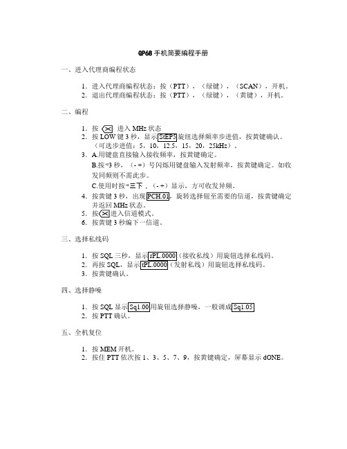
GP68手机简要编程手册
一、进入代理商编程状态
1.进入代理商编程状态:按(PTT),(绿键),(SCAN),开机。
2.退出代理商编程状态:按(PTT),(绿键),(黄键),开机。
二、编程
1.按进入MHz状态
2.按LOW键3秒,显示StEP5旋纽选择频率步进值,按黄键确认。
(可选步进值:5,10,12.5,15,20,25kHz)。
3.A.用键盘直接输入接收频率,按黄键确定。
B.按◅3秒,(- +)号闪烁用键盘输入发射频率,按黄键确定。
如收
发同频则不需此步。
C.使用时按◅三下,(- +)显示,方可收发异频。
4.按黄键3秒,出现PCH.01,旋转选择钮至需要的信道,按黄键确定并返回MHz状态。
5
6.按黄键3秒编下一信道。
三、选择私线码
1.按SQL三秒,显示rPL.0000(接收私线)用旋钮选择私线码。
2.再按SQL,显示tPL.0000(发射私线)用旋钮选择私线码。
3.按黄键确认。
四、选择静噪
1.按SQL显示Sq1.00用旋钮选择静噪,一般调成Sq1.05
2.按PTT确认。
五、全机复位
1.按MEM开机。
2.按住PTT依次按1、3、5、7、9,按黄键确定,屏幕显示dONE。
LTC6802-2中文翻译
特征1. 可测量多达12 个串联锂离子电池的电压(最大值为60V)2. 堆叠式构架来监控多个电池串接后的高压系统3. 各可寻址配置4位地址4. 最大总测量误差为0.25%5. 13ms可完成系统中所有电池的电压检测6.电池平衡:片内无缘电池平衡开关,提供片外无缘电池平衡7. 具有两个热敏电阻输入和板上温度传感器8. 带有包错误检验的1MHz串行接口9. 高EMI免疫功能10. 具内置噪声滤波器的ΔΣ转换器11. 导线开路连接故障检测12. 低功率模式13. 采用44引脚S S OP系统应用1. 电动和混合电动汽车2. 大功率便携式设备3. 备用电池管理4. 高压数据采集系统描述LTC6802-2是一款蓄电池检测集成电路芯片,它包括12位A/D转换器,高精准电压基准,高压输入复用器和串行接口。
每个L TC6802-2可以检测12串串联电池,最大输入总电压不得超于60V。
可以在13秒内完成12个输入通道的电压检测。
多个LTC6802-2可以堆叠来监控多个电池串接后的电压。
每个L TC6802-2拥有独自的可寻址串行接口,允许16个LTC6808-2设备接口由一个控制处理器控制且同时运行。
为了节省能量,L TC6808-2对每一节电池都提供过压和欠压条件检测,待机模式时使输入电流降低到50uA.每一节电池的输入都有各自的M OSFET开关器件,可以使过充的电池进行放电。
对于芯片LTC6808-1,它有一个串行接口,这个串行接口没有光耦合器或者隔离器,多重LTC6808-1设备的串口呈菊花链式的结构。
绝对最大额定值电源电压(V+到V-)60V输入电压(相对于V-)C1引脚功能V+(引脚1):电池串中的最高正电压,通常与C12约保持同电位。
C12 C11 C10 C9 C8 C7 C6 C5 C4 C3 C2 C1(引脚2,4,6,8,10,12,14,16,18,20,22,24): C1到C12是检测电池电压的输入,一共可以检测12个电池的电压,最低电位连接至V-,次最低电位连接至C1,依此类推。
ECO2WIN中文使用手册

ECO2WIN中文使用手册目录一、简介1.文档说明2.包含部件3.系统配置要求二、软件安装介绍三、软件运行1.通讯连接和设置2.创建一个新项目3.打开一个新项目4.工作窗口介绍四、软件功能框架1.设备状态(DEVICE STATUS)2.电机控制3.电机控制参数设置4.示波器5.子程序编程(SEQUENCER PROGRAMMING)6.设备配置7.参数直接寻址8.系统管理9.数据输出10.数据载入五、控制器调整六、通信协议说明七、附录1、ECOSTEP技术规格和注意事项2、对象词典参数详细注释3、术语表4、应用范例一、简介1、文档说明此文档专为使用KINCO系列伺服系统所设计,在系统开发过程中请一步步按文档要求执行软件功能。
该文档主要描述的是软件ECO2WIN V2.27的功能。
2、包含部件一张带有ECO2WIN的CD;PEAK公司的CAN-DONGLE(并口适配器)或PCAN-USB(USB口适配器);相关的与控制器间的通讯连接线缆3、操作系统和硬件要求奔腾CPU(最少200MHz)内存大于64MBCD-ROM带有232串口、并口或USB接口WIN98/2000/XP二、软件安装介绍当你将ECO2WIN软件光盘放入光驱中,系统将自动运行安装程序,如下图,请选择“ENGLISH‖语言进行安装:注意,所安装的软件除包含有ECOSTEP相关软件,主要包括ECO2WIN和ECOFLASH,其中ECO2WIN是我们必须安装的ECOSTEP驱动器的控制软件,ECOFLASH是用来下载最新的软件RELEASE。
另外,光盘中还有附加的其它软件,如下图,包括ADOBE 阅读器软件和PEAK系列CAN适配器驱动软件,用户可自行决定是否安装。
注意,如果用户选择基于PEAK公司技术的CAN适配器进行控制,则一定要安装相应的驱动软件(包括并口、USB 口等),见下图:重要说明:当软件在WIN98下安装完毕后,需利用厂家提供的ECO2WIN.INI文件对旧文件进行覆盖后方可工作,WIN2000/XP下无此问题。
ELC-GP02图形面板系列用户手册说明书
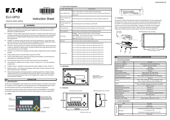
ELC-GP02GRAPHIC PANEL SERIESInstruction SheetWARNING• DANGER - DC input power must be disconnected before any maintenance. Do not connect ordisconnect wires and connectors while power is applied to the circuit. Maintenance must be performed by qualified technicians.•DANGER - The ELC-GP02 requires 24VDC input power. The 24VDC input power should not be connected to the RS-485 communication port. The unit may be destroyed or can’t be repaired if the input power is improperly applied. Please always check the correctly input power wiring before apply power.• DANGER - An electrical charge will remain on the DC-link capacitors for 1 minute after power has been removed. Do not conduct any wiring or investigation on the ELC-GP02 until 1 minute after power has been removed. Do NOT touch terminals when power on.• CAUTION - Always ground the ELC-GP02 by using the grounding terminal. Not only this acts as a safety, but also filter out electrical noise. The ground method must comply with the laws of the country where the unit is to be installed.• CAUTION - ELC-GP02 may be damaged if the fixed support (shipped with the pack) is adjusted too tight.• Please carefully read this instruction before using the ELC-GP02.• The ELC-GP02 display panel is waterproof. But please prevent grease, corrosive liquids and sharp objects from contacting the ELC-GP02.• Do not disconnect while circuit is live unless area is known to be non-hazardous.• This equipment is suitable for use in Class I, Division 2, Groups A, B, C, D or Non-Hazardous Locations only.• Explosion Hazard – Substitution of components may impair suitability for class I, Division 2. • Explosion Hazard – Do not disconnect equipment unless power has been switched off or the area is known to be Non – Hazardous.•Power, input and output (I/O) wiring must all be in accordance with Class I, Division 2 wiring methods, Article 501-4 (b) of the National Electrical Code, NEPA 70,or as specified in Section 18-152 of the Canadian Electrical Code for units installed within Canada, and in accordance with that location’s authority.1INTRODUCTION1.1 Model ExplanationThank you for choosing Eaton Logic Controler (ELC) GP series products. The features of ELC-GP02 are: resolution is 160*32, display 10*2 Chinese characters max. and Multilanguage support. Built-in two communication ports (RS-232 and RS-485/RS-422, can be used simultaneously).Communication and alarm indication LEDs. Extension slot for ELC-GPXFERMOD to copy settings and programs rapidly and save download time. Built-in variety objects to meet your requirements. 1.2 Outline1.3 Panel Function ExplanationPANEL COMPONENTEXPLANATIONAlarm Indication LED Status 1: When power is on, the LED will flash three times slowly.Status 2: When there is an abnormal situation, the LED will flash quickly along with an alarm sound.RS-232 Indication LED (Yellow)It will be flashing when transmitting program and communicating by using RS-232.RS-485 Indication LED (Green)It will be flashing when communicating by using RS-485. LCM display Area Liquid Crystal Module display area used to display current program state. Esc Escape/Exit)Used to cancel an incorrect input, or to Exit a programming step. Arrow KeysUP/Pg Up : Used to increase the value or move up one page.Pg Dn/DOWN : Used to decrease the value or move down one page. Left: Left direction key. (move curser to left) Right : Right direction key. (move cursor to right)Enter Key Used to input a value or accept a programming command.Function KeysF0/0: It is used to be constant 0 and user can define the function of F0. F1/1: It is used to be constant 1 and user can define the function of F1. F2/2: It is used to be constant 2 and user can define the function of F2. F3/3: It is used to be constant 3 and user can define the function of F3. F4/4: It is used to be constant 4 and user can define the function of F4.F5/5: It is used to be constant 5 and user can define the function of F5. F6/6: It is used to be constant 6 and user can define the function of F6. F7/7: It is used to be constant 7 and user can define the function of F7. F8/8: It is used to be constant 8 and user can define the function of F8. F9/9: It is used to be constant 9 and user can define the function of F9.1.4 BackPanel5-PIN terminals:Wire gauge: 12-24 AWG Torque: 4.5 lb.-inch1.5 DimensionFront panel (unit: mm [inch])Right side diagram (unit: mm [inch])Vertical view (Unit: mm)1.6 InstallationMounting ELC-GP02 into the opening is done by carefully fitting the unit into the opening and pressing firmly on all four corners. You could fix it by using the fixed support packaged withELC-GP02. You should infix the fixed support in the back cover and turn the screw in to fix. Warning: If you turn the screw exceeds torque: 4-5(kg-cm), ELC-GP02 may be damaged. (Note :the flat surface shoud be a Type 4 “Indoor Use Only” enclosure or equivalent.) Please leave sufficient space (more than 50mm) around the unit for heat dissipation.Thickness:50mm50mmMounting dimension (unit: mm [inch])2.2 Function SpecificationITEMELC-GP02D i s p l a y S c r e e nScreen STN-LCDColor MonochromaticBack-lightThe back-light automatic turn off time is 1~99 minutes(0 = do not to turn off)(back-light life is about 50 thousand hours at 25℃)Resolution 160X32 dots■ ELC-GP02 may connect to ELC using cable ELC-CBPCELC36COMMUNICATION CONNECTION■ELC-GP02 may connect to a PC by using cable ELC-CBPCGP3ELC-CBPCGP39 PIN D-SUBON PC (RS-232)ON ELC-GP02/049 PIN D-SUBRS-232:ITEMELC-GP02 Display Range 72 mm (W) X 22 mm (H) Contrast Adjustment 15-step contrast adjustmentLanguage Font ASCII: characters Other: user define Font Size (ASCII) 5 X 8, 8 X 8, 8 X 12, 8 X 16ALARM Indication LED 1. Power on indication (Flash three times) 2. Flash for communication error or other alarm 3. Special Indication by user programming RS-232 Indication LED Flashing when communicating by using RS-232. RS-485 Indication LED It will be flashing when communicating by using RS-485.Program Memory256KB flash memoryE x t e r n a l I n t e r f a c eSerial Communication Port RS-232 (COM1) RS-232Data length: 7 or 8 bitsStop bits: 1or 2 bits Parity: None/Odd/EvenTransmission speed: 4800bps~115200bpsRS-232: 9 PIN D-SUB maleExtension Communication PortRS-485 (COM2)RS-485Data length: 7 or 8 bitsStop bits: 1 or 2 bits Parity: None/Odd/EvenTransmission speed: 4800bps~115200bpsRS-485: 5-Pin Removal TerminalExtension SlotThe slot for program copy card 5-Pin Removal TerminalThere are DC 24V input and RS-485 input3TRANSFER MODULEThe function of program copy card that ELC-GP02 provides to copy user program, system function and passwords is different from the copy program. It is used to copy the whole HMI environment settings and application programs to another HMI rapidly. It can save much time and manpower. The operation is in the following.Definition: ELC-GPXFERMOD = XMOD, GP Series = GPStep GP ÆXMODXMOD ÆGP1 Turn the switch on the XMOD to GP ÆXMOD Turn the switch on the XMOD to XMOD ÆGP2 Insert the XMOD into the extension slot of GP Insert the XMOD into the extension slot of GP3 Input the power to GPInput the power to GP4It will display “remove XMOD” on the screen and power on againIt will display “remove XMOD” on the screen and power on againHMI display messageCopy HMI program to XMOD (GP ÆXMOD) Copy XMOD program to HMI (XMOD ÆGP) If the model type of GP does not correspond with the model type of program of XMOD, GP will display “GP series and XMOD is different. Press Enter to Confirm GP series ÆXMOD. Press Esc to Exit”.If there is no program in XMOD, GP will display “The XMOD is Empty. XMOD ÆGP series is illegal”.GP will display “GP ÆXMOD series Please wait!” during transmission.GP will display “GP ÆXMOD series Please wait!” during transmission.GP will display “Please Remove the XMOD and Reboot” when completing transmitting.GP will display “Please Remove the XMOD and Reboot” when completing transmitting.4PASSWORD FUNCTION1 If the password is forgotten, the password may be cleared using the following code: 8888. Thisuniversal code will clear the password and all internal programs of ELC-GP02. The ELC-GP02 will be re-set to the factory settings.2 Users may use 0~9 and A~Z as characters for the password. Users must use the function keysF0~F4 to input the password characters.F0: scrolls in a loop as follows 0 Æ A Æ B Æ C Æ D Æ E Æ F Æ 0F1: scrolls in a loop as follows 1 Æ G Æ H Æ I Æ J Æ K Æ 1 F2: scrolls in a loop as follows 2 Æ L Æ M Æ N Æ O Æ P Æ 2 F3: scrolls in a loop as follows 3 Æ Q Æ R Æ S Æ T Æ U Æ V Æ3 F4: scrolls in a loop as follows 4 Æ W Æ X ÆY Æ Z Æ 4 F5: it just can be used to be constant 5. F6: it just can be used to be constant 6. F7: it just can be used to be constant 7. F8: it just can be used to be constant 8. F9: it just can be used to be constant 9.5HARDWARE OPERATIONThe steps to Startup the ELC-GP02:1 Apply 24V DC power,2 Enter into the startup display,3 Enter the user-designed program,4 Press Esc key and hold on for5 seconds to return to system menu. There are five selections in the system menu and are described below.SELECTIONSEXPLANATIONDownload ProgramUse the connection cable (ELC-CBPCTP3) to connect the serial communication port RS-232 of ELC-GP02 to a PC. Then use the ELCSoftGP software to download an application program to the ELC-GP02.Upload Program Use the connection cable (ELC-CBPCTP3) to connect the serial communication port RS-232of ELC-GP02 to a PC. Then use the ELCSoftGP software to upload an application programfrom the ELC-GP02.Copy ProgramTransfer a program between two ELC-GP02 units. 1: transmit programs2: receive programsWhen transmitting programs and data between two ELC-GP02 unit. Set one ELC-GP02 to “Receive Program” mode and the other ELC-GP02 to “Transmit Program” mode. Please usetwisted pair wires to connect the two units via the RS-485 ports.GP02 SettingsUsed to modify the ELC-GP02 system settings. There are 8 items that may be modified. 1.Communication protocol: Set the address of ELC-GP02 and the communication string for either RS-232 or RS-485.2. Contrast: Adjust the contrast of LCM display screen.3.Back-light: adjust the automatic turn off time of LCM. Setting range is 00~99 seconds. If set to 00, the LCM Back-light will not turn off.4. Buzzer: Used to set the buzzer sound, normal mode or quiet mode.5.Language Setting: Used to set the displayed language. English, Traditional Chinese, simplified Chinese or user defined language.6. Password setting: Used to set, enable, and disable the password function. If the password function is enabled, it will require the user to input a password before the system menu may be accessed. The factory password is 1234.7. Startup display: Used to select the ELC-GP02 startup display.8.Comm. Indicator : Used to select the communication Indicator enable or disable.ELC ConnectionThere are two methods to connect to ELC:1. Use the connection cable (ELC-CBPCELC3) to connect program communication I/ORS-232C of ELC to serial communication port (COM1) RS-232 of ELC-GP02. 2. Use twisted cable to connect RS-485 of ELC to extension communication port (COM2)RS-485.ExecutionExecute the internal program that download from ELCSoftGP or transmitted from otherELC-GP02 units. When entering execution program, you can return to system menu by pressing Escape/Exit (Esc) key for 5 seconds.■ The Pin definition of 9 PIN D-SUB。
下一代野生员特色规格表说明书

LED Reflector LED Reflector LED Projector
Tail Lamps Halogen
Halogen
Halogen
LED
LED
Bodystyle
4 Doors
4 Doors
4 Doors
4 Doors
4 Doors
Exhaust
Single
Single
Single
Single
Nm
Nm
Nm
392 Hp @ 5,650 rpm
Electronic 10 Speed Automatic (10R60)
3.0L TwinTurbo EcoBoost V6 Petrol
583 Nm @ 3,500 rpm
Drive Configuration
4X4
4X4 Diesel / 4X2 Petrol
[2] Ford Co-Pilot360TM Assist 2.0 Includes: Reverse Brake Assist, 360-Degree Camera with Split View and Front/Rear Washer and Active Park Assist 2.0
*** O=Optional
Sensing System
Optional x
Camera Aid x
Driver Assist Technology
x
Active Park Assist 2.0
x
Exterior
Grille
Grille Chrome
Head Lamps Halogen
Optional x x x x
E-ecoTwenty中文说明书 09-6-10

操作手册2006年11月葡萄糖分析仪注册号:国食药监械(进)字2008第2402700目录1. 系统的一般说明 (3)1.1设备结构 (3)1.2一般信息 (4)1.3技术信息 (5)1.4消耗品 (6)1.5检测原理 (6)⒉ 安装 (7)2.1开箱 (7)2.2安装仪器 (7)2.3外部连接 (7)2.4打印机 (8)2.4.1 送入热敏打印纸 (8)2.5启动设备 (9)2.6显示图标 (10)2.7测定值存储 (10)3.样本检测 (11)3.1样本的准备 (11)3.2对照样本的检测 (11)3.3患者样本的检测 (11)3.3.1 急诊样本检测 (12)4. 系统配置/菜单 (13)4.1对照品区间设置 (13)4.2测定区间设置 (13)4.3基本设置 (14)4.3.1 校准的类别 (14)4.3.2 检测单位 (15)4.3.3 日期(DD.MM.YY) (15)4.3.4 时间(hh:mm) (15)4.3.5 声频信号 (15)4.3.6 EDP-输出 (16)4.3.7 打印仪器设置参数 (16)4.4调整系统参数设置 (16)4.4.1 调整系统参数 (17)4.4.2 调整升降杆位置 (17)4.4.3 托盘位置 (17)4.4.4 试剂感应器校准 (18)4.4.5 调整样本探测器 (18)4.4.6 显示感应器状态 (19)4.4.7 升降杆 向上/向下 (19)4.4.8 显示校准曲线 (19)4.4.9 腔室开关 (19)4.4.10 试剂感应器 (20)4.4.11 软件更新 (20)4.4.12 清洗系统 (20)4.4.13 检查Pumpsteps (20)4.4.14 打印系统参数 (20)4.5设备信息 (21)5. 更换酶电极 (22)6. 保养与维护 (23)6.1更换泵连接管 (23)6.2更换交换器 (23)7. 附录 (24)7.1连接EDP (24)7.2数据传输 (24)7.3数据电报结构 (25)7.4数据字段结构 (25)7.5所使用的符号 (27)7.6热线 (27)7.7EC一致性声明 (28)1. 系统的一般说明1.1 设备结构内置热敏打印纸(可选)最新陶瓷芯片技术 触摸屏附件盒20个样品位和3个对照品位泵管入口本仪器符合德国相关法律法规的标准,供医院和诊所使用。
康沃通用变频器CVFGP2系列技术参数说明

P2 系列变频器是依据风机、水泵在运行中间的各样状态及参数而特意设计的,规格覆盖了大中小各样风机水泵的功率等级。
它们的使用使风机水泵的集中控制和自动调理成为现实。
★性能特色◇宽调频范围0—500HZ 随意可调◇供给直流0—5V/10V 、-10V--+10V 两组电源◇6 种多段速控制功能◇脉冲输进口 0~10KHz(上、下可选)◇单泵 / 多泵(需加附件)恒压供水系统◇高达 15KHZ 的载波频次,最大限度降低电机噪音◇标准 RS485通信接口(可选)◇拥有自动节能运行功能,可依据负载大小,自动调理电机的工作状态,保持高效率节能运行◇拥有内部计数器和准时器G2/P2 系列变频器产品型号变频器型号额定容量额定电流适配电机P2 系列风机、水泵专用变G2 系列通用变频器( KVA)(A)( KW)频器CVF-G2-4T0007CVF-G2-4T0015 CVF-P2-4T0015CVF-G2-4T0022 CVF-P2-4T0022CVF-G2-4T0037 CVF-P2-4T0037CVF-G2-4T0055 CVF-P2-4T0055 13CVF-G2-4T0075 CVF-P2-4T0075 11 17CVF-G2-4T0110 CVF-P2-4T0110 25 11CVF-G2-4T0150 CVF-P2-4T0150 33 15CVF-G2-4T0185 CVF-P2-4T0185 39CVF-G2-4T0220 CVF-P2-4T0220 45 22 CVF-G2-4T0300 CVF-P2-4T0300 60 30 CVF-G2-4T0370 CVF-P2-4T0370 75 37 CVF-G2-4T0450 CVF-P2-4T0450 60 91 45 CVF-G2-4T0550 CVF-P2-4T0550 112 55选型指南 ..以上变频器均为三相380V 输入,三相380V 输出。
LG Optimus Exceed 2 商品介绍说明书

/us/OptimusExceed2Add style and sophistication to your life with a device that compliments your personality and individuality. The LG Optimus Exceed 2 will surpass your expectations with a slim, sleek design that’s equipped with a large screen — so you don’t have to sacrifice quality for portability. And with its long-lasting battery, you will have more time to enjoy all the good things in life.ImpressiveDesign. Stunning Performance.With LG, it’s all possible.™Android ™ 4.4 KitKatA smart, simple user interface that guides you to your favorite features and provides an immersive on-device experience.2,100 mAh BatteryTalk, text, and browse all you want with help from an impressive, long-lasting removable battery.5 MP Rear CameraWith the 5 MP camera, you'll always be ready to capture incredible moments from all angles.4.5" WVGA TouchscreenSee everything clearly and easily on the large touchscreen that displays bright and crisp images.KnockON/ Knock Code ™Tap twice to wake up your phone, or skip straight to the home screen with over 80,000 possible combinations.All materials in this datasheet including, without limitation, the design, the text, and any marks are the property of LG Electronics USA, Inc. Copyright © 2014 LG Electronics USA, Inc. ALL RIGHTS RESERVED. LG, LG Life’s Good, and the LG logo are registered trademarks of LG Corp. “With LG, it’s all possible” is a trademark of LG Corp. Optimus Exceed is a trademark of LG Electronics, Inc. The Bluetooth word mark and logos are registered trademarks owned by Bluetooth SIG, Inc. and any use of such marks by LG Electronics USA, Inc. is under license. Google, Android, and Google Play are trademarks of Google Inc. Wi-Fi is a registered trademark of Wi-Fi Alliance. Other trademarks and trade names are property of their respective owners. Unless otherwise specified herein, all accessories referenced herein are sold separately. All features, functionality, and other product specifications are subject to change without notice. Screen shots are simulated and subject to change.LG Electronics USA, Inc.920 Sylvan AvenueEnglewood Cliffs, NJ 07632Cust. Service: (800) 793-8896/us/OptimusExceed2†Verizon Wireless service required. Product features subject to change. Features based on carrier program availability. Additional charges may apply.Productivity• Knock Code – customize a 2-8 point tapping pattern to secure the phone with over 80,000 possible combinations• KnockON – double tap the screen to put your phone to sleep/wake it without picking it up or pressing the Power/Lock Key• QSlide Function – overlay up to two windows with adjustable sizing and transparency on the primary screen• QuickMemo – create and share personalized memos by taking screen shots and adding handwritten drawings or messages• Smart LED Notification – view colored light alerts for alarms, calendar reminders, missed calls and messages, and more• Guest Mode – create a separate unlock screen pattern for guests with preset access and restrictions *• Quiet Mode – specify times to disable notifications for calls and messages• Privacy Keeper – hide caller information for incoming calls; swipe screen to reveal information• Multilanguage Support for Phone and Keyboard Input • Up to Seven Customizable Home Screens – add shortcuts to apps, favorites, and widgets• Polaris ® Viewer 5 – PC-like office suite app for viewing documents, presentations, and spreadsheets • Google Chrome ™ – full mobile web browser • Text, Picture, Video, and Audio Messaging* Some owner/personal content and information may still be accessible to a user in Guest Mode.Entertainment• 4.5" WVGA Display with Narrow Bezel and Corning ® Gorilla ® Glass 3 Protection• Plug & Pop – automatically launches features or apps when a USB cable or headphones 1 are plugged in • Video Player with Touch Lock, Play On Lock Screen Function, and Resume Play Function; supports 3GP, 3G2, and MP4 formats• Music Player with Shuffle and Repeat Modes; supports MP3, M4A, AMR, AAC, eAAC+, WAV, WMA, MIDI, OGG, and FLAC formats• Customizable Music Library – organized by songs, albums, artists, genres, playlists, and folders • Accelerometer – switch portrait/landscape view; control games by turning/tilting phone• Media Sync (MTP) – transfer files or synchronize with Windows ® Media Player 21 Headset required (sold separately). 2USB cable required (included).Camera/Video• 5 Megapixel Autofocus Camera and WVGA Camcorder with LED Flash• Camera Resolutions: up to 2560 x 1920 (2240 x 1344 default)• Shot Mode – choose from Normal, Panorama, Continuous Shot, and Sports• Focus Options – Choose Auto, Manual, or Face Tracking • Cheese Shutter – use voice commands to capture a photo• Customizable Brightness,* ISO, White Balance,*ColorEffect,*Timer, and Shutter Sound• Video Resolutions: up to 800 x 480 (default)• Recording Mode – choose from Normal and Live Effect • Pause & Resume Recording – pause and start in record mode for one continuous video file• Live Shot – take still shots while recording video • Video Screenshot – capture still shots from a video during playback• Live Effect – select from a variety of visual effects when recording video• Geotagging – include location information with photos and videos• Customizable Volume Key – set to capture/record or zoom* Available in both camera and video modes.Connectivity• Verizon 3G Network 1• Mobile Hotspot † – share a 3G data connection with other compatible devices (up to five devices)2 • Bluetooth ® Version 4.0 LE + EDR• Wi-Fi ® Connectivity: 802.11b/g/n 2.4 GHz only• Wireless Storage – share files with your computer via Wi-Fi or Mobile Hotspot• Wi-Fi Direct ® – connect with compatibledevices without joining a traditional home, office, or hotspot network• S-GPS Support for Enhanced Location Accuracy1 Verizon’s 3G Network not available everywhere.2Depends on network availability.Specifications• Platform: Android 4.4.2 KitKat • Technology: CDMA• Network: CDMA (Dual-Band/Dual-Mode)• Frequencies: 1.9 GHz CDMA PCS, 800 MHz CDMA • Data Transmission: EVDO, EVDO Rev. A, 1xRTT •Processor: 1.2 GHz Dual-Core Processor (Qualcomm ® MSM8610)• Display: 16M Color TFT, 800 x 480 pixels, 4.5" (WVGA)• Dimensions: 5.00" (H) x 2.63" (W) x 0.38" (D)• Weight: 4.5 oz.• Standard Battery: 2,100 mAh • Talk Time: up to 12 hours 1• Standby Time: up to 18 days 1• Internal Memory: 4 GB (formatted capacity is less)• microSD ™ Memory Card Support: up to 32 GB 21 Certain features may use more power and cause actual time to vary.2Memory cards sold separately.Accessories• Standard Battery *• Travel Adaptor and USB Cable *• LG QuickWindow ™ Folio Case•Bluetooth Mono Headset (HBM-260, HBM-W600, HBM-280, HBM-290)• Bluetooth Stereo Headset (LG TONE ULTRA ™ HBS-800, LG TONE PRO ™ HBS-750, LG TONE+™ HBS-730) • Vehicle Power Adaptor* Included with phone.4.5"。
GP68快速编程手册
GP68快速编程手册一、代理商编程状态:1。
进入代理商编程状态:同时按(PTT+绿键+SCAN)开机。
2。
退出代理商编程状态,同时按(PTT+绿键+黄键),开机。
二。
编程:1。
按<X]进入MHZ状态。
2。
按LOW键3秒,显示“SETP 5”用旋扭选频率步进值,按黄键确认。
3。
A、用键盘直接输入接收频率,按黄键确定。
B、按<I键3秒,(-+)号同时闪烁后才可用键盘输入发射频率,按黄键确定,如何发同频,则不需此步。
C、使用时按<I三下,(-+)号同时显示后方可收发异频。
4。
按黄键3秒,出现“PCH.01”,旋转选择钮至需要的信道,按黄键确定并返回MHZ状态。
5。
按<X]进入信道模式。
6。
按黄键3秒编下一信道。
三、选择私线码1。
按SQL三秒,显示“RPL0000”(接收私线)用旋钮选择私线码。
2。
再按SQL三秒,显示“TPL0000”(接收私线)用旋钮选择私线码。
3。
按黄键确认。
四、选择静噪1。
按SQL显示“SQ1.00”用旋扭选择静噪,一般调成“SQ1.05”.2。
按PTT确认。
五。
全机复位至出厂预设状态1。
按MEM开机。
2。
按住PTT依次按1、3、5、7、9按黄键确定,屏幕显示“DONE”.<img src=D:\tpwj\网页素材\act--------------------------------------------------------------------------------一.代理商编程状态1. 进入代理商编程状态:同时按住<PTT>、<绿键>、<SCAN>不放,然后打开电源。
2. 退出代理商编程状态:同时按住<PTT>、<绿键>、<黄键>不放,然后打开电源。
二.编程(需要进入代理商状态)1. 按>>进入频率状态。
2. 按住LOW键3秒,可用波段开关对频率步进进行调整,按黄键确认。
- 1、下载文档前请自行甄别文档内容的完整性,平台不提供额外的编辑、内容补充、找答案等附加服务。
- 2、"仅部分预览"的文档,不可在线预览部分如存在完整性等问题,可反馈申请退款(可完整预览的文档不适用该条件!)。
- 3、如文档侵犯您的权益,请联系客服反馈,我们会尽快为您处理(人工客服工作时间:9:00-18:30)。
n Recommended Applications n Specifications
Category temp. range Rated W.V. Range Nominal Cap. Range Capacitance Tolerance DC Leakage Current Dissipation Factor
15.9 17.2 19.4 21.3 21.3 22.4 22.4 23.7 25.0 25.7 25.7 28.2 28.2 30.7 14.7 15.8 18.1 19.8 19.8 22.0 22.0 23.0 23.0 25.4 25.4 27.6 30.3 12.8 14.7 16.6 16.6 19.0 19.0 19.7 19.7 21.8 21.7 24.0 26.5 10.3 12.1 14.3
φD1 76.0
W1 8.0 8.0 8.0
W2 13.0 14.0 14.0
Design, Specifications are subject to change without notice. Ask factory for technical specifications before purchase and/or use. Whenever a doubt about safety arises from this product, please inform us immediately for technical consulation without fail. Mar. 2005
103 125 145 168 125 222 150 168 150 190 168 222 190 222 103 125 145 168 125 222 150 168 150 222 168 190 222 125 145 168 125 222 150 190 150 222 168 190 222 103 125 145
– EE187 –
元器件交易网
Aluminium Electrolytic Capacitors/GUP n Standard Products
W.V. Cap.
(±20%)
Case size
Dia. Length (mm)
Specification
Ripple D.F. current (120Hz) (120Hz) (+85°C) (+20°C) (A)
N N N N N N N N N N N N N N N N N N N N N N N N N N N N N N N N N N N N N N N N N N
F F F F F F F F F F F F F F F F F F F F F F F F F F F F F F F F F F F F F F F F F F
For general-purpose inverter, power supply for backup system, motor-control, inverter -25 to + 85°C 160 to 450 V .DC 2700 to 56000 µ F ±20% (120Hz/+20°C) (µA) or 5(mA) whichever, smaller, after 5 minutes application of rated working 3 CV voltage at +20°C C:Capacitance(µF) V: W.V. (V.DC) Please see the attached standard products list After 5000 hours application of DC voltage with specified ripple current (< rated DC working voltage ) at +85°C, the capacitor shall meet the following limits.(160 to 250 W.V. : 2000 hours at +85°C)
9 max
n Mounting clamp
14
120°
35°
8.4
2 φD
16 C E
B A
45°
W1
W2
5
12 0°
1 φD
(mm) (mm) E H max 5.0 13 5.0 13
φD A B C 64 93.0 81.0 70.0 77 104.5 93.5 90.0
φD 64 77
φD2 86.0 89.0 100.0 90 101.6 113.0
0.25 0.25 0.25 0.25 0.25 0.25 0.25 0.25 0.30 0.25 0.30 0.25 0.30 0.30 0.25 0.25 0.25 0.25 0.25 0.25 0.25 0.25 0.30 0.25 0.30 0.30 0.30 0.25 0.25 0.25 0.25 0.25 0.25 0.25 0.30 0.25 0.30 0.30 0.30 0.20 0.20 0.20
Freq.(Hz)
n Frequency Correction Factor for Ripple Current
W.V.(V)
φD(mm)
160, 200 250, 350 400, 450
64 77, 90 64 77, 90 64 77, 90
50 0.86 0.90 0.83 0.85 0.81 0.85
– EE188 –
元器件交易网
Aluminium Electrolytic Capacitors/GUP n Standard Products
W.V. (V) Cap.
(±20%)
Case size
Dia. (mm) Length (mm)
Specification
Ripple D.F. current (120Hz) (120Hz) (+85°C) (+2lf Life Withstand Voltage
Capacitance change ±20 % of initial measured value D.F. < 200 % of initial specified value DC leakage current < initial specified value After storage for 1000hours at +85±2 °C with no voltage applied and then being stabilized at +20 °C, capacitors shall meet the limits specified in ìEnduranceî.(With voltage treatment) Application of 1500 V.AC between V-block and terminals for 1 minute, there shall be no abnormalities like destruction of insulator.
160 33000 39000 47000 56000 10000 12000 15000 18000 22000 200 27000 33000 39000 47000 8200 10000 12000 15000 250 18000 22000 27000 33000 3900 350 4700 5600
元器件交易网
Aluminium Electrolytic Capacitors/GUP
Screw Terminal Type
Series:GUP n Features Endurance: 85°C 2000, 5000 h
Discontinued
Japan
High-ripple-current product Expanded case size up to φ90x222 High CV packed
ECOG2CP123D( ) ECOG2CP153D( ) ECOG2CP183D( ) ECOG2CP223D( ) ECOG2CP223E( ) ECOG2CP273D( ) ECOG2CP273E( ) ECOG2CP333E( ) ECOG2CP333F( ) ECOG2CP393E( ) ECOG2CP393F( ) ECOG2CP473E( ) ECOG2CP473F( ) ECOG2CP563F( ) ECOG2DP103D( ) ECOG2DP123D( ) ECOG2DP153D( ) ECOG2DP183D( ) ECOG2DP183E( ) ECOG2DP223D( ) ECOG2DP223E( ) ECOG2DP273E( ) ECOG2DP273F( ) ECOG2DP333E( ) ECOG2DP333F( ) ECOG2DP393F( ) ECOG2DP473F( ) ECOG2EP822D( ) ECOG2EP103D( ) ECOG2EP123D( ) ECOG2EP123E( ) ECOG2EP153D( ) ECOG2EP153E( ) ECOG2EP183E( ) ECOG2EP183F( ) ECOG2EP223E( ) ECOG2EP223F( ) ECOG2EP273F( ) ECOG2EP333F( ) ECOG2VP392D( ) ECOG2VP472D( ) ECOG2VP562D( )
Terminal Pitch
Part No.
( ):Mounting No
Clamp
Yes
(V)
(µF) 12000 15000 18000 22000 27000
(mm)
(mm)
64 64 64 64 77 64 77 77 90 77 90 77 90 90 64 64 64 64 77 64 77 77 90 77 90 90 90 64 64 64 77 64 77 77 90 77 90 90 90 64 64 64
