CE AA 教程
游艇CE认证

CE 认证模式选择 游艇 游艇CE CE认证模式选择
A模式 A模式+Aa模式 B模式+C模式 B模式+D模式
D类
B模式+E模式 B模式+F模式 G模式 船体长2.5m至24m H模式
RCD 指令认证资料清单 游艇 游艇RCD RCD指令认证资料清单
• • • • • • • • • • • • • • • • • • • • • • 1. CE Application(CE申请书) 2. General Description of products (产品基本描述) 3. Declaration of conformity(符合性宣告书) 4. Quality control system & ISO9001certificate(品控系统及其证书) 5. Material Certificates (材质证明) 7. List of applicable harmonized standard (使用标准与Code清单) 8. Hazardous analysis(危害分析) 9. ESR checklist(指令要求之重要安全检查表 ) 10. PED Harmonized standard checklist and test report( 协调标准符合性检查与测试报告 ) 11. Design Calculation Specification(设计原理与计算说明书) 12. Structure Design Diagram(结构设计图纸,包括总装图及其零部件图纸) 13. Manufacturing procedures (制造程序) 14. Testing procedures(测试程序) 15. Inspection records and reports(检查记录与报告) 16. NDT Procedure & Personal Approval (Approval by Third Party) ( 非破坏程序与检测人 员资质认可-由3rd party认可) 17. National Inspection and type test report( 国家检测报告) 18. Type-examination report(型式测试报告) 19. Operation Instruction (操作说明书) 20. Name Plate and CE marking (CE使用说明书) 21. 其它所需资料(针对不同的产品由认证机构提出) 备注: 以上所需资料均为英文版; 资料虽然多,但是有 NB:2159的CE认证工程师协助完成;
CE人造指针

[原创] 简单说下CE人造指针以PVZ为例,简单说下CE的人造指针(感谢大象的教程)。
什么是人造指针:并非所有的游戏都可以找到指针,有的时候我们可以用CE造一个。
思路都在方法里,注意往下看找到阳光地址后 Find Access ,图中的 edx + 5560 就是阳光地址,这个代码只有要阳光在是一直在执行的,这就是我们入手的地方。
做一个AA脚本跳转,默认就如此:1.[ENABLE]2.//code from here to '[DISABLE]' will be used to enable the cheat3.alloc(newmem,2048) //2kb should be enoughbel(returnhere)bel(originalcode)bel(exit)7.8.PlantsVsZombies.exe+1BAB5:9.jmp newmem10.nop11.returnhere:12.13.newmem: //this is allocated memory, you have read,write,execute access14.//place your code here15.16.17.originalcode:18.add eax,[edx+00005560]19.20.exit:21.jmp returnhere22.23.24.25.[DISABLE]26.//code from here till the end of the code will be used to disable the cheat27.dealloc(newmem)28.PlantsVsZombies.exe+1BAB5:29.add eax,[edx+00005560]30.//Alt: db 03 82 60 55 00 00复制代码然后看下游戏的内存,图示在75e000附近找空白的地址申请的地址范围是 75cc00(PlantsVsZombies.exe+35cc00) 0x1000 为这个指针选个基址:75cc20 (PlantsVsZombies.exe+35cc20)随便选,只要是空白绿色的就行改造下上面的脚本1.[ENABLE]2.fullaccess(PlantsVsZombies.exe+35cc00,0x1000)//申请地址3.//code from here to '[DISABLE]' will be used to enable the cheat4.alloc(newmem,2048) //2kb should be enoughbel(returnhere)bel(originalcode)bel(exit)8.define(p,PlantsVsZombies.exe+35cc20)//用起来方便9.10.PlantsVsZombies.exe+1BAB5:11.jmp newmem12.nop13.returnhere:14.15.newmem: //this is allocated memory, you have read,write,execute access16.//place your code here17.18.19.originalcode:20.mov [p],edx //这是人造基址21.add eax,[edx+00005560]22.23.exit:24.jmp returnhere25.26.27.28.[DISABLE]29.//code from here till the end of the code will be used to disable the cheat30.dealloc(newmem)31.PlantsVsZombies.exe+1BAB5:32.add eax,[edx+00005560]33.//Alt: db 03 82 60 55 00 00复制代码然后添加指针(基址+偏移):用之前要执行下脚本。
ce认证流程
ce认证流程
CE认证,是指欧盟(European Union)经过验证的产品,具备
符合安全标准的质量标准和安全程度的认证。
CE认证的目的是为了
确保物品的安全性,以保护消费者的生命财产安全而设立的一种认证制度。
CE认证的一般流程一般包括产品认证调查、边界定义、质量认
证和发放证件四个主要步骤。
首先,在产品认证调查阶段,企业需要对自己的产品描述、产品的技术参数、安全等性能、和产品使用环境等进行仔细的检查,并对这些性能进行详细的分析,以确保它们都符合与产品相关的安全要求。
一旦确保了产品的质量符合颁发CE认证的标准,那么就可以进行下
一步的边界定义。
在边界定义阶段,企业需要根据全球范围内的各种安全标准,确定自己产品需要认证的领域,以确保所有认证领域都可以得到认证。
一旦确定了产品的边界,那么就可以进行下一步的质量认证。
在质量认证阶段,企业需要根据CE认证的标准,进行产品的质
量认证,主要包括产品的设计、开发、采购过程中的技术要求,以及物料的质量检测、性能检测、可靠性检测等。
只有经过了这些步骤,产品才能通过CE认证。
最后,CE认证完成后,企业需要发放CE认证证件,证明其产品经过了CE认证,保证了产品符合欧盟安全标准的安全性,确保了消
费者的生命财产安全。
总之,CE认证是欧盟安全标准的认证,它的核心是确保产品符合安全标准的安全性,保护消费者的生命财产安全。
CE认证的认证流程,一般包括产品认证调查、边界定义、质量认证和发放证件四个主要步骤,其中每一步都是必不可少的,只有经过了这些步骤,产品才能符合CE认证的标准,才能得到CE认证。
CEATA规范
CE-ATA Digital ProtocolRevision 1.02-March-2005Apple Computer, Inc.Hitachi Global Storage Technologies, Inc.Intel CorporationMarvell Semiconductor, Inc.Nokia CorporationSeagate Technology LLC Toshiba America Information Systems, Inc.This 1.0 revision of the CE-ATA Digital Protocol specification ("Final Specification") is available for download at .SPECIFICATION DISCLAIMERTHIS SPECIFICATION IS PROVIDED TO YOU “AS IS” WITH NO WARRANTIES WHATSOEVER, INCLUDING ANY WARRANTY OF MERCHANTABILITY, NON-INFRINGEMENT, OR FITNESS FOR ANY PARTICULAR PURPOSE. THE AUTHORS OF THIS SPECIFICATION DISCLAIM ALL LIABILITY, INCLUDING LIABILITY FOR INFRINGEMENT OF ANY PROPRIETARY RIGHTS, RELATING TO USE OR IMPLEMNETATION OF INFORMATION IN THIS SPECIFICATION. THE AUTHORS DO NOT WARRANT OR REPRESENT THAT SUCH USE WILL NOT INFRINGE SUCH RIGHTS. THE PROVISION OF THIS SPECIFICATION TO YOU DOES NOT PROVIDE YOU WITH ANY LICENSE, EXPRESS OR IMPLIED, BY ESTOPPEL OR OTHERWISE, TO ANY INTELLECTUAL PROPERTY RIGHTS.Copyright 2004-2005, Apple Computer, Inc., Hitachi Global Storage Technologie, Inc., Intel Corporation, Marvell Semiconductor, Inc., Nokia Corporation, Seagate Technology LLC, Toshiba America Information Systems, Inc. All rights reserved.For more information about CE-ATA, refer to the CE-ATA Workgroup website at . All product names are trademarks, registered trademarks, or servicemarks of their respective owners.CE-ATA Workgroup Digital Technical Editor:Amber HuffmanIntel Corporation2111 NE 25th Ave M/S JF2-53Hillsboro, OR 97124 USATel: (503) 264-7929Email: amber.huffman@Table of Contents1.Introduction (1)1.1.Goals, Objectives, & Constraints (1)1.2.References (1)1.3.Definitions, abbreviations, and conventions (1)1.3.1.Definitions and Abbreviations (1)1.3.2.Conventions (3)1.3.3.Value representations (4)mand Protocol (5)2.1.Access Primitives & Protocol (5)2.1.1.RW_MULTIPLE_REGISTER (CMD60) (5)2.1.2.RW_MULTIPLE_BLOCK (CMD61) (6)mand Completion Signal (7)2.2.1.CMD line state after command completion signal (8)mand Completion Signal Disable (8)2.3.MMC Data Block Size Negotiation (9)2.4.Reduced ATA Command Emulation (10)2.4.1.Reset and Device Discovery (11)2.4.2.Device MMC State Machine (12)2.4.3.Device ATA State Machine Definition (19)3.Timing Requirements (24)3.1.RW_MULTIPLE_REGISTER (CMD60) Timing Diagrams (25)3.1.1.Read Timings (25)3.1.2.Write Timings (26)3.2.RW_MULTIPLE_BLOCK (CMD61) Timing Diagrams (27)3.2.1.Read Single Block Timings (27)3.2.2.Read Multiple Block Timings (28)3.2.3.Write Single Block Timings (29)3.2.4.Write Multiple Block Timings (31)3.2.5.Non-Data Timings (33)mand Completion Signal Disable for RW_MULTIPLE_BLOCK (CMD61) (34)4.Reduced ATA Command Set (35)4.1.ATA Command Structure (35)4.2.Reduced ATA Command Set (35)4.2.1.IDENTIFY DEVICE (36)4.2.2.READ DMA EXT (39)4.2.3.WRITE DMA EXT (42)4.2.4.STANDBY IMMEDIATE (45)4.2.5.FLUSH CACHE EXT (47)5.Status and Control Registers (50)5.1.Access Primitives (50)5.1.1.Register Read (50)5.1.2.Register Write (51)5.2.Register Definition (51)5.2.1.scrTempC Register (52)5.2.2.scrTempMaxP Register (52)5.2.3.scrTempMinP Register (52)5.2.4.scrStatus Register (53)5.2.5.scrReAllocsA Register (53)5.2.6.scrERetractsA Register (54)5.2.7.scrCapabilities (54)5.2.8.scrControl (54)Appendix A.CE-ATA Command Example (56)A.1Overview (56)A.1.1ATA Task File Definitions (56)A.1.2MMC Block Timing Diagrams (56)A.2READ DMA EXT Example (56)A.2.1ATA Task File (56)A.2.2READ DMA EXT Command Sequence (57)A.2.3MMC Bus Transactions (58)A.3WRITE DMA EXT Example (59)A.3.1ATA Task File (59)A.3.2WRITE DMA EXT Command Sequence (60)A.3.3MMC Bus Transactions (61)1. Introduction1.1. Goals, Objectives, & ConstraintsThis specification defines a physical and logical interface between a storage device and a host.Some of the goals and requirements for the specification include:•Optimized for handheld embedded applications of storage•Low/minimal pin count•Accommodates fast time-to-market initial solution leveraging existing technologies•Provides interface transfer rates sufficient for current small form factor disk drives with performance scalability to support several future product generations•Consistent with ATA software infrastructure, but complete legacy software compatibility is not a requirement•Only a single device need be accommodated per connectionCE-ATA is supported over the MMC electrical interface using a protocol that utilizes the existing MMC access primitives. The interface electrical and signaling definition is as defined in the MMC reference.1.2. ReferencesThis specification makes reference to the following specifications:MMC System Specification v 4.0 available to MMCA members under NDA. The CE-ATA specification builds on the MMC specification. Refer to MMCA for IP terms for MMC material.MMC Systems Summary Specification v 3.31 available at /tech/MMC-System-Summary-v3.31.pdfAT Attachment with Packet Interface – 6 (ATA/ATAPI-6) [INCITS 361:2002]. PublishedATA/ATAPI specifications available from ANSI at or from Global Engineering.1.3. Definitions, abbreviations, and conventions1.3.1. Definitions and AbbreviationsThe terminology used in this specification is intended to be self-sufficient and does not rely on overloaded meanings defined in other specifications. Terms with specific meaning not directly clear from the context are clarified in the following sections.1.3.1.1. ATA (AT Attachment)ATA defines the physical, electrical, transport, and command protocols for the internal attachment of storage devices as defined in the ATA reference.1.3.1.2. BSYBSY corresponds to bit 7 in the ATA Status register. BSY is set to one to indicate that the device is busy. The ATA BSY signal has no relationship to the MMC Busy signal. Refer to the ATA reference for more information on the BSY bit.1.3.1.3. CECE is the acronym used for “Consumer Electronics” and commonly refers to consumer and handheld electronic devices.1.3.1.4. CE-ATA sector sizeCE-ATA sector size corresponds to the value reported in IDENTIFY DEVICE word 106, refer to Section 4.2.1.4.1.3.1.5. Data unitThe term “data unit” describes 512 bytes of data. All CE-ATA data transfers are an integral multiple of data units.1.3.1.6. DATxDATx refers to an MMC data line, where ‘x’ signifies a particular data line (0 through 7). An MMC design may support one, four, or eight data lines. See the MMC reference.1.3.1.7. DwordA Dword is thirty-two (32) bits of data. A Dword may be represented as 32 bits, as two adjacent words, or as four adjacent bytes. When shown as bits the least significant bit is bit 0 and most significant bit is bit 31. The most significant bit is shown on the left. When shown as words the least significant word (lower) is word 0 and the most significant (upper) word is word 1. When shown as bytes the least significant byte is byte 0 and the most significant byte is byte 3. A Dword alignment/granularity means that address/count bits 1-0 are zero.1.3.1.8. E‘E’ is used to indicate the end bit of an MMC command. For more details, see Section 3.1.3.1.9. L‘L’ is used to indicate a one cycle pull-down on the MMC interface. For more details, see Section 3.1.3.1.10. MMC data blockAn MMC data block corresponds to a data transfer on the MMC data lines that includes a start bit, the data to transfer, a 16-bit CRC and the end bit. The size of the MMC data block does not include the start bit, CRC, or the end bit. Refer to Section 2.3 for the allowed MMC data block sizes that may be used with RW_MULTIPLE_BLOCK (CMD61).1.3.1.11. MMC BusyMMC Busy corresponds to the device asserting MMC data line DAT0 to indicate to the host that the device is not yet ready to receive data on the MMC bus. The MMC Busy signal has no relationship to the ATA BSY signal. Refer to the MMC reference for more information.1.3.1.12. P‘P’ is used to indicate a one cycle pull-up on the MMC interface. For more details, see Section 3.1.3.1.13. S‘S’ is used to indicate the start bit of an MMC command. For more details, see Section 3.1.3.1.14. wordA word is sixteen (16) bits of data. A word may be represented as 16 bits or as two adjacent bytes. When shown as bits the least significant bit is bit 0 and most significant bit is bit 15. The most significant bit is shown on the left. When shown as bytes the least significant byte (lower) byte is byte 0 and the most significant byte (upper) byte is byte 1. The definition of a word in CE-ATA is the same as the definition of a word in ATA. A word alignment/granularity means that address/count bit 0 is zero.1.3.1.15. Z‘Z’ is used to indicate a one cycle high impedance state on the MMC interface. For more details, see Section 3.1.3.2. ConventionsThe names of abbreviations, ATA commands, fields, and acronyms used as signal names are in all uppercase (e.g., IDENTIFY DEVICE). MMC commands are in uppercase with underscores between words (e.g., RW_MULTIPLE_BLOCK). Fields containing only one bit are usually referred to as the "name" bit instead of the "name" field.Names of device registers begin with a capital letter (e.g., LBA Low register).1.3.2.1. PrecedenceIf there is a conflict between text, figures, state machines, and tables, the precedence shall be state machines, tables, figures, and then text.1.3.2.2. KeywordsSeveral keywords are used to differentiate between different levels of requirements.1.3.2.2.1. mandatoryA keyword indicating items to be implemented as defined by this specification.1.3.2.2.2. mayA keyword that indicates flexibility of choice with no implied preference.1.3.2.2.3. optionalA keyword that describes features that are not required by this specification. However, if any optional feature defined by the specification is implemented, the feature shall be implemented in the way defined by the specification.1.3.2.2.4. reservedA keyword indicating reserved bits, bytes, words, fields, and code values that are set-aside for future standardization. Their use and interpretation may be specified by future extensions to this or other specifications. A reserved bit, byte, word, or field shall be cleared to zero, or in accordance with a future extension to this specification. The recipient shall not check reserved bits, bytes, words, or fields.1.3.2.2.5. shallA keyword indicating a mandatory requirement. Designers are required to implement all such mandatory requirements to ensure interoperability with other products that conform to the specification.1.3.2.2.6. shouldA keyword indicating flexibility of choice with a strongly preferred alternative. Equivalent to the phrase “it is recommended”.representations1.3.3. ValueValues that are not immediately followed by a lowercase "b" or "h" are decimal values. Values that are immediately followed by a lowercase "b" (e.g., 01b) are binary values. Values that are immediately followed by a lowercase "h" (e.g., 3Ah) are hexadecimal values.2. Command Protocol2.1. Access Primitives & ProtocolThe following sections define the protocol for the access and command primitives.CE-ATA makes use of the following MMC commands:GO_IDLE_STATECMD0 -STOP_TRANSMISSION-CMD12FAST_IO-CMD39RW_MULTIPLE_REGISTER-CMD60RW_MULTIPLE_BLOCKCMD61-The device shall support the MMC commands required to achieve the MMC TRAN state during device initialization. Other interface configuration settings, such as bus width, may require additional MMC commands also be supported. See the MMC reference.GO_IDLE_STATE (CMD0), STOP_TRANSMISSION (CMD12), and FAST_IO (CMD39) are as defined in the MMC reference.RW_MULTIPLE_REGISTER (CMD60) and RW_MULTIPLE_BLOCK (CMD61) are MMC commands defined by CE-ATA.Note that in the figures showing the definitions of MMC commands, the MMC convention is to transmit bit 7 of byte 5 first on the interface.2.1.1. RW_MULTIPLE_REGISTER (CMD60)The RW_MULTIPLE_REGISTER (CMD60) command allows the reading and writing of one or more registers with a single MMC command. Register accesses with this MMC command are always for an integral number of Dwords and have a Dword aligned register address. TheRW_MULTIPLE_REGISTER (CMD60) command supports issuing an ATA command by having the complete ATA task file image transmitted in a single MMC command sequence. Figure 1 depicts the RW_MULTIPLE_REGISTER (CMD60) command structure.The host shall not issue a RW_MULTIPLE_REGISTER (CMD60) to an address range outside the task file when there is an ATA command outstanding.The device response to RW_MULTIPLE_REGISTER (CMD60) when parameter WR=0 (R) is R1 as defined in the MMC reference. The device may transmit an MMC data block to the host as defined in Section 2.4.The device response to RW_MULTIPLE_REGISTER (CMD60) when parameter WR=1 (W) isR1b as defined in the MMC reference indicating an optional MMC Busy status to the host. When MMC Busy status is de-asserted, the host may transmit an MMC data block to the device as defined in Section 2.4.7 6 5 4 3 2 1 050 1 RW_MULTIPLE_REGISTER(60)1 1 1 1 0 0WR Reserved 4(0)3Address [7:2] 0 0 2Reserved (0)1Byte Count [7:2] 0 0 0CRC 1 Figure 1 Command format for RW_MULTIPLE_REGISTER (CMD60)Address The starting register address for the read/write. The address shall be Dwordaligned (i.e. the two least significant bits shall be zero).Byte Count The number of bytes to read or write. The byte count shall be an integral number of Dwords (i.e. the two least significant bits shall be zero).WR Flag indicating whether the operation is a read from the registers or a write to the registers. If cleared to zero indicates a read operation. If set to one indicates awrite operation.Reserved Reserved values shall be cleared to zero by the host. Devices shall not besensitive to the value of reserved fields.2.1.2. RW_MULTIPLE_BLOCK (CMD61)The RW_MULTIPLE_BLOCK (CMD61) command is the mechanism by which the ATA datapayload is transferred. Figure 2 depicts the RW_MULTIPLE_BLOCK (CMD61) commandstructure.The size of the MMC data block(s) transferred as part of satisfying the RW_MULTIPLE_BLOCK (CMD61) command shall not be greater than 4KB in size to ensure robust CRC strength. TheMMC data block transfer size shall be 512 bytes, 1KB, or 4KB, as negotiated by the host; noother MMC data block transfer size shall be transmitted by host or device. The start bit, CRC16,and end bit that are transmitted on each data line are not included in the transfer size. EachRW_MULTIPLE_BLOCK (CMD61) request may consist of multiple MMC data block transfers inorder to satisfy the requested Data Unit Count.When interrupts are enabled for the ATA command (nIEN=0 in the ATA Control register), theData Unit Count specified shall correspond to the entire transfer size for the ATA command.When interrupts are enabled, only one RW_MULTIPLE_BLOCK (CMD61) command may beused to complete the ATA command in order to avoid any collision condition with the command completion signal.When interrupts are disabled for the ATA command (nIEN=1 in the ATA Control register), multipleRW_MULTIPLE_BLOCK (CMD61) commands may be used to complete the entire transfer sizefor the ATA command. Each individual RW_MULTIPLE_BLOCK (CMD61) shall have a Data Unit Count that corresponds to a multiple of the CE-ATA sector size for media access commands. Restricting the Data Unit Count in this manner avoids splitting CE-ATA sectors acrossRW_MULTIPLE_BLOCK (CMD61) commands.The device response to RW_MULTIPLE_BLOCK (CMD61) when parameter WR=0 (R) is R1 as defined in the MMC reference. The device response to RW_MULTIPLE_BLOCK (CMD61) when parameter WR=1 (W) is R1b as defined in the MMC reference indicating an optional MMC Busystatus to the host.7 6 5 4 3 2 1 00 1 RW_MULTIPLE_BLOCK5(61)1 1 1 1 0 1(0)4WR Reserved 3Reserved (0)2Data Unit Count [15:8]1Data Unit Count [7:0]CRC 1Figure 2 Command format for RW_MULTIPLE_BLOCK (CMD61)Data Unit Count The number of 512 byte units of data to be transferred between the host anddevice. For media access ATA commands, e.g. READ DMA EXT, the Data UnitCount shall be a multiple of the CE-ATA sector size supported by the device. Forexample, if the device has a 4KB CE-ATA sector size then the three leastsignificant bits of Data Unit Count shall be zero. Data Unit Count does notnecessarily correspond to the number of MMC data blocks required to completethe RW_MULTIPLE_BLOCK (CMD61) command. For example, if the MMC datablock size is 1KB and the Data Unit Count is 16 then there will be eight MMCdata block transfers to complete the RW_MULTIPLE_BLOCK (CMD61)command. A value of 0h indicates that no data is to be transferred; this is usedfor triggering interrupts for ATA non-data commands (see Section 3.2.5).WR Flag indicating whether the operation is a read from the device or a write to the device. If cleared to zero indicates a read operation (data transfer is from deviceto host). If set to one indicates a write operation (data transfer is from host todevice).Reserved Reserved values shall be cleared to zero by the host. Devices shall not besensitive to the value of reserved fields.2.2. Command Completion SignalCE-ATA defines a command completion signal that the device uses to notify the host uponnormal ATA command completion or when ATA command termination has occurred.The command completion signal is only sent when the ATA command is complete, at this timethe device shall no longer transfer any data on the DATx lines. The device may only transmit one command completion signal per ATA command.The device shall only transmit a command completion signal to the host after aRW_MULTIPLE_BLOCK (CMD61) has been issued by the host and the device has returned theR1(b) response for that MMC command and interrupts are enabled (nIEN=0 in the ATA Control register) .The device issues a command completion signal by sending a single zero bit in push-pull mode on the CMD line. The device shall then go to the high impedance state on the CMD and DATx lines until the device receives a new MMC command from the host. Device timing requirements for the command completion signal are detailed in Section 3.Figure 3 Device command completion signalAfter the host detects a command completion signal from the device, it should issue a FAST_IO (CMD39) command to read the ATA Status register to determine the ending status for the ATA command.2.2.1. CMD line state after command completion signalIt is recommended that host implementations pull the CMD line high two clocks after the device transmits the command completion signal to ensure that the CMD line is not left floating. The command completion signal is the only MMC command, MMC response, or signal that leaves the CMD line in a floating condition.If the host does not explicitly pull the CMD line high it will drift back to the high impedance state due to the pull-up resistor on the CMD line. During the time that the CMD line is left floating, the device may falsely detect noise events as the start of a new packet. The structure of MMC commands (a start bit, followed by a transmit bit, followed by a valid command index, ending with a CRC and end bit) will ensure that any accidental packet detection due to noise will not be acted on by the device. Conservative designs may also require that a valid MMC command be preceded with eight consecutives one bits on the CMD line for additional noise suppression. The minimum time between consecutive MMC commands is eight cycles, thus this noise suppression technique may be employed in general.If the host does not explicitly pull the CMD line high after the command completion signal, the FAST_IO (CMD39) command to read the ATA Status register may fail if the CMD line has not yet floated back to the high impedance state such that the device cannot accurately detect the start bit of the FAST_IO (CMD39) command. In this case, the host will not receive a response for the FAST_IO (CMD39) command within the R4 response timeout period (the timeout is N CR cycles, see the MMC reference). If this occurs the host should issue another FAST_IO (CMD39) command to receive the ATA ending status.2.2.2. Command Completion Signal DisableThe host may cancel the ability for the device to return a command completion signal by issuing the command completion signal disable. The host shall only issue the command completion signal disable when it has received an R1(b) response for an outstandingRW_MULTIPLE_BLOCK (CMD61) command and interrupts are enabled (nIEN=0 in the ATA Control register).The host issues a command completion signal disable by sending 00001b in push-pull mode on the CMD line (where zero is transmitted first). The host may precede the command completion signal disable with any number of zero bits and may append any number of one bits to the end of the command completion signal disable. The host shall issue a STOP_TRANSMISSION (CMD12) command following transmission of the command completion signal disable to abort the ATA command.Figure 4 Host command completion signal disableIf the host begins transmission of the command completion signal disable at clock “n”, the device is required to recognize the command completion signal disable within four clock cycles of the first bit of the command completion signal disable. This is illustrated in Figure 5; note that the device must be in the high impedance state on the CMD line by clock n+4.Clock Cycle Host transmissionon CMD line Device may transmit on CMD linen ‘0’ ‘Z’ or ‘0’n+1 ‘0’ ‘Z’ or ‘0’n+2 ‘0’ ‘Z’ or ‘0’n+3 ‘0’ ‘Z’ or ‘0’n+4 ‘0’ or ‘1’ ‘Z’Figure 5 Allowed Device Transmit Tokens During Command Completion SignalDisableAfter reception of a command completion signal disable, the device shall not transfer a command completion signal for the current ATA command.2.3. MMC Data Block Size NegotiationThe host and device shall negotiate the size of the MMC data block size that will be used in the RW_MULTIPLE_BLOCK (CMD61) command. By default, the MMC data block size shall be 512 bytes, as indicated by bits 1:0 being set to 00b in the scrControl register. When bits 1:0 are set to 00b in the scrControl register, the host and the device are required to have all MMC data blocks be 512 bytes in size. The host may negotiate use of a 1KB or 4KB MMC data block size.If the device supports a 1KB MMC data block size as indicated by bit 1 being set to one in the scrCapabilities register, the host is allowed to set bits 1:0 to 01b in the scrControl register to begin using a 1KB MMC data block size. When bits 1:0 are set to 01b in the scrControl register, the host and the device are required to have all MMC data blocks be 1KB in size.If the device supports a 4KB MMC data block size as indicated by bit 2 being set to one in the scrCapabilities register, the host is allowed to set bits 1:0 to 10b in the scrControl register to beginusing a 4KB MMC data block size. When bits 1:0 are set to 10b in the scrControl register, the host and the device are required to have all MMC data blocks be 4KB in size.Refer to Section 5.2 for the definitions of the scrCapabilities and scrControl registers.2.4. Reduced ATA Command EmulationThe Reduced ATA Command set provides a streamlined set of disk commands similar to a subset of the ATA command set. The CE-optimized interface provides a single data transfer mode, so the various transfer mode controls defined in the ATA reference do not apply.The RW_MULTIPLE_REGISTER (CMD60) command is used to write an ATA command packet to a set of registers (often referred to as the task file) at a specific address within the device’s register space. Similarly, ATA command status is retrieved by utilizing theRW_MULTIPLE_REGISTER (CMD60) or FAST_IO (CMD39) commands to read a set of registers at a specific address within the device’s register space. The form and definition of the RW_MULTIPLE_REGISTER (CMD60) command is defined in Section 2.1.1. Figure 6 depicts the mapping of the ATA registers to the MMC register space. The ATA Data register is not mapped because the ATA PIO data transfer protocol is not supported. The Alternate Status register is not mapped because interrupts are not cleared by a Status register read.Register Address ATA Register (8-bit)0 Reserved(exp)1 Features2 Sector(exp)Count3 LBA Low (exp)4 LBA Mid (exp)5 LBA High (exp)6 Control7 Reserved8 Reserved9 Features (write) / Error (read)Count10 SectorLow11 LBAMid12 LBAHigh13 LBA14 Device/Head15 Command (write) / Status (read)Figure 6 ATA task file register mapping in MMC register spaceAny underlying MMC transport layer error that is known to the device will cause an outstanding ATA command to be aborted; the host should retry the entire ATA command. The ATA Status register will have the ERR bit set to one and an appropriate error code will be set in the ATA Error register. If an MMC transport layer error occurs when an ATA command has not yet been successfully issued to the device, the MMC error will not be recorded in the ATA Status or Error registers.On read operations, the device is not aware of any CRC errors that may occur during the data transfer. The host is responsible for checking the host’s MMC status register to determine if any MMC layer error has occurred. If an MMC layer error has occurred during execution of an ATA command, the host shall complete the ATA command with error status.A read of the ATA Control register shall return the last value written. The high-order bit (HOB) defined in the ATA reference in the ATA Control register is reserved in CE-ATA. The host shall not set the HOB bit to one; if HOB is set to one then the device behavior is indeterminate.When interrupts are disabled (nIEN=1 in the ATA Control register), the host should poll prior to each RW_MULTIPLE_BLOCK (CMD61) issued to determine whether an error condition has occurred. It is recommended that the host poll until the BSY bit is de-asserted in the ATA Status register. If BSY=0 and DRQ=1 in the ATA Status register then the host should issue theRW_MULTIPLE_BLOCK (CMD61) command. If BSY=0 and ERR=1 then the ATA command has completed with error and the host should use FAST_IO (CMD39) to determine the cause of the error.2.4.1. Reset and Device DiscoveryThe underlying MMC reset and initialization procedure for establishing communications between the host and the device is not reproduced here and is as defined in the MMC reference.Reception of the GO_IDLE_STATE (CMD0) command shall reset the MMC layer as defined in the MMC reference and shall perform a hard reset to the ATA layer as defined in the ATA reference. When this MMC command is received, there is no requirement for the device to maintain data coherency. After a GO_IDLE_STATE (CMD0), the MMC TRAN state will need to be negotiated to and MMC layer settings will need to be re-initialized.An ATA software reset is performed by issuing two FAST_IO (CMD39) commands back-to-back to the ATA Control register. The first FAST_IO (CMD39) command shall have the SRST bit set to one. The second FAST_IO (CMD39) command shall have the SRST bit cleared to zero. The host shall not set the SRST bit in the ATA Control register to one usingRW_MULTIPLE_REGISTER (CMD60). An ATA software reset shall have no effect on the MMC layer. There is no timing requirement between the setting and clearing of the SRST bit in the ATA Control register.The host determines the presence of a CE-ATA device by issuing FAST_IO (CMD39) commands or the RW_MULTIPLE_REGISTER (CMD60) command as defined in Section 2.1.1 after the interface has entered the MMC TRAN state in order to read the present contents of the task file registers. In the presence of a CE-ATA device, the FAST_IO (CMD39) andRW_MULTIPLE_REGISTER (CMD60) commands will succeed and the returned data will be the CE-ATA reset signature as defined in Figure 7.Upon power-on reset, reception of the MMC command GO_IDLE_STATE (CMD0), or ATA software reset, CE-ATA devices shall initialize the task file registers to the values indicated in Figure 7. Note that upon reset or power-on, CE-ATA devices shall set the nIEN bin in the Control register to one.。
PSpiceAA详细入门教程

2
PSpice – AA 的工作流程
在完成经典PSpice A/D分析后必须为相应元器件设置高级分析参数,然 后才能进入PSpice-AA。 通常情况是先进行灵敏度(sensitivity)分析:以便确定电路中对电路特 性影响最大的元器件的参数。 针对这几个关键元器件参数,调用参数优化(Optimizer):进行优化设 计,优化关键元器件参数。 由于优化设计所得的优化元器件参数还是一种标称值设计,而实际采用 的各个元器件不可能都是标称值,具有一定的分散性。调用蒙特卡罗 (Monte Carlo)分析:预测电路成品率,分析其可生产性。 满足上述要求的条件下,还需要检查电路中是否存在个别元器件受到超 出其安全工作条件的应力作用,如出现这种情况会降低电路的可靠性。因 此,设计最后一关时,就需要调用热电应力分析(smoke冒烟报警)以提高 电路的可靠性。
21
使用优化工具进行曲线拟合分析
1、电路原理图设计: 电路图见软件自带实例: ..\tools\pspice\tutorial\capture\pspiceaa\bandpass.
C1 0.1u V2 15 50k 15 R1 C2 0.1u R2 49k OS1 R4 6 8 15 V+ 1.2k 0.25u OUT + U2 R6 49k 7 3 OS2 C4 OP-07 2 4 -15 1 -15 1 6 8 15 V+ out
PSPice AA Training Material
20
优化(Optimizer)工具的使用
5、通过Optimizer工具直接显示优化前后的仿真结果。
注意:为了简化,尽量不要同时优化功能相同的器件,滤波器的RC网络器件优化 范围设置要合适,不要导致功耗问题或者成本问题。
ce后期教程

3-8、降噪器中间的那个黑色框里面有一条蓝色线,尽量根据噪音的情况拉动蓝色线,上面的框会显示消了多少噪音。
蓝色线越往下拉,消除噪音的程度就越少,人声失真的情况也会越少。
3-9、降噪级别填80以下,如果录音环境够静,那么一次性80就可以了,但如果环境太噪或者噪音太多,那么最好把数值设在20-30,然后多次降噪,记住每降完一次都必须重新采样再降,绝对不能一次采样就降到底。
要求是人声听起来干净,没有杂音,人声也没有失真。
设置好后就按噪音采样,采样后按关闭推出界面,然后再一次进入降噪器,点确定,就开始进行降噪3-10、降噪后,接着做的是C4音量平均化。
这个功能是要装WAVE插件的,所以做效果前一定要把基本的几个插件都装上3-11、开了C4后,在预置的下拉菜单下选择Vocal,这是针对人声的设置3-12、C4音量平均化的目的是,因为我们唱歌的时候经常音量会不一样,主歌部分我们可能会唱得小声点,到了高潮可能我们会唱得很大声。
为了避免听起来声音的音量会忽大忽小,所以我们需要这个步骤。
可以用默认的参数去做,也可以根据自己的声音特点,拉动中间的色块进行调整,预览到自己觉得满意了,就按确定。
我一般是做3次3-13、这个是平均化前的3-14、这个是经过3次C4后的,整体波形音量明显平均多了,买那么突秃了3-15、再然后是R3压限。
这是一个关键的步骤,我们是业余爱好者,有的朋友唱歌的气息不好,音量忽高忽低的,或者气息不稳定,这个就可以帮到我们。
简单来说就是把过大的声音压下去一点,把气息上不去的声音拉大一点,然后把整体声音控制在一定的动态范围内3-16、可以照着这些参数填上去,但只是参考,每个人的声音条件都不一样,一定要根据自己的声音特点去修改3-17、完了后,听听,某个位置的齿音太厉害了,要减少点。
什么叫齿音?齿擦音实际上是齿间音(国际音标为θ和ð),发音时舌尖在上门牙和下门牙之间。
中文等语言的s是齿龈擦音而不是齿擦音。
CE详细教程

CE详细教程CHEAT ENGINE(以下简称CE)是我见过的最优秀的游戏作弊工具。
它的优点多不胜数,虽然单独从搜索游戏里面的数值来说,它并不比其他同类软件强多少,但它不仅仅是个游戏修改工具,它还有其他游戏修改软件所没有的一些特点,例如:它有强大的反汇编功能,这个是别的游戏工具中几乎没有的;还有,它本身就自带了外挂制作工具,可以直接由它生成外挂。
而它的界面非常简洁朴素,这也是我喜欢它的原因之一。
同类软件中,我觉得TSEARCH 可以和它媲美,但TSEARCH 的界面比较混乱,操作过于复杂,所以我个人并不喜欢TSEARCH。
在这个教程里面,你不会看到任何图片,因为我觉得我能用纯文字教你使用CE,如果你觉得没有图片就一定学不会,我想你没必要看下去了,因为我没空做图片,并且我觉得文字已经足够表达,没必要用多余的图片。
还有如果你喜欢这个入门教程,你可以把它转载到任何地方,但在转载之前,请你征得本人的同意,并且在转载时注明作者为CCB。
好了,废话少说,进入正题吧。
其实,使用CE 的基本步骤,可以简单到一句话:1.运行CE->2.运行游戏->3.在CE 中指定要修改的游戏->4.首次搜索一个数值->5.回游戏中让这个数值增加或减少->6.回CE 按数值增减的情况再次搜索->7.重复5 和6 直到得到一个或很少的几个结果->8.在这几个结果中判断哪一个是真正的结果。
而下面的这个教程,就是要对上面说的这些步骤进行详细的解释,然后再用一个具体的例子来让大家真正掌握CE 的用法。
当然,要用一个具体的例子来讲解CE 的用法,需要一个游戏,以这个游戏的修改来讲解。
不过,如果真正的用一个游戏来做例子,那么大家也得找到我用的游戏,就算找得到,还有可能要安装,确实比较麻烦。
幸好,CE 本身带了一个TUTORIAL,就是教程的意思,不过这个TUTORIAL,本身也是一个程序,它是作者为了让使用的人进行练习而编写的,它不但会一步一步地教你怎么用CE,而且它本身也和游戏差不多,除了没有游戏的画面。
CheatEngine(CE)AA教程

CheatEngine(CE)AA教程Cheat Engine(CE)AA教程适合CE初学者观看目录1. 介绍2. 寄存器2.a 32位寄存器2.b 16位寄存器3. 指令3.a JMP3.b MOV3.c Push/Pop + The Stack3.dalloc/label/registersymbol3.e Call and Ret3.f 其他4. Array of Bytes5. 结尾6. 人员名单/致谢词额外内容: 写一个脚本1. 介绍'哟,我猜你在读这个是因为下面两件事中的一个。
1) 你正在试图学习自动汇编(我不会叫你菜鸟,因为每个人都是从哪里开始的,对吧=) ) or2) 你想测试你的自动汇编知识(作为扩展)。
那么,如果你是前者,那就慢慢的体会好每个部分,并且在继续进行前确认自己已经明白了这章。
Dark Byte wrote:大多数人都认为AA很难,其实它可容易了。
来自CE作者自己的话如果是后者,那我不会给你提任何的建议,即使我想帮忙。
如果你发现有什么错了,或者含糊或者认为我可以做的更好,请告诉我。
我一直处于自我学习的状态! 等等!别问,我知道你在想什么。
You wrote:为什么我非要听一个还在学习的人的话?好,我来告诉你,我的朋友。
即使我仍然在学习,我了解AA,并且我认为与你分享知识是一件很棒的事。
=)Edit: 这个是很久以前写的,但是现在我学到了很多,并且已经重新检查了。
现在,让我们投身入奇幻的电脑世界2. 寄存器这些也许你已经在一些脚本中看到过,它们被非常广泛的使用。
有两种寄存器被使用,接下来来进行讲解。
---------------2.a 32 Bit---------------首先,我将解释每个寄存器是如何得到它们的名字的,这会帮助你记住它们哪个是哪个。
首先,以E开头(如果你注意了下面,你会发现所有的寄存器都是以E开头的) 它告诉你这个寄存器是32位寄存器。
而A,B,C,D的含义你看完描述就能明显得体会到了。
【图文解说】用CE寻找游戏指针的2种方法(原创)
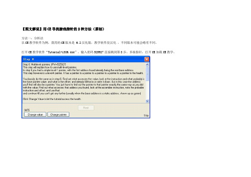
【图文解说】用CE寻找游戏指针的2种方法(原创)方法一:分析法以CE教学软件为例,我用的CE版本是 6.2汉化版,教学软件没汉化,不同版本可能会略有不同。
打开CE教学软件“Tutorial-i386.exe”,输入密码525927直接跳到第8步,多级指针,打开CE加载CE教学。
输入教学软件上给出的数字进行搜索。
得到一个地址,黑色的,说明是动态地址。
所谓动态地址,就是这个址是会变的,比如说在游戏中存放人物血的数值的地址,每次变换角色或者重新登录甚至变换一下场景,都会发生变化。
那么,通过读写这个地址来得到人物的血量值,就无法实现,变一下就找不到了。
现在我们就是要来分析这个地址是怎么来的。
双击一下这个地址,添加到下面的地址栏,然后右键点击这个地址,“找出是什么改写了这个地址”按一下教学软件上的按键“Change Value”改变数值。
好了,出来一行代码,正是这行代码在改写这个地址里的数值。
双击这行,看详细信息,CE提示要寻找的指针可能是“d7780”我们点新的搜索,选中16进制,数值是“d7780”,结果出来了,还是黑色的。
同样的方法把它添加到下面地址栏,但现在起我们要“找出是什么访问了这个地址”重复这一步的操作,直到搜索到的地址是绿色的为止,绿色的地址,表示是基址,不再会发生变化。
现在回过来梳理一下这个过程,原来我们一开始找到的那个地址,是经过这4次变化得来的。
这个是基址,这里是用一个模块加偏移表示的。
我们在CE上,点“手工加入地址”,钩选“指针”,按“Add Offset”,添加成有4级偏移的指针,最底下方框中输入基址(模块名+偏移),逐级往上每次的偏移量。
好了,指针地址添加好了。
现在测试一下,按教学软件上的“Change pointer”改变指针,看一下我们分析出来的这个指针是不是准确同步变化。
同时也可以看到,改变指针以后,前面找出来的那些动态地址,全都没用了。
上面,简要说了用分析法查找多级指针的方法,说得比较粗略,网上类似的教程也较多,大家可以去找找参考一下。
CE教材_商务900句

第七课:初次会面(上)
61 你好,我系飞翔外贸代理部嘅副经理,姓黄,呢张系我嘅咭片,请多多关照! 62 你好,我系客户经理,姓何,啱有啲嘢要处理,要你等咁耐,真系唔好意思。请坐,唔 知小姐贵姓咧? 63 你好,何小姐,我系广本嘅销售部经理,姓周,我唔好意思就真,唔阻你做嘢啊嘛? 64 唔好噉讲,多谢你哋一路以嚟都咁关照我哋。唔知我哋今次会合作啲咩货单呢? 65 今日嚟主要想倾下彼此合作嘅一啲细节问题。 你都知啦, 有啲嘢都系要大家坐埋慢慢倾 先至清楚架。 66 你讲得好啱,做生意系要噉嘅,三口六面全部倾掂佢,费事到时大家都唔好意思。 67 你第一次嚟我哋公司,如果唔介意嘅话,我带你四围行下咧,顺便请你指导下我哋嘅工 作。 68 唔好噉讲, 大家交流下嗻。 你哋公司嘅管理都几人性化啊, 呢方面系好值得我哋学习嘅! 69 点同得你哋比咧?你哋间公司嘅绿化好过我哋多多声啦。 呢方面我哋真系要向你哋好好 学习。
第十二课:希望与要求(下)
111 呢批货可能要船运先得,用货车嘅话,啲水晶大吊灯容乜易撞碎晒吖。 112 唔好意思吖!我哋想将之前订嘅果 3000 条方型抽纱枱布全部做返圆型吖,布料同啲色 都唔变,唔知有冇问题呢? 113 唔系唔得,不过星期一交货就赶唔切个,最快都要过一个星期至得。 114 至紧要嘅都系质量,迟果两日交货都唔系咩问题嗻。 115 我哋公司近排资金周转遇着啲问题,所以想同你哋银行贷住 200 万款先。 116 我哋银行会对你哋公司嘅财务状况先做一个详细嘅评估,然之后先至决定究竟批唔批畀 你哋。 117 你哋批货足足迟咗四日先到,搞到都唔知点同个客交待。希望唔好再发生噉嘅事。 118 希望你哋尽快搞掂赔偿方面嘅问题。 119 希望能够圆满解决今次嘅问题,大家都仲系想要继续合作嘅。 120 第一次拍档做嘢就咁顺,希望以后能够多啲合作。
汉语拼音字母写法顺序

汉语拼音字母写法顺序汉语拼音字母写法顺序汉语拼音采用拉丁字母和一些附加符号表示汉语的发音。
对应汉语音系学(现代音韵学)的汉语音节结构划分,汉语拼音的形式构成也分为声母、韵母和声调三部分。
下面是小编精心为大家整理的26个拼音字母表,欢迎阅读。
26个拼音字母表汉语拼音字母:Aa Bb Cc Dd Ee Ff Gg Hh Ii Jj Kk Ll Mm Nn Oo pp Qq Rr Ss Tt Uu Vv Ww Xx Yy Zz汉语拼音声母:b [玻] p [坡] m [摸] f [佛] d [得] t [特] n [讷] l [勒] g [哥] k [科] h [喝] j [基] q [欺] x [希] z [资] c[;雌] s [思] r [日] zh[知] ch [嗤] sh [诗] y [医] w [巫]汉语拼音韵母:单韵母 a[阿] o[喔] e[鹅] i[衣] u[乌] ü[迂]复韵母 ai[哀] ei[唉] ui[威] ao[奥] ou[欧] iu[由] ie[耶] üe[椰] er[儿] 前鼻韵母 an[安] en[恩] in[因] un[温]后鼻韵母 ang[昂] eng[摁] ing[英] ong[雍]整体认读音节:zi ci si zhi chi shi ri yi wu yu yin ying yun ye yue yuan声调符号:阴平:- 阳平:/ 上声:∨ 去声:﹨汉语拼音采用拉丁字母和一些附加符号表示汉语的发音。
对应汉语音系学(现代音韵学)的汉语音节结构划分,汉语拼音的形式构成也分为声母、韵母和声调三部分。
根据汉语拼音方案《字母表》的规定,汉语拼音使用26个现代基本拉丁字母,有大小写之分,字母顺序与英语字母表一致。
其中字母V/v,在方案中规定为“拼写外来语、少数民族语言和方言”之用。
由于汉语拼音的实际职能仅限于拼写汉语普通话,如今这条规定已然无人问津。
毛细管电泳的基本原理及应用
毛细管电泳的基来源根基理及利用之杨若古兰创作摘要:毛细管电泳法是以弹性石英毛细管为分离通道,以高压直流电场为驱动力,根据样品中各组分之间淌度和分配行为上的差别而实现分离的电泳分离分析方法.该技术可分析的成分小至无机离子、大至生物大分子如蛋白质、核酸等.可用于分析多种体液样本如血清或血浆、尿、脑脊液及唾液等,比HPLC分析高效、快速、微量.关键词:毛细管电泳道理分离模式利用1概述毛细管电泳 (Caillary Electrophoresis)简称 CE,是一类以毛细管为分离通道,以高压直流场为驱动力的新型液相分离分析技术.CE 的历史可以追溯到1967年瑞典Hjerten最早提出在直径为3mm 的毛细管中做自在溶液的区带电泳(Capillary Zone Electro-phoresis,CZE).但他没有完整克服传统电泳的弊病[1].此刻所说的毛细管电泳(CE)是由Jorgenson和Lukacs在1981年首先提出,他们使用了75mm的毛细管柱,用荧光检测器对多种组分实现了分离.1984年Terabe将胶束引入毛细管电泳,开创了毛细管电泳的次要分支: 胶束电动毛细管色谱(MEKC).1987年Hjerten等把传统的等电聚焦过程转移到毛细管内进行.同年,Cohen 发表了毛细管凝胶电泳的工作.近年来,将液相色谱的固定相引入毛细管电泳中,又发展了电色谱,扩大了电泳的利用范围.毛细管电泳和高效液相色谱(HPLC)一样,同是液相分离技术,是以在很大程度上HPCE与HPLC可以互为弥补,但是不管从效力、速度、样品用量和成本来说,毛细管电泳都显示了必定的上风毛细管电泳(C E)除了比其它色谱分离分析方法具无效力更高、速度更快、样品和试剂耗量更少、利用面同样广泛等长处外,其仪器结构也比高效液相色谱(HPLC)简单.C E只需高压直流电源、进样安装、毛细管和检测器.毛细管电泳具有分析速度快、分离效力高、试验成本低、耗费少、操纵简便等特点,是以广泛利用于分子生物学、医学、药学、材料学和与化学有关的化工、环保、食品、饮料等各个领域[2].2毛细管电泳的设备和基来源根基理毛细管电泳法是以弹性石英毛细管为分离通道,以高压直流电场为驱动力,根据样品中各组分之间淌度和分配行为上的差别而实现分离的电泳分离分析方法[3].毛细管电泳仪的基本构成如图1、1 所示 .熔融石英毛细管的两端分别浸在含有电解缓冲液的贮液瓶中,毛细管内也充满同样的电解缓冲液.在毛细管接收端之前安装在线检测零碎.被分析样品可以从进样零碎采取重力法、电迁移法、抽真空法等多种进样方式引入到毛细管的进样端.当样品被引入后,便开始在毛细管两端施加电压 .样品溶液中溶质的带电组分在电场的感化下根据各自的荷质比向检测零碎方向定向迁移.CE中的毛细管目前大多是石英材料.当石英毛细管中充入pH值大于 3的电解质溶液时 ,管壁的硅羟基(- SiOH)便部分解离成硅羟基负离子(- SiO-) ,使管壁带负电荷.在静电引力下 ,- SiO-会把电解质溶液中的阳离子吸引到管壁附近,并在必定距离内构成阳离子绝对过剩的扩散双电层 (见图 2[4]).在外电场感化下 ,上述阳离子会向阴极挪动.因为这些阳离籽实际上是溶剂化的(水化的),它们将带着毛细管中的液体一路向阴极挪动,这就是 CE中的电渗流(EOF).电渗流的强度很高,乃至于所有进入毛细管中的样品,不管是阴离子、阳离子或中性分子,都会随着液体向阴极挪动.因待测样品中正离子的电泳方向与电渗流方向分歧,故最早到达毛细管的阴极端;中性粒子的电泳速度为零 ,迁移速度与电渗流速度相当;而负离子的电泳方向则与电渗流方向相反,但因电渗流速度约等于普通离子电泳速度的 5~7倍[5],故负离子也将在中性粒子以后到达毛细管的阴极端.因为各种粒子在毛细管内的迁移速度纷歧致,因此使各种粒子在毛细管内能够达到很好的分离.3 毛细管电泳的分离模式根据分离道理分歧,CE分离基本模式有6种,如表 1 所示.表 1 毛细管电泳的分离模式和利用Tab. 1 Separation modes and application of CE以上各模式以毛细管区带电泳、毛细管凝胶电泳、胶束电动毛细管色谱这3种利用较多.4 毛细管电泳的利用4.1 CE在药物成分分析中的利用目前,CE在天然中草药分析领域中的利用次要集中在生物碱和黄酮及其甙类方面、蒽醌类分析也有报导.生物碱有类似于碱的性质,在pH < 7的缓冲液中利用 CZE 分离.纪秀红等[6]拔取马钱子碱为内标物,在磷酸/甲醇缓冲溶液中 ,测定了小檗碱、巴马亭、药根碱的含量.黄酮类化合物大多是中性分子,次要采取 MECC 模式分离.LiYM[7]以SDS(十六烷基磺酸钠)为阴离子概况活性剂将黄芩中的 6 种次要的黄酮类化合物分离.李伟等[8]以磷酸盐为缓冲体系 ,利用 CZE模式分离、测定了大黄提取液中离蒽醌化合物的含量.4. 2 CE在手性拆分中的利用CE因其高效、快速、选择性强的特点而成为目前最无效的手性拆分方法.各种CE分离模式皆可用于对映异构体分离,是以手性拆分成为 CE利用最活跃、最独特的领域.其中,添加剂法只需向电泳缓冲液中加入合适的手性试剂,经过必定的分离条件优化即能实现手性分离.又因为可选择的添加剂品种很多,此法是 CE进行手性拆分的次要方式.目前 ,次要的手性添加剂有环糊精类(CDs)、冠醚类、大环抗生素、蛋白质等.仅环糊精一类就有α-CD,β-CD,γ-CD,HP-α-CD, CM-β-CD 等多种添加物资 ,其利用十分广泛.此外,其他品种添加剂的利用结合MECC和 NACE 模式基本上能实现各种手性药物的拆分[9~11]. 4.3 CE用于肽和蛋白分析CE在蛋白质分离分析中的利用次要包含肽和蛋白的鉴别分析、结构分析、微量制备,蛋白的定量测定、纯度检测、非均一性检测、定性和动力学研讨.CE在肽和蛋白质的别分析中利用最多的是CZE测定肽谱, SDS-CGE测蛋白分子量及CE-MS 直接测定分子量.用CZE还可测定蛋白的物理参数,如蛋白的无效尺寸、电荷和扩散系数.用CIEF测定蛋白等电点比平板凝胶电泳测等电点的方法简单,可直接监测.蛋白被酶解或化学裂解成肽片断,利用CZE的高分辨率分离后所得的电泳图称CE肽图.肽图是进行蛋白序列分析的第一步,随后可用CE进行微量制备,再测定各片断的氨基酸序列,即可得出全部蛋白的一级结构.CE的制备总量比高效液相色谱低,只适用于微量制备.对扩散系数小的生物大分子而言,CE比HPLC的分辨率高得多,是以CE被用来作为收集非常纯的单一馏份的微量制备的手段.在有些情况下,CE定量线性范围可达(3个数量级).4.4 CE用于糖类的分析近年来,毛细管电泳已成为分析单糖、寡糖、糖肽、糖蛋白等糖类化合物的无力兵器,在糖型分析.方面也取得了较大的成功单糖的pKa6值普通大于11,故需选用强碱性的缓冲液(pH>11),使糖基上的羟基去质子而带负电荷,直接进行电泳分离,用紫外(195nm)检测.也能够选用硼酸盐缓冲液,硼酸盐与糖基络合构成带负电荷的络合物以进行电泳分离,用紫外检测.简单单糖的分析方法也适于简单寡糖的分析[12].多糖普通利用酸解或酶解的方法将其转化为寡糖后进行分析.糖蛋白经蛋白酶酶解后生成糖肽,糖肽的图谱被认为是糖蛋白的指纹图谱.糖肽的分离主如果基于其pKa值的分歧而进行CE分离,其实不是基于糖链结构的分歧,是以所选用的缓冲液的构成及其pH的选择尤其次要,其检测也是基于蛋白质的检测.糖脂既可以直接用CE分离,也能够用神经酰胺聚糖酶将糖链释放出来后进行分析.糖胺聚糖(GAG)类糖基的聚糖部分有透明质酸、硫酸软骨素、硫酸角质素和肝素等,普通都含有反复的二糖单元,而且可用裂解酶降解成糖醛酸化酸性寡糖,这些寡糖既带电荷又有紫外接收(232nm),是以很适合用CE进行分析.另外,CE在糖型分析方面也取得了较大的成功.在糖的检测方面,紫外分析是最早用于CE进行糖类检测的,但它的灵敏度绝对不高,检出限普通只要10—6mol数量级.利用激光引诱荧光检测对糖类进行柱前高效荧光标识表记标帜,可使检出限达到10-9mol水平.在改进检测零碎的同时,中性糖类的极性标识表记标帜也在不竭改进与完美.其中一种极性标识表记标帜物为8-氨基-萘-1,3,6-三磺酸,利用其可以快速高效地对均一寡糖和复杂多糖进行分离分析,具有很高的分辨率.4.5 CE在临床化学上的利用CE 在临床化学中的利用十分广泛, 所检测样品的来源可分为尿样、血浆血清、脑脊液、红细胞、其它体液或组织和实验动物活体(invivo)试验.被分析的组分则包含肽类、各种蛋白、病毒、酶、糖类、寡核苷酸、DNA、小的生物活性分子、离子、药物及其代谢产品.具体利用可分为: 临床疾病诊断临床蛋白分析、临床药物监测、代谢研讨、病理研讨、同工酶分析、聚合酶链反应(PCR )产品分析、DNA 片断及序列分析等.所利用的CE 模式包含CZE、MECC、CGE、 CITP 和毛细管等电聚焦(CIEF)[13.14].4.6 CE用于检测非均一性(多样性, Heterogeneity)很多纯化蛋白, 甚至在它们的天然形态, 常常都不是单一分子片断, 而是由相干分子构成, 称为非均一性(多样性).发生多样性的缘由有: 氨基酸(AA )的序列分歧, 如突变体的某地位AA 改变或AA 侧链改变; 后转译发生分歧长度的多肽链; 糖蛋白分歧程度的糖基化, 如存在分歧数量的寡糖链, 寡糖链有分歧的单糖构成、序列及单糖之间的异构连接. 采取CZE, MECC, CIEF, CE-MS 可检测这些非均一性.用于心脏病的重组人组织血纤维蛋白溶酶原激活剂(rtPA )含 4 个可能糖基.Yim [15]用 CZE 和CIEF 研讨了制备过程中 rtPA 分歧糖基化程度惹起的非均一性, 结果标明, CIEF方法要比CZE的好.还有效CZE 对人促红细胞生成素( rHuEPO )[16]、用MECC对重组人C2干扰素(IFN2C)[17]及CE-MS[18]研讨蛋白的多样性.有关蛋白的非均一性在临床中的一些利用, 如人铁传递蛋白、血清蛋白的变异、异构酶的分析等.4. 7 CE用于农药残留量的分析对农药残留物的测定国外研讨的较多.Lazer等[19]将飞行时间质谱和毛细管电泳仪联用,采取样品堆积技术进样对 Paraquat 和 Diquat 两种除草剂进行了分离,检测限低至 10- 17mol/L.Farran 等[20]采取φ(乙腈) = 50 %的磷酸-硼砂缓冲液分离出两种苯氧羧酸类除草剂.Hinsmann 等[21]通过主动在线浓缩样品,采取固相微柱以十二烷基硫酸钠(SDS)作胶束 ,添加少量乙腈 ,在13min内分离测定了水中的7种分歧品种的农药.磺酰脲类化合物是一类绝对较新的除草剂,是以这一类化合物在水和食品中的残留量的测定十分次要.Lipez Avila等[22]采取3μmODS硅胶填充柱来分离这一类化合物 ,线性范围为1~100mg/L.Mayer等报导了农药Cinosulfuron 及其副产品的毛细管电色谱的分离分析.游静等[23]对毛细管电泳在农药手性拆分的进展做了综述.4.8 CE用于纯度检测CE在国外分子生物学实验室及生物工程药厂里已广泛用作最无效的纯度检测手段.当蛋白的疏水性附近时, 它们在HPLC 柱中常常同时流出, 是以在对蛋白进行结构研讨(包含N 端序列和肽谱)之前, 必须监测从HPLC 所得肽片断的纯度.快速CE 纯度检测可节约样品和节省序列测定所需时间.因CE 和RP2 HPLC 分离机理分歧, 所以当用CE 检查由RP2HPLC 纯化制得的某一合成肽(一个峰, 纯度为 99.12% )时, 发现分出 6 个组分, 主峰纯度仅为50%.或许这就是部分基因工程产品用HPLC 检测纯度很高而实际生物活性却各批差别很大的一个缘由.至于用CE 对药厂生产及QC 作纯度检测的利用实例触目皆是, 如对胰岛素、白细胞介素、人生长激素、粒性巨噬细胞菌落刺激因子(用CIEF )等的检测.纯度检测时用CE 可检测出多肽链上单个氨基酸的差别.CE 用于纯度检测可用CZE,MECC, SDS2 CGE, CIEF 多种模式.还有文献讨论了用分歧方法(包含RP2 HPLC, IEC2 HPLC, SDS2PA GE 及CE)进行纯度检测的最无效的计谋[24].5 结论作为一种蛋白质、多肽、核酸及其他生物分子分离和分析的次要技术,近20年来,毛细管电泳的机理探索和利用研讨都取得了长足的进展,对毛细管电泳的研讨,使其分离效力和分析精度不竭提高,也使其利用领域不竭扩大,推动了生物技术的不竭发展.毛细管电泳今后发展方向仍是继续提高分辨率、速度和检测器的选择性.同时,添加主动进样安装和使之微机化、商品化.另外,将它与质谱仪更好地结合,可对生物分子特性作出更快、更精确的分析,以进一步拓宽毛细管电泳在生物领域的利用范围.。
网络产品CEAS文档制作指导书_V0[1].9_20100401_B
![网络产品CEAS文档制作指导书_V0[1].9_20100401_B](https://img.taocdn.com/s3/m/a3b0a04e852458fb770b5661.png)
网络产品CEAS文档制作指导 1 前言目录1 前言............................................................................................................................................... 1-22 CEAS文档规范要求.................................................................................................................... 2-13 接入网产品CEAS文档制作...................................................................................................... 3-33.1 接入网CEAS脚本采集.............................................................................................................................. 3-33.1.1 使用CEAS脚本生成工具批量采集网元CEAS脚本..................................................................... 3-43.1.2 使用iManager N2000 BMS 网管采集接入网元CEAS脚本 ......................................................... 3-93.1.3 使用iManager U2000导出工程文档.............................................................................................. 3-183.2 利用脱机工具导入脚本文件.................................................................................................................... 3-203.2.1 脱机工具导入脚本的准备工作....................................................................................................... 3-203.2.2 操作步骤 .......................................................................................................................................... 3-213.3 客户设备档案其它信息的填写................................................................................................................ 3-263.3.1 填写档案信息、档案附件添加并导入个人信息........................................................................... 3-263.3.2 网元清单的引入............................................................................................................................... 3-293.3.3 数据采集文件的添加....................................................................................................................... 3-313.3.4 合同号、工程号的填写................................................................................................................... 3-313.3.5 完整性检查....................................................................................................................................... 3-323.3.6 档案上载 .......................................................................................................................................... 3-334 数通产品CEAS文档制作.......................................................................................................... 4-14.1 数通CEAS脚本采集.................................................................................................................................. 4-14.1.1 使用质量检查工具采集网元CEAS脚本......................................................................................... 4-24.1.2 使用iManager U2000导出工程文档................................................................................................ 4-84.2 利用脱机工具导入脚本文件...................................................................................................................... 4-94.3 客户设备档案其他信息的填写................................................................................................................ 4-105 传送网产品CEAS文档制作...................................................................................................... 5-15.1 传送网CEAS脚本采集.............................................................................................................................. 5-15.1.1 使用Optix iManager T2000网管采集传送网元CEAS脚本 .......................................................... 5-25.1.2 使用iManager U2000导出工程文档................................................................................................ 5-65.2 利用脱机工具导入脚本文件...................................................................................................................... 5-65.3 客户设备档案其他信息的填写.................................................................................................................. 5-86 审批、归档状态跟踪 .................................................................................................................. 6-16.1 文档质量标准.............................................................................................................................................. 6-16.2 工程文档管理员清单.................................................................................................................................. 6-27 CEAS文档信息维护与更新........................................................................................................ 7-47.1 档案合并...................................................................................................................................................... 7-47.1.1 脱机检出 ............................................................................................................................................ 7-47.1.2 档案合并 ............................................................................................................................................ 7-61 前言网络产品CEAS文档制作指导7.2 联机修改文档.............................................................................................................................................. 7-67.2.1 进入联机维护模式............................................................................................................................. 7-77.2.2 修改主机版本..................................................................................................................................... 7-87.2.3 单板删除 ............................................................................................................................................ 7-97.2.4 单板新建 .......................................................................................................................................... 7-107.2.5 单板的更换....................................................................................................................................... 7-127.2.6 网元退网 .......................................................................................................................................... 7-127.2.7 联机检入 .......................................................................................................................................... 7-137.3 批量更新工程文档中的网元信息 ............................................................................................................ 7-158 FAQ ............................................................................................................................................. 8-161 前言此文档目的是指导华为工程师及华为合作方工程师完成在工程验收期间工程文档制作及维护期间工程文档信息的维护。
AACE软件安装指导
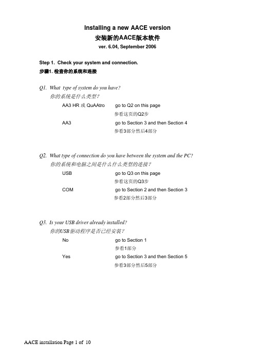
Installing a new AACE version安装新的AACE版本软件ver. 6.04, September 2006Step 1. Check your system and connection.步骤1. 检查你的系统和连接Q1. What type of system do you have?你的系统是什么类型?AA3 HR 或 QuAAtro go to Q2 on this page参看这页的Q2步AA3 go to Section 3 and then Section 4参看3部分然后4部分Q2. What type of connection do you have between the system and the PC?你的系统和电脑之间是什么什么类型的连接?USB go to Q3 on this page参看这页的Q3步COM go to Section 2 and then Section 3参看2部分然后3部分Q3. Is your USB driver already installed?你的USB驱动程序是否已经安装?No go to Section 1参看1部分Yes go to Section 3 and then Section 5参看3部分然后5部分1. USB驱动的安装 USB Driver Installation- Put the Original AACE CD in the disk drive of your computer.将AACE CD光盘放入你的电脑的光盘驱动器中。
-If the automatic installation tool comes up and wants to start the installation,interrupt it. First you have to install the USB drivers.如果自动安装工具出现并要开始安装进程,中断它。
ce傻瓜教程、菜鸟都会

ce傻瓜教程、菜鸟都会CE游戏修改器制作游戏修改器傻瓜教程出处:西西整理作者:西西人气:10874傻瓜教程目标是:注重操作,不求深入,主要是为了培养各位的兴趣和带你迅速入门。
先简单介绍下什么叫CE,CE的全称是Cheat Engine,最新的版本是5.6.1(作者是Dark Byte)CE是目前最优秀的游戏修改器,不是之一,这个工具绝对值得你去学习(只要花一点时间就够了)。
忘记金山游侠,GM8,FPE之类的修改工具的吧,CE会让你爱不释手。
一、先下载CE 5.6.1,这个汉化版相当不错哦(不需要安装),推荐各位下载使用。
下载地址:/soft/23578.html二、打开CE目录下的2个文件:三、附加进程(图示):操作到此就结束了。
这个教程就是如此简单,下一关同样如此。
(就像玩游戏一样,完全是闯关试的操作,请各位按照顺序,一关一关的走)按下一步进入教程第二关,需要扫描的精确数值是100现在开始搜索精确数值100 数值中输入100点击首次扫描按钮一般游戏就是4字节,这里不需要改动,默认就好。
这次扫描我们得到59 个结果,里面肯定有我们要找的那个血值,不过好像太多了。
关键一步:回到Tutorial 点击打我按钮,此时血值已有变化了:我们再输入96 点击再次扫描按钮结果只剩1个(这就是我们要找的),我们双击此地址将其添加到地址栏:只有1个结果了,这个就是我们要找的内存地址,双击将其加入到地址栏图示操作:把95 改成1000 点击确定按钮此时教程的下一步按钮变成可用闯关成功。
操作虽然简单,但是大家需要明白这其实是一个筛选的过程,这样操作就能把地址找出来。
本关的小技巧:1、双击下图对应位置可快速更改数值。
2、双击地址可快速将其加入到地址栏第3关的密码是419482这一关很重要,因为某些游戏中血显示的不是数字而是血条,这样的话教程2中的方法就失效了。
本关就你要教会你如何修改这些讨厌的未知数此时点击新扫描然后选择未知初始数值点击首次扫描然后出现了肯定是N多的结果,因为太多了,CE没有显示出来。
CE傻瓜教程七:代码注入11页
第七关的密码是 013370从本关开始,各位会初步接触到CE的反汇编功能,这也是CE最强大的功能之一。
在第6关的时候我们说到指针的找法,用基址定位动态地址。
但这一关不用指针也可以进行修改,即使对方是动态地址,且功能更加强大。
看看教程让我们做什么:原来每按一次按钮减少1点血,改成每按一次按钮增加2点血。
还记得第5关的不伤血的修改方法吗?这一关就是第5关的加强版。
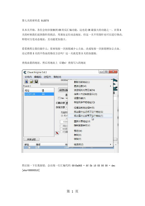
查找血量的地址,然后再地址上右键=> 查找写入的地址然后按一下打我按钮,会出现一行汇编代码 0045a063 - ff 8b 10 03 00 00 - dec[ebx+00000310]双击那行代码,看下详细信息:这行代码什么意思呢?dec 大家都知道是英文减少的意思图示红框处:EBX=01e0ee18我们用计算器算一下(注意是16进制的)01e0ee18 + 310 = 01E0F128正好是血量的地址。
dec [ebx+00000310] = dec [01E0F128] 够清楚了吧,这就是让血量减1的代码(1省略了),其实CE中也有提示 Decrement by 1 。
明白了这行代码的意思,我们回去看看Tutorial的要求:把减1改成加2。
继续操作。
选择反汇编程序点击工具,选择自动汇编第一步选择作弊框架代码第二步选择代码注入对应的地址不要搞错了,是0045A063然后按确定,会自动生成汇编代码,这些代码是什么意思,我们先不管,找到关键的一行:dec [ebx+00000310]把代码注释掉(删除也行),改成 add [ebx+00000310],2保存即可,然后在地址栏就可以看到这个脚本了,点击前面的单选框执行,然后点击Tutorial中的打我,这关就可以过了。
你感觉到他的神奇了吗?逆天级的修改:1、怪物每次打我从伤血变成加血。
2、子弹越打越多。
3、钱越花越多。
如果你学会了这一关,你已经脱离菜鸟的行列了,不要再提金山游侠,FPE,GM8之类的修改工具了,告诉你们的朋友快来学习CE吧。
CE认证的基本内容

CE认证的基本内容CE认证CE认证,即只限于产品不危及人类、动物和货品的安全方面的基本安全要求,而不是一般质量要求,协调指令只规定主要要求,一般指令要求是标准的任务。
因此准确的含义是:CE标志是安全合格标志而非质量合格标志。
是构成欧洲指令核心的"主要要求"。
“CE”标志是一种安全认证标志,被视为制造商打开并进入欧洲市场的护照。
CE代表欧洲统一(CONFORMITE EUROPEENNE)。
在欧盟市场“CE”标志属强制性认证标志,不论是欧盟内部企业生产的产品,还是其他国家生产的产品,要想在欧盟市场上自由流通,就必须加贴“CE”标志,以表明产品符合欧盟《技术协调与标准化新方法》指令的基本要求。
这是欧盟法律对产品提出的一种强制性要求。
中文名:CE认证外文名:CE certification含义:安全合格标志而非质量合格标志。
目的:证明通过国际安全标准测试词义起源:CE是法语的缩写,英文意思为“European Conformity 即欧洲共同体,事实上,CE还是欧共体许多国家语种中的"欧共体"这一词组的缩写,原来用英语词组EUROPEAN COMMUNITY 缩写为EC,后因欧共体在法文是COMMUNATE EUROPEIA,意大利文为COMUNITA EUROPEA,葡萄牙文为COMUNIDADE EUROPEIA,西班牙文为COMUNIDADE EUROPE等,故改EC为CE。
当然,也不妨把CE视为CONFORMITY WITH EUROPEAN (DEMAND)(符合欧洲(要求)),构成欧洲指令核心的"主要要求",在欧共体1985年5月7日的(85/C136/01)号《技术协调与标准的新方法的决议》中对需要作为制定和实施指令目的"主要要求"有特定的含义,即只限于产品不危及人类、动物和货品的安全方面的基本安全要求,而不是一般质量要求,协调指令只规定主要要求,一般指令要求是标准的任务。
- 1、下载文档前请自行甄别文档内容的完整性,平台不提供额外的编辑、内容补充、找答案等附加服务。
- 2、"仅部分预览"的文档,不可在线预览部分如存在完整性等问题,可反馈申请退款(可完整预览的文档不适用该条件!)。
- 3、如文档侵犯您的权益,请联系客服反馈,我们会尽快为您处理(人工客服工作时间:9:00-18:30)。
此文很适合AA入门,看上去很长,但作者一直用一种比较诙谐的讲述方式,读下来并不难,而且本文的内容一点都不难。
本人英语渣,出现误译及错别字请多包涵。
原文地址:/viewtopic.php?t=95363
EAX: 累加器(Acculmulator register)。能够用来当存储器
EBX: 从前, 它是个基础寄存器,但现在只是个闲着的存储器
ECX: 计数器(Counting register)。也能用来当存储器
EDX: 数据寄存器(Data register)。 跟之前三个一样,能用来当存储器。
II. 寄存器
------------------------------
这些也许你已经在一些脚本中看到过,它们被非常广泛的使用。有两种寄存器被使用,接下来来进行讲解。
---------------
II.a 32 Bit
---------------
首先,我将解释每个寄存器是如何得到它们的名字的,这会帮助你记住它们哪个是哪个。首先,以E开头 (如果你注意了下面,你会发现所有的寄存器都是以E开头的) 它告诉你这个寄存器是32位寄存器。而A,B,C,D的含义你看完描述就能明显得体会到了。像SI, DI, BP,SP,IP也是一样。在 EAX, EBX, ECX, EDX后面的X,他简单的表示已经没有更多的字母了。有点像一个 NOP 命令 (之后你将读到)。如果你注意了,你会发现每个32位寄存器都是3个字母。
这个的意思是把ebx里面的值存到eax所存的地址里,很简单, 把寄存器或者地址用[]那么一括,就表示寄存器或者地址的值了。
下面这段代码什么效果都没有。
Code:
mov [eax],[ebx]
没效果,上面的代码啥用没有。你不能!你不能直接把一个值存在另一个值里面。你可以间接得先把值存在其他的东西里 ;) 参考下面的代码。
ESP: 原址指针寄存器(Source Pointer register)。它在堆栈里指向寄存器和地址(这个内容待会再说)。
EIP: 指令指针寄存器(Instruction Pointer register)。 错误的使用会使你正在试图修改的程序崩溃。
---------------
II.b 16 Bit
pop eax //然后让eax出栈,这个也待会讲
解释这个是为了MOV函数。继续...
本帖最后由 cn_zou 于 2011-1-8 14:20 编辑
---------------
III.c Push and Pop + The Stack
Dark Byte wrote:
大多数人都认为AA很难,其实它可容易了。
来自CE作者自己的话
如果是后者,那我不会给你提任何的建议,即使我想帮忙。如果你发现有什么错了,或者含糊或者认为我可以做的更好,请告诉我。我一直处于自我学习的状态! 等等!别问,我知道你在想什么。
You wrote:
---------------
你已经看了上面的Push和Pop 命令的用法。等等!我是尤里!我能读你的思想!
You wrote:
那个push和pop都是干啥的?还有啥是stack?
好,你读了前文, 在"Push"之后,我是这么注释的。
Code:
为什么我非要听一个还在学习的人的话?
好,我来告诉你,我的朋友。即使我仍然在学习,我了解AA,并且我认为与你分享知识是一件很棒的事。 =)
Edit: 这个是很久以前写的,但是现在我学到了很多,并且已经重新检查了。
现在,让我们投身入奇幻的电脑世界
------------------------------
JNL: 有符号不小于则跳转(Jump to if not Lower)
JAE: 无符号大于等于则跳转(Jump to if Above or Equal)
JGE: 有符号大于等于则跳转(Jump to if Greater orEqual)
JNAE: 无符号不大于等于则跳转(Jump to if not Above orEqual (即 JB) )
JNGE: 有符号不大于等于则跳转(Jump to if not greaterthan or Equal (即JL) )
现在你大致了解了,应该有些疑惑。 "Jump to if greater"或者JG都是条件跳转。 条件跳转都如同它们名字所描述的那样,会在条件成立的情况下跳转。通常,都会有CMP或者其他的比较函数在上面,这个待会再提。以上大抵就是JMP的故事。
III. 命令
------------------------------
当今,什么语言没有它自己的函数和命令呢? 与英文相比,命令像个单词,而操作代码像个句子。操作代码并不难,比如:
Code:
jmp 00123EAA
关于操作代码你应该知道两点。
首先, 在操作码里,一般都会有个地址或者寄存器,以及一个显而易见的命令。地址是Hex形式的,是Hexadecimal的缩写。Hexadecimal是16进制数。 就如同10进制那样。
按照这种思路想一想。如同上面提到的那样,我们一般使用十进制。这就意味着我们在一个列里不能有“10”, 因为它占了两个地方。 而16进制,10至15都可以放在一个列里头。但是你会发现,“10”并没有出现在列里头。
先冷静, 这是因为在Hex进制里,10是用A表示的,而11是用B,直到15是F。再往后,它就是10,然后11,直到1F, 如果超过了20(十进制)就得从15(十六进制)往后算。有个简单的转换方法就是用操作系统自带的计算器,这里不赘述了。
I. 介绍
------------------------------
'哟,我猜你在读这个是因为下面两件事中的一个。
1) 你正在试图学习自动汇编 (我不会叫你菜鸟,因为每个人都是从哪里开始的,对吧 =) )
or
2) 你想测试你的自动汇编知识 (作为扩展)。
那么,如果你是前者,那就慢慢的体会好每个部分,并且在继续进行前确认自己已经明白了这章。
JNA: 无符号不大于则跳转(Jump to if not Above)
JNG: 有符号不大于则跳转(Jump to if not Greater)
JB: 无符号小于则跳转(Jump to if Below)
JL: 有符号小于则跳转(Jump to if Lower)
JNB: 无符号不小于则跳转(Jump to if not Below)
Code:
push eax //先让eax入栈—这个待会解释
mov eax,[0100200A] //把值0100200A存到eax里
mov [ebx],eax //把(值0100200A) 存到ebx的值里面
ESI: 源址变址寄存器(SourceIndex register)。 是字符串形式的指针变量,但你现在还不用担心那部分。 能够用来当存储器。
EDI: 目的变址寄存器(DestinyIndex register)。又一次,能够当作存储器,并且是个字符串形式的指针变量, 但别担心。
EBP: 机制指针寄存器(Base Pointer register)。 。
---------------
III.b MOV
---------------
前文已经提过, MOV 命令是最被广泛实用的命令,因为它是那么给力。 下面就是MOV的例子:
Code:
mov eax,ebx
这个的意思是 "把ebx里存的地址放到eax里"。注意在两个寄存器之间还有个逗号,而不是空格。 最开始这可能有些令人费解,但是它真的很容易,下面来好好解释一下。
---------------
16位寄存器和32位寄存器很相似,他们间有两个区别。一是,32位寄存器名字是三个字母,而16位寄存器是两个字母。还有一件事就是16位寄存器比32位寄存器多但别担心。16位寄存器我们一般都用不上。
AX: 参照 EAX
BX: 参照EBX
CX: 参照ECX
DX: 参照EDX
------------------------------
内容表
------------------------------
I. 介绍
II. 寄存器
II.a 32位寄存器
II.b 16位寄存器
III. 指令
III.a JMP
III.b MOV
III.c Push/Pop + The Stack
//Push eax onto the stack (让eax入栈)
这个基本上就是把eax存到堆栈里。而pop eax 基本上就是把eax从堆栈中清除。CEF的Skyone写了一个非常非常好的关于堆栈的解释,我甚至无法容忍自己不让你像我那样获得对此学习的快乐;)
Skyone wrote:
"Mov"是"move"的意思。 寄存器自身表示"这个寄存器里存的地址"。 基本上来说, "把ebx里存的地址放到eax的地址里面去", 这会把eax之前的值覆盖并彻底消灭掉。=D你可以通过这个方法复制ebx并把它粘贴到eax里。
另一种Mov命令。
Code:
mov eax,[ebx]
还有,每一个地址都有它的操作码和字节码。这个字节数就是代表操作码是什么, 每一个命令都一一对应已经定义好的字节码。我知道那些常用函数的字节码是什么,如果你想知道那些字节码的话,你还是指望别人吧,推荐去拜Google大神 =)
