VNXe3200详细安装配置文档
VNXe-系列-3200-硬件信息指南

VNXe3200 双 SP 平台最适合于具有物理服务器基础架构的企业,以及转向通过服务器 虚拟化来促进整合和提高效率的企业。VNXe3200 双 SP 平台还共享一组全面的功能,包 括极大的容量利用率、数据保护和可用性解决方案以及高级支持功能。
Removing these drives will make the array unusable
SPD
SAS 2TB
7.2K
Removing these drives will make the array unusable
SPD
SAS 2TB
7.2K
Removing these drives will make the array unusable
第 6 页上的 “VNXe3200 平台”
描述和显示典型 VNXe3200 双 SP 平台的前后视图。
第 9 页上的 “系统组件描述”
提供构成 VNXe3200 双 SP 平台的组件的描述。除了描 述以外,还显示每个组件的插图。
第 9 页上的 “磁盘处理器存储模块” 描述和说明 DPE 的前部和后部,以及构成 DPE 的组件。
关于本指南
关于本指南
本指南面向负责安装、配置和维护 VNXe3200 双 SP 平台的人员。要使用本硬件出版物, 您应熟悉数字存储设备和缆线连接。
重要
计算 VNXe3200 双 SP 平台的驱动器数量时, DPE 包括在最多 150 个驱动器的驱动器插 槽总量中。如果驱动器插槽总量超过 150,将无法添加其他 DAE。第 34 页中的 “磁盘 阵列存储模块”一节提供了有关 VNXe3200 双 SP 平台的可用 DAE 的更多信息,以及一 份配置表。
(完整版)JUNIPER_EX3200交换机配置
JUNIPER EX3200交换机配置1 Ex3200开机指导开机后:login: rootLast login: Fri Jan 17 22:21:55 on ttyd0--- JUNOS 7.2R3.3 built 2002-03-23 02:44:36 UTCTerminal type? [vt100] <enter>root@%注意使用root用户登录的情况下,输入帐号/密码以后,默认是进入shell模式的(而只有root用户帐号有这个现象),要输入cli命令进入用户模式:root@% cliroot>2 配置模式用户模式下输入configure命令进入配置模式,配置模式下可以对设备进行各种参数的配置root> configure[edit]root#2.1 设置root用户密码命令:set system root-authentication plain-text-password路由器初始化root用户是没有密码的,在第一次进行配置的时候必须要配置root密码才能commit成功。
密码采用字母+数字方式。
Example:lab@M7i_GZ# set system root-authentication plain-text-passwordNew password:Retype new password:2.2 添加系统用户命令:set system login user juniper uid 2000 <-设置用户名为juniper用户id为2000set system login user juniper class super-user <-设置juniper用户为超级用户set system login user juniper authentication plain-text-password <-设置juniper用户的密码2.3 设置主机名命令:set system host-name M7i_GZ <-设置主机名为M7i_GZ2.4 开启系统telnet服务命令:set system services telnet说明:系统默认是没有打开telnet功能的,只有打开telnet服务之后才能从网络上登陆到路由器。
VNXe3200
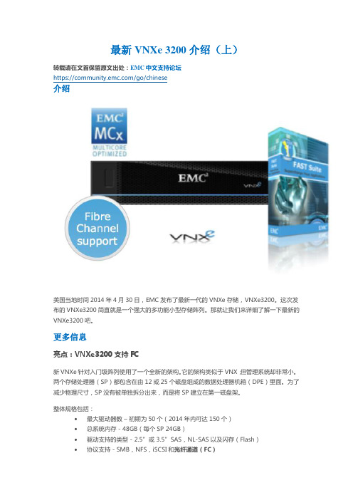
最新VNXe 3200介绍(上)转载请在文首保留原文出处:EMC中文支持论坛https:///go/chinese介绍美国当地时间2014年4月30日,EMC发布了最新一代的VNXe存储,VNXe3200。
这次发布的VNXe3200简直就是一个强大的多功能小型存储阵列。
那就让我们来详细了解一下最新的VNXe3200吧。
更多信息亮点:VNXe3200支持FC新VNXe针对入门级阵列使用了一个全新的架构。
它的架构类似于VNX,但管理系统却非常小。
两个存储处理器(SP)都包含在由12或25个磁盘组成的数据处理器机箱(DPE)里面。
为了减少物理尺寸,SP没有被单独拆分出来,而是将SP建立在第一磁盘架。
整体规格包括:∙最大驱动器数–初期为50个(2014年内可达150个)∙总系统内存 - 48GB(每个SP 24GB)∙驱动支持的类型 - 2.5”或 3.5”SAS,NL-SAS以及闪存(Flash)∙协议支持 - SMB,NFS,iSCSI和光纤通道(FC)物理端口 - 4个10GBase-T端口和4个8Gb光纤端口它运行MCx操作环境,就像当前的VNX。
这一点很重要,因为它拥有与VNX相同的多核性能增强,以及许多相同的功能,例如FAST VP。
软件功能的增强像当前的VNX一样,新VNXe的软件更新也非常显著。
MCx可以更好的利用新式的多核CPU,并拥有一些非常强大的软件功能。
相信之前是从未见过这种规模和价格的阵列。
FAST VPFAST VP(Fully Automated Storage Tiering Virtual Provisioning,全自动存储分层虚拟资源调配)可以允许你创建一个包含不同类型磁盘的池。
根据需要,在池中,阵列将“向上”或“向下”移动数据来加快(SSD)或减慢(NL-SAS)磁盘。
我们可以清楚的看到一个池由SSD,SAS和NL-SAS构成,并让阵列进行处理将数据放在正确的层。
VNXe320000实施文档
VNXe320000实施文档目录目录 (1)1、设备初始化 (2)2、Storage pool建立 (2)3、修改管理地址 (3)4、划分LUN空间 (3)5、建立虚拟NAS服务器以及文件系统 (4)6、LUN空间映射 (5)7、空间概览 (5)1、设备初始化作为统一式存储已经实现了后台初始化的功能,设备可以在配置完成后自主后台磁盘初始化并且不影响数据安全及设备正常使用。
2、Storage pool建立建立一个以24块NL-SAS盘为基础的R6 Pool(6+2),以磁盘及空间和安全综合考量,需要有一块可用磁盘做热备盘,目前VNXe3200支持自主的热备机制,设备默认没有建立Raid及Pool的所有磁盘均为热备盘所以不需要手动建立热备盘。
设备所建Pool为一个可用空间为71.1TB的Pool,Pool名为:storagepool00.3、修改管理地址设备默认管理地址为:192.168.1.10,NCS2600因为内部两台控制器已经做了连接通信,两台控制器共用一个IP地址,设备IP设置为:10.18.201.10,网关为:10.18.201.10,掩码为:255.255.255.0.4、划分LUN空间在存储——LUN中选择新建,分别建立Backup(16TB)、APP(8TB)两个Lun5、建立虚拟NAS服务器以及文件系统在设置选项中分别建立两台NAS服务器,同时在存储选项中新建两个8TB的文件系统,并且将文件系统映射给新建的虚拟NAS服务器。
6、LUN空间映射在存储选项中选择需要映射的LUN,点击详细信息,将LUN映射给需要看到的主机。
7、空间概览点击系统选项可以通过饼状图查看存储的总空间、使用空间以及剩余可划分的空间。
3200软件使用说明

点击 安装
第二章 软件使用说明
离线软件介绍
离线软件可以用来查 看上传的控制器参数, 了解和学习现场正在使 用的参数配置。 以大宇项目现场参数 2.系统的基本能及组成 为例,右图为现场上传 参数,可以双击打开现 场上传文件,就可以查 看里面的各个参数配置。
大宇发电机上传参数文件
双击打开 可查看现场所 用的配置参数
easYgen3200使用说明
目 录
软件安装说明
软件使用说明
简要功能说明
第一章 软件安装说明
该软件包括以下两个:
1.设备布置平面图
离线参数查看软件(右图Toolkit为安装包)
在线参数设置修改软件(右图configuration files为其安装包) 离线软件安装方法: 2.系统的基本能及组成 打开Toolkit文件夹,里面包含右图dotnetfx35安装 文件和toolkit文件,首先安装dotnetfx35,安装完 成后再点击安装toolkit,完成后离线软件就安装 成功了。在开始菜单中可以看到如 右图所示文件,平时只需双击上传 参数文件就可以打开离线参数。
按发电机负载 的参数设置
在config_CAN1配置 CAN BUS1的通讯设 置,其中我们需要关 注的是3156 Baudrate 波特率以及参数8950 Node_ID CAN bus 1 通讯地址。
Config_Controller里面的 load_share里面的1723 Segment 可以对母线上的发电机进行分断, 设置为2可通过12929里面的逻辑 进行使能。 例如:如右图II所示有6台发电机, 可以将1,2,3,4号发电机分为1 段,将5,6号发电机分为2段,可 以通过母联断路器B的信号来使能 2段,如果母联断路器合闸,那么 让设置2段不使能,6台发电机共母 排进行负载分享,如果母联不合闸, 那么1723设置为2时,通过12929 逻辑添加母联信号来使能2 段,1,2,3,4号发电机进行负载分享, 5,6号发电机进行负载分享。
JUNIPER EX3200交换机配置
JUNIPER EX3200交换机配置1 Ex3200开机指导开机后:login: rootLast login: Fri Jan 17 22:21:55 on ttyd0--- JUNOS 7.2R3.3 built 2002-03-23 02:44:36 UTCTerminal type? [vt100] <enter>root@%注意使用root用户登录的情况下,输入帐号/密码以后,默认是进入shell模式的(而只有root用户帐号有这个现象),要输入cli命令进入用户模式:root@% cliroot>2 配置模式用户模式下输入configure命令进入配置模式,配置模式下可以对设备进行各种参数的配置root> configure[edit]root#2.1 设置root用户密码命令:set system root-authentication plain-text-password路由器初始化root用户是没有密码的,在第一次进行配置的时候必须要配置root密码才能commit成功。
密码采用字母+数字方式。
Example:lab@M7i_GZ# set system root-authentication plain-text-passwordNew password:Retype new password:2.2 添加系统用户命令:set system login user juniper uid 2000 <-设置用户名为juniper用户id为2000set system login user juniper class super-user <-设置juniper用户为超级用户set system login user juniper authentication plain-text-password <-设置juniper用户的密码2.3 设置主机名命令:set system host-name M7i_GZ <-设置主机名为M7i_GZ2.4 开启系统telnet服务命令:set system services telnet说明:系统默认是没有打开telnet功能的,只有打开telnet服务之后才能从网络上登陆到路由器。
JUNIPER_EX3200交换机配置
JUNIPER EX3200交换机配置1 Ex3200开机指导开机后:login: rootLast login: Fri Jan 17 22:21:55 on ttyd0--- JUNOS 7.2R3.3 built 2002-03-23 02:44:36 UTCTerminal type? [vt100] <enter>root@%注意使用root用户登录的情况下,输入帐号/密码以后,默认是进入shell模式的(而只有root用户帐号有这个现象),要输入cli命令进入用户模式:root@% cliroot>2 配置模式用户模式下输入configure命令进入配置模式,配置模式下可以对设备进行各种参数的配置root> configure[edit]root#2.1 设置root用户密码命令:set system root-authentication plain-text-password路由器初始化root用户是没有密码的,在第一次进行配置的时候必须要配置root密码才能commit成功。
密码采用字母+数字方式。
Example:lab@M7i_GZ# set system root-authentication plain-text-passwordNew password:Retype new password:2.2 添加系统用户命令:set system login user juniper uid 2000 <-设置用户名为juniper用户id为2000set system login user juniper class super-user <-设置juniper用户为超级用户set system login user juniper authentication plain-text-password <-设置juniper用户的密码2.3 设置主机名命令:set system host-name M7i_GZ <-设置主机名为M7i_GZ2.4 开启系统telnet服务命令:set system services telnet说明:系统默认是没有打开telnet功能的,只有打开telnet服务之后才能从网络上登陆到路由器。
Juniper EX3200交换机维护手册
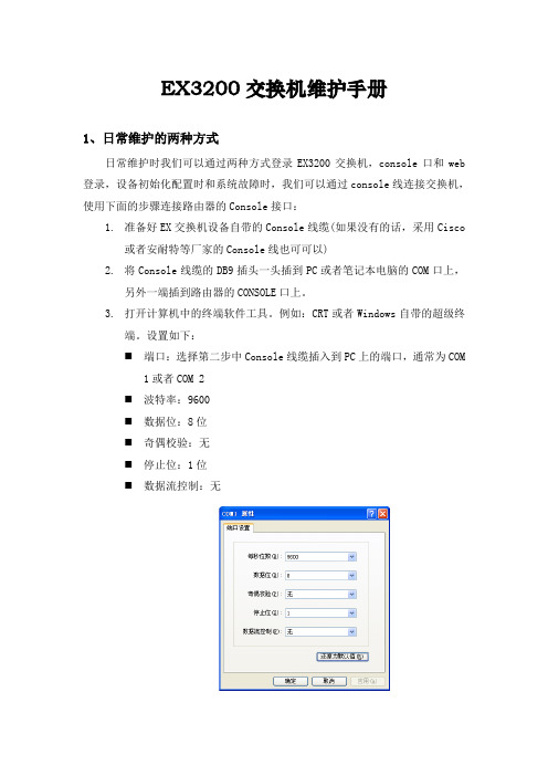
EX3200交换机维护手册1、日常维护的两种方式日常维护时我们可以通过两种方式登录EX3200交换机,console口和web 登录,设备初始化配置时和系统故障时,我们可以通过console线连接交换机,使用下面的步骤连接路由器的Console接口:1.准备好EX交换机设备自带的Console线缆(如果没有的话,采用Cisco或者安耐特等厂家的Console线也可可以)2.将Console线缆的DB9插头一头插到PC或者笔记本电脑的COM口上,另外一端插到路由器的CONSOLE口上。
3.打开计算机中的终端软件工具。
例如:CRT或者Windows自带的超级终端。
设置如下:⏹端口:选择第二步中Console线缆插入到PC上的端口,通常为COM1或者COM 2⏹波特率:9600⏹数据位:8位⏹奇偶校验:无⏹停止位:1位⏹数据流控制:无4.打开配置到的CRT或者超级终端,按“Enter”键,屏幕出现登陆的提示符,即连接成功。
如果没有显示,请检查线缆或者终端的配置是否正确。
2、EX3200交换机配置详细说明下面我们以仪征农信社配置为例来对配置加以详细说明:YZ_YZ_KF_SW_1 (ttyu0)login: jsnxPassword:#设备登录的用户名/密码:jsnx/juniper123 #--- JUNOS 10.0R4.7 built 2010-08-22 02:54:43 UTCjsnx@YZ_YZ_KF_SW_1>jsnx@YZ_YZ_KF_SW_1> configureEntering configuration mode#进入设备配置模式#[edit]jsnx@YZ_YZ_KF_SW_1# run show configuration |display setet version 10.0R4.7set system host-name YZ_YZ_KF_SW_1set system time-zone Asia/Shanghai#设备命名为YZ_YZ_KF_SW_1(扬州地区_仪征_开发网_交换机_1)#set system root-authentication encrypted-password "$1$.QxXIQNC$suZg5pmx8bOXUM1ytZQSd1"set system login user jsnx uid 2000set system login user jsnx class super-userset system login user jsnx authentication encrypted-password "$1$zPDEH7v8$XtL3zeN8fHagcfXQdtobn/"set system services ssh root-login denyset system services telnetset system services web-management http port 8480set system syslog user * any emergencyset system syslog file messages any noticeset system syslog file messages authorization infoset system syslog file interactive-commands interactive-commands anyset chassis alarm management-ethernet link-down ignore#设置设备的超级用户密码、开启http服务和telnet服务#set interfaces ge-0/0/1 unit 0 family ethernet-switchingset interfaces ge-0/0/2 unit 0 family ethernet-switchingset interfaces ge-0/0/3 unit 0 family ethernet-switchingset interfaces ge-0/0/4 unit 0 family ethernet-switchingset interfaces ge-0/0/5 unit 0 family ethernet-switchingset interfaces ge-0/0/6 unit 0 family ethernet-switchingset interfaces ge-0/0/7 unit 0 family ethernet-switchingset interfaces ge-0/0/8 unit 0 family ethernet-switchingset interfaces ge-0/0/9 unit 0 family ethernet-switchingset interfaces ge-0/0/10 unit 0 family ethernet-switchingset interfaces ge-0/0/11 unit 0 family ethernet-switchingset interfaces ge-0/0/12 unit 0 family ethernet-switchingset interfaces ge-0/0/13 unit 0 family ethernet-switchingset interfaces ge-0/0/14 unit 0 family ethernet-switchingset interfaces ge-0/0/15 unit 0 family ethernet-switchingset interfaces ge-0/0/16 unit 0 family ethernet-switchingset interfaces ge-0/0/17 unit 0 family ethernet-switchingset interfaces ge-0/0/18 unit 0 family ethernet-switchingset interfaces ge-0/0/19 unit 0 family ethernet-switchingset interfaces ge-0/0/20 unit 0 family ethernet-switchingset interfaces ge-0/0/21 unit 0 family ethernet-switchingset interfaces ge-0/0/22 unit 0 family ethernet-switchingset interfaces ge-0/0/23 unit 0 family ethernet-switchingset interfaces ge-0/1/0 unit 0 family ethernet-switchingset interfaces xe-0/1/0 unit 0 family ethernet-switchingset interfaces ge-0/1/1 unit 0 family ethernet-switchingset interfaces xe-0/1/1 unit 0 family ethernet-switchingset interfaces ge-0/1/2 unit 0 family ethernet-switchingset interfaces ge-0/1/3 unit 0 family ethernet-switching#设置设备的接口是二层交换模式#set interfaces lo0 unit 0 family inet address 66.192.250.1/32#设置设备的loopback0接口的IP地址#set interfaces me0 unit 0 family inet address 192.168.254.1/30#设置设备背后的管理口的IP地址#set interfaces vlan unit 64 description OAset interfaces vlan unit 64 family inet address 66.192.64.254/24 #设置Vlan 64为OA网段,配置其IP地址#set interfaces vlan unit 97 description kaifawangset interfaces vlan unit 97 family inet address 66.192.97.254/24 #设置Vlan 97为开发网段,配置其IP地址#set interfaces vlan unit 128 description SHIPINset interfaces vlan unit 128 family inet address 66.192.128.254/24 #设置Vlan 128为视频网段,配置其IP地址#set protocols ospf enableset protocols ospf area 0.0.0.0 interface ge-0/0/0.0set protocols ospf area 0.0.0.0 interface vlan.64set protocols ospf area 0.0.0.0 interface vlan.128set protocols ospf area 0.0.0.0 interface vlan.97set protocols ospf area 0.0.0.0 interface lo0.0#启用OSPF路由协议,加入网段和L0接口#set protocols igmp-snooping vlan allset protocols rstpset protocols lldp interface allset protocols lldp-med interface allset ethernet-switching-options storm-control interface all set vlans vlan128 vlan-id 128set vlans vlan128 interface ge-0/0/10.0set vlans vlan128 interface ge-0/0/11.0set vlans vlan128 interface ge-0/0/12.0set vlans vlan128 interface ge-0/0/13.0set vlans vlan128 l3-interface vlan.128set vlans vlan64 vlan-id 64set vlans vlan64 interface ge-0/0/2.0set vlans vlan64 interface ge-0/0/3.0set vlans vlan64 interface ge-0/0/4.0set vlans vlan64 interface ge-0/0/5.0set vlans vlan64 interface ge-0/0/6.0set vlans vlan64 interface ge-0/0/7.0set vlans vlan64 interface ge-0/0/8.0set vlans vlan64 interface ge-0/0/9.0set vlans vlan64 l3-interface vlan.64set vlans vlan97 vlan-id 97set vlans vlan97 interface ge-0/0/14.0set vlans vlan97 interface ge-0/0/15.0set vlans vlan97 interface ge-0/0/16.0set vlans vlan97 interface ge-0/0/17.0set vlans vlan97 interface ge-0/0/18.0set vlans vlan97 interface ge-0/0/19.0set vlans vlan97 interface ge-0/0/20.0set vlans vlan97 interface ge-0/0/21.0set vlans vlan97 interface ge-0/0/22.0set vlans vlan97 interface ge-0/0/23.0set vlans vlan97 l3-interface vlan.97#设置交换机的端口加入不同的网段#set poe interface all disable#关闭交换机上POE供电的功能#3、EX3200交换机上信息命令行查看在EX3200的交换机上我们可以通过以下命令来参看一些日常的维护信息:通过run show vlans命令我们可以查看到现有EX3200交换机各端口所属Vlan的信息。
docu52663_EMC-VNXe-系列-更换-VNXe3200-中的-DPE-存储处理器部件
EMC® VNXe®更换 VNXe3200 中的 DPE 存储处理器部件302-000-204REV 015 月, 2014本文档介绍如何更换 VNXe3200 的磁盘处理器存储模块中的存储处理器 (SP) 部件。
可以从存储模块的后部检修 SP 部件。
包括下列主题:u准备工作 (2)u更换出现故障的硬件组件 (3)u退回出现故障的部件 (15)准备工作在开始更换程序之前,请确保您已正确识别发生故障的部件,并且有可用的更换部件。
有关如何识别故障、订购新部件以及处理硬件组件的说明,请参阅 EMC®VNXe®联机帮助(“维修您的系统 > 添加或更换出现故障的硬件组件 > 更换出现故障的硬件组件”)。
请查看“卸下或更换组件前要遵从的注意事项”。
处理可换部件本节介绍当卸下、安装和存储任何可换部件时必须采取的防范措施和必须遵循的一般操作过程。
电源问题和 FRU存储系统已设计为不间断通电。
大多数组件可热插拔,即可以在存储系统运行时更换或安装这些组件。
前挡板应始终安装并且每个隔间应包含一个 FRU 或填充面板,以确保符合 EMI 要求并在 FRU 上保持适当通风。
在有可用的更换部件前,不应卸下出故障的 FRU。
更换或安装 FRU 时,即使只是触碰也有可能不经意地损坏设备中的敏感电子电路。
身体上积聚的静电 (ESD) 会通过这些电路放电。
如果工作区域的空气非常干燥,在工作区域使用加湿器将有助于降低 ESD 损坏的风险。
请按照下面的程序操作以防止损害设备。
阅读和理解以下说明:u对设备进行操作时应有足够的空间。
清理工作现场的所有不必要材料或本身会产生静电的材料,例如泡沫包装、泡沫杯、玻璃纸包装材料和类似的物品。
u请勿将更换或升级 FRU 从其防静电包装中取出,除非您已准备好安装它们。
u在维修服务器之前,收集 ESD 工具箱和所需的所有其他材料。
一旦开始维修,应避免离开工作现场,否则您可能集聚静电。
VNXe3200详细安装配置文档
VNXe2详细安装配置文档信息文档修订记录目录一、设备初始化 (4)1、VNXe Connection Utility向导 (4)2、完成初始化向导 (7)3、升级微码 (16)4、连接IO模块 (19)二、存储空间配置 (21)1、Hot Spare Policy (21)2、Storage Pools (21)3、LUNs配置 (26)三、服务器配置 (30)1、Hosts及Initiators配置 (30)2、LUNs映射 (35)四、修改存储管理IP (37)一、设备初始化1、VNXe Connection Utility向导初始化的过程需要配置设备的管理地址、掩码和网关。
用户名和密码并不是在这里进行配置的。
选择语言:程序会自动扫描设备:选中要初始化的产品SN,点击下一步,填入设备的名称及对应的IP信息(可选禁用、自动分配及手动静态IP):确认后初始化程序会配置设备的IP信息,并测试网络是否连通。
2、完成初始化向导初始化完成之后可以点击Start Unisphere进入IE管理页面,也可以直接关闭在IE里输入IP进行操作。
VNXe默认的初始用户名:admin密码:Password123#(P为大写字母,进入管理界面后会提示修改密码)在IE窗口直接输入设备的管理IP,选择“是”进入登陆界面:输入用户名密码:进入Unisphere Configuration Wizard,选择下一步:选择接受License Agreement,下一步,修改Admin password (Service password),密码必须包括:数字、大小写字母、特殊符号!.#$%^*_~:下一步,进行License注册(License提前在EMC官网注册并下载),选择Install License File,在弹出框中选择浏览到下载好的License文件并upload即可:下一步,进行DNS、NTP配置,如有相关环境,填写相应的IP 地址,添加即可,若无相关环境,可直接跳过:接下来提示是否配置存储空间(可跳过):这一步配置EMC Support信息,可跳过:下一步,此处可选择是否使用ConnectEMC,以及SMTP Mail Server的配置(可不填):配置ISCSI端口(可跳过):创建NAS Server(可跳过):下一步,配置概述,选择Finish完成即可:至此,初始化向导完成。
docu52702_将-VNXe3200-系统与-CIFS-文件系统配合使用

EMC® VNXe®系列将 VNXe 系统与 CIFS 文件系统配合使用VNXe Operating Environment 版本 3.0.X.X部件号 302-000-191修订版 02䖲版权所有 © 2015 EMC Corporation。
保留所有权利。
中国印刷。
2015年3月出版EMC 确信本出版物在发布之日内容准确无误。
该信息如有更改,恕不另行通知。
本出版物的内容按“原样”提供。
EMC CORPORATION 对本出版物的内容不提供任何形式的陈述或担保,明确拒绝对有特定目的的适销性或适用性进行默示担保。
使用、复制或分发本出版物所描述的任何 EMC 软件都要有相应的软件许可证。
EMC2、EMC 和 EMC 徽标是 EMC Corporation 在美国和其他国家/地区的注册商标或商标。
此处使用的所有其他商标均为其各自 所有者的资产。
有关您的产品系列的最新法规文档,请访问 EMC 在线支持网站上的“技术文档和咨询”部分。
2将 VNXe 系统与 CIFS 文件系统配合使用目录前言第 1 章设置主机以使用 VNXe CIFS 文件系统存储设置主机以使用 VNXe CIFS 存储的要求 (10)VNXe 系统要求 (10)网络要求 (10)Windows Active Directory 域中的 VNXe CIFS NAS 服务器 (10)独立 VNXe CIFS NAS 服务器 (10)用于 CIFS 环境中 VNXe 主机的主机软件 (11)用于 CIFS 环境中 VNXe 主机的软件概述 (11)安装用于 CIFS 环境的主机软件 (12)使用 Windows Continuous Availability (CA) (13)使用网络高可用性 (13)链路聚合 (14)配置链路聚合 (15)使用 CIFS 加密 (16)为主机(客户端)配置 VNXe CIFS 文件系统存储 (17)配置用户对 Active Directory 中 CIFS 共享的访问权限 (17)在主机上映射 CIFS 共享 (17)第 2 章将 CIFS 数据迁移到 VNXe 系统CIFS 迁移环境和限制 (20)迁移 CIFS 数据 (21)第 3 章用 Windows 工具管理 VNXe CIFS 文件系统存储打开计算机管理 MMC (24)在使用 MMC 插件之前 (24)用 MMC 创建共享并设置 ACL (24)在创建共享或设置访问权限 (ACLS) 之前 (24)设置 NAS 服务器上现有共享的 ACL (24)在 NAS 服务器上创建共享并设置其 ACL (25)使用主目录功能 (25)使用主目录时的限制条件 (26)向活动目录添加主目录 (26)添加带表达式的主目录 (26)使用组策略对象 (GPO) (28)VNXe NAS 服务器上的 GPO 支持 (28)使用 SMB 签名 (30)使用 MMC 监视 NAS 服务器连接和资源使用情况 (30)监视 NAS 服务器上的用户 (30)监视对 NAS 服务器上共享的访问 (30)监视 NAS 服务器上文件的使用情况 (31)审核 CIFS 用户和对象 (31)在 NAS 服务器上启用审核 (32)查看审核事件 (34)禁用审核 (34)访问 VNXe NAS 服务器的安全日志 (35)使用 Windows 资源管理器复制共享快照 (35)使用 Windows Explorer 恢复共享快照 (35)将 VNXe 系统与 CIFS 文件系统配合使用3目录第 4 章使用 VNXe 系统的文件级保留FLR 术语和概念 (38)FLR 术语 (38)基本 FLR 概念 (38)文件级保留的工作原理 (38)FLR 限制 (39)文件级保留的系统要求 (40)Windows .NET Framework 要求 (40)FLR Monitor 的 Windows 服务和服务帐户权限要求 (40)在主机上安装 FLR 工具包 (41)配置 FLR Monitor (42)使用 FLR Monitor (43)将只读文件提交至 FLR 状态 (43)创建 FLR 查询 (43)第 5 章将 VNX Event Enabler 通用解决方案与 VNXe 系统配合使用CAVA 概述 (46)VNXe NAS 服务器 (46)VEE CAVA 病毒检查客户端 (47)第三方防病毒软件支持 (47)VEE CAVA 软件 (47)EMC VNX CIFS 管理插件 (47)系统要求和限制 (47)文件级保留 (47)非 CIFS 协议 (48)为 VNXe NAS 服务器设置 VEE CAVA (48)4将 VNXe 系统与 CIFS 文件系统配合使用前言作为改进其产品线的一项措施,EMC 会定期发布其软件和硬件产品的修订版。
3200 Series Meters 安装手册

3200 Series Meters Installation Qualification Operation Qualification Performance Verification Reference DocumentTable of Content1. Introduction (3)1.1 General Information (3)1.2 Meter Information (3)1.3 Required Materials (3)1.4 Meter Keys (5)1.5 Meter connections (5)2. Installation Qualification (5)2.1 Overview (5)2.2 Meter Information (6)2.3 Enviro nment Condition (6)2.4 Document Inspect (6)2.5 Component Check (6)2.6 Reference Standard Information (6)3. Operation Qualification (6)3.1 Meter Power Supply (7)3.2 Meter Self-Test (7)3.3 Manual Temperature Verification (8)3.4 pH electrode Calibration (8)3.5 ISE electrode Calibration (8)3.6 DO Probe Calibration (8)3.7 Conductivity Probe Calibration (9)4. Performance Verification (10)5. Appendix Documents (10)1. Introduction1.1 General InformationThis standard operating procedure (SOP) defines the procedure for the installation qualification, operation qualification and performance verification (IQ/OQ/PV) of Agilent 3200 series meters. This procedure provides a guideline to generate the data necessary to validate or qualify the Agilent 3200 series meters.This SOP is applicable to all Agilent 3200 series meters that are used in a regulated lab. And this SOP can be used as a reference for customer to develop their own IQ/OQ/PV documents. It’s customers’responsibility to develop and maintain the IQ/OQ/PV SOP for their specific applications.1.2 Meter InformationInstallation qualification and operation qualification are required for all new meters used in a regulated environment. The meters will not be released for regulated use until the installation qualification and operation qualification have been performed with passing result.1.3 Required MaterialThe following materials are required to perform the IQ/OQ/PV on Agilent 3200 series meters ∙Short circuit plug, PN: G4383-40000, shipped with 3200P/3200M/3200I∙Conductivity diagnostic tool, PN:5185-8391, shipped with 3200C/3200M∙ATC temperature diagnostic tool, PN: 5185-8390, shipped with3200P/3200M/3200I/3200C/3200D∙Manuals/User GuideFor 3200P/3200M with pH function:∙pH electrode or pH combination electrode or pH triode combination electrode, with BNC connector∙pH buffersPart Number Package Shelf Life1 pH4.001 buffer (NIST) 5190-0535 3 x 250ml 15 months pH7.00 buffer (NIST) 5190-0537 3 x 250ml 15 months pH10.01 buffer (NIST) 5190-0536 3 x 250ml 15 months2 pH4.00 buffer (GB) 5190-05383 x 250ml 15 months pH6.86 buffer (GB) 5190-0539 3 x 250ml 15 months pH9.18 buffer (GB) 5190-0540 3 x 250ml 15 months3 pH buffer package (4.01、7.00、10.01) (NIST)5190-0533 3 x 250mL 15 months4pH buffer package (4.00、6.86、9.18) (GB)5190-0533 3 x 250mL 15 months Select one option from the list. Each option contains three standard buffers.For 3200I/3200M with ISE function:∙Ion selective electrode (ISE) with BNC connector∙Certified ISE standards appropriate for ion selective electrode, for example, NaF for fluorion measurement with I9111 Fluoride combination ISE. Agilent don’t supply ISE standards.For 3200C with conductivity function:∙Conductivity probe with 3 pin mini DIN connector∙Certified conductivity standards appropriate for conductivity probe. Agilent don’t supply conductivity standards.For 3200D with DO function:∙Dissolved Oxygen probe with 4 pin miniDIN connector∙Zero Oxygen solution for Zero Oxygen Calibration, freshly prepared by customers.1.4 Meter Keys1.5 Meter ConnectionsAll connectors on 3200M are listed above. 3200P/3200I/3200D/3200C will have fewer connectors. For example, 3200P with all these listed connectors except Conductivity 3 pin MiniDIN connector.1.6 Qualification Scope 1.6.1 Installation QualificationVerify and document that a system is installed according to written and pre-approvedspecification. Provide assurance that the system specified for a particular function was received, installation procedures were followed and the system was installed according to customer/manufacturer ’s specifications.1.6.2 Operation QualificationVerify and document that a system operates according to written and pre-approvedspecification throughout. Provide assurance that the system operates according to BNC Connector4 pin MiniDIN3 pin MiniDIN Connectorcustomer/manufacturer’s specifications.1.6.3 Performance VerificationVerify and document the measurement accuracy and precision according tospecifications.2. Installation Qualification2.1 OverviewBefore performing the IQ/OQ/PV, examine the meter for abnormal conditions such as corrosion, deterioration, loose components, broken parts and environmental conditions. Correct any of these conditions before installation.Installation qualification of new meters includes verifying meter information, reviewing pre-installation requirements and confirming environment conditions.2.2. Meter Information2.2.1 Record the start date.2.2.2 Record the location of the meter.2.2.3 Record the person responsible for the meter.2.2.4 Describe the meter appearance.2.2.5 Describe the application or purpose of the meter.2.3 Environmental ConditionsInspect the site prior to installation and verify that all the meter operating conditions are met. Check the electrical/power supply. Inspect the equipment for abnormal conditions. Record and correct all abnormal conditions.2.4 Documentation Inspection2.4.1 Obtain all manuals supplied with the meter.2.4.2 Record the part number and title of theses manuals.2.4.3 Check the certificate of the meter.2.5Component Check2.5.1 Give a detailed description of all meter components.2.5.2 Record the information for all components including the component type, serial number and firmware version.2.6Reference Standards Information2.6.1 Record the last calibration data and calibration due date2.6.2 Check the Standards shelf life3 Operational QualificationOperation qualification of new meters demonstrates correct meter operation by verifying themeter self-test and pH, ORP, ISE, DO and conductivity functionality.For detailed calibration procedures refer to the User Guide of 3200 series meters.3.1 Meter Power SupplyCheck the power adapter input and output.They should meet:Input 240 VAC, 1 AOutput 9VDC, 800mA3.2 Meter Self-Test3.2.1 Temperature test for all meters∙Connect the ATC temperature diagnostic tool (PN:5185-8390) to the Temp. socket of meters;∙Turn on the meter to enter into measurement state.∙The meter should display a temperature reading between 49.0 to 51.0 °C.3.2.2 Check the potential (mV) value for 3200P/3200I/3200M∙Disconnect the pH electrode.∙Connect the short circuit plug (PN:G4383-40000) to the pH socket.∙Turn on the meter.∙Start measuring pH.∙The meter should display a potential (mV) reading between -0.5 to 0.5 mV (also called mV Zero).3.2.3 Check pH value for 3200P/3200M∙Disconnect the ATC probe if plugged.∙Set the temperature to 25 °C manually.∙Connect the short circuit plug (PN:G4383-40000) to the pH socket.∙When the potential (mV) is zero, the meter should display pH 7.00 (±0.01).3.2.4 Check pX value for 3200I/3200M∙Disconnect the ATC probe if plugged.∙Set the temperature to 25 °C manually.∙Connect the short circuit plug (PN:G4383-40000) to the pH socket.∙When the potential (mV) is zero, the meter should display pX 2.00 (±0.01).3.2.5 Check for current Response for 3200D/3200M∙Connect the meter with the ATC temperature diagnostic tool (PN:5185-8390) shipped with the meter.∙Turn on the meter. Enter the measurement state.∙The meter should display a current between 680 to 720 nA.∙When the diagnostic tool is unplugged, the meter should display a current from 0 to 5 nA.3.2.6 Check conductivity for 3200C/3200M∙Disconnect the ATC temperature diagnostic tool if plugged and manually set the temperature to 25°C.∙Connect the meter with conductivity diagnostic tool (PN:5185-8391) shipped with the meter.∙Turn on the meter. Enter the measurement state.∙It will display:Conductivity: nearly 100 μS/cmResistance: nearly 10 kΩ·m3.3 Manual Temperature Verification∙Disconnect all of the electrodes and probes from the meter.∙In the measurement mode, the temperature display should be 25.0±0.1°C3.4 pH Electrode Calibration (Meters with pH function)The calibration points should cover the expected pH range of the samples to be measured. The calibration points should be not less than 1 pH unit apart and not more than 4 pH units apart. Fresh buffers should be used for each calibration.∙Prepare the electrode and ATC probe (if necessary). Connect the electrode and ATC probe to the meter.∙Select appropriate standard solution and press [Calibration]key from the meter interface.∙Clean pH electrode, reference electrode (if separated) and ATC probe (if separated).Put them in the buffer to be calibrated.∙When the reading becomes stable, press [Enter]key and the meter will display ‘Storing……’ and save calibration data.∙Repeat until all buffers are calibrated.∙After calibration, you could review the actual electrode slope, in percent. The slope must be in the range of 90% to 102%.3.5 ISE Electrode Calibration (Meters with ISE function)The calibration standards should cover the expected concentration of the samples to be measured and the calibration range should be at least ten times greater than the lowest calibration point.Control the calibration solution and sample solution at the same temperature. If not, the measuring accuracy and reproducibility will be affected. Calibrate ISE in these solutions from low concentration to high concentration. Fresh standards should be used for each calibration.∙Prepare the ISE and ATC probe (if necessary). Connect the electrode and ATC probe to the meter.∙Select ion mode and press [Calibration] from the meter interface.∙Clean ISE and ATC probe (if necessary). Put them in standard solutions to be calibrated in order from low to high concentration.∙When the reading becomes stable, press [Enter]key and the meter will display ‘Storing……’ and save calibration data.∙Repeat until all buffers are calibrated.∙After calibration, you could review the actual electrode slope, in percent. The slope must be in the range of 90% to 102%.3.6 DO Probe Calibration (Meters with Dissolved Oxygen function)∙Prepare the DO probe and connect it to the meter.∙You may select either ‘Zero Oxygen Calibration’ or ‘Full Scale Calibration’ from the meter interface.∙Full Scale Calibration:Thoroughly rinse the DO probe with DI water; Dry it with a soft tissue on the membrane surface. To calibrate with air, put the probe in a well-ventilated area.OR calibrate with water saturated with air as below,Swirl the probe at a speed of 20–80 cm/s or stir the water to produce a similar linear speed. Keep the flow speed constant during calibration. Ensure there is no air bubble trapped under the membrane.From the initial state or while measuring, press [Calibrate]; Select Full Scale. Press [Enter]; when reading becomes stable, press [Enter] to automatically record the Full Scale response. This ends Full Scale Calibration.∙Zero Oxygen CalibrationPrepare zero-oxygen water by dissolving 12.5 g AR grade anhydrous sodium sulfite in 250 mL DI water; Soak the measuring tip in zero oxygen water and gently shake the probe to remove bubbles on the gas permeation membrane surface; From the initial state or while measuring, press [Calibrate]; Select Calib Zero; Press [Enter] to select Zero Point Calibration.When reading becomes stable, press [Enter] to automatically record the Zero Point value. This ends Zero Oxygen Calibration.3.7 Conductivity Probe Calibration (Meters with Conductivity function)3.7.1 Prepare the conductivity probe and connect it to the meter.3.7.2 Calibrate the cell constant∙Prepare a standard solution (KCl) according to page 37 of 3200C User Guide.∙Ensure the meter is connected with both a conductivity probe and an ATC probe.Record the actual temperature of sample solution.∙Disconnect the ATC probe. The meter will display 25.0 °C by default. Pay attention to: If the temperature is set at 25.0 °C manually, conductivity displayed is without temperature compensation.∙Rinse the conductivity probe with distilled or DI water. Soak the conductivity probe in the standard solution.∙Press [Calibrate]. Select Cell Const.∙Press [Setup] to enter a Standard Solution Value (STD Value).You could find the proper STD value on page 39 of 3200C User Guide with the temperature recorded.∙When the reading stabilizes, press [Enter]. The meter will calculate and set the new cell constant. The calibration is done.3.7.3 Calibrate the TDS∙Select a proper standard solution according to the nature and conductivity range of sample.∙Set the cell constant to the value written on the probe label or recalibrate the probe to get a new cell constant in 3.7.2.∙Press [Calibrate] and select TDS Factor. Press [Enter] to enter Calibration mode.∙Rinse the conductivity probe with DI water.∙The temperature of the calibration solution should be 25.0 ± 0.1 °C.∙Soak the conductivity probe in the standard solution.∙Press [Setup].∙Enter an STD value (mg/L) given in Table 6 on page 41 of 3200 C User Guide.∙When the reading becomes stable, press [Enter].∙The meter automatically calculates and sets a new TDS factor. Calibration is done.4. Performance VerificationFor performance verification, evaluation of accuracy, inter-assay RSD and intra-assay RSD will consist of at least three measurement sets. Each set will measure pH of three test samples representing low, medium and high pH value. The test buffers were the same as the standard buffers. To evaluate precision of the inter-assay and the intra-assay, three measurement sets must be conducted in three different days. The acceptance criterion is bracketed in the table in appendix document.The accuracy and the precision of pH meter should be validated. Measure three testing buffers. Each buffer is measured six times continuously. Repeat the procedure three times; each repeat should be at least 24 hours apart. Calculate intra-day and inter-day RSD%.5. Appendix5.1 Change history5.5 IQ - Documentation Inspection5.6 Buffers Used in the QualificationThe standard buffers were purchased from _________.5.7 OQ – Meter Self-TestSelf Test ___________Passed ______________Failed Observations: ______________________________________________________________5.8 OQ – Manual Temperature VerificationTemperature: _______________ ________Passed ________Failed Specification: 25.0 ± 0.1 °CObservations: ______________________________________________________________5.9 OQ – pH Electrode CalibrationpH Electrode Calibration ____________Passed ____________Failed pH Electrode Information (Model/Lot/Serial Number) ________________________________5.10 OQ – ISE Electrode CalibrationISE Electrode Calibration ____________Passed ____________Failed ISE Electrode Information (Model/Lot/Serial Number) ________________________________5.11 OQ – DO Probe CalibrationDO Probe Calibration ____________Passed ____________Failed5.12 OQ – Conductivity Probe CalibrationConductivity Probe Calibration ____________Passed ____________Failed Conductivity Probe Information (Model/Lot/Serial Number): _________________________5.13 PV– Accuracy and the Precision Test。
VNXe3200初始化配置之如何初上手讲解
VNXe 3200 初始化配置之如何初上手VNXe3200是EMC统一存储部门2014年新推出的一款功能强大、经济实用、面向中小企业的一款存储产品。
这款产品自从上市以来,一直受到用户的好评,产品销量一直上升。
作为EMC该产品一线的技术支持工程师,我很荣幸能够有机会在这里和大家一起探讨使用VNXe3200过程中遇到的一些常见的问题。
今天,我会从最开始的第一步开始介绍,如何上手,如何配置一款新的VNXe3200设备。
也许很多用户会第一时间想到VNXe3200 Connection Utility。
对的,但是在初始化配置的过程中,会不会遇到一些难缠的问题呢?有没有一些更巧妙的小招呢?答案是肯定的。
这篇博客就是在这样的需求下,结合本人第一线产品技术支持的经验,向大家介绍如何快速上手初始化配置一台新的VNXe3200存储。
1. 使用VNXe 3200 Connection Utiliy1.1 Connection Utility 介绍VNXe Connection Utility是一款简单的,能够帮助客户在初始化时为VNXe设备配置主机名称和管理IP的工具。
1.2 Connection Utility下载和安装如果您想为 VNXe 系统管理端口手动分配静态 IP 地址,则必须安装并运行VNXe Connection Utility。
VNXe Connection Utility 可为 VNXe 系统分配网络地址。
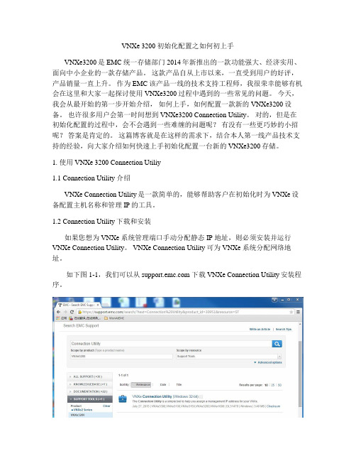
如下图1-1,我们可以从 下载VNXe Connection Utility安装程序。
图1-1 下载VNXe Connection Utility说明:虽然在软件上标注了Windows 32-bit,但是该VNXe Connection Utility 支持各种常见的Windows版本。
不过需要特别注意的是该软件只兼容 JAVA 7及其之前的版本。
1.3 Connection Utility 使用当在Windows工作机上成功安装好Connection Utility软件。
VNXE3200配置文档以及多路径安装
登录方法浏览器输入存储地址,登录存储输入用户名密码,点击login主界面如下4.2 RAID创建已经创建好无需要再次操作点击storage 选择storage configuration选择storage pools点击下方的create开始创建输入池名称选择RAID类型点击OK,之后选择默认操作,点击NEXT完成后提示创建过程用同样的方法创建POOL_NL_SAS4.3创建主机连接好存储与SAN交换机的光纤跳线后点击hosts选择hosts,点击created hosts输入对应服务器的host名称选择操作系统点击next,输入IP地址(此IP不起实际作用)点击next直到一下步骤,选择服务器对应的WWN号后,点击NEXT点击finish完成主机创建lun创建过程点击storage,之后选择luns如下图点击create ,进入到lun创建过程输入lun名称,点击next选择对应的存储池输入大小,点击NEXT选择不创建快照选择要给映射的主机,之后点击access选项,选择lun点击finishe,完成lun创建最终lun状态如下4.5 多路径软件的安装安装多路径是为了保证磁盘的冗余性安装过程如下4.5.1 windows下的安装打开服务器管理器添加新功能点击下一步直到安装功能选项选择多路径IO,点击下一步直到安装完成完成后打开控制面板,选择MPIO点击发现多路径发现多路径设备后点击添加,提示重启重启完成虎完成多路径的安装之后对磁盘初始化即可4.5.2 linux下的配置首先确认系统是否安装multpath软件,如果没有先安装(1)拷贝multpath.conf 文件到etc目录下root下执行cp /usr/share/doc/device-mapper-multipath-0.4.9/multipath.conf /etc/命令(2)设置多路径服务开机自动启动,root下执行chkconfig multipathd on命令(3)启动multipathd服务root下执行service multipathd start(4)查看multipath路径状态并记录磁盘ID使用multipath –ll命令图中3600字数为磁盘ID,可查看大小以及多路径状态(5)编辑/etc/multipathd.conf文件执行命令vi /etc/multipathd.conf添加如内容multipath {wwid 此处输入磁盘IDalias 磁盘名}如下图(6)重启multpath服务执行service multpathd restart 重启服务(7)使用多路径硬盘在/dev/mapper下可以看到生成的多路径磁盘,之后对磁盘格式化即可例如。
EX3200配置笔记
CLI有两种模式:用户模式和配置模式,用户模式的提示符是>,配置模式的提示符是#,在数用户模式下输入configure或者edit可以进入配置模式;由于是层次化结构,因此配置一个参数有两种方式,一是在最外层使用一条set命令将所有层的参数一次写完,另外一种方式是利用edit逐层进入需要配置参数的层次,然后用set命令直接设置参数。
方法一:lab@EX4200# set protocols ospf area 0 interface ge-0/0/1.0 hello-interval 10在edit这种方式中,exit可以退回上一次用edit 进入以前的层,直接输入top则退回最上层:另外,juniper的配置参数有些可以一次写几个,比如要一次配置ospf的hello-time和dead-time可以按照下面写法:lab@EX4200# set protocols ospf area 0 interface ge-0/0/1.0 hello-interval 10 deadinterval10 注意:如果不知道一条命令里面后面是否还可以跟其它配置参数,那么最好使用? 帮助一下:lab@EX4200# set protocols ospf area 0 interface ge-0/0/1.0 hello-interval 10 ?交换机JUNOS命令配置中,可以使用TAB 键和空格键来进行参数的补全,在补全系统参数中两个键的作用是一样的,例如:lab@EX4200# set pro <-输入TAB键或者空格键,则会补全protocolslab@EX4200# set protocols在用户模式下,是无法进行配置操作的,而只能查看系统的一些参数。
所以用户模式下的show命令是查看系统参数。
要看系统配置则使用show configure命令。
因此说用户模式和配置模式下的show命令是不同的,如果要在配置模式下运行用户模式命令,则需要在命令前面加一个runlab@EX4200# run show interfaceslab@EX4200# run ping 172.27.69.8PING 172.27.69.8 (172.27.69.8): 56 data bytes64 bytes from 172.27.69.8: icmp_seq=0 ttl=64 time=5.118 ms64 bytes from 172.27.69.8: icmp_seq=1 ttl=64 time=7.949 ms64 bytes from 172.27.69.8: icmp_seq=2 ttl=64 time=7.018 ms^C--- 172.27.69.8 ping statistics ---3 packets transmitted, 3 packets received, 0% packet lossround-trip min/avg/max/stddev = 5.118/6.695/7.949/1.178 mslab@EX4200# run ping 172.27.69.8 命令等同于lab@EX4200> ping 172.27.69.8而在JUNOS中完全不同,我们操作(增加、删除、修改)的那份配置文件只是一个候选文件(candidate configure),并不是正在运行的配置文件,只有将候选文件通过commit提交之后,配置才会真正的应用到当前系统使用的active 配置文件中,从而使得修改的配置生效。
- 1、下载文档前请自行甄别文档内容的完整性,平台不提供额外的编辑、内容补充、找答案等附加服务。
- 2、"仅部分预览"的文档,不可在线预览部分如存在完整性等问题,可反馈申请退款(可完整预览的文档不适用该条件!)。
- 3、如文档侵犯您的权益,请联系客服反馈,我们会尽快为您处理(人工客服工作时间:9:00-18:30)。
VNXe2详细安装配置
文档信息
文档修订记录
目录
一、设备初始化 (4)
1、VNXe Connection Utility向导 (4)
2、完成初始化向导 (9)
3、升级微码 (24)
4、连接IO模块 (28)
二、存储空间配置 (29)
1、Hot Spare Policy (29)
2、Storage Pools (30)
3、LUNs配置 (38)
三、服务器配置 (45)
1、Hosts及Initiators配置 (45)
2、LUNs映射 (52)
四、修改存储管理IP (54)
一、设备初始化
1、VNXe Connection Utility向导
初始化的过程需要配置设备的管理地址、掩码和网关。
用户名和密码并不是在这里进行配置的。
选择语言:
程序会自动扫描设备:
选中要初始化的产品SN,点击下一步,填入设备的名称及对应的IP信息(可选禁用、自动分配及手动静态IP):
确认后初始化程序会配置设备的IP信息,并测试网络是否连通。
2、完成初始化向导
初始化完成之后可以点击Start Unisphere进入IE管理页面,也可以直接关闭在IE里输入IP进行操作。
VNXe默认的初始用户名:admin密码:Password123#(P为大写字母,进入管理界面后会提示修改密码)
在IE窗口直接输入设备的管理IP,选择“是”进入登陆界面:
输入用户名密码:
进入Unisphere Configuration Wizard,选择下一步:
选择接受License Agreement,下一步,修改Admin password (Service password),密码必须包括:数字、大小写字母、特殊符号!.#$%^*_~:
下一步,进行License注册(License提前在EMC官网注册并下载),选择Install License File,在弹出框中选择浏览到下载好的License 文件并upload即可:
下一步,进行DNS、NTP配置,如有相关环境,填写相应的IP 地址,添加即可,若无相关环境,可直接跳过:
接下来提示是否配置存储空间(可跳过):
这一步配置EMC Support信息,可跳过:
下一步,此处可选择是否使用ConnectEMC,以及SMTP Mail Server的配置(可不填):
配置ISCSI端口(可跳过):
创建NAS Server(可跳过):
下一步,配置概述,选择Finish完成即可:
至此,初始化向导完成。
3、升级微码
升级过程之中存储可实现在线升级,因为是两个SP一个升级完成后令一个再升级,一般来说是备用的先进行升级。
选择Settings -> More configuration… -> Update Software:
选择Upload Candidate Version上传微码:
然后选择Install Candidate Version 安装升级微码,按提示选择Install完成安装,重新启动Unisphere界面登录进入即可完成升级:
4、连接IO模块
VNXe3200增加了光纤IO模块,在初始化之后需要将IO模块添加到VNXe3200上,进入System -> System Health,选择Commit IO Module:
选择Yes,系统会在后台重启存储添加模块,详细信息可通过System -> Logs查看。
二、存储空间配置
1、Hot Spare Policy
进入Storage -> Storage Configuration -> Spare Disks,选择Hot Spare Policy,可以查看热备盘策略配置:
2、Storage Pools
VNXe 2代的RAID Group支持表有:
Raid Type Disk Number
Raid 5 RAID5(4+1)
RAID5(8+1)
RAID5(12+1)
Raid 6 RAID6(6+2)
RAID6(8+2)
RAID6(10+2)
RAID6(14+2)
Raid 10 Raid10(2+2), Raid10(3+3), Raid10(4+4),etc EMC Best Practices
Extreme performance flash tier RAID5 (4+1)
Performance SAS tier RAID5 (4+1) or (8+1)
Capacity NL-SAS tier RAID6 (6+2) or (8+2)
选择Storage -> Storage Configuration -> Storage Pools,选择Create 即可进行Storage Pool创建:
选择Quick Start则让系统自动配置,根据不同类型硬盘创建各自的Pool;选择Custom Storage Pool可手动配置RAID Pool:
填写Pool的名称:
选择存储池层及对应的RAID类型(VNXe对RAID有类型和盘
数限制):
下一步,选择该Pool中RAID或硬盘的数量:
下一步,确认Summary,选择Finish即可完成创建:
在Storage Pool的界面上,可以查看Pool的空间使用状况,也可以进行Pool的Expand、Detail等选项:
3、LUNs配置
选择Storage -> LUNs,可进入LUNs配置页面,选择Create:
选择Create a LUN,创建LUN,填写LUN名称:
选择要创建LUN的Pool,填写LUN的大小,以及选择是否开启精简配置Thin:
若需要配置Snapshot保护措施,选择Create a snapshot schedule;若无需配置,选择Do not configure a snapshot schedule:
选择可访问该LUN的主机,可在后续进行配置,详见第三章:
选择下一步,确认Summary信息,并Finish即可:
创建完成后,如图所示,选择Detail可以进行LUN属性修改。
三、服务器配置
1、Hosts及Initiators配置
连接好存储与服务器的光纤链路后,配置好光纤交换机,确认连接状态正常后,选择Hosts -> Initiator,可以查看连接到存储的Hosts 的HBA WWN信息:
进入Hosts -> Hosts,选择Create Host创建主机信息:
填写服务器名称:
选择操作系统Operating System(可不选):
填写服务器的IP地址(可不填):
选择ISCSI IQN号(如果是FC连接,可不选):
选择FC WWN号:
确认Summary信息,选择Finish即可完成Host创建:
2、LUNs映射
选择Storage -> LUNs,选择LUN的Detail详细属性:
选择Host Access标签进行服务器访问控制,选择Modify Access:
在弹出窗口,要设置可访问的Hosts,选择Access选项中的LUN:
确认即可,则服务器可访问该LUN:
四、修改存储管理IP
选择Settings中Management Settings,修改静态IPv4地址、掩码及网关:
修改地址会导致现有的Unisphere管理界面断开连接,需要重新连接:。
