ftServer2500-4400-6200安装介绍
F——Win NT系统软件安装
3.
4.
5.
Slide 15-8
设置从光驱启动
从光盘启动 ① 确保ftServer W系列系统光盘已经放入了光驱中 ②当系统开始启动,进程条开始填充的时候,按下ESC按键。这时会出现进入设置 的消息框,在启动菜单出现之前,这个消息框会消失。在启动菜单上,选择CDROM Drive ③按下Enter键 ④ 当出现消息“按任意键从光盘开始启动”时,按下键盘上的任一键
Slide 15-4
1. Windows Server 2003
IPL过程安装以下内容 过程安装以下内容
对于ft2510,2500,系统支持Windows Server 2003标准版和企业版 对于ft6210和4410,系统支持Windows Server 2003企业版
2. ftServer Windows系列系统管理软件 系列系统管理软件 系列
计划课时:2-3小时
容错服务器系统管理(一)
Windows Server 2003系统软件安装
上海海得控制系统股份有限公司 系统事业部
Slide 15-1
名词解释
IPL: Initial Program Load初始化程序加载 系统管理软件和操作系统初步安装在本地磁盘上,但没有经过个性化设 置,部分必需的第三方软件已经加载在本地磁盘但尚没有进行安装
IPL 过程 – 安装Win2003
Slide 15-12
IPL 过程 – 安装Win2003
► 不同的安装进度条出现,开始复制数据到系统到系统磁盘上
IPL 过程 – 安装Win2003
► 提示插入系统管理软件DOC盘(Disk 2 of 2)
IPL 过程 – 安装Win2003
► 提示插入Windows Server 2003 操作系统安装介质 (Disk 1/2)
华盛顿数据保护器单服务器版安装指南说明书

Installing the Data Protector Single Server Edition Installing the Data Protector Single ServerEditionThe Single Server Edition (SSE) of Data Protector is designed for smallenvironments where backups run on only one device connected to a CellManager. It is available for supported Windows and for HP-UX andSolaris platforms.To install the Cell Manager and (optionally) Installation Server, followthe instructions in “Installing the Data Protector Cell Manager (CM) andInstallation Server(s) (IS)” on page15.Limitations When considering the SSE license, be aware of the following limitations: Limitations of SSE for Windows•SSE supports backups to only one device concurrently, connected to asingle Cell Manager.•One 10-slot DDS autochanger only is supported.•UNIX (also HP-UX) clients and servers are not supported. If a backupis attempted to a UNIX machine, the session is aborted.•If a cell has a Windows Cell Manager, you can back up only Windowsclients. Backup to Novell Netware clients is not supported.•Adding extension products is not supported with SSE.•Clustering is not supported with SSE.•Disaster Recovery is not supported with SSE.The number of Windows clients is not limited.For supported devices, please refer to the HP OpenView Storage DataProtector Software Release Notes.Limitations of SSE for HP-UX and Solaris•SSE supports backups to only one device concurrently, connected to asingle Cell Manager.•One 10-slot DDS autochanger only is supported.135Installing the Data Protector Single Server Edition 136•On a UNIX Cell Manager, you cannot back up servers - only UNIX clients, Windows clients, Solaris clients, and Novell NetWare clients.•Adding extension products is not supported with SSE.•Clustering is not supported with SSE.The number of clients (UNIX, Windows) is not limited.For supported devices, please refer to the HP OpenView Storage Data Protector Software Release Notes .Installing aPassword For the step-by-step instructions on how to install a password on the Cell Manager, refer to “Installing a Password on the Cell Manager” onpage 280.。
PTN6200设备初始化及业务配置流程(技能比武)
PTN6200设备初始化及业务配置流程总体流程如下:6200设备初始化---设备连纤---连接T31网管服务器---打开T31网管创建网元---网元上载同步---创建纤缆连接---网元基础配置---创建隧道---创建伪线---创建业务。
一、6200设备初始化:1. 需要工具:ZXCTN6200设备电脑一台USB转RS232串口线(RJ45)一条6200初始化脚本2. 操作环境:电脑通过USB转串口线连接至6200设备主用主控板的CON口(主控板最右端的RJ45接口)3. 连接设备调试口使用电脑xp系统自带的超级终端连接设备,即在windows系统中打开“开始-所有程序-附件-通讯工具-超级终端“图1. 打开windows自带的超级终端,在新建连接中填入任意名称,点击确定。
图2.在“连接到”窗口中选择连接时使用COM3(注意COM口序号请以实际电脑为准)图口属性中点击“还原为默认值”,使其配置为“9600,8,无,1,无“即可。
图4.如果使用中兴公司的数据综合测试平台的话,选择协议为COM,波特率9600,其他默认即可。
4. 导入设备初始化脚本第一次连接设备后会显示:Zxr10>Zxr10>enable #输入enable命令Password: zxr10 #输入密码:zxr10Zxr10# # 进入特权模式进入#模式即特权模式后即可开始导入6200初始化脚本,将脚本命令直接复制粘贴即可(注意脚本中第一行应为“con t”即config terminal命令)。
将4个网元分别导入对应的脚本,注意检查各脚本对应的ip、vlan、端口是否正确。
导入完成后可输入命令show ip interface brief 查看相关的ip是否配置正确。
参考脚本如下:5.设备连纤设备初始化完成后即可将设备之间的光纤按现场提供的图示连接。
连接正确且光功率正常的话端口状态灯会亮。
注意按考试提供的表格内容为准检查各网元脚本是否正确(网元名称、loopback ip、端口、vlan和ip)6. 连接网管服务器将监控网线连接网管服务器电脑和接入网元的监控接口,将网管服务器电脑的ip设置为脚本上的snmp-server host ip,确认本地连接正常后,在网管服务器电脑上ping各网元loopback ip,如能ping通说明脚本无误且线路连接正常。
Stratus ftServer 容错服务器软件安装和配置手册

Stratus ftServer 容错服务器软件安装和配置手册制定本手册目的指引用户如何安装和配置容错W系列服务器的系统软件对象本手册是专供安装配置ftServer W系列容错服务器的系统软件管理员使用。
修订信息本手册是修订版。
它不再支持W3300,W5600和W6600。
另外,本次修订还包括:·W4300和W4400的步骤细节,W系列新的型号。
·使用ProSet9.0版本代替原来的ProSet4.0版本。
·如果你从Stratus购买了Windows 2003 Server操作系统,还将获得恢复光盘。
执行IPL和Post-IPL过程1、假如操作系统出厂的时候就已经安装好,机器设备的后面就会贴有微软认证的标签。
这种情况下,我们仅仅执行Post-IPL过程2、假如操作系统出厂的时候没有安装,那么,我们就要执行IPL过程3、重装W系列的操作系统(比如说,系统硬盘出现问题,并在远处维修),我们要重新执行IPL过程。
IPL过程安装以下内容:1、Windows Server 2003对于W2400,2500,系统支持Windows Server 2003标准版和企业版。
对于W4300和W4400,系统支持Windows Server 2003企业版。
2、ftServer W系列系统软件,包括硬件驱动,ftServer管理,ftServer管理控制台(ftSMC)和ftServer软件可用性管理(SAM)。
3、为VTM控制台提供Java2运行环境(JRE)。
4、Adobe Acrobat Reader软件。
5、为W系列定制的操作系统文件。
有关IPL的建议:1、假如操作系统已经安装,但没有正确运行,你无法判断是Windows操作系统的原因,还是ftServer系统软件的原因的话,重装IPL。
2、为实现容错,安装完后做DRD实现镜像功能。
这个操作既不属于IPL操作,也不属于Post-IPL操作。
4400系列电源包安装和操作说明书
PERLICK CORPORATION 8300 W. Good Hope Road, Milwaukee, WI 53223 • 800.558.5592 • MODELS 4400 Series 44044414-23044104410W 44144414W 44204420WCUSINSTALLATION AND OPERATION INSTRUCTIONS4400 SERIES POWER PAKSIMPORTANT INFORMATIONTo register your product, visit our web site at . Click on Commercial , then Service . You will see the link to Warranty Registration Form . You must complete and submit this form or the installation date will revert back to the ship date.Permanently mount the enclosed Warning/Safety Instruction label in a visible location near the CO2 regulator.This manual has been prepared to assist you in the installation of your Century Remote Beer System and to acquaint you with its operation and maintenance. We dedicate considerable time to ensure that our products provide the highest level of customer satisfaction. If service is required, your dealer can provide you with a list of qualified service agents. For your own protection, never return merchandise for credit without our approval.We thank you for selecting a Perlick product and assure you of our continuing interest in your satisfaction.Table of ContentsSizes & Specifications ............................................2-3 Air-Cooled Models .................................................2 Water-Cooled Models ............................................3 General Information ..........................................4 Installation ........................................................5 Connecting Power Pak to Trunk Housing ..............6 Connecting to Trunk Housing ................................7Power Pak Start-Up ...................................................8LEDS .........................................................................9Preventative Maintenance .........................................9Replacement Parts ..................................................10Wiring Diagrams (11)Form No. Z2020Rev. 11.30.2022(Ground, Neutral, Hot-Power, Hot-Power)AC: 115 - 208/240v, 60 HZ, Split Single PhaseC US(Ground, Neutral, Hot-Power, Hot-Power)AC: 115 - 208/240v, 60 HZ, Split Single PhaseCUSPRODUCT DESCRIPTIONPower Paks have always been an integral part of a Perlick Century Beer System. The 4400 Series Power Pak product line has been expanded to satify longer beer runs. A Power Pak circulates coolant solution (food grade propylene glycol with distilled water) fromwalk-in cooler to the dispensing station(s) and back,maintaining the desired dispensing temperature at the faucet. The 4400 series Power Pak incorporate a 1/3 hp ball bearing, maintenance free motor with a 100 gallon per hour 150 psig positive displacement pump for optimum performance. The 4400 series Power Pak product line employs a direct expansion form of refrigeration increasing the units’ efficency aswell as making the units more compact. These unitsalso employ an electronic temperature control with digital readout. This state of the art control controlsthe performance of the unit as well as giving theuser a visual indication of the how the unit is workingas well as giving the user a visual indication of the how the unit is working as well as early indication if something may be going wrong through the use of internal alarms.AccessoriesPower Cord KitC2296A-20--12/3 Cord, 20A, Nema Plug 5-20P, Dedicated Circuit Models - See above electrical specificationsPower Pak Racks61790, 61790+1, 61790+2 - All ModelsPower Pak Wall Mounting BracketsFor Models 4404 & 4410 onlyCoolant Solution-63299-1One gallon Perlick Coolant solution, 30% DowFrost HD/70% Distilled Water Coolant Connector Kit 63335 - All Models Leg Set - All Models57782 . . . Set of four, 5 3/4”-71/2” adjustable legsPump Kits4430 - Pump kit, 115V, 6.1 A, 100 gph, 130 psigModels 4410, 4410W4431 - Pump kit, 115V, 5.6 A, 100 gph, 130 psig Models 4414, 4414W4432 - Pump kit, 230V, 2.8 A, 100 gph, 130 psig Models 4414-230, 4420WARNING: California Prop 65 NoticeThese products may expose you to chemicals i ncluding Chromium, which are known to t he state of California to cause cancer and b irth defects or other reproductive harm. For more information on whether a product in this list contains these chemicals, please refer to the specific product page at . Or to find out more about Prop 65, go to .4400 SERIES POWER PAKS - INSTALLATIONOperation/Installation ManualINSTALLATIONIMPORTANT SAFETY WARNINGS!• Follow all National and Regional Codes.• Read Installation and Operating Instructions carefully before attempting to install, operate or maintain the product.• Protect yourself and others by observing all safety information.• Electrical hazards exist and can cause injuries if not serviced by properly trained personnel.• Failure to comply with instructions could result in personal injury and/or property damage!• Retain instructions for future reference.• Never operate the circulating pump without coolant in the reservoir.NOTE: Air-cooled Power Paks must be installedin areas with adequate ventilation to maintain ambient temperatures of less than 105°F to achieve optimum performance and satisfy warranty requirements.INSTALLING THE POWER PAKPrior to installing a 4400 Series Power Pak, it isimperative that the method of connecting it to theelectrical service has been determined. Ensure thatthe electrical service to power the Power Pak willhandle the load requirements. Perlick has a PowerCord specifically designed for a Power Pak, which has a RLA of 16 amps or less, and a MCA of 20 amps orless. All units with RLA greater than 16 amps and aMCA of greater than 20 amps should have the Power Pak hard-wired to electrical service.ALL MODELS• Determine the ideal placement of the Power Pak.Locate the connection point to the truck housingand place the Power Pak as close to this point aspossible. NOTE: If the Power Pak is to be located on top of the walk-in cooler, it is imperativethat proper ventilation is provided to preventsystem failure due to overheating. Inadequateventilation will void warranty.• Place the Power Pak and Ensure that it is level to provide proper overflow protection. REMINDER: Allow a minimun of six inches of clearace on the louvered ends of the cabinet for proper airflow. Allow accessibility room on the top of the cabinet for serviceability.• Remove the top panels (2).• Ensure Power Switches for Condensing Unit and Pump(s) are in the OFF position. Make the electrical connections per ther illustrations. NOTE: Electrical circuit shold be a dedicated circuit for use only with the Power Pak. The circuit should be sized in accordance with the electrical requirements of each unit as well as in compliance with all National and Local Codes.• Plumb overflow port to a suitable reservior/drain.WATER-COOLED MODELS• In addition to the above installation instruction:• Care should be exercised in locating the PowerPak so that the unit will never be exposed to temperatures below freezing.• If the Power Pak is installing more than 5 feet higher than the remote outlet drain point (i.e., location of the floor drain) of the condenser, a vacuum breaker or open vent line should be provided to prevent the discharge line from creating a partial vacuum condition in the condenser water system.• If a water-circulating pump is used it should beplaced on the water supply side of the condenser, so water is being pushed through the condenser.• A potable water supply is required aswell as a drain or reclamation system. Make water supply connection to fitting labeled as the water inlet. Make outlet connection to fitting labeled as the water outlet connection. Both the inlet and outlet fittings supplied with the Power Pak are 1/2” Quick Connect fittings.• This equipment when equipped with a water-cooledcondenser, connected to a portable water supply system is to be installed with adequate backflow protection to comply with applicable federal, state and local codes.(Backflow protection not included.)CONNECTING POWER PAK TO TRUNK HOUSING 400 Series Power Paks require rigid fittings with a minimum pressure rating of 150 psig. Use Coolant Connector Kit #63335 to connect Power Pak to Trunk Housing.• Inspect pump outlet port for debris. Insert barbed fitting #63307 into pummp outlet port.• Inspect Glycol Return Manifold inlet for debris.Insert barbed fitting #63307 into return manifold inlet port.• Cut supplied coolant tubing, #54588, to required length to reach from Power Pak to Trunk Housing connection point.• Cut tubular insulation sleeve, #C12700, in half and install over previously cut coolant tubing.• Take Oetiker clamps, #54871-210, and install over coolant tubing ends.• Push coolant lines, one each over pump outlet barbed fitting #63307 and return manifold barbed fitting #63307.• Position Oetikers over barbed fitting and clamp securely.• Slide tubular insulation sleeves tightly against connection points. Use insulation tape as necessary to ensure an air tight seal to prevent excessive heat gain or condensation problems.• Drill a 3-1/2” diameter hole in walk-in cooler to accommodate coolant lines.• Install insulation donuts over hole (both inside and outside of cooler walls.• Slide large insulation sleeve, #57478, over remaining coolant tubing exposed to warm air conditions including inside walk-in cooler from Power Pak to Trunk Housing connection point. Seal and tape all seams to prevent excessive heat gain or condensation problems.• Slide coolant lines through 3-1/2” donut hole previosly cut in walk-in cooler wall.• Position Trunk Housing coolant lines and Coolant Connector kit lines in horizontal position, to alleviate condensation runoff into Trunk Housing.• Cut Trunk Housing coolant lines with tubing cutter to ensure clean burr free ends.• Take Oetikers clamps #54871-210, and install over coolant connector kit tubing ends.• Slide coolant connector kit tubing over the trunk housing coolant lines and secure using the Oetikers.• Complete the insulation process by ensuring that all coolant lines are well insulated including all seams to prevent excessive condensation and heat gain.• Seal donut hole to ensure an air tight seal to prevent walk-in cooler problems as well as condensation. CONNECTING TRUNK HOUSING COOLANT LINES TO DISPENSING HEAD• Position the trunk housing so that beverage lines can be connected with a minimum cutting.• Split trunk housing approximately 12 inches from the end to allow working room for the connections.• Cut and deburr copper coolant lines coming from trunk housing and dispensing head. Stagger the lengths.• Connect trunk housing coolant lines to dispensing head coolant lines using clamps, hose and 3/8”x 1/2” union, included in Head connecting kit, #63486. Ensure that coolant lines are fully clample to guarantee a leak free connection.SYSTEM START-UPUse only Perlick Approved Coolant Solution, #63299-1, all other solutions and mixtures will void the Perlick warranty. The Coolant Solution has been pre-mixed for optimum performance and wear protection. The Power Pak resevoir holds approximately 1.75 gallons of solu-tion. It takes approximately 1 gallon of Coolant Solution to fill every 60 feet of Perlick Trunk Housing.• Never operate the circulating pumps without coolant in the resevoir.• Fill Power Pak resevoir with Perlick Coolant Solution.• Turn condensing unit switch and pump switch to the ON position. Coolant solution level will begin to drop in resevoir.• Continue adding Perlick Coolant Solution until no air bubbles are apparent from the Coolant return line. NOTE: Never allow for the Coolant level in the resevoir to drop below the heat exchanger tube inlet. Allowing the level to drop below the inlet will allow air into the lines.• Fill Power Pak reservoir until both the return line fitting port and the overflow tube port are submersed under Coolant Solution. Watch return line fitting port for additional Coolant Solution may need to be added.• Thoroughly check all field connection points for leaks.• Monitor Power Pak Temperature read-out to ensure Power Pak is working properly. Dependent on length of trunk housing run(s) and surrounding ambient conditions, these factors will determine how long it takes for the Power Pak to cut-out on the temperature control. DIGITAL TEMPERATURE CONTROLLERThe 4400 Series Power Pak comes equipped with a Factory Programmed Electronic Thermostat with display. The Thermostat has numerous factory settings, which should never be adjusted or tampered with to ensure proper operation of the Power Pak. The Thermostat has been factory programmed to cut-out at 30°F with a hysteresis/differential of 4°F.Front Panel Commands–Normal OperationSET:To display target set point.DEFROST:To start a manual defrost. (This feature is avail-able, however, the parameters for actuation are pro-grammed, such that, no defrost is available).Front Panel Commands–Programming Mode SET:Selects a parameter or confirms an operation.UP ARROW:Browses the parameter codes or increases the dis-played value.DOWN ARROW:Browses the parameter codes or decreases the dis-played value.Meaning of LEDSLED MODE FUNCTION SNOWFLAKE ON CompressorEnabled SNOWFLAKE FLASHING Programing Phase (flashingwith DEFROST) Anti-short cycledelay enabled DEFROST FLASHING Programming Phase (flashingwith SNOWFLAKE) Drip time inprogress DISPLAY MESSAGE MEANINGSMESSAGE MEANINGPOF Keyboard is locked out. Noparameters can be adjustedwithout unlocking the keyboard. ALARM MEANING ACTIONEE Data or Consult Factorymemory failureP1 Room probe Numerous - seefailure note 1NOTE 1: Faulty probe, loose connection, broket wire. (Power Pak will continue to operate with a faulty probe. The controller has been factory programmed to continue operation with the compressor cycling on and off in 5 minute intervals.How to see the SETPOINT• Press and immediately release the SET key: the display will show the Set point value.• Press and immediately release the SET key or wait for 5 seconds to display the probe value again. How to change the SETPOINT• Press and hold the SET key for more than 2 seconds to change the Set point value.• The value of the set point will be displayed and the SNOWFLAKE LED starts blinking.• To change the Set value, press the UP or DOWN ARROWS, dependent on the new set point value.• To memorize the new set point value, press the SET key again or wait 15 seconds.WARNING:IF MESSAGE OR INFORMATION SHOWN ON READOUT IS UNFAMILIAR, ALLOW CONTROL TO SIT FOR A MINIMUN OF 15 SECONDS AND CONTROLLER SHOULD RETURN TO DISPLAY PROBE TEMPERATURE.Perlick is committed to continuous improvement. Therefore, we reserve the right to change specifications without prior notice11Form No. Z2020Rev. 11.30.2022Wiring Diagram For 414-230, 4420, AC115 - 208/240, 60 HZ Power Paks (4 Wire AC Power Source Required)Wiring Diagram For 4404, 4410, 4414 115V Power PaksForm No. Z2020Rev. 11.30.2022 PERLICK CORPORATION 8300 W. Good Hope Road, Milwaukee, WI 53223 • 800.558.5592 • 。
CISCOWRVS4400N安装及配置
CISCO WRVS4400N的安装
使用WEB管理WRVS4400N
WRVS4400N的web界面默认只能通过有 线登陆,而不支持无线管理。所以要使用 一根网线连接到WRVS4400N的任意LAN 接口,并连接到计算机,将计算机的本地 连接设置为自动获取IP地址。
查看无线网络连接状态,自动获取到 了IP地址
支持4个服务集识别符(SSID) 3个全向 2-dBi增益外置天线 802.11Wi-Fi受保护访问(WPA)和高级加密标准(AES)(WPA2)
产品规格
路由(静态、RIPv1、v2、vlan间路由) 支持4个活动vlan 态主机配置协议(DHCP)服务器,DHCP客户端,DHCP中继代理 访问控制 5个远程访问的VPN隧道 5个用于分支机构间互联的网关到网关的IPSec隧道 服务质量QoS DES、3DES和高级加密AES加密算法的全面 IPsec VPN 功能 支持 MD5 和 SHA 身份验证算法 千兆以太网(10/100/1000) WAN 端口 4端口全双工10/100/1000 以太网交换机 NAT吞吐量:在禁用IPS时为800 Mbps
FileZillaServer安装使用手册-

FileZillaServer安装使用手册-FTP的默认端口为FTPcontrol20FTPdatta21所以默认状态下可以lit.如果要提高FTP服务器的安全性,我觉得改变端口开始治标不治本。
建议使用FTPS(FTPoverSSL),应用SSL方式将传送的密码和数据加密,相对安全。
此方式的默认端口是989,990.简介:另外一步部份是「FileZillaServerInterface」伺服器管理介面,這個管理介面是管理FTP伺服器、新增或移除FTP帳戶時才會用到。
只要安裝時設定好FileZillaServer的Service與組態、帳戶之後,其他時候可以不用開啟伺服器管理介面,FTP也可以正常運作。
(因為FTP伺服器會在安裝好之後,開機自動執行)。
大概知道有這兩個東西之後,下面的安裝過程就會比較清楚一點。
後面會有個步驟問我們是否要開機自動啟動FTPService或是否要開機自動啟動ServerInterface,講的就是這兩個東西。
安装:然後在「FileZilla_Server-0_9_24.e某e」安裝檔上按兩下滑數左鍵,執行安裝程序,接著再按一下〔IAgree〕按鈕,開始安裝。
第2步接著他會問你要安裝哪些元件,安装方式:默认的标准,按一下〔Ne某t〕繼續下一步。
第3步接著他會問你要將FTP伺服器程式安裝到哪個資料夾去,强烈推荐安装到非默认路径,以增加安全系数。
請按一下〔Ne某t〕按鈕,繼續下一步。
第4步此步驟是詢問我們是否要讓FTP伺服器在電腦開機時自動啟動,請點選【Intallaervice,tartedwithWindow(default)】,再按一下〔Ne某t〕。
這樣FTP伺服器便會自動被安裝成系統的Service,每次開機後便會自動再背景中啟動並執行FTP伺服器的功能。
设置管理端口“14147”,强烈推荐修改此端口,例如:改成38121端口。
(注意不要和常见服务如80端口冲突)第5步接著我們可以設定是否在開機時自動啟動「FileZillaServerInterface」伺服器管理介面,如果你常常需要管理你的FTP伺服器,可以選【Startifuerlogon,applyonlytocurrentuer】。
ftServer常用操作介绍
Stratus ftServerW2500 W4400 W6200服务器常用操作介绍ftServer服务器简介Stratus ftServer系列服务器,是一种具有99.999+%连续运行时间的标准容错服务器。
该系列服务器使用Intel公司Xeon处理器,融合了Stratus公司二十多年生产容错计算机的技术和经验,消除了集群系统的复杂操作和高成本负担,为Windows环境提供了前所未有的高可靠性连续运行保障。
ftServer服务器拥有无与伦比的性价比,专门用于各种需要高可靠性处理能力和远程管理的业务。
例如服务器整合、企业资讯传送、小型数据库应用、企业资源规划、客户关系管理、供应链管理、实时数据采集等关键业务应用领域。
l ftServer 2500是一款入门级容错服务器,属于ftServer产品线的低档品种,提供客户所需的基本硬件容错特性;具有逻辑1-路双核Xeon处理器,最大支持6GB内存,可支持6个内部SAS 或SATA硬盘,内置2对千兆网口,可运行Windows 2003标准版操作系统或RHEL AS 4(64位)Linux操作系统。
l ftServer 4400是一款部门级容错服务器,属于ftServer产品线的中档品种,提供客户所需的硬件容错特性;它具有1-路或2-路双核Xeon处理器,最大支持12GB内存,可支持6个内部SAS 或SATA硬盘,内置2对千兆网口,可运行Windows 2003企业版操作系统或RHEL AS 4(64位)Linux操作系统。
l ftServer 6200是一款公司级容错服务器,属于ftServer产品线的高档品种,具有高度的灵活性和极强的扩展性。
它具有2-路四核Xeon处理器,最大支持24GB内存,可支持6个内部SAS或SATA硬盘,内置2对千兆网口,扩展方便,性能优异,可运行Windows 2003企业版操作系统或RHEL AS 4(64位)Linux操作系统。
4400安装手册
BTS4400 Shortage Materials Site Installation Instruction Version 4.0BTS4400 Shortage Materials Site InstallationInstructionVersion 4.0Document Author(s)/ExtQingdao IPL-CN-IE Tiger Wang /3436BTS4400 Shortage Materials Site Installation Instruction Version 4.0安全需求以及静电防护要求1.操作时候戴手套.2.操作电路板时配带防静电手环3.拿取或安装较重的物料时如Filter等,要小心操作以免物料跌落伤人. 搬运物料时注意小心,严禁一次取太多,特别是重的物料, 以免身体被砸伤,碰伤4.搬运物料前检查物料表面是否有毛刺, 避免手部划伤组装时注意事项1. 剪扎带时注意边缘要剪平, 以免手部划伤.2. 机柜走线时要注意和门锁开关有适当距离, 以免关门时挤破Cable.3. RF (射频)线在弯曲处要注意保持一定的弧度, 不允许过度弯曲. 要求不能在接头处弯曲,线直径小于等于6mm的弯曲半径可不小于7mm;直径小于等于13mm的弯曲半径不能小于32mm; 直径小于等于15mm弯曲半径不能小于38mm.4. 注意走线避免麻花现象。
5. 选用正确的力距工具紧固螺丝及RF Cable 接头. 使用工具前进行检查(特别是电动螺丝刀),装配时正确使用工具,避免受伤.6. 电路板上到DM上的螺丝应手紧但不要上的太紧, 以免螺丝上断。
7. 安装到DM 中的电路板螺丝紧固时手紧,但要注意不要上得太紧损坏螺丝。
线上自带的螺丝紧固到filter, TDU架子,PDP, 电路板,风扇,放大器及其他物料时,如果没有规定,则手紧,但不要上得太紧损伤螺丝及物料。
8. 安装电路板时要注意来回插把几次确定插槽及接口等没有问题,插拔时要用力轻柔平缓。
RMX2000&4000安装维护手册

POLYCOMRMX2000/4000安装维护手册1. 目的 (3)2. RMX2000、RMX4000介绍 (3)2.1 外观、功能 (3)➢RMX2000外观 (3)➢RMX4000外观 (4)➢RMX主要特性 (6)➢RMX的两种处理模式介绍 (6)➢RMX会议模式介绍 (7)2.2 性能参数指标 (7)➢RMX2000系统容量(Classic Mode) (7)➢RMX4000系统容量(Classic Mode) (8)➢MPMX卡型号及容量 (10)➢MPM+卡型号及容量 (10)➢MPM、MPM+、MPMX板卡容量算法 (10)➢冗余备份 (12)2.3 硬件安装 (12)➢安装注意事项 (12)➢安装步骤 (12)➢设备安装(RMX2000) (12)➢设备安装(RXM4000) (13)2.4 初始参数配置 (15)➢首次接入启动和配置步骤 (15)➢系统参数配置 (15)➢会议模板 (22)➢RMX2000 Even Moden系统配置项注释 (27)➢RMX4000 Classic Moden系统配置项注释 (29)3. RMX2000(4000)常见故障排查、CASE数据搜集 (33)3.1 常见故障排查 (33)➢RMX2000(4000)启动顺序 (33)➢模块LED指示灯颜色及状态对照表 (33)➢常见故障排查 (35)3.2 CASE数据搜集 (37)➢搜集信息步骤: (37)1.目的本文档详细介绍了RMX2000、4000设备性能、安装,共享了部分RMX2000、4000的常见故障及排查方法,详细介绍了设备开CASE需要搜集的数据及步骤,方便售后工程师在日常工作中学习与参考。
2.RMX2000、RMX4000介绍2.1外观、功能➢RMX2000外观前面板后背板:◆3U 高度◆19英寸机架式结构◆输入电压: 100 - 220v◆MPM –媒体处理模块X 2◆CNTL –管理服务器◆可选IAM 插板式SE200 应用服务器◆RTM IP –硬件管理模块(Shelf Management) 和IP 交换机◆电源和风扇模块➢RMX4000外观前面板:MPMX如果是三块板卡,上下槽位都可以用后背板:RMX4000各网络端口需要独立网线连接及IP地址,网线连接见图➢RMX主要特性✧基于Linux®✧基于ATCA 标准的基座✧内置冗余、热交换部件✧管理和信令网络间的物理分离,媒体板上的高速交换光纤可增加系统带宽✧支持标准网络接口(IP、ISDN 和 LAN)并具备多个端口。
中科曙光TC4600刀片服务器用户手册V1.0

商标和版权
“SUGON”及图标是曙先信息产业股份有限公司的商标或注册商标。 “中科曙先”及图标是曙先信息产业股份有限公司的商标或注册商标,文中“曙先信息产业股份有限公司”简称“曙
先公司”。
“AMD”,“Opteron”及图标是 Advanced Micro Devices 公司的注册商标。 “Microsoft”.“Windows”.“Windows Server”及“Windows Server System”是微软公司的商标或注册商标。
如您不正确地或未按本手册的指示和要求安装.使用或保管本产品,或让非曙先公司授权的技术人员修理.变更本产品, 曙先公司将不对由此导致的损害承担任何责任。
本手册中所提供照片.图形.图表和揑图,仅用于解释和说明目的,可能与实际产品有些差别,另外,产品实际觃栺和 配置可能会根据需要不时变更,因此与本手册内容有所不同。请以实际产品为准。
目录
1 2
3
产品简介............................................................................................................. 1
1.1
产品概述 ...................................................................................................................... 1
电气接地要求 服务器必须正确接地,以使其正常运行幵确保安全。必须遵照以下要求安装本设备:任何区域性或国家/地区的电气 连线觃程,如国际电工委员会 (IEC) 觃程 364 第 1 至7 部分。此外,您必须确保安装过程中使用的所有配电设备 (如分支连线和揑座)均为已列出的或经过认证的接地型设备。 由于连在同一电源上的多台服务器需要将大量电流导入地下,因此曙先公司建议所用的 PDU 要么固定地连到建筑 物的分支电路上,要么配装一根连接工业揑头的不可拆卸的电线。那些符合IEC 60309 标准的揑头均视为适用揑头。 建议不要使用普通的电源接线板来连接本服务器。
计算机网络常用服务器的安装与配置
计算机网络常用服务器的安装与配置1. 介绍在计算机网络中,服务器扮演着至关重要的角色。
它们通过提供各种服务来满足客户端的需求,如Web服务器、文件服务器和邮件服务器等。
本文将介绍如何安装和配置计算机网络中常用的服务器。
2. 安装过程2.1 安装操作系统首先,选择合适的操作系统。
常见的服务器操作系统包括Linux、Windows Server等。
根据需求和资源的可用性选择相应的操作系统版本。
在安装过程中,根据操作系统的要求进行相应的设置和配置。
2.2 安装服务器软件根据服务器的用途,选择合适的服务器软件进行安装。
以下是几种常见的服务器软件安装方法:2.2.1 Web服务器•Apache:Apache是最常见的开源Web服务器软件。
在Linux系统上,使用包管理器安装Apache非常简单,例如在Ubuntu上可以使用以下命令进行安装:sudo apt-get install apache2•Nginx:Nginx也是一种常见的Web服务器软件。
类似于Apache,在Linux系统上使用包管理器进行安装:sudo apt-get install nginx2.2.2 文件服务器•Samba:Samba是一种用于实现文件共享的服务器软件。
在Linux 系统上,可以使用以下命令进行安装:sudo apt-get install samba•FTP服务器:使用ProFTPD或vsftpd等软件来设置FTP服务器。
例如,在Ubuntu上使用以下命令安装vsftpd:sudo apt-get install vsftpd2.2.3 邮件服务器•Postfix:Postfix是一种常用的邮件传输代理软件。
使用以下命令在Linux系统上进行安装:sudo apt-get install postfix•Dovecot:Dovecot是一种用于提供POP3/IMAP服务的软件。
使用以下命令在Linux系统上进行安装:sudo apt-get install dovecot2.3 配置服务器软件安装完成后,为了使服务器软件正常运行,还需要进行一些配置。
容错服务器ft2500规格配置
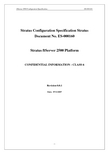
1.7硬盘配臵指南本节定义了ftServer 2500容错服务器磁盘驱动器安装的过程及指南。
1.7.1内部硬盘配臵每个ftServer 2500容错服务器的PCI扩展部分包括一个四Channle/Lane 的SAS控制器,可控制SAS或SATA硬盘。
通道0-2连接至内臵硬盘。
系统每个CPU-I/O模块有内臵3个硬盘托架,可3块安装热插拔的硬盘,每个I/O单元中相同位臵的硬盘托架中的硬盘作镜像保护数据。
注意:所有硬盘应成对且镜像安装。
镜像意味着6块物理硬盘相当于3块逻辑硬盘。
本文档将采用这样的约定:[逻辑/物理]硬盘。
例如:具有6块镜像硬盘的ftServer 2500将标记为[L3/P6]。
下面是内部SAS/SATA硬盘安装的说明。
参阅下表图示的内部硬盘和对应的ID。
当配臵镜像内部硬盘时,参阅显示在硬盘上的SAS通道号。
表18:CPU/IO CRU模块(前视)SAS Channel 2Disk 3 (DXXX)SAS Channel 1Disk 2 (DXXX)SAS Channel 0Disk 1 (DXXX)内部启动盘扫描逻辑系统首先扫描主IO单元上的内部SAS控制器。
在主IO上的3个SAS 通道从通道0开始扫描。
启动盘必须是第一块被扫描的硬盘,如果第一块被扫描的硬盘是数据盘,系统将找不到启动盘。
如果没有发现启动盘,则系统将会进行Fault Resilient Boot(FRB)。
鉴于这个原因,建议启动盘安臵如下:1.要求启动盘安装在最下面的硬盘托架中(SAS通道0);2.启动盘必须使SAS硬盘而不能是SATA硬盘;。
网络机房服务器及网络安全设备安装维护手册
网络机房服务器及网络安全设备安装维护手册1. 介绍1.1 机房服务器和网络安全设备概述本手册旨在提供有关网络机房服务器和网络安全设备的安装、配置和维护的指导。
这些设备对于网络基础设施的性能和安全至关重要。
1.2 目标受众本手册的目标受众包括机房管理员、网络管理员和技术支持人员。
它旨在帮助他们正确地安装、配置和维护这些关键设备,以确保网络的可用性、性能和安全性。
2. 安全须知2.1 电源和电压要求电源要求:确保服务器和网络安全设备的电源满足设备制造商的要求,以避免电源故障导致的损害。
2.2 安全注意事项安全是首要任务。
在安装和维护过程中,始终遵循以下安全注意事项:使用防静电设备,避免静电放电对设备的损害。
在工作时,注意设备的重量和尺寸,以避免受伤。
关闭电源并断开电源线,确保电器设备处于断电状态,然后才进行维护。
2.3 防静电措施防止静电放电:使用防静电手环或防静电地板。
将设备存放在防静电袋中。
3. 安装前准备3.1 机房选址和环境要求选择机房位置:确保机房位置干燥、通风良好,远离水源和潮湿环境。
提供足够的空间,以容纳服务器机架和网络安全设备。
电源和冷却要求:安排稳定的电源供应,使用UPS备电源系统以应对突发停电。
实施有效的空调和温度控制措施,以维持适宜的工作温度。
3.2 电源和冷却系统准备安装UPS系统,确保设备在电源故障时有足够的时间来完成安全关机。
确保空调系统运行正常,维持机房内的稳定温度和湿度。
3.3 数据线和网络连接准备确保提供足够的数据线和网络电缆,以连接服务器和网络安全设备到网络。
4. 服务器安装4.1 机架或机柜准备安装服务器机架或机柜,确保它们坚固、稳定,并正确安装在机房中。
4.2 服务器固定和安装使用合适的工具,将服务器正确安装到机架或机柜中,确保固定稳固。
4.3 电源和数据线连接将服务器的电源线插入电源插座,确保连接牢固。
使用适当的数据线连接服务器到网络设备和交换机。
4.4 服务器开机和基本配置启动服务器并按照制造商的说明进行基本配置,包括设置IP地址、子网掩码、网关等。
4400直埋字体适配器安装说明书

PageБайду номын сангаас1
97864C (Rev. D - 06/16)
4400 Direct Bury Fountain Adapter
PARTS LIST
ITEM NO.
1 2 3 4 5 6
PART NO.
45835C 75617C 75616C 70204C 75611C 70421C
DESCRIPTION
5. After sufficient cure of concrete, remove flange bolts and washers.
6. Mount fountain assembly per instructions supplied with fountain and Items 4, 5, & 6 (See below).
INSTALLATION INSTRUCTIONS
1. Thread nuts (Item 3) onto rods (Item 2) (one nut per rod).
2. Thread rods into adapter cylinder (Item 1) and tighten nuts against cylinder securely.
3. Place washers (Item 6) on bolts (Item 4) (one washer per bolt). Assemble bolts into adapter flange. Thread bolts all the way in.
4. Secure adapter into concrete forms as per Standard Practice and as shown below. Be sure to align adapter for proper location of Water inlet line, Drain line, and required fountain alignment.
ftServer常用操作介绍

Stratus ftServerW2500 W4400 W6200服务器常用操作介绍ftServer服务器简介Stratus ftServer系列服务器,是一种具有99.999+%连续运行时间的标准容错服务器。
该系列服务器使用Intel公司Xeon处理器,融合了Stratus公司二十多年生产容错计算机的技术和经验,消除了集群系统的复杂操作和高成本负担,为Windows环境提供了前所未有的高可靠性连续运行保障。
ftServer服务器拥有无与伦比的性价比,专门用于各种需要高可靠性处理能力和远程管理的业务。
例如服务器整合、企业资讯传送、小型数据库应用、企业资源规划、客户关系管理、供应链管理、实时数据采集等关键业务应用领域。
l ftServer 2500是一款入门级容错服务器,属于ftServer产品线的低档品种,提供客户所需的基本硬件容错特性;具有逻辑1-路双核Xeon处理器,最大支持6GB内存,可支持6个内部SAS 或SATA硬盘,内置2对千兆网口,可运行Windows 2003标准版操作系统或RHEL AS 4(64位)Linux操作系统。
l ftServer 4400是一款部门级容错服务器,属于ftServer产品线的中档品种,提供客户所需的硬件容错特性;它具有1-路或2-路双核Xeon处理器,最大支持12GB内存,可支持6个内部SAS 或SATA硬盘,内置2对千兆网口,可运行Windows 2003企业版操作系统或RHEL AS 4(64位)Linux操作系统。
l ftServer 6200是一款公司级容错服务器,属于ftServer产品线的高档品种,具有高度的灵活性和极强的扩展性。
它具有2-路四核Xeon处理器,最大支持24GB内存,可支持6个内部SAS或SATA硬盘,内置2对千兆网口,扩展方便,性能优异,可运行Windows 2003企业版操作系统或RHEL AS 4(64位)Linux操作系统。
FTTH装维
FTTH装维第一篇:FTTH装维FTTH安装、查修手册目录一、安装流程以及注意事项二、E8-C安装操作规范数据(三个版本)四、E8-C中兴终端自动下发配置(两个版本)和手工填写用户数据(两个版本)五、E8-C贝尔终端自动下发配置和手工填写用户数据六、E8-C基本常见障碍查修七、附录三、E8-C华为终端自动下发配置(三个版本)和手工填写用户一、安装流程以及注意事项打印工单并查看工单上用户名、号码、VLAN号、SN号、设备标识号、纤号、光交位置、备注等信息。
(一)E8-C安装全流程:1:根据工单内容核对用户信息是否准确 2:布放皮线光缆至用户家3:用冷接子或热熔方式在用户家中接续光纤,做好接头4:利用红光源、光功率计等仪表测试光纤通路及衰减5:跳纤,按规范要求布放,根据工单光交位置以及分光器编码和纤芯号跳接光纤,并按标准粘贴标签6:根据业务工单要求,进入光猫填写正确的数据,为客户开通业务,安装客户端软件并简单指导用户如何正确使用7:清理用户装维现场,还原挪移家具,装维下脚料带出用户家8:补录资料中(电子表格)用户家光源位置。
(二)注意事项1、制作快捷头时,注意纤芯不要损伤眼睛。
2、施工完毕必须废纤芯带走,禁止留在用户家中。
3、使用切割刀时,防止沾水、进入灰尘、严禁切割其他物品,使用完毕后,用软物保护刀口。
4、使用红光源时严禁对眼睛直射。
二、E8-C安装操作规范标签粘贴要求:1.标签“中国电信”上沿朝尾纤根部5公分处,面对背胶,将标签“中”字背胶处置于尾纤,折叠标签。
2.标签折叠位置,原则上到宽沿与“信”末对齐,标签对折后,不覆盖“信”字。
跳纤规范:1、跳纤操作必须满足架内整齐、布线美观、便于操作、少占空间的原则。
2、跳纤长度必须掌握在500mm 余长范围内;3、长度不足的跳纤不得使用,不允许使用法兰盘连接两段跳纤4、架内跳纤应确保各处曲率半径大于400mm。
5、跳纤总体原则:下走内、上走外。
6.完成后的效果。
SUN ELECTRIC CORPORATION MCS-2500-4-N产品安装说明书
SUN ELECTRIC CORPORATIONINSTALLATION OVERVIEW:_____________________________________________The Installation Instructions listed are for the various versions of the MCS-2500-4-N. The unit is shipped as a fully assembled unit except for the items as listed in the Parts List. The MCS-2500-4-N is produced for National Accounts and will not have the Software shipped in the unit. It will be shipped in a separate box for the particular customer.PARTS & ACCESSORIES LIST:__________________________________________PART NUMBER DESCRIPTIONQUANTITY0301-0944-01Filter Element, 75 microns 10301-0945-01Filter Element, 8 microns 10403-1311-06Screw, 6-32 x 3/820507-0025-01Probe Assembly 10552-0043Adapter 10552-0044Adapter 10552-0045Adapter10552-0089-01Mouse, three button 10552-0948-01Disk Caddy10552-0959-06Document Booklet 10610-0163Screw, 10AB x 1/240616-0006Keps Nuts, #6-3220647-0170Tee10669-0220Hose, Poly, 1/4” diameter 1.67ft 0669-0623Hose, 1/8 x 5/16 x 610669-0733Hose, 3/16 x 5/16 x 610669-0734Hose, 1/4 x 7/16 x 610692-1834-01SEL 1403C Questionnaire 10718-0103Cable Clamp 10787-0035Cap11091-0303-01Boom Kit11747-0101Pattern Pickup, Chrome 11747-0102HEI Pickup13988-0255-01Exhaust Hose Assembly 16002-0346Lead Assembly 16002-0349Jumper16004-0407Test Lead, Low Temperature1Model:MCS-2500-4-N UNIT SETUP Page:1 of 5Installation InstructionsPART NUMBER DESCRIPTION QUANTITY 6004-0462Volt/Ohm Test Lead, Pink16004-0544-02Pattern, Dual, Assembly, Black16004-0763-02Pattern Lead Conventional, Blue16004-0768-01Cable Assembly, VIP16004-0775-02DIL “Y” Adapter16005-0171-03Amp Probe Assy16005-0182-02Universal Test Lead Assembly16006-0003-02Vacuum Hose17009-1374-08Timing Light Assembly17009-1869-01Exhaust Probe Assembly17009-1921-04Remote Assembly17009-2325-02Trigger Pickup and Lead Assy, Red17009-2334-03Mag Probe, Test Lead17054-0056Adapter, Ford F1 Mag17054-0057Adapter, Chrysler C1 Mag17054-0060Adapter, Ford F2 Mag17054-0062Adapter, Chrysler C2 Mag1EAA0085C06A VIP 1/2 Calibrated Assembly1EAL0123C00A Keyboard Overlay1EASC060C01A Top Panel, Shroud1EASC060C02A Left Side Panel, Shroud1EASC060C03A Right Side Panel, Shroud1 REQUIRED TOOLS:____________________________________________________• Complete Tool Kit• Anti-Static Kit2. After removing the VIP assemblies from the foam packing, remove the carton sides and the topfoam packing.3. If there is no foam collar around the base of the monitor, there will be a two piece cardboard collar inthe packing carton. Insert this collar under and around the base of the monitor to support it during the uncrating process.4. Slide the MCS-2500-4-N and carton base off the pallet. Split the corners of the base carton.5. Lean the MCS-2500-4-N so that one half of the foam base can be removed.6. Lean the MCS-2500-4-N so the other half of the foam base can be removed.7. Remove the two piece cardboard or foam collar from around the base of the monitor.NOTE: It is recommended that this packing be retained in case the unit has to be transported at a later date.8. Open the computer door and remove the cardboard inserted behind it.9. Open the keyboard drawer and remove the bubble wrap taped to the keyboard.10. Pull the printer drawer out and cut the tie wrap holding the bubble wrap. Remove the bubble wrap.11. Lift the Printer Cover and cut the tie wrap holding the Print Head.12. Inventory all items using the appropriate column in the Parts and Accessories Lists and inspect fordamage. The parts are located in the accessories bag in the bottom drawer of the unit.13. Clean the keyboard surface to remove dirt and dust. Peel the backing off the Keyboard Label(EAL0123C00A) and place the label around the Function keys as shown in Figure 1.Figure 1: Keyboard Label14. Install the Boom Kit (1091-0303-01) following the instructions enclosed in the Boom Kit box. Do notinstall the three screws in the rear on the bracket at this time and leave the Boom off.15. Install the Left Side Panel, as viewed from the front (EASC060C02A), using the three screws left outof the Boom. This panel mounts over the Boom bracket. See Figure 2, Page 4.16. Install the Right Panel, as viewed from the front (EASC060C03A), to the cabinet using the two (2) 6-32 x 3/8 screws (0403-1311-06) and the two (2) 6/32 Keps nuts (0616-0006). The screws areinserted from the inside out and the nuts are on the outside of the cabinet. See Figure 2, Page 4. 17. Attach the Top Panel (EASC060C01A) to the side panels using the four (4) 10AB x 1/2 screws(0610-0163). See Figure 2, Page 4.18. Install the Boom into the bracket.REAR VIEWEASC060C03A RIGHT SIDE PANEL (FROM FRONT)EASC060C02ALEFT SIDE PANEL(FROM FRONT)BOOM FIGURE 2: SHROUD19. Install the VIP modules by hooking them onto the end of the boom in the slot provided.20. Connect the female end of the VIP Cable Assembly (6004-0768-01) to the MCS Interface connectoron the VIP 1 Module.21. Connect the male end of the VIP Cable Assembly (6004-0768-01) to the VIP Interface connector onthe rear of the MCS-2500-4-N.22. Connect the Trigger Pickup and Lead Assembly (7009-2325-02) to the Trigger Connector on the VIP1 Module.23. Connect the Conventional, Blue Pattern Lead (6004-0763-02) to the Secondary Connector on theVIP 1 Module.24. Connect the Volt/Ohm Test Lead (6004-0462) to the Volt/Ohm Connector on the VIP 1 Module.25. Connect the Timing Light Assembly (7009-1374-08) to the Timing Connector on the VIP 2 Module.26. Connect the Vacuum Hose (6006-0003-02) to the vacuum port on the VIP 2 Module.27. Connect the Low Temperature Test Lead (6004-0407) to the Temperature Connector on the VIP-2Module.28. Connect the Amp Probe Assembly (6005-0171-03) to the Amps Connector of the VIP 2 Module.29. Connect the Remote Control Assembly (7009-1921-04) to the Remote Connector on the rear of theunit.30. Place the remaining accessories in the storage drawer of the MCS-2500-4-N.SOFTWARE INSTALLATION:____________________________________________ 1. Follow the Installation Instructions packaged with the Enhancement Kit.CALIBRATION:________________________________________________________1. From the MCS menu select #1 VIP.2. Allow unit to warm-up and verify that all items on the calibration page are all green. If not go toTroubleshooting3. Follow the procedure in chapter 15 of the MCS-2500 Service Manual, perform a full hardware andsoftware calibration of the IR Bench.4. Exit to the Main Menu.TROUBLESHOOTING SECTION:_________________________________________ COMPLAINT CORRECTIVE ACTIONI. Amps, Vacuum and OilTemperature are Black 1. Vip 2 may not be installed. Press <Continue>, from theCalibration page.2. Select number 6(utils) from the Menu.3. Select number 7 (Options).4. Verify that the VIP 2 is installed. The button should be White. Ifit is not then select <VIP2 INSTALLED>.5. Press <CONTINUE> choose Status from the menu thenCalibration to make sure that Amps, Vacuum and OilTemperature calibrate.6. If not refer to the Troubleshooting Section in the MCS-2500Service Manual.PLACE THESE INSTALLATION INSTRUCTIONS IN THE SERVICE MANUAL FOR THE MCS-2500INSTALLATION COMPLETE。
- 1、下载文档前请自行甄别文档内容的完整性,平台不提供额外的编辑、内容补充、找答案等附加服务。
- 2、"仅部分预览"的文档,不可在线预览部分如存在完整性等问题,可反馈申请退款(可完整预览的文档不适用该条件!)。
- 3、如文档侵犯您的权益,请联系客服反馈,我们会尽快为您处理(人工客服工作时间:9:00-18:30)。
Stratus ftServer W2500 W4400 W6200服务器安装步骤安装前的场地准备事项l机柜— ftServer容错服务器有机架式(Rack Mounted)和塔式(Pedestal)两种,如果用户购买的是机架式服务器,那么需要事先准备好一个机柜。
这个机柜必须19英寸宽,并符合EIA 310-D 标准。
机柜通常条件是19英寸宽、40英寸深、前架与前门的距离为3英寸以上,后架与后门的距离为6英寸以上,前后架的间距为24.5至30英寸之间,机柜内有良好的空气循环条件,通常柜顶安装有排风风扇,对机柜高度没有要求,但机柜中至少有4U以上的空间供ftServer安装。
机柜后部应事先安装好两路PDU(电源接线板)。
l显示器、键盘鼠标—如果用户没有从Stratus购买显示器或键盘鼠标,应事先准备好这些外部设备。
显示器必须有15针的D-sub接头;键盘和鼠标都是USB接口;l电源— ftServer服务器需要使用两路电源;为保证服务器的安全运行,建议至少其中的一路使用UPS输出的电源;整个ftServer 2500、4400、6200服务器的运行功率大约在1000瓦至1500瓦之间,输入电源要求为200-240VAC,50-60Hz。
l场地—容错服务器通常被用于关键业务的处理,一般不会定期关机,所以其运行场地必须保持干净整洁(符合ISO14644-1 class 8标准),并具有良好的光线,以便工作人员观察服务器上的各种指示灯;机柜前后应有一定的空间,供工作人员打开机柜门进行操作;机房的温度应保持在5℃至35℃之间,相对湿度应保持在8%至80%之间。
l网线— ftServer服务器有4个内置RJ45接口的1000M以太网端口,通常会组成两个虚拟的网卡,实现容错功能的对外联络;用户应根据自己的使用情况,需要准备好相应的网线和交换机端口。
如果用户购买了VTM部件,该部件也有两个100M以太网口,可供用户对服务器进行内部管理,用户也需要准备好相应的网线和交换机端口。
l电话线—如果用户购买了Stratus的远程服务,就需要事先准备好一条电话线,供连接和设置ASN使用。
ASN可以将服务器内部的硬件故障上报给Stratus的服务响应中心,Stratus的维护服务工程师也可以通过ASN远程连接进入客户的ftServer服务器,进行诊断和处理;(因Stratus 中国服务响应中心位于上海市,所有非上海市的用户,需要开通这条电话线的国内长途功能。
)拆除包装箱用户收到ftServer服务器包装箱后,应该首先查看包装箱的标签,看是否与你所购买的物件相符;通过检查包装箱上的防震和防倾斜标志是否完好,可以判断出物件的运输是否存在问题;将服务器包装箱防止在一个空阔河便于拆箱的地方,用剪刀剪断包装箱上的捆扎带(注意:防止捆扎带伤人),打开包装箱的上盖;依次取出包装箱中的部件和附件盒。
清点所有的部件与你所购买的物件是否相符;服务器上机架和部件组装机架式服务器的机架安装入柜如果你购买的机架式ftServer服务器,需要首先在机架上确定安装位置。
ftServer服务器需要占用4U 的空间,如果你有其它附件,需要另外安排空间,如KVM占用1U空间,每个PDU也占用1U空间。
通常我们将PDU(电源分配单元,即电源接线板)放置在机柜的最下面位置,然后依次向上放置存储设备、服务器。
键盘鼠标、显示器或KVM要放置在适当的位置,以便于操作使用。
后架的定位见下左图(从下往上数,第2U的最下洞眼,第3U的最上面洞眼作标记)前架的定位键下右图(从下往上数,第2U的下面两个洞眼和第4U的下面两个洞眼,填上机架螺母)(后架定位图)(前架定位图)用圆头螺丝(自带垫圈)将两块机架的插板分别固定在后架的两边(见下图),插板上预留一颗平头螺丝(最上面一排)以备后用。
两人配合,抬起服务器机架放入机柜,并将已经安装好的后架两块插板分别插入服务器机架的两边;注意:将插板上预留的左右各一颗导向螺丝插入机架的导向槽中,以便借力。
(见下图)在机柜前方,将服务器机架本身的固定栓插入机柜前架的相应洞眼中,然后两边各用2棵大平头螺丝(加垫圈)拧入第2U和第4U最下面洞眼的机架螺母中;将两边各4颗固定螺丝,经机架导向槽,拧入机架插板的相应位置。
机架固定完成。
(见下图)机箱安装依次取出包装箱里的两个CPU-IO机箱,将其插入服务器机架中。
注意,如果你从Stratus购买了Windows/Redhat操作系统,有一个硬盘上有“Boot”字样的标签,这是预装系统的标志,请将这个CPU-IO机箱放置在机架式服务器的上面位置,或者是塔式服务器的左面位置。
连接外设和电源将键盘、鼠标和显示器连接到服务器背后的相应端口上,然后分别连接服务器的两个电源(建议至少其中一个电源使用UPS的输出电源)。
连接电源前,应检查电源是否符合要求(200-240VAC,50-60Hz).如果用户购买了存储设备,建议仅在服务器中安装好HBA卡,但是先不要连接电缆到存储设备;等服务器操作系统和容错软件都正常安装完毕后,再连接电缆到存储设备上;电源接通后,服务器两个机箱的电源按钮中的其中一个会亮灯,另一个按钮是不亮灯的。
安装前的资料准备开始做IPL或Post-IPL工作前,请先准备好以下系统参数资料:参数描述Regional Setting 时区设置,涉及到语言和其他一些默认设置的改变,例如:日期、时间、数字、货币符号以及本地语言输入法等等;User name and organization 服务器安装者所属的组织和用户名(系统后面安装的许多软件会自动使用这些信息)Microsoft Product Key 微软操作系统得许可证号;如果你从Stratus购买了操作系统,相关的版权标签已经被贴在了服务器机架的内侧;如果你自己购买了操作系统,请在相应的包装上寻找;Licensing mode 许可证方式;默认方式“Per Server”要求每一个连接到服务器的客户连接都有一个客户访问许可证,这种方式可以转变成另一种许可证方式,即“PerDevice or Per User”方式,它是指每个访问服务器的计算机都要求有一个单独的客户访问许可证,这种方式不能转变为“Per Server”。
System name and Administrator password 系统名是指计算机在系统中的名称,将在组或域中使用。
系统管理员的口令是服务器系统一个十分重要的安全保障。
Date and timesetting当前的日期、时间和所使用的时区信息。
Networking setting 服务器需要设置的网络参数,包括IP地址、掩码、网关地址以及DNS地址等等,你也可以设置使用DHCP获得这些信息。
Workgroup or Computer Domain 服务器将要加入的组或域,两者必选其一。
组是将一些计算机组成小组,分享某些资源;域是通过一些系统设置,将许多计算机组织、分工,以充分利用目录数据库、共享资源等;(建议在安装时,暂时将服务器设置为默认的组)操作系统和容错软件的安装注意事项l如果你从Stratus购买了操作系统,ftServer服务器出厂前已经被预装了操作系统,你只需要从下面的步骤“Mini-Setup”开始,依次向下执行步骤。
如果你自己购买的操作系统,ftServer服务器出厂前没有预装操作系统,你需要执行下面的所有步骤。
l Windows 2003企业版仅能安装于ftServer4400和6200服务器;Windows 2003标准版能安装于ftServer2500、4400和6200服务器。
l Stratus预装的Windows2003系统中,已经安装了SP2补丁;有关R2的增强选项已被载入系统,但没有被安装,你可以使用“控制面板”里的“添加或删除程序”来安装R2的增强选项。
l安装完操作系统和容错软件后,系统的启动盘还没有做镜像;请在尽块完成系统盘的镜像以确保系统容错性能的实现;l如果你要安装64位的Windows 2003操作系统并要使用中文,必须先用英语安装完64位的Windows 2003操作系统,然后再使用多语言用户界面(MUI)DVD安装相关的支持包;l系统安装完毕后,会自动生成两个报告,具体的路径为:C:\Program Files\FTSYS\Customer Service\VersionReports和C:\Program Files\FTSYS\Customer Service\InstallCheck安装介质的确认l Windows 2003标准版或企业版的DVD,如果其不包含SP2,请另外准备好SP2的DVD。
l ftServer系统软件的DVD,版本是5.1.0.x(64位或32位取决于你要安装的Windows 2003) l StrataDOC光盘服务器安装前的检查l检查并确认服务器已经连接好电源、显示器、键盘和鼠标;l如果你购买有存储设备,确认服务器至存储设备的连接已经被断开;l确认需要安装操作系统的硬盘,被安置于10号机箱(机架式服务器的上面那个机箱)的0号硬盘插槽,并且10号机箱的电源按钮灯已经亮了。
请先暂时拔出服务器中其余所有硬盘,待系统安装完成后再逐一插回服务器;l打开显示器电源;然后按下10号机箱上的电源按钮,系统开始启动;l将ftServer容错软件的第1张DVD光盘放入10号机箱的DVD驱动器,用于系统启动;l系统启动并且屏幕出现画面时,按F2进入系统BIOS菜单;修改BIOS参数l按下F2后,系统会进入BIOS设置菜单;l进入“Server”页面,选“Monitoring Configuration”项,按回车;l将“OS Boot Monitoring”项改为“Disable”;(用上下方向键)l将“Option ROM Scan Monitoring”项改为“Disable”;l按F10保存修改并退出BIOS设置;IPL –系统软件的初始化安装l系统开始启动,过几分钟后会出现信息“Server Software Initial Program Load for the Windows Operating System”,然后出现XP的闪动画面(接着可能会出现一个黑屏和蓝屏,但是没有字符,不必介意);l几分钟后,屏幕出现“ftSys”字样,然后出现“Start ftServer System Software IPL”对话框,选择默认项“Run the ftServer System Software Release 5.1.x.x Initial Program Load”,并点击“Next”按钮;l出现提示,选择IPL要创建的分区尺寸,用于安装Windows操作系统和容错软件(即所谓的C:盘);( 如果安装硬盘上已经有分区,则系统会出现提示;然后选择安装分区,该分区将被格式化后用于操作系统和容错软件的安装)l出现提示,更换相应光盘。
