Manufacturing Tool User's Manual
EVAL-M1-099M-C User Manual

AN2017-18 EVAL-M1-099M-C User ManualEVAL-M1-099M-C User ManualiMOTION™ Modular Application Design KitAbout this documentScope and purposeThis application note provides an overview of the evaluation board EVAL-M1-099M including its main features, key data, pin assignments and mechanical dimensions.EVAL-M1-099M is an evaluation-board as part of the iMOTION™ Modular Application Design Kit Platform. This board features and demonstrates Infineon’s advanced Motion Control Engine (MCE) technology for permanent magnet motors drive over the full speed range.The evaluation board EVAL-M1-099M was developed to support customers during their first steps designing applications with running any permanent magnet motor via sensorless sinusoidal control.Important Note: EVAL-M1-099M-C is the orderable part number for the kit which contains only EVAL-M1-099M MADK Control Board. In order to program, configure and debug the motor control systems based on EVAL-M1-099M, an Isolated Debugger Tool MCETOOLV2 is required. MCETOOLV2 is not part of the EVAL-M1-099M-C kit and needs to be ordered separately.Intended audienceThis application note is intended for all technical specialists who know motor control and high powerelectronics converter and this board is intended to be used under laboratory conditions.Table of ContentsAbout this document (1)Table of Contents (1)1Safety precautions (2)2Introduction (3)3Main features (4)3.1Key data (5)3.2IRMCK099 installer (8)4Pin assignments (9)5Schematics and Layout (11)5.1Schematic Overview (11)5.2Current feedback (12)5.3AD port Input (13)5.4PCB Layout (14)6Bill of Materials of EVAL-M1-099M (17)7Reference (19)Revision History (20)Safety precautions1 Safety precautionsIn addition to the precautions listed throughout this manual, please read and understand the following statements regarding hazards associated with development systems. Table 1PrecautionsAttention: The ground potential of the EVAL-M1-099M system is biased to a negativeDC bus voltage potential. When measuring voltage waveform by oscilloscope, the scope’s ground needs to be isolated. Failurdeath and equipment damageAttention: Only personnel familiar with the drive and associated machinery should plan or implement the installation, start-up and subsequent maintenance of the system. Failure to comply may result in personal injury and/or equipment damage.Attention: The surfaces of the drive may become hot, which may cause injury.Attention: Electrostatic installing, result electrostatic guidelines.Attention: damage sizing the motor, supplying an incorrect or inadequate DC supply or excessive ambient temperatures may result in system malfunction.Attention: Remove or connect this control board from or to the power drive. Wait three minutes after removing power from the power drive to discharge the bus capacitors. Do not attempt to service the drive until the bus capacitors have discharged to zero. Failure to do so may result in personal injury or death.Attention: removed unnecessary for system installation may result in overheating or abnormal operating condition.Introduction2IntroductionThe EVAL-M1-099M evaluation board is a part of the iMOTION™ Modular Appli cation Design Kit for drives (iMOTION™ MADK). In order to run a motor, the mating power board is required to interface this evaluation board.The MADK platform is intended to use various power stages with different control boards. These boards can easily be interfaced through the 20 pins iMOTION™ MADK-M1 or the 30 pins iMOTION™ MADK-M3 interface connector. This board is equipped with 20 pins connector and for motor control only.This evaluation board is designed to give comprehensible solutions of sensorless control of permanent magnet motors over the full speed range. It consists of IRMCK099M Motor Control IC, capable of 3-phase and three types of 2-phase modulation, JTAG and UART interface which are isolated via opto-isolation box (MCETOOLV2), and needs a single 3.3V supply. Required Isolation Box MCETOOLV2 is not part of the EVAL-M1-099M-C kit and needs to be ordered separately. For details of the isolation box please refer to its Application Note.The EVAL-M1-099M evaluation board is available from Infineon and its distribution partners. The features of this board are described in the design feature chapter of this document, whereas the remaining paragraphs provide information to enable the customers to copy, modify and qualify the design for production according to their own specific requirements.Environmental conditions were considered in the design of the EVAL-M1-099M. The design was tested as described in this document but not qualified regarding safety requirements or manufacturing and operation over the whole operating temperature range or lifetime. The boards provided by Infineon are subject to functional testing only.Evaluation boards are not subject to the same procedures as regular products regarding Returned Material Analysis (RMA), Process Change Notification (PCN) and Product Discontinuation (PD). Evaluation boards are intended to be used under laboratory conditions by technical specialists only.Figure 1 shows the evaluation board EVAL-M1-099M. This document explains the features and details of this board as well as control IC which is IRMCK099.Figure 1Evaluation board EVAL-M1-099M3Main featuresEVAL-M1-099M is a control evaluation board for motor control application. The kit demonstrates Infineon’s motion control IC technology.Main features of Motion Control IC are:•MCE (Motion Control Engine) - Dedicated computation engine for high efficiency sinusoidal sensorless motor control•Supports both interior and surface permanent magnet motor•Built-in hardware for single or leg shunt current feedback reconstruction•Loss minimization Space Vector PWM•Two-channel analog output•JTAG programming port for emulation/ debugger•Serial communication interface (UART)•Internal 16 Kbyte OTP memory•Multiple motor parameter support• 3.3V single power supply•V SP control mode•PG output•Internal temperature sensing•External NTC thermistor from power board temperature sensing support.The evaluation board characteristics are:•Complete kit for running any permanent magnet motor via sensorless sinusoidal control• 3.3V single power supply•JTAG and UART interface, isolated via opto-isolation box•Capable of 3-phase and three types of 2-phase modulation•RoHS complaint•PCB is 45 x 45 mm and has two layers with 35 μm copper each3.1Key dataFigure 2 shows a typical motor control application block diagram using the IRMCK099. The IRMCK099 provides a built-in closed loop sensorless control algorithm using the unique flexible Motion Control Engine (MCE) for permanent magnet motors. The MCE™consists of a collection of control elements, motion peripherals, a dedicated motion control sequencer and internal memory to map internal signal nodes. IRMCK099 also employs a unique single shunt current reconstruction circuit in addition to two leg shunt current sensing circuitFigure 3 indicates pinout of IRMCK099. IRMCK099 contains 16 Kbytes of OTP program memory and comes in a compact 5mm x 5mm 32-pin QFN package.Figure 3Pinout of IRMCK099Table 2 depicts the important specifications of the evaluation board EVAL-M1-099M.Table 2Eval-M1-099M board specifications3.2 IRMCK099 installerIn order to run this evaluation board, the user has to download iMOTION™ installer from Infineon iMOTION TM Web, it contains information about all the iMOTION™ control IC including IRMCK099 development software at Infineon web.To download supporting software, pls goes to /imotion-software . And all the updated version software is saved there.Note: Currently, the user can download V02_01 and the patch file. See below link. Or user can open below link to download IRMCK099 Installer V02_01 package./dgdl/Infineon-99serieskitmceinstaller-SW-v02_01-EN.exe?fileId=5546d46253f65057015437c4a4e44339And download V2.1 Patch Kit to update the install package. Then overwrite installed demo project. /dgdl/Infineon-99+Series+V2_1+Patch+Kit-SW-v02_01-EN.zip?fileId=5546d46256fb43b30157034e5b754664Figure 4 the functional groups of the EVAL-M1-099M evaluation board.Figure 4Functional groups of the EVAL-M1-099M evaluation board’s top side1234561. UART Connecter (J2)2. JTAG Connecter (J1)3. Test Signal Pin Connecter (J5)4. iMOTION ™ MADK-M1 20 pinsinterface connector for power board(J3)5. Test Signal Pin Connecter (J4)6. MCE -control IC (U1)4 Pin assignmentsGeneral information about the connectors of the Eval-M1-099M evaluation board is described below.Table 3 and Table 4 include the details of JTAG and UART connectors.Table 4J2-JTAG ConnectorTable 5 provides the pin assignments of the iMOTION™MADK-M1 20 pins interface connector J3. This connector is the interface to the power board.Table 5J3- iMOTION™MADK-M1 20 pins interface connector for power boardTable 6 and Table 7 include the details of test signal pin connectors. Table 6Test signals pin5Schematics and LayoutTo meet individual customer requirements and make the EVAL-M1-099M evaluation board a basis for development or modification, all necessary technical data like schematics, layout and components are included in this chapter.5.1Schematic OverviewFigure 5 shows the schematic of EVAL-M1-099M evaluation board with IRMCK099 controller.Figure 5The schematics for the Eval-M1-099M evaluation board5.2Current feedbackCurrent Feedback Gain—the control on this board has an internal current feedback amplifier which has default gain. The user can use this gain to count the current sensing range and Internal Itrip. An example is shown in Figure 6. The sample resister is 0.25Ω.R17=R13∗1.5,R16=R13∗3When input = 0V, IFBO = 601mVCurrent Feedback Gain =R13R14=7.68K5.9K=1.302Current sensing range is depending on current sample resister.Current sensing range=0.599Current Gain∗Sample resisterCurrent sensing range=0.5991.302∗0.25Ω=1.84AThe part of protect circuit, when using single shunt: Iu current feedback OPAMP internal Itrip can protect overcurrent if the system response designed as demand.Internal Itrip=IC maximum specification Itrip level − 0.601VCurrent Gain∗ Sample registerInternal Itrip=1.306V−0.601V1.302∗0.25Ω=2.17AWhen using leg shunt. The gate kill signal from power module works. That is protected by outside IRMCK099. When using single shunt. IV+ and IV- connect GND.Figure 6 depicts the Eval-M1-099M evaluation board is suitable for single shunt and leg shunt for current feedback.Figure 6The part of Current feedback on the Eval-M1-099M evaluation board5.3AD port InputFigure 7 depicts AD input for IRMCK099. Temperature input should fit to the design recommendation in the IRMCK099 application note.Figure 7AD input on the Eval-M1-099M evaluation board5.4PCB LayoutThe layout of this board can be used for different voltage or power classes of power board. The PCB has two electrical layers with 35µm copper by default and its size is 45 mm × 45 mm. The PCB board thickness is 1.6mm. Get in contact with our technical support team to get more detailed information and the latest Gerber-files. Figure 8 illustrates the top assembly print of the evaluation board.Figure 8 Top overlay print of the EVAL-M1-099M evaluation boardFigure 9 depicts the bottom assembly print of the evaluation board.Figure 9Bottom overlay print of the EVAL-M1-099M evaluation board The top layer routing of the PCB is provided in the following Figure 10.Figure 10Top layer routing of the EVAL-M1-099MFigure 11 illustrates the bottom layer routing of the PCB.Figure 11Bottom layer routing of the EVAL-M1-099M6Bill of Materials of EVAL-M1-099M Table 8 provides the complete bill of materials for the EVAL-M1-099M board.Reference7Reference[1] Datasheet of Infineon IRMCK099M[2] IRMCx100 Reference Manual[3] IRMCx100 Software Developer’s Guide[4] IRMCx100 System Overview[5] Application Note of AN2016-24 for EVAL-M1-05-65D power board, is available for download on Infineon’s website[6] MCETOOLV2 user manual, is available on Infineon website.Note1: Above all reference materials are available for download on Infineon’s website Revision HistoryRevision HistoryMajor changes since the last revisionTrademarks of Infineon Technologies AG AURIX™, C166™, CanPAK™, CIPOS™, CoolGaN™, CoolMOS™, CoolSET™, CoolSiC™, CORECONTROL™, CROSSAVE™, DAVE™, DI -POL™, DrBlade™, EasyPIM™, EconoBRIDGE™, EconoDUAL™, EconoPACK™, EconoPIM™, EiceDRIVER™, eupec™, FCOS™, HITFET™, HybridPACK™, Infineon™, ISOFACE™, IsoPACK™, i-Wafer™, MIPAQ™, ModSTACK™, my -d™, NovalithIC™, OmniTune™, OPTIGA™, OptiMOS™, ORIGA™, POWERCODE™, PRIMARION™, PrimePACK™, PrimeSTACK™, PROFET™, PRO -SIL™, RASIC™, REAL3™, ReverSave™, SatRIC™, SIEGET™, SIPMOS™, SmartLEWIS™, SOLID FLASH™, SPOC™, TEMPFET™, thinQ!™, TRENCHSTOP™, TriCore™. Trademarks updated August 2015Other Trademarks All referenced product or service names and trademarks are the property of their respective owners.Edition <2017-08-21>AN2017-18 EVAL-M1-099M-C User Manual Published by Infineon Technologies AG 81726 Munich, Germany © 2017 Infineon Technologies AG. All Rights Reserved. Do you have a question about this document? Email: ******************** Document reference IMPORTANT NOTICE The information contained in this application note is given as a hint for the implementation of the product only and shall in no event be regarded as a description or warranty of a certain functionality, condition or quality of the product. Before implementation of the product, the recipient of this application note must verify any function and other technical information given herein in the real application. Infineon Technologies hereby disclaims any and all warranties and liabilities of any kind (including without limitation warranties of non-infringement of intellectual property rights of any third party) with respect to any and all information given in this application note. The data contained in this document is exclusively intended for technically trained staff. It is the responsibility of customer’s technical departments to evaluate the suitability of the product for the intended application and the completeness of the product information given in this document with respect to such application.For further information on the product, technology, delivery terms and conditions and prices please contact your nearest Infineon Technologies office ( ). Please note that this product is not qualified according to the AEC Q100 or AEC Q101 documents of the Automotive Electronics Council. WARNINGS Due to technical requirements products may contain dangerous substances. For information on the types in question please contact your nearest Infineon Technologies office. Except as otherwise explicitly approved by Infineon Technologies in a written document signed by authorized representatives of Infineon Technologies, Infineon Technologies’ products may not be used in any applications where a failure of the product or any consequences of the use thereof can reasonably be expected to result in personal injury.Mouser ElectronicsAuthorized DistributorClick to View Pricing, Inventory, Delivery & Lifecycle Information:I nfineon:EVALM1099MCTOBO1。
KR425H-16 Encoder Modulator 用户手册说明书

Cle25H-16 Encoder Modualtor User Manual
1.3 Specifications
Input Video Audio Multiplexing Scrambling
Modulation
16 CVBS inputs , RCA interface , 1 DVB-C Tuner for remux, F type interface (only for DVB-C RF out) 128 IP input over UDP and RTP, DATA1 and DATA2,RJ45
Encoding Bit-rate Rate Control GOP Structure Advanced Pretreatment Encoding Sampling rate Resolution Bit-rate Maximum PID Remapping
Disclaimer
No part of this document may be reproduced in any form without the written permission of the copyright owner. The contents of this document are subject to revision without notice due to continued progress in methodology, design and manufacturing. ClearView shall have no liability for any error or damage of any kind resulting from the use of this document.
NXP SCM-i.MX 6 Series Yocto Linux 用户指南说明书
© 2017 NXP B.V.SCM-i.MX 6 Series Yocto Linux User'sGuide1. IntroductionThe NXP SCM Linux BSP (Board Support Package) leverages the existing i.MX 6 Linux BSP release L4.1.15-2.0.0. The i.MX Linux BSP is a collection of binary files, source code, and support files that can be used to create a U-Boot bootloader, a Linux kernel image, and a root file system. The Yocto Project is the framework of choice to build the images described in this document, although other methods can be also used.The purpose of this document is to explain how to build an image and install the Linux BSP using the Yocto Project build environment on the SCM-i.MX 6Dual/Quad Quick Start (QWKS) board and the SCM-i.MX 6SoloX Evaluation Board (EVB). This release supports these SCM-i.MX 6 Series boards:• Quick Start Board for SCM-i.MX 6Dual/6Quad (QWKS-SCMIMX6DQ)• Evaluation Board for SCM-i.MX 6SoloX (EVB-SCMIMX6SX)NXP Semiconductors Document Number: SCMIMX6LRNUGUser's GuideRev. L4.1.15-2.0.0-ga , 04/2017Contents1. Introduction........................................................................ 1 1.1. Supporting documents ............................................ 22. Enabling Linux OS for SCM-i.MX 6Dual/6Quad/SoloX .. 2 2.1. Host setup ............................................................... 2 2.2. Host packages ......................................................... 23.Building Linux OS for SCM i.MX platforms .................... 3 3.1. Setting up the Repo utility ...................................... 3 3.2. Installing Yocto Project layers ................................ 3 3.3. Building the Yocto image ....................................... 4 3.4. Choosing a graphical back end ............................... 4 4. Deploying the image .......................................................... 5 4.1. Flashing the SD card image .................................... 5 4.2. MFGTool (Manufacturing Tool) ............................ 6 5. Specifying displays ............................................................ 6 6. Reset and boot switch configuration .................................. 7 6.1. Boot switch settings for QWKS SCM-i.MX 6D/Q . 7 6.2. Boot switch settings for EVB SCM-i.MX 6SoloX . 8 7. SCM uboot and kernel repos .............................................. 8 8. References.......................................................................... 8 9.Revision history (9)Enabling Linux OS for SCM-i.MX 6Dual/6Quad/SoloX1.1. Supporting documentsThese documents provide additional information and can be found at the NXP webpage (L4.1.15-2.0.0_LINUX_DOCS):•i.MX Linux® Release Notes—Provides the release information.•i.MX Linux® User's Guide—Contains the information on installing the U-Boot and Linux OS and using the i.MX-specific features.•i.MX Yocto Project User's Guide—Contains the instructions for setting up and building the Linux OS in the Yocto Project.•i.MX Linux®Reference Manual—Contains the information about the Linux drivers for i.MX.•i.MX BSP Porting Guide—Contains the instructions to port the BSP to a new board.These quick start guides contain basic information about the board and its setup:•QWKS board for SCM-i.MX 6D/Q Quick Start Guide•Evaluation board for SCM-i.MX 6SoloX Quick Start Guide2. Enabling Linux OS for SCM-i.MX 6Dual/6Quad/SoloXThis section describes how to obtain the SCM-related build environment for Yocto. This assumes that you are familiar with the standard i.MX Yocto Linux OS BSP environment and build process. If you are not familiar with this process, see the NXP Yocto Project User’s Guide (available at L4.1.15-2.0.0_LINUX_DOCS).2.1. Host setupTo get the Yocto Project expected behavior on a Linux OS host machine, install the packages and utilities described below. The hard disk space required on the host machine is an important consideration. For example, when building on a machine running Ubuntu, the minimum hard disk space required is about 50 GB for the X11 backend. It is recommended that at least 120 GB is provided, which is enough to compile any backend.The minimum recommended Ubuntu version is 14.04, but the builds for dizzy work on 12.04 (or later). Earlier versions may cause the Yocto Project build setup to fail, because it requires python versions only available on Ubuntu 12.04 (or later). See the Yocto Project reference manual for more information.2.2. Host packagesThe Yocto Project build requires that the packages documented under the Yocto Project are installed for the build. Visit the Yocto Project Quick Start at /docs/current/yocto-project-qs/yocto-project-qs.html and check for the packages that must be installed on your build machine.The essential Yocto Project host packages are:$ sudo apt-get install gawk wget git-core diffstat unzip texinfo gcc-multilib build-essential chrpath socat libsdl1.2-devThe i.MX layers’ host packages for the Ubuntu 12.04 (or 14.04) host setup are:$ sudo apt-get install libsdl1.2-dev xterm sed cvs subversion coreutils texi2html docbook-utils python-pysqlite2 help2man make gcc g++ desktop-file-utils libgl1-mesa-dev libglu1-mesa-dev mercurial autoconf automake groff curl lzop asciidocThe i.MX layers’ host packages for the Ubuntu 12.04 host setup are:$ sudo apt-get install uboot-mkimageThe i.MX layers’ host packages for the Ubuntu 14.04 host s etup are:$ sudo apt-get install u-boot-toolsThe configuration tool uses the default version of grep that is on your build machine. If there is a different version of grep in your path, it may cause the builds to fail. One workaround is to rename the special versi on to something not containing “grep”.3. Building Linux OS for SCM i.MX platforms3.1. Setting up the Repo utilityRepo is a tool built on top of GIT, which makes it easier to manage projects that contain multiple repositories that do not have to be on the same server. Repo complements the layered nature of the Yocto Project very well, making it easier for customers to add their own layers to the BSP.To install the Repo utility, perform these steps:1.Create a bin folder in the home directory.$ mkdir ~/bin (this step may not be needed if the bin folder already exists)$ curl /git-repo-downloads/repo > ~/bin/repo$ chmod a+x ~/bin/repo2.Add this line to the .bashrc file to ensure that the ~/bin folder is in your PATH variable:$ export PATH=~/bin:$PATH3.2. Installing Yocto Project layersAll the SCM-related changes are collected in the new meta-nxp-imx-scm layer, which is obtained through the Repo sync pointing to the corresponding scm-imx branch.Make sure that GIT is set up properly with these commands:$ git config --global "Your Name"$ git config --global user.email "Your Email"$ git config --listThe NXP Yocto Project BSP Release directory contains the sources directory, which contains the recipes used to build, one (or more) build directories, and a set of scripts used to set up the environment. The recipes used to build the project come from both the community and NXP. The Yocto Project layers are downloaded to the sources directory. This sets up the recipes that are used to build the project. The following code snippets show how to set up the SCM L4.1.15-2.0.0_ga Yocto environment for the SCM-i.MX 6 QWKS board and the evaluation board. In this example, a directory called fsl-arm-yocto-bsp is created for the project. Any name can be used instead of this.Building Linux OS for SCM i.MX platforms3.2.1. SCM-i.MX 6D/Q quick start board$ mkdir fsl-arm-yocto-bsp$ cd fsl-arm-yocto-bsp$ repo init -u git:///imx/fsl-arm-yocto-bsp.git -b imx-4.1-krogoth -m scm-imx-4.1.15-2.0.0.xml$ repo sync3.2.2. SCM-i.MX 6SoloX evaluation board$ mkdir my-evb_6sxscm-yocto-bsp$ cd my-evb_6sxscm-yocto-bsp$ repo init -u git:///imx/fsl-arm-yocto-bsp.git -b imx-4.1-krogoth -m scm-imx-4.1.15-2.0.0.xml$ repo sync3.3. Building the Yocto imageNote that the quick start board for SCM-i.MX 6D/Q and the evaluation board for SCM-i.MX 6SoloX are commercially available with a 1 GB LPDDR2 PoP memory configuration.This release supports the imx6dqscm-1gb-qwks, imx6dqscm-1gb-qwks-rev3, and imx6sxscm-1gb-evb. Set the machine configuration in MACHINE= in the following section.3.3.1. Choosing a machineChoose the machine configuration that matches your reference board.•imx6dqscm-1gb-qwks (QWKS board for SCM-i.MX 6DQ with 1 GB LPDDR2 PoP)•imx6dqscm-1gb-qwks-rev3 (QWKS board Rev C for SCM-i.MX 6DQ with 1GB LPDDR2 PoP) •imx6sxscm-1gb-evb (EVB for SCM-i.MX 6SX with 1 GB LPDDR2 PoP)3.4. Choosing a graphical back endBefore the setup, choose a graphical back end. The default is X11.Choose one of these graphical back ends:•X11•Wayland: using the Weston compositor•XWayland•FrameBufferSpecify the machine configuration for each graphical back end.The following are examples of building the Yocto image for each back end using the QWKS board for SCM-i.MX 6D/Q and the evaluation board for SCM-i.MX 6SoloX. Do not forget to replace the machine configuration with what matches your reference board.3.4.1. X11 image on QWKS board Rev C for SCM-i.MX 6D/Q$ DISTRO=fsl-imx-x11 imx6dqscm-1gb-qwks-rev3 source fsl-setup-release.sh -b build-x11$ bitbake fsl-image-gui3.4.2. FrameBuffer image on evaluation board for SCM-i.MX 6SX$ DISTRO=fsl-imx-fb MACHINE=imx6sxscm-1gb-evb source fsl-setup-release.sh –b build-fb-evb_6sxscm$ bitbake fsl-image-qt53.4.3. XWayland image on QWKS board for SCM-i.MX 6D/Q$ DISTRO=fsl-imx-xwayland MACHINE=imx6dqscm-1gb-qwks source fsl-setup-release.sh –b build-xwayland$ bitbake fsl-image-gui3.4.4. Wayland image on QWKS board for SCM-i.MX 6D/Q$ DISTRO=fsl-imx-wayland MACHINE=imx6dqscm-1gb-qwks source fsl-setup-release.sh -b build-wayland$ bitbake fsl-image-qt5The fsl-setup-release script installs the meta-fsl-bsp-release layer and configures theDISTRO_FEATURES required to choose the graphical back end. The –b parameter specifies the build directory target. In this build directory, the conf directory that contains the local.conf file is created from the setup where the MACHINE and DISTRO_FEATURES are set. The meta-fslbsp-release layer is added into the bblayer.conf file in the conf directory under the build directory specified by the –e parameter.4. Deploying the imageAfter the build is complete, the created image resides in the <build directory>/tmp/deploy/images directory. The image is (for the most part) specific to the machine set in the environment setup. Each image build creates the U-Boot, kernel, and image type based on the IMAGE_FSTYPES defined in the machine configuration file. Most machine configurations provide the SD card image (.sdcard), ext4, and tar.bz2. The ext4 is the root file system only. The .sdcard image contains the U-Boot, kernel, and rootfs, completely set up for use on an SD card.4.1. Flashing the SD card imageThe SD card image provides the full system to boot with the U-Boot and kernel. To flash the SD card image, run this command:$ sudo dd if=<image name>.sdcard of=/dev/sd<partition> bs=1M && syncFor more information about flashing, see “P reparing an SD/MMC Card to Boot” in the i.MX Linux User's Guide (document IMXLUG).Specifying displays4.2. MFGTool (Manufacturing Tool)MFGTool is one of the ways to place the image on a device. To download the manufacturing tool for the SCM-i.MX 6D/Q and for details on how to use it, download the SCM-i.MX 6 Manufacturing Toolkit for Linux 4.1.15-2.0.0 under the "Downloads" tab from /qwks-scm-imx6dq. Similarly, download the manufacturing tool for the SCM-i.MX 6SoloX evaluation board under the "Downloads" tab from /evb-scm-imx6sx.5. Specifying displaysSpecify the display information on the Linux OS boot command line. It is not dependent on the source of the Linux OS image. If nothing is specified for the display, the settings in the device tree are used. Find the specific parameters in the i.MX 6 Release Notes L4.1.15-2.0.0 (available at L4.1.15-2.0.0_LINUX_DOCS). The examples are shown in the following subsections. Interrupt the auto-boot and enter the following commands.5.1.1. Display options for QWKS board for SCM-i.MX 6D/QHDMI displayU-Boot > setenv mmcargs 'setenv bootargs console=${console},${baudrate} ${smp}root=${mmcroot} video=mxcfb0:dev=hdmi,1920x1080M@60,if=RGB24'U-Boot > run bootcmd5.1.2. Display options for EVB for SCM-i.MX 6SXNote that the SCM-i.MX 6SX EVB supports HDMI with a HDMI accessory card (MCIMXHDMICARD) that plugs into the LCD connector on the EVB.Accessory boards:•The LVDS connector pairs with the NXP MCIMX-LVDS1 LCD display board.•The LCD expansion connector (parallel, 24-bit) pairs with the NXP MCIMXHDMICARD adapter board.LVDS displayU-Boot > setenv mmcargs 'setenv bootargs console=${console},${baudrate} ${smp}root=${mmcroot} ${dmfc} video=mxcfb0:dev=ldb,1024x768M@60,if=RGB666 ldb=sep0'U-Boot > run bootcmdHDMI display (dual display for the HDMI as primary and the LVDS as secondary)U-Boot > setenv mmcargs 'setenv bootargs console=${console},${baudrate} ${smp}root=${mmcroot} video=mxcfb0:dev=hdmi,1920x1080M@60,if=RGB24video=mxcfb1:dev=ldb,LDBXGA,if=RGB666'U-Boot > run bootcmdLCD displayu-boot > setenv mmcargs 'setenv bootargs ${bootargs}root=${mmcroot} rootwait rw video=mxcfb0:dev=lcd,if=RGB565'u-boot> run bootcmd6. Reset and boot switch configuration6.1. Boot switch settings for QWKS SCM-i.MX 6D/QThere are two push-button switches on the QWKS-SCMIMX6DQ board. SW1 (SW3 for QWKS board Rev B) is the system reset that resets the PMIC. SW2 is the i.MX 6Dual/6Quad on/off button that is needed for Android.There are three boot options. The board can boot either from the internal SPI-NOR flash inside the SCM-i.MX6Dual/6Quad or from either of the two SD card slots. The following table shows the switch settings for the boot options.Table 1.Boot configuration switch settingsBoot from top SD slot (SD3)Boot from bottom SD slot (SD2)Boot from internal SPI NORDefault1.References6.2. Boot switch settings for EVB SCM-i.MX 6SoloXThis table shows the jumper configuration to boot the evaluation board from the SD card slot SD3.7. SCM uboot and kernel repositoriesThe kernel and uboot patches for both SCM-i.MX 6 QWKS board and evaluation board are integrated in specific git repositories. Below are the git repos for SCM-i.MX 6 uboot and kernel:uBoot repo: /git/cgit.cgi/imx/uboot-imx.gitSCM Branch: scm-imx_v2016.03_4.1.15_2.0.0_gakernel repo: /git/cgit.cgi/imx/linux-imx.gitSCM branch: scm-imx_4.1.15_2.0.0_ga8. References1.For details about setting up the Host and Yocto Project, see the NXP Yocto Project User’s Guide(document IMXLXYOCTOUG).2.For information about downloading images using U-Boot, see “Downloading images usingU-Boot” in the i.MX Linux User's Guide (document IMXLUG).3.For information about setting up the SD/MMC card, see “P reparing an SD/MMC card to boot” inthe i.MX Linux User's Guide (document IMXLUG).9. Revision historyDocument Number: SCMIMX6LRNUGRev. L4.1.15-2.0.0-ga04/2017How to Reach Us: Home Page: Web Support: /supportInformation in this document is provided solely to enable system and softwareimplementers to use NXP products. There are no express or implied copyright licenses granted hereunder to design or fabricate any integrated circuits based on the information in this document. NXP reserves the right to make changes without further notice to any products herein.NXP makes no warranty, representation, or guarantee regarding the suitability of its products for any particular purpose, nor does NXP assume any liability arising out of the application or use of any product or circuit, and specifically disclaims any and all liability, including without limitation consequentia l or incidental damages. “Typical”parameters that may be provided in NXP data sheets and/or specifications can and do vary in different applications, and actual performance may vary over time. All operating parameters, including “typicals,” must be valida ted for each customer application by customer’s technical experts. NXP does not convey any license under its patent rights nor the rights of others. NXP sells products pursuant to standard terms and conditions of sale, which can be found at the following address: /SalesTermsandConditions .NXP, the NXP logo, NXP SECURE CONNECTIONS FOR A SMARTER WORLD, Freescale, and the Freescale logo are trademarks of NXP B.V. All other product or service names are the property of their respective owners.ARM, the ARM Powered logo, and Cortex are registered trademarks of ARM Limited (or its subsidiaries) in the EU and/or elsewhere. All rights reserved. © 2017 NXP B.V.。
MODEC AIR MOTOR 系列 MT 和 MR 用户手册说明书

Manuel utilisateur Mise à jour : 8 November 2010Index1.General description and identification Page: 32.Safety Instructions Page: 43.How to start an air motor Page: 54.Maintenance and repair Page: 95. ATEX certificate Page: 116.Notes Page: 12Manuel utilisateur Mise à jour : 8 November 2010DECLARATION OF INCORPORATION OF PARTLY COMPLETED MACHINERY (Directive 2006/42/EC of the European parliament and of council of 17 May 2006) and EC DECLARATION OF CONFORMITY (ATEX DIRECTIVE 94/9/EC)I undersigned Pierre-Yves Cote / President of Modec air motors / Z.I. Les Bosses 26800 Etoile sur Rhône / France / Siret : 493 748 917 000 17⇒Declare that the following ranges of air motors:∙MT05, MT07, MT10, MT20, MT25, MT30, MT40, MR07, MR08, MR10,MR20, MR25, MR30, MR40, NT05, NT07, NT10, NT20, NT25, NT30, NT40, NR07, NR08, NR10,NR20, NR25, NR30, NR40.∙Offering under 6 bars from 40 Watts to 3500 Watts∙Made of one pneumatic section, one planetary gear box, one mounting flange and one output shaft.Applies with the essential requirements of the Directive 2006/42/EC of the European parliament and of council of 17 May 2006. The relevant documentation is complied in accordance with part B of Annex VII of the above Directive.Those documents can be transmitted in response to a reasoned request by the national authorities.Our motors considered as partly completed machinery must not be put into service until the final machinery into which it is to be incorporated has been declared in conformity with the provisions of this Directive.⇒Declare that the following ranges of air motors:∙MT05, MT07, MT10, MT20, MT30, MR07, MR08, MR10,MR20, MR30,∙Offering under 6 bars from 40 Watts to 3500 Watts∙Made of one pneumatic section, one planetary gear box, one mounting flange and one output shaft.∙Marked with the following mention : MODEC/France/2009 / Modec part number / ATEX II 2 G/D c IIC T6/T4 / LCIE 09 ATEX 1003XApplies with the essential requirements of the Directive 94/9/EC : Directive 94/9/EC of the European Parliament and the Council of 23 March 1994 on the approximation of the laws of the Member States concerning equipment and protective.Origin : All motors have been produced and mounted in France.Etoile sur Rhône November 3rd , 2010Pierre-Yves Cote / President / Modec S.A.S.Manuel utilisateur Mise à jour : 8 November 20101 – General description and identification of motorsMODEC air motors are composed of the following:1. A Pneumatic part linked to the power range.2. A Planetary geared reduction system enabling to adapt torque and speed.3. A Mounting flange.4. A shaft, it can be of various types.Your air motor is the combination of these 4 items. The numbering MODEC identifies precisely all the components of your motor..Reference motor:Motor serial number:Date : Stamp :Manuel utilisateur Mise à jour : 8 November 20102 - Safety InstructionsTo read carefully prior to any installation, use and maintenance.∙Changes may be made to the motors described in this document. We reserve the right to change, without notice, the characteristics thereof.∙This document is unique and it is the property of MODEC Company. It can not be corrected, modified or duplicated without written agreement.∙This document does not replace the security rules set by the Labor Code or any other laws applicable in the place of use of the motor.Operators using or near the motors must bear the following protections, depending on the site or they are used. Additional protections can be expected.This operator’s manual must always be available near the place of use of motor. It must be read and used by all persons connected with the wok carried out by the latter.∙All changes to motors or its accessories most be approved by the manufacturer by writing.∙Motors, during use are sources of noise. It is recommended to use adequate hearing protection.∙Excessive lubrication can cause damage to the operator, because it involves spraying in its immediate environment of a certain quantity of oil in the air from the motor.∙Motor can produce vibrations. Frequent and prolonged exposure to these high intensity vibrations can cause disorders and diseases that affect especially hands andarms. The effects are not yet well known because they depend on several factors,including: the type of work, the physical conditions of the operator, the duration andexposure conditions.* Lack of compliance with instructions contained in this manual, as well as changes, omissions and use of spare parts that don’t meet the specifications detailed in this manual, relieves the manufacturer from any liability relating to proper use, proper functioning and protection of persons and equipment.Manuel utilisateur Mise à jour : 8 November 20103 – How to start an air motor✓Transporting the motor:On receipt of the motor, make sure that the package and the motor have not been damaged. If any damage is noticed, please contact MODEC. Keep the package until you have set up the motor. When moving to another workstation or another workshop, make sure that you cautiously transport the motor. Use an appropriate package to avoid damaging the motor.✓Installing the motorPatterns of pneumatic feeding of MODEC motors (see the diagrams below)Before to make any operation to start an air motor, it must ensure good quality of network air to protect the motor against pests, dirt and rusting.This includes:∙The supply pressure must never exceed the maximum working pressure of the motor is6 bars, whichever is greater using a pressure regulator∙The flow must be sufficient for the motor∙The installation of a lubricant filter between the plug and the input fitting is essential for the motor with 50 micron filtration and lubrication oil 50 mm3 per m3 of air consumed.∙It is advisable to connect each motor to the supply system by inserting a switch tire safety, in order to avoid any whiplash that could cause a pipe broke or detached ∙Don’t use tubes damaged or worn. Inspect carefully feeding tubes before use: a ruptured tube can cause some damage.∙The feeding tube should be oil resistant, abrasion and adapted to the pressure of the motor.∙The excessive length of tube should be avoided.Manuel utilisateurMise à jour : 8 November 20101.Filter2.Pressure regulator3. Lubricating system4. Flow control system5. Distributor 3/26. Non reversible motor Direction of rotation left or rightDirection of rotation reversible For a reversible engine it is necessary that the opposite opening of the feed in air is for the exhaustManuel utilisateur Mise à jour : 8 November 2010Motor lubricationTo maximize the life of your motor and guarantee their full power operation, it must be absolutely lubricated with 50 mm3 per m3 of air,see table below (1 drop = 15 mm3).The pneumatic oil used should have a viscosity between 22 and 46 cst depending on the temperature of motor operation (e.g. 40 ° C the viscosity of the oil should be between 22 and 30 cst) and having a temperature self-ignition above 260 ° CMotor with « KIT NO LUB »The motors without lubrication don’t require any additional oil in the air. However, beware the quality of the area (watch the water content in the air system)Manuel utilisateur Mise à jour : 8 November 2010✓Installing the motor after having validated the previous step ∙Set the motor on your system through the flange supplied by MODEC.∙Never operate the engine without a proper system to isolate the source.∙Clean the feeding tube of dirt and condensation and fittings.∙Connect the feeding tube to the engine before opening the air supply.∙Never forget that the tube should be examined carefully after use.✓Starting up of the motor after having validated the previous stepsNote that MODEC motors are always tested and lubricated on manufacturing process.∙First starting up, make pulses of successive air in the motorVerify that there is not any malfunction of the motor (sounds abnormal or excessive heating)✓Motor starts in ProductionAt the start of motor in production, it is important to ensure continuity in time of validation of previous steps.✓Long inactivity from the motor∙When a long inactivity from an air motor, this one must keep out from an humid environment to avoid the formation of rust on the internal mechanical parts because it can reduce this early life.∙To return to service the motor, insert 3 drops of pneumatic oil into the air inlet and repeat the instructions of starting up described above.✓Recycling your motor∙ A pneumatic tool is made up of steel, cast-iron, brass and plastic components. All these items can be salvaged and are not dangerous for the surroundings and/or the safety of the staff. You may separate the different materials in order to reuse them.Manuel utilisateur Mise à jour : 8 November 20104 – Maintenance and repair procedure of an air motorGeneral recommendation∙Consider all the regulations put in place regarding safety and hygiene at work, and instructions in effect in the local framework for security including the conditions of the workplace, clothing and equipment of individual protection of the operator required by all applicable regulations.∙It is recommended that you keep a maintenance log for each operation made on the motor.Prevent any presence of foreign body in the system, by providing a clean work surface to protect sensitive internal moving parts against, contamination by dirt and foreign material use during installation and reassembly because it may cause a deterioration of mechanical parts.∙The air motor maintenance will be performed by persons competent and trained by MODEC or our department after sales service is available for this purpose.∙It is advisable to check and clean the air motor every six months when used daily, as recommended to clean the coupling-filter fitting the motor.∙ In case of engine malfunction after a period of inactivity, a few drops of oil into the fitting of air branch connection.∙Unplug systematically motor branch connection before starting an operation of substitution, adjustment, maintenance or dismantling.∙After every maintenance, the engines will be tested to verify their good functioning.Use only replacement parts and original elements ensuring the maintenance, lubrication and sealing recommended by the manufacturer.Manuel utilisateurMise à jour : 8 November 2010 Right angle type MR greasingYour motor has been delivered with a greased bevel gear. The frequency of greasing operation is depending of the motor use, which are identified in 3 stages: ∙ low load ∙ medium load∙ heavy load and/or shockRight angle greasingGammes de moteurs Air motors ranges Contraintes d'utilisations Contraint of use FrequenceFrequencyQuantités Quantity’sMarque recommandée Brand recommendationMR07;08;09;10;20;25Faible Chargelow load1000 H 10 to 20 mLORAPI 606 CTDMEP 2Charge moyenne Medium load500 H Charge importante et choc Heavy load and Shock200 H MR26; 30;40Faible Charge low load900 H40 to 60 mL ORAPI 606 CTDMEP 2Charge moyenne Medium load400 H Charge importante et choc Heavy load and Shock150 HMT moto reducer type greasingYour motor has been delivery with permanent greasing, if required the reducer can be re-greased:- old grease must be removed carefully- 50 to 70mL of grease 606 ORAPI CTDMEP 2 has to be distribute uniformly inside the reducerManuel utilisateur Mise à jour : 8 November 2010In case of failure, rapid diagnosisIf after all checks listed in this manual your motor is not working properly, please contact the "Service After Sale" from MODEC which tells you what to do. ……………………………………………………………………………………………………………………………………………………………………………………………………………………………………………………………………………………………………………………………………………………………………………………………………………………………………………………………………………………………………………………………………………………………………………………………………………………………………………………………………………………………………………………………………………………………………………………………………………………………………………………………………………………………………………………………………………………………………………………………………………………………………………………………………………………………………………………………………………………………………………………………………………………………………………………………………………………………………………………………………………………………………………………………………………………………………………………………………………………………………………………………………………………………………………………………………………………………………………………………………………………………………………………………………………………………………………………………………………………………………………………………………………………………………………………………………………………………………………………………………………………………………………………Manuel utilisateur Mise à jour : 8 November 2010…………………………………………………………………………………………………5 - ATEX certificateThe certificate below is valid only if the motor has the legal mention engraved according to the ATEX directive EN-13463-1 of 2002.Manuel utilisateur Mise à jour : 8 November 2010NOTES …………………………………………………………………………………………………………………………………………………………………………………………………………………………………………………………………………………………………………………………………………………………………………………………………………………………………………………………………………………………………………………………………………………………………………………………………………………………………………………………………………………………………………………………………………………………………………………………………………………………………………………………………………………………………………………………………………………………………………………………………………………………………………………………………………………………………………………………………………………………………………………………………………………………………………………………………………………………………………………………………………………………………………………………………………………………………………………………………………………………………………………………………………………………………………………………………………………………………………………………………………………………………………………………………………………………………………………………………………………………………………………………………………………………………………………………………………………………………………………………………………………………………………………………………………………………………………………………………………………………………………………………………………………………………………………………………………………………………………………………………………………………………………………………………………………………………………………………………………………………………………………………………………………………………………………………………………………………………………………………………………………………………………………………………………………………………………………………………………………………………………………………………………………………………………………………………………………………………………………………………………………………………………………………………………………………………………………………………………………………………………………………………………………………………………………………………………………………………………………………………………………………………………………………………………………………………………………………………………………………………………………………………………………………………………………………………………………………………………………………………………………………………………………………………………………………………………………………………………………………………………………………………………………………………………………………………………………………………………………………………………………………………………………………………………………………………………。
imx6的MFGTools配置、流程、分析
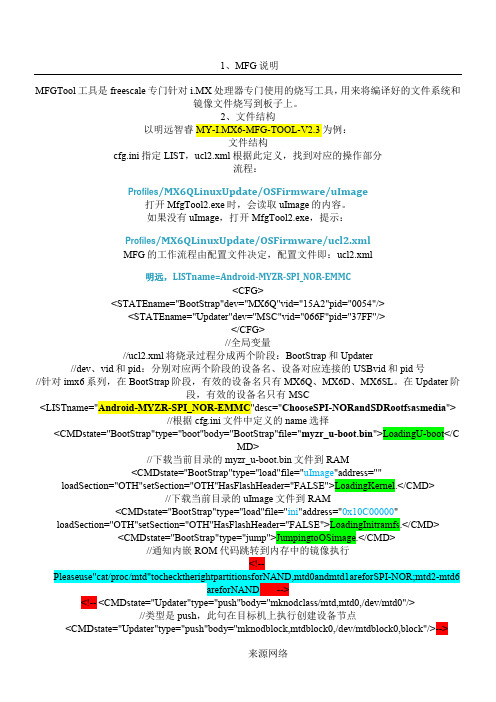
1、MFG说明MFGTool工具是freescale专门针对i.MX处理器专门使用的烧写工具,用来将编译好的文件系统和镜像文件烧写到板子上。
2、文件结构以明远智睿MY-I.MX6-MFG-TOOL-V2.3为例:文件结构cfg.ini指定LIST,ucl2.xml根据此定义,找到对应的操作部分流程://针对阶"> loadSection="OTH"setSection="OTH"HasFlashHeader="FALSE">LoadingInitramfs.</CMD> <CMDstate="BootStrap"type="jump">JumpingtoOSimage.</CMD>//通知内嵌ROM代码跳转到内存中的镜像执行<!--Pleaseuse"cat/proc/mtd"tochecktherightpartitionsforNAND,mtd0andmtd1areforSPI-NOR;mtd2-mtd6areforNAND --><!-- <CMDstate="Updater"type="push"body="mknodclass/mtd,mtd0,/dev/mtd0"/>//类型是push,此句在目标机上执行创建设备节点<CMDstate="Updater"type="push"body="mknodblock,mtdblock0,/dev/mtdblock0,block"/>-->//类型是push,此句在目标机上执行,创建设备节点<CMDstate="Updater"type="push"body="$flash_erase/dev/mtd000">ErasingBootpartition</CMD>//擦除信息<CMDstate="Updater"type="push"body="send"file="files/android/u-boot.bin">SendingU-Boot</CMD>//将files/android/u-boot.bin文件发送到目标机<CMDstate="Updater"type="push"body="$ddif=$FILEof=/dev/mtd0bs=512">writeU-BoottoSPI-NOR</CMD>//烧写将$FILE下载到/dev/mtd0位置,bs=512,指定读/写的blocks大小为512bytes <CMDstate="Updater"type="push"body="send"file="">Sendingpartitionshell</CMD> <CMDstate="Updater"type="push"body="$tarxf$FILE">Partitioning...</CMD>em.img">Sendingandwrittingsystem.img</CMD>//利用pipe传输大数据<CMDstate="Updater"type="push"body="frf">flushthememory.</CMD>//执行flush刷新操作,等到数据传输完毕<!--Writeuserdata.imgisoptional,forsomecustomerthisisneeded,butit'soptional.--><!--Also,userdata.imgwillhaveandroidunittest,youcanusethistodosomeautotest.--><!--<CMDstate="Updater"type="push"onError="ignore"body="pipeddof=/dev/mmcblk0p7"file="file/an droid/userdate.img">Sendinguserdata.img(optional)</CMD><CMDstate="Updater"type="push"body="frf">flushthememory.</CMD>-->//注释掉overy.img">Sendingandwrittingrecovery.img</CMD><CMDstate="Updater"type="push"body="frf">Finishingrootfswrite</CMD> <CMDstate="Updater"type="push"body="$echoUpdateComplete!">Done</CMD>//显示执行完毕信息</LIST>官方,LISTname=Android-SabreSD-eMMC<LISTname="Android-SabreSD-eMMC"desc="ChooseeMMCandroidasmedia"><!--AndroidProfile:--><CMDstate="BootStrap"type="boot"body="BootStrap"file="u-boot.bin">LoadingU-boot</CMD>//将blocks <CMDstate="Updater"type="push"body="$tarxf$FILE">Extractingdatapartitionshell</CMD> <CMDstate="Updater"type="push"body="$shmk-encryptable-data-android.sh/dev/mmcblk0/dev/mmcblk0p4">Makingdataencryptable</CMD><CMDstate="Updater"type="push"body="$mkfs.ext4/dev/mmcblk0p5">Formattingsystempartition</CMD><CMDstate="Updater"type="push"body="$mkfs.ext4/dev/mmcblk0p6">Formattingcachepartition</CMD><CMDstate="Updater"type="push"body="frf">flushthememory.</CMD> <CMDstate="Updater"type="push"body="$mkfs.ext4/dev/mmcblk0p7">Formattingdevicepartition</CMD>em.img">Sendingandwrittingsystem.img</CMD><CMDstate="Updater"type="push"body="frf">flushthememory.</CMD> <!--Writeuserdata.imgisoptional,forsomecustomerthisisneeded,butit'soptional.--><!--Also,userdata.imgwillhaveandroidunittest,youcanusethistodosomeautotest.--><!--<CMDstate="Updater"type="push"onError="ignore"body="pipeddof=/dev/mmcblk0p7"file="file/an droid/userdate.img">Sendinguserdata.img(optional)</CMD><CMDstate="Updater"type="push"body="frf">flushthememory.</CMD>--><CMDstate="Updater"type="push"body="pipeddof=/dev/mmcblk0p2bs=512"file="files/android/rec overy.img">Sendingandwrittingrecovery.img</CMD>-f flashandroidimage.EOF}#checktheifroot?userid=`id-u`if[$userid-ne"0"];thenecho"you'renotroot?"exitfi#parsecommandlinemoreoptions=1node="na"cal_only=0flash_images=0not_partition=0not_format_fs=0while["$moreoptions"=1-a$#-gt0];docase$1in-h)help;exit;;-s)cal_only=1;;-f)flash_images=1;;RECOVERY:${RECOVERY_ROM_SIZE}MB SYSTEM:${SYSTEM_ROM_SIZE}MB CACHE:${CACHE_SIZE}MBDATA:${data_size}MBMISC:${MISC_SIZE}MBEOFexitfi#destroythepartitiontableddif=/dev/zeroof=${node}bs=1024count=1sfdisk--force-uM${node}<<EOF,${boot_rom_sizeb},83,${RECOVERY_ROM_SIZE},83,${extend_size},5,${data_size},83,${SYSTEM_ROM_SIZE},83,${CACHE_SIZE},83,${VENDER_SIZE},83,${MISC_SIZE},83EOF#adjustthepartitionreserveforbootloader.MfgtoolusesglobalconfigurationtorecognizewhichdevicetheuserwantstoflashamongdifferentUSBdevicesconnectedtothePC.选择设备与PC相连的USBLet’sexplainitbyanexample.下面为例,说明<CFG><STATEname="BootStrap"dev="MX6Q"vid="15A2"pid="0054"/><STATEname="Updater"dev="MSC"vid="066F"pid="37FF"/></CFG>Globalconfigurationiscontainedbetweenparameter<CFG>and</CFG>.定义的全局配置参数<STATEname="BootStrap"dev="MX6Q"vid="15A2"pid="0054"/>indicatesthefirstphaseoftheburningpro cess,thephasenameis“BootStrap”,andadevicenamed“MX6Q”shouldbeconnectedwiththeUSBpid“0054”an dvid“15A2”.Fori.MX6serial,inthephase“BootStrap”,thevalidstringsfordevare:“MX6Q”,“MX6D”,“MX6S L”;inthephase“Updater”,thevalidstringfordevis:“MSC”.烧录过程的第一步BootStrap<STATEname="Updater"dev="MSC"vid="066F"pid="37FF"/>indicatesthesecondphaseoftheburningproc ess,thephasenameis“Updater”,andadevicenamed“MSC”shouldbeconnectedwiththeUSBpid“37FF”andvid“066F”.theonlythinghosthastodoistosendthecommandtothetargeteddevice.主机只是将命令发给目标机ThecommandsactuallyexecutedbyOSimagearedownloadedin Commandlists.Asaresult,eachOShasitsowncomx6qpll8:50MHzBoard:i.MX6Q-SABRESD:unknown-boardBoard:0x63012[POR]BootDevice:SPINORI2C:readyDRAM:1GBMMC:FSL_USDHC:0,FSL_USDHC:1,FSL_USDHC:2UsingdefaultenvironmentIn:serialOut:serialErr:serialNet:gotMACaddressfromIIM:00:00:00:00:00:00FEC0[PRIME]Hitanykeytostopautoboot:0##BootingkernelfromLegacyImageat...ImageType:ARMLinuxKernelImage(uncompressed)DataSize:3182360Bytes=3MBVerifyingChecksum...OK##LoadinginitRamdiskfromLegacyImageat10c00000...ImageName:ubootinitramfsrootfsImageType:ARMLinuxRAMDiskImage(gzipcompressed)DataSize:4537478Bytes=4.3MBmodules:0x7f000000-0x7fe00000(14MB).text:0x8003a000-0x805b676c(5618kB).bss:0x806062a4-0x806316f0(174kB)SLUB:Genslabs=13,HWalign=32,Order=0-3,MinObjects=0,CPUs=4,Nodes=1 PreemptiblehierarchicalRCUimplementation.NR_IRQS:624MXCGPIOhardwaresched_clock:32bitsat3000kHz,resolution333ns,wrapsevery1431655msarm_max_freq=1GHzMXC_EarlyserialconsoleatMMIO0x2020000(options'115200')bootconsole[ttymxc0]enabledConsole:colourdummydevice80x30Calibratingdelayloop...1581.05BogoMIPS(lpj=7905280)pid_max:default:32768minimum:301Mount-cachehashtableentries:512CPU:Testingwritebuffercoherency:ok hwperfevents:enabledwithARMv7Cortex-A9PMUdriver,7countersavailableCPU1:BootedsecondaryprocessorCPU2:BootedsecondaryprocessorCPU3:BootedsecondaryprocessorBroughtup4CPUs11usbcore:registerednewdevicedriverusbimx-ipuv3imx-ipuv3.0:IPUDMFCNORMALmode:1(0~1),5B(4,5),5F(6,7) imx-ipuv3imx-ipuv3.1:IPUDMFCNORMALmode:1(0~1),5B(4,5),5F(6,7)Bluetooth:Corever2.16NET:Registeredprotocolfamily31Bluetooth:HCIdeviceandconnectionmanagerinitializedBluetooth:HCIsocketlayerinitializedBluetooth:L2CAPsocketlayerinitializedBluetooth:SCOsocketlayerinitializedi2c-core:driver[max17135]usinglegacysuspendmethodi2c-core:driver[max17135]usinglegacyresumemethodSwitchingtoclocksourcemxc_timer1Clockevents:couldnotswitchtoone-shotmode:Clockevents:couldnotswitchtoone-shotmode:Clockevents:couldnotswitchtoone-shotmode:dummy_timerisnotfunctional.Clockevents:couldnotswitchtoone-shotmode:CouldnotswitchtohighresolutionmodeonCPU2dummy_timerisnotfunctional.dummy_timerisnotfunctional.CouldnotswitchtohighresolutionmodeonCPU1CouldnotswitchtohighresolutionmodeonCPU0JFFS2version2.2.(NAND)漏2001-2006RedHat,Inc.msgmnihasbeensetto2017cryptodev:driverloaded.ioschedulernoopregisteredioschedulerdeadlineregisteredioschedulercfqregistered(default)mxc_sdc_fbmxc_sdc_fb.0:registermxcdisplaydriverldb_regulator_get:get()withnoidentifierimx-ipuv3imx-ipuv3.0:IPUDMFCDPHIGHRESOLUTION:1(0,1),5B(2~5),5F(6,7) Console:switchingtocolourframebufferdevice128x37mxc_sdc_fbmxc_sdc_fb.1:registermxcdisplaydriverhdmimxc_hdmimxc_hdmi:DetectedHDMIcontroller0x13:0xa:0xa0:0xc1fbcvt:1920x1080@60:CVTName-2.073M9------------[cuthere]------------WARNING:atmm/page_alloc.c:2121__alloc_pages_nodemask+0x150/0x64c()Moduleslinkedin:[<800469f0>](unwind_backtrace+0x0/0xf8)from[<800731b8>](warn_slowpath_common+0x4c/0x64) [<800731b8>](warn_slowpath_common+0x4c/0x64)from[<800731ec>](warn_slowpath_null+0x1c/0x24)[<800731ec>](warn_slowpath_null+0x1c/0x24)from[<800bf5b4>](__alloc_pages_nodemask+0x150/0x64c)imx-uart.4:ttymxc4atMMIO0x21f4000(irq=62)isaIMXloop:moduleloadedm25p80spi0.0:sst25vf016b(2048Kbytes)Creating2MTDpartitionson"m25p80":0x000000000000-0x000000180000:"bootloader"0x000000180000-0x000000200000:"kernel"GPMINANDdriverregistered.(IMX)vcan:VirtualCANinterfacedriverFECEthernetDriverfec_enet_mii_bus:probedInitializingUSBMassStoragedriver...22usbcore:registerednewinterfacedriverusb-storageUSBMassStoragesupportregistered.ARCUSBOTGDeviceControllerdriver(1August2005)addwakeupsourceirq75g_file_storagegadget:controller'fsl-usb2-udc'notrecognized check_parameters:UTPsettingsareinplacenow,overridingdefaults g_file_storagegadget:Noserial-numberstringprovided!g_file_storagegadget:File-backedStorageGadget,version:1September2010 g_file_storagegadget:NumberofLUNs=1fsl-usb2-udc:bindtodriverg_file_storagemxc_asrcregistered22usbcore:registerednewinterfacedriverusbhidusbhid:USBHIDcoredriverCirrusLogicCS42888ALSASoCCodecDriveri2c-core:driver[cs42888]usinglegacysuspendmethodi2c-core:driver[cs42888]usinglegacyresumemethodimx_3stackasocdriverALSAdevicelist:Nosoundcardsfound.TCPcubicregisteredNET:Registeredprotocolfamily17NET:Registeredprotocolfamily29Bluetooth:RFCOMMTTYlayerinitializedBluetooth:RFCOMMsocketlayerinitializedBluetooth:RFCOMMver1.11Bluetooth:BNEP(EthernetEmulation)ver1.3Bluetooth:BNEPfilters:protocolmulticastBluetooth:HIDP(HumanInterfaceEmulation)ver1.2VFPsupportv0.3:implementor41architecture3part30variant9rev4BusfreqdrivermoduleloadedBusfreqdriverEnabledcpu_idis0//<CMDstate="Updater"type="push"body="$flash_erase/dev/mtd000">ErasingBootpartition</CMD>UTP:receivedcommand'$flash_erase/dev/mtd000'UTP:executing"flash_erase/dev/mtd000"Erasing4Kibyte@17f000--100%complete//4k4*1024=4096UTP:sendingSuccesstokernelforcommand$flash_erase/dev/mtd000.utp_poll:passreturned.//<CMDstate="Updater"type="push"body="send"file="files/android/u-boot.bin">SendingU-Boot</CMD>UTP:receivedcommand'send'UTP:sendingSuccesstokernelforcommandsend.//<CMDstate="Updater"type="push"body="$ddif=$FILEof=/dev/mtd0bs=512">writeU-BoottoSPI-NOR</CMD>UTP:receivedcommand'$ddif=$FILEof=/dev/mtd0bs=512'UTP:executing"ddif=$FILEof=/dev/mtd0bs=512"442+1recordsin442+1recordsout226788bytes(221.5KB)copied,7.148058seconds,31.0KB/sUTP:sendingSuccesstokernelforcommand$ddif=$FILEof=/dev/mtd0bs=512.Newsituation:Units=mebibytesof1048576bytes,blocksof1024bytes,countingfrom0DeviceBootStartEndMiB#blocksIdSystem/dev/mmcblk0p10+1516-16383+83Linux/dev/mmcblk0p216238819283Linux/dev/mmcblk0p3241103108011059205Extended/dev/mmcblk0p4110438152712277708883Linux/dev/mmcblk0p524+535512-524287+83Linux/dev/mmcblk0p6536+1047512-524287+83Linux/dev/mmcblk0p71048+10558-8191+83Linux/dev/mmcblk0p81056+10638-8191+83LinuxWarning:partition4extendspastendofdiskSuccessfullywrotethenewpartitiontableRe-readingthepartitiontable...mmcblk0:p1p2p3<p5p6p7p8>p4mmcblk0:p4size5554176extendsbeyondEOD,truncatedIfyoucreatedorchangedaDOSpartition,/dev/foo7,say,thenusedd(1)tozerothefirst512bytes:ddif=/dev/zeroof=/dev/foo7bs=512count=1(Seefdisk(8).)Checkingthatno-oneisusingthisdiskrightnow...mmcblk0:p1p2p3<p5p6p7p8>p4Warning:partition4extendspastendofdiskSuccessfullywrotethenewpartitiontableRe-readingthepartitiontable...mmcblk0:p1p2p3<p5p6p7p8>p4mmcblk0:p4size5554176extendsbeyondEOD,truncatedIfyoucreatedorchangedaDOSpartition,/dev/foo7,say,thenusedd(1)tozerothefirst512bytes:ddif=/dev/zeroof=/dev/foo7bs=512count=1(Seefdisk(8).)UTP:sendingSuccesstokernelforcommand$shmksdcard-android.sh/dev/mmcblk0.utp_poll:passreturned.//<CMDstate="Updater"type="push"body="$ls-l/dev/mmc*">Formattingsdpartition</CMD>UTP:receivedcommand'$ls-l/dev/mmc*'UTP:executing"ls-l/dev/mmc*"brw-r-----1rootdisk179,0Jan100:00/dev/mmcblk0brw-r-----1rootdisk179,8Jan100:00/dev/mmcblk0boot0brw-r-----1rootdisk179,16Jan100:00/dev/mmcblk0boot1brw-r-----1rootdisk179,1Jan100:00/dev/mmcblk0p1brw-r-----1rootdisk179,2Jan100:00/dev/mmcblk0p2brw-r-----1rootdisk179,3Jan100:00/dev/mmcblk0p3brw-r-----1rootdisk179,4Jan100:00/dev/mmcblk0p4brw-r-----1rootdisk179,5Jan100:00/dev/mmcblk0p5UTP:executing"mkfs.ext4-Ldata/dev/mmcblk0p4"mke2fs1.41.4(27-Jan-2009)Filesystemlabel=dataOStype:LinuxBlocksize=4096(log=2)Fragmentsize=4096(log=2)171024inodes,684032blocks34201blocks(5.00%)reservedforthesuperuserFirstdatablock=021blockgroups32768blockspergroup,32768fragmentspergroup8144inodespergroupSuperblockbackupsstoredonblocks:32768,98304,163840,229376,294912Writinginodetables:doneCreatingjournal(16384blocks):doneWritingsuperblocksandfilesystemaccountinginformation:doneThisfilesystemwillbeautomaticallycheckedevery33mountsor180days,etune2fs-cor-itooverride.UTP:sendingSuccesstokernelforcommand$mkfs.ext4-Ldata/dev/mmcblk0p4.UTP:receivedcommand'$mkfs.ext4-Lcache-O^extent/dev/mmcblk0p6' UTP:executing"mkfs.ext4-Lcache-O^extent/dev/mmcblk0p6"mke2fs1.41.4(27-Jan-2009)Filesystemlabel=cacheOStype:LinuxBlocksize=1024(log=0)Fragmentsize=1024(log=0)131072inodes,524284blocks26214blocks(5.00%)reservedforthesuperuserFirstdatablock=164blockgroups8192blockspergroup,8192fragmentspergroup2048inodespergroupSuperblockbackupsstoredonblocks:8193,24577,40961,57345,73729,204801,221185,401409Writinginodetables:doneCreatingjournal(8192blocks):doneWritingsuperblocksandfilesystemaccountinginformation:doneThisfilesystemwillbeautomaticallycheckedevery35mountsor180days,etune2fs-cor-itooverride.//<CMDstate="Updater"type="push"body="frf">flushthememory.</CMD>UTP:receivedcommand'frf'UTP:sendingSuccesstokernelforcommandfrf.utp_poll:passreturned.//<CMDstate="Updater"type="push"body="$mkfs.ext4/dev/mmcblk0p8">Formattingmiscpartition</CMD>UTP:receivedcommand'$mkfs.ext4/dev/mmcblk0p8'UTP:executing"mkfs.ext4/dev/mmcblk0p8"mke2fs1.41.4(27-Jan-2009)Filesystemlabel=OStype:LinuxBlocksize=1024(log=0)Fragmentsize=1024(log=0)2048inodes,8188blocks409blocks(5.00%)reservedforthesuperuserFirstdatablock=1Maximumfilesystemblocks=83886081blockgroup8192blockspergroup,8192fragmentspergroup2048inodespergroupWritinginodetables:done10592+0recordsin10592+0recordsout5423104bytes(5.2MB)copied,1.458177seconds,3.5MB/sUTP:closingthefileUTP:sendingSuccesstokernelforcommandfrf.utp_poll:passreturned.//<CMDstate="Updater"type="push"body="$echoUpdateComplete!">Done</CMD> UTP:receivedcommand'$echoUpdateComplete!'UTP:executing"echoUpdateComplete!"UpdateComplete!UTP:sendingSuccesstokernelforcommand$echoUpdateComplete!.utp_poll:passreturned.。
常用英文说明
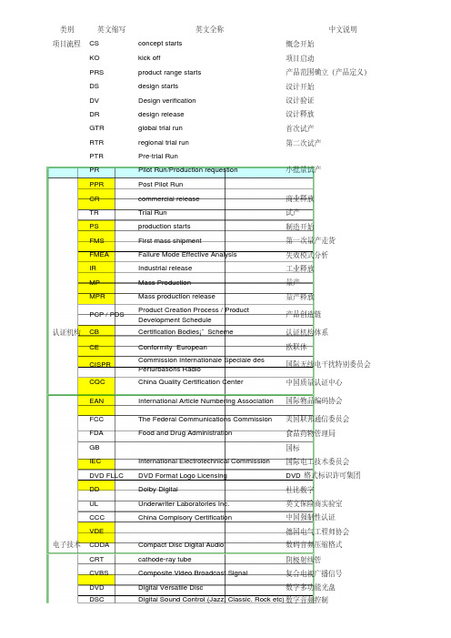
类别英文缩写英文全称中文说明项目流程CS concept starts概念开始KO kick off项目启动PRS product range starts产品范围确立(产品定义)DS design starts设计开始DV Design verification设计验证DR design release设计释放GTR global trial run首次试产RTR regional trial run第二次试产PTR Pre-trial RunPR Pilot Run/Production requestion小批量试产PPR Post Pilot RunCR commercial release商业释放TR Trial Run试产PS production starts制造开始FMS First mass shipment第一次量产走货FMEA Failure Mode Effective Analysis失效模式分析IR Industrial release工业释放MP Mass Production量产MPR Mass production release量产释放PCP / PDS Product Creation Process / ProductDevelopment Schedule产品创造链认证机构CB Certification Bodies¡¯ Scheme认证机构体系CE Conformity European欧联体CISPR Commission Internationale Speciale desPerturbations Radio国际无线电干扰特别委员会CQC China Quality Certification Center中国质量认证中心EAN International Article Numbering Association国际物品编码协会FCC The Federal Communications Commission美国联邦通信委员会FDA Food and Drug Administration食品药物管理局GB国标IEC International Electrotechnical Commission国际电工技术委员会DVD FLLC DVD Format Logo Licensing DVD 格式标识许可集团DD Dolby Digital杜比数字UL Underwriter Laboratories Inc.英文保险商实验室CCC China Complsory Certification中国强制性认证VDE德国电气工程师协会电子技术CDDA Compact Disc Digital Audio数码音频压缩格式CRT cathode-ray tube阴极射线管CVBS Composite Video Broadcast Signal复合电视广播信号DVD Digital Versatile Disc数字多功能光盘DSC Digital Sound Control (Jazz, Classic, Rock etc)数字音频控制DPL Dolby Prologic杜比定向逻辑DTS Digital theatre system数字影院系统EDV electrical design verification电子设计版本EDR electrical design report电子设计报告ETA Estimated Time of Arrival抵达评估时间ETD Estimated Time of Departure预订出发时间EVD Enhanced Versatile Disc新一代多媒体高清晰视盘系统FTD Field Terminated Diode场终止二极管FTS Favorite Track Selection最佳轨道选择HDMI High Definition Multimedia Interface数字高清晰多媒体接口HSIHue-Saturation-Intensity色调-饱和度-强度HSIhardware software interface软硬件界面DAC Digital Audio Compress数字音频压缩JPEG Joint Photogragh Coding Experts Group联合图象专家组, 一种压缩标准。
产品说明书翻译

减译
• As soon as you start charging the empty shaver, the green pilot light will go on.
• 电剃刀充电时,绿色指示灯马上亮起。
rolls out and the door opens • ③ Place articles inside and
close the door
• To remove contents • ① Place barcode against the
scanner and the door opens • ② Remove the contents and
after opening.
• 切勿带包装置于微波炉中加热。 • Do not microwave with the packaging.
• 操作前请仔细阅读使用说明。 • Read and understand this manual before operating it.
存包处使用说明
•存 • ① 请按“存〞键。 • ② 取密码纸,自动开箱。 • ③ 存入物品,关好箱门。 •取 • ① 将密码纸靠近读码口自动开箱。 • ② 取物后,请关好箱门。
close the door
• 3〕被动语态 • This moisturiser is specially developed for
normal and combination skin. • 本滋润霜特为中性和混合性皮肤设计。
• 应当注意食品的保质期。 • 译文:Attention must be paid to the shelf
好马滕制造公司 L.P. 用户信息手册 - 包装气电热水器说明书

Goodman Manufacturing Company, L.P .5151 San Felipe, Suite 500, Houston, TX 77056© 2004, 2007, 2009 - 2011, 2014 - 2015 Goodman Manufacturing Company, L.P.USER’S INFORMATION MANUALP ACKAGE G AS -E LECTRICInstaller -Affix this manual, Installation Guide, and Warranty adjacent to the appliance.Owner -Read and keep all product literature in a safe place for future reference.RECOGNIZE THIS SYMBOL AS A SAFETY PRECAUTION.HI-116E 7/152S IGNAL W ORDSDear Homeowner, please recognize the following safety infor-mation. This information will alert you to the potential for per-sonal injury.- Indicate hazards or unsafe practices which result in severe personal injury or death.Before using this manual, check the serial plate for propermodel identification.The installation and servicing of this equipment must be performed by qualified, experienced technicians only.G ENERAL I NFORMATIONU NIT L OCATIONThis unit is approved only for an outdoor installation. See the installation instructions for the required clearances to the unit. It is important that safety measures are taken in the surrounding area of the unit.Gutters or deflectors must be installed on the roof to prevent water from shedding on the unit.1.An area must be available to reach the unit in a clear and unobstructed path.2.The unit area and the vicinity of any other gas appliances must be kept clear and free of combustible materials, gaso-line, and other flammable vapors and liquids. Also, do not store or use flammable items such as paint, varnish, or lac-quer in the area.3.The combustion air supply must not be contaminated by prod-ucts containing chlorine or fluorine, as they could corrode the heat exchanger. If you need further information on this sub-ject, contact your installing dealer or another qualified ser-vicer.4.Familiarize yourself with the controls that turn off the gas and electrical power to the unit.5.Establish a regular service and maintenance schedule to ensure efficient and safe operation of the unit.6.The unit must be placed where no runoff water from higher ground can collect in the unit.U NIT I NSTALLATIONExamine the unit installation to determine the following:1.The flue hood connector is in place and is physically sound without holes or excessive corrosion.2.The mounting pad support of the unit is sound.3.There are no obvious signs of deterioration of the unit.4.The burner flames are stable, soft and blue, (dust may cause orange tips but must not be yellow). The flames should ex-tend directly outward from the burner without curling, floating,or lifting off. To examine, turn on the electrical power and gas.Set the room temperature to the maximum setting.BurnerNOTE: If a strong wind is blowing, it may not be possible to perform the flame inspection.A IR REQUIREMENTSSince the gas/electric unit is installed completely in the outdoors, the depletion of combustion air is highly improbable. To ensure an adequate supply of combustion air, do not allow the combus-tion air inlet or the flue hood outlet to become blocked by leaves, snow, rubbish, or insect (wasps) nests. Never block the con-densing unit section in the winter with covers. Blocking of this section would prevent an adequate amount of combustion air from reaching the furnace section.Great care has been taken in the design and manufacture of your unit to provide for your comfort and safety. Be aware of the possibility that some problems with your unit or other gas-fired appliances could cause flue gases to be present in your building. These flue gases could include carbon monoxide.3T HERMOSTA TThis unit will not operate properly without a good quality, correctly installed thermostat. It is very important that the thermostat be located where it can best “sense” the average room temperature. Be sure the thermostat is not exposed to hot or cold drafts or to hot or cold spots on the wall, such as those received from outside walls, walls with pipes inside, or from openings into the attic. No matter the type or style, thermostat operation is basically the same. The most widely used types will control both heating and cooling functions and will have a Fan Switch with Auto and ON settings. On Auto, the Circulating Air Blower will cycle on/off, but if switched to ON it will run constantly.For Dual Fuel units (GPD/APD), a Dual Fuel thermostat with an outdoor temperature sensor is recommended for optimal opera-tion.IMPORTANT NOTE: To avoid the possibility of damage to the unit heat exchanger, do not set the thermostat fan switch to ON (constant fan operation) during the heating season without first consulting the installer of the unit or another qualified servicer. There are thermostats that automatically switch from Heating to Cooling, or with night setbacks. The night setback, or multiple setback type, will lower the temperature at night or during the day when the building is unoccupied.Propane (LP) Gas Installations OnlyFor units operating on propane gas, please review the following warnings before use.O PERATING INSTRUCTIONSH EATING S TART U PTo put your unit into operation, follow the steps listed below.1.Close the external manual gas shutoff valve.2.Turn off the electrical power to the unit.3.Set the room thermostat to the lowest possible setting.4.Remove the heat exchanger door on the side of the unit byremoving screws.5.This unit is equipped with an ignition device which automati-cally lights the burner. Do not try to light the burner by hand.6.Move the gas control switch to the OFF position. Do not useexcessive force.7.Wait five minutes to clear out any gas. Then smell for gas,including near the floor as some types of gas are heavier than air.8.If you smell gas following the five minute waiting period instep 7, immediately follow the instructions on the cover of this manual. If you do not smell gas after five minutes, move or rotate the gas control switch to the ON position. The switch should turn easily. Do not use excessive force.9.Reinstall the burner compartment door.10.Open the external manual gas shutoff valve.11.Turn on the electrical power to the unit.12.Adjust the thermostat to a setting above room temperature.13.After the burners are lit, set the thermostat to desired tem-perature.H EATING S HUT D OWNTo shut down operation, follow the steps listed below.1.Set the thermostat to the lowest setting.2.Turn OFF electrical power to the unit.3.Remove the heat exchanger door on the side of the unit byremoving screws.4.Move the gas control switch to the OFF position. Do not useexcessive force.5.Close the external manual gas shutoff valve.6.Reinstall the heat exchanger door.7.If cooling and/or air circulation is desired, turn ON the electri-cal power.C OOLING O PERATIONCooling operation may be obtained as follows:1.Place the room thermostat selector switch in the COOL po-sition (or AUTO, if available, and if automatic changeover from cooling to heating is desired).2.Set the room thermostat to the desired temperature.3.If cooling system does not energize, wait five minutes. Thesystem startup may be delayed by the short-cycle protector feature of the ignition control board. Check the manual reset devices on the rollout limit, as described in this manual.OUTLET Gas ValveOn/OffSelectorSwitchWhite-Rodgers Model 36F224SelectorSwitchINLET OUTLETWhite-Rodgers Model 36G22High RegulatorWhite-Rodgers Model 36G54Honeywell Model VR8215 (Single-Stage)S AFETY C IRCUITSA number of safety circuits are employed to ensure safe and proper unit operation. These circuits serve to control any poten-tial safety hazards and, as inputs in the monitoring and diagnosis of abnormal operation.S ECONDARY L IMITThe secondary limit control is located on the blower housing and monitors blower compartment temperatures. It is a normally closed (electrically), automatic reset, temperature activated sensor. This limit guards against overheating as a result of insufficient conditioned air passing over the heat exchanger. It deenergizes the gas valve if the blower fails.NOTE: If the power to the unit is interrupted during the heating cycle, it may cause the secondary limit to trip. Once the blower compartment temperature drops below the limit reset temperature, the limit will automatically reset.Secondary Limit ControlR OLLOUT L IMITThe rollout limit is a normally-closed (electrically), manual-reset, temperature-activated sensor. It is mounted on the burnerbracket and monitors the burner flame. If there is an improper draw of burner flames into the heat exchanger, the rollout limit will detect it and shut off gas flowing to the burners. Contact a qualified servicer to check the unit before resetting this device.Rollout Protection on Burner Bracket56C OMPRESSOR P ROTECTIOND EVICESThis gas/electric package unit includes components which are designed to protect the compressor against abnormal operat-ing conditions.NOTE: The operation of the indoor blower will not be affected by any compressor protection devices.If, during a call for cooling, the indoor fan runs and circulates room temperature air while the compressor and outdoor fan do not operate:1.Wait five minutes, as a protection device may be holding the compressor off.2.Check the room thermostat to see if it is correctly set.3.If the room thermostat is correctly set, call a qualified servicer to determine if one of the compressor protection devices has opened.S HORT -C YCLE P ROTECTORA short-cycle protector is built into the ignition control. Each time the compressor is off for less than 3 minutes, the short-cycle protector will delay compressor startup for up to 3 minutes. This protects the compressor from improper operation.On Dual Fuel units (GPD/APD), the short-cycle protector will delay the compressor 5 minutes.NOTE: These units are not designed to provide mechanical cooling at outdoor temperatures below 50°F. If low ambient cooling is needed, consult a qualified servicer.I GNITERThe unit has an electronic ignition device which lights the burners automatically. Never try to light the burners by hand. It also has an induced draft blower to exhaust combustion prod-ucts.I NDOOR A IR C IRCULATOR B LOWERKeep the blower access door panel in place except for inspec-tion and maintenance.R OUTINE M AINTENANCEIf you perform maintenance on the unit yourself, remember that certain mechanical and electrical knowledge, skills and tools are required to perform unit maintenance. Personal injury or death may result If you are not properly trained. You should call your installing dealer or place of purchase if you are uncertainabout your ability to perform maintenance.A NNUAL I NSPECTIONYour package unit should be inspected by a qualified installer,or service agency at least twice every year. This check should be performed before the heating and cooling seasons begin. This will ensure that adequate combustion air is being drawn and the vent system is working properly. Particular attention should be paid to the following items. Repair as necessary.•Check physical support of the unit. Ensure it is sound with-out any sagging, cracks, or gaps, around the base.•Check for obvious signs of deterioration of the unit.•Flue Hood and Combustion Air Inlet. Check for blockage (wasp nest, etc.) and corrosion.Flue Hood•Return Air Connection. Check for physical soundness and ensure that the connection is firmly sealed to the package unit casing.•Heat exchanger. Check for corrosion and/or obstructions within the heat exchanger passageways.•Burners. Check for proper ignition, burner flame, and flame sense.•Wiring. Check electrical connections for tightness and/or corrosion. Check wires for damage.•Filters. Check that filters are clean and in the proper place-ment in the unit or duct system.•Louvers. Inspect air inlet louvers inside the heat exchanger compartments. Ensure the area is clean and free of dirt and debris.R EPLACING OR C LEANING F ILTERIMPORTANT NOTE: Never operate unit without a filter installed as dust and lint will build up on internal parts resulting in loss of efficiency, equipment damage and possible fire.A return air filter is not supplied with this unit; however, there must be a means of filtering the return air. The filter(s) may be located in the return air duct(s). Consult with your installing dealer for the actual location of the return air filter(s) in your unit.A dirty filter is the most common cause of inadequate heating or cooling performance. Filter inspection should be made at least every two months; more often if necessary because of local conditions and usage.Dirty throwaway filters should be discarded and replaced with a new, clean filter. Dirty permanent filters should be washed with water, thoroughly dried and sprayed with a filter adhesive before being reinstalled. (Filter adhesives may be found at many hard-ware stores.) Permanent filters should last several years. How-ever, should one become worn or uncleanable, it should be replaced.When installing a new filter or reinstalling an old one, always make certain the air flow arrows on the filter point in the proper direction.C LEAN O UTSIDE C OIL (Q UALIFIED S ERVICER O NLY)The coil with the outside air flowing over it should be inspected annually and cleaned as frequently as necessary to keep the finned areas free of leaves, grass, seeds, and debris.C ONDENSER, E VAPORATOR, AND I NDUCED D RAFT M OTORS Bearings on the air circulating blower motor, condenser motor and the combustion fan motor are permanently lubricated. No additional oiling is required.C OMPRESSORThe compressor motor is hermetically sealed and does not require additional oiling.S AFETY L ABELSNOTE: If safety labels are missing or illegible, contact the installing dealer.To obtain the proper safety labels, the Model and Serial Number of the unit must be supplied. These numbers are recorded on the nameplate of the unit. For convenience, record this information here:MODEL NUMBER:_____________________________________SERIAL NUMBER:_____________________________________78S AFETY L ABELSF OR A DDITIONAL I NFORMATIONMost questions can be answered by your local dealer. If you have other matters that cannot be resolved locally,or you need additional information regarding other heating and cooling products offered by us - please call:CONSUMER INFORMA TION LINE:TOLL FREE1-877-254-4729 (U.S. only)emailusat:******************************fax us at: (731) 856-1821(Not a technical assistance line for dealers.)________________Outside the U.S., call 1-713-861-2500.(Not a technical assistance line for dealers.)Your telephone company will bill you for the call.SAFETY LABELS9SAFETY LABELS10SAFETY LABELS11Goodman Manufacturing Company, L.P. 5151 San Felipe, Suite 500, Houston, TX 77056 12。
- 1、下载文档前请自行甄别文档内容的完整性,平台不提供额外的编辑、内容补充、找答案等附加服务。
- 2、"仅部分预览"的文档,不可在线预览部分如存在完整性等问题,可反馈申请退款(可完整预览的文档不适用该条件!)。
- 3、如文档侵犯您的权益,请联系客服反馈,我们会尽快为您处理(人工客服工作时间:9:00-18:30)。
Manufacturing Tool User Manual Copyright © 2008 Freescale Semiconductor, Inc. All rights reserved.All contents of this document are protected by copyright law and may not be reproduced without the express written consent of Freescale Semiconductor, Inc.Freescale Semiconductor, the Freescale Semiconductor logo, and combinations thereof are trademarks of Freescale Semiconductor, Inc. Other product names used in this publication are for identification purposes only and may be trademarks or registered trademarks of their respective companies. The contents of this document are provided in connection with Freescale Semiconductor, Inc. products. Freescale Semiconductor, Inc. has made best efforts to ensure that the information contained herein is accurate and reliable. However, Freescale Semiconductor, Inc. makes no warranties, express or implied, as to the accuracy or completeness of the contents of this publication and isCopyright © 2010 Freescale Semiconductor, Inc. All rights reserved.The following are trademarks or service marks of Freescale Semiconductor, Inc., and may be used to identify Freescale Semiconductor products or services only: Freescale Semiconductor, the Freescale Semiconductor Logo, C-Major, D-Major and GoChip. Other products, services and company names contained herein may be trademarks or service marks of their respective owners.Manufacturing Tool License AgreementIMPORTANT--READ THESE TERMS CAREFULLY AND MAKE SURE THAT YOU UNDERSTAND THEM BEFORE USING THIS SOFTWARE; DO NOT USE THIS SOFTWARE IF YOU DO NOT AGREE TO THE FOLLOWING TERMS: This Manufacturing Tool License Agreement ("Agreement") is a legal agreement between you (either an individual or a single entity) and Freescale Semiconductor, Inc. (Freescale Semiconductor), for the Manufacturing Tool Software which may include associated software components, software licensed by Freescale Semiconductor from third parties (Licensors), media, printed materials, and "online" or electronic documentation ("Software Product"). By installing, copying, or otherwise using the Software Product, you agree to be bound by the terms of this Agreement. The Software Product is protected by copyright laws and international copyright treaties, as well as other intellectual property laws and treaties.1. GRANT OF LICENSE. Freescale Semiconductor grants you the right to install and use the Software Product on your computers running validly licensed copies of the operating system for which the Software Product was designed [e.g., Windows 2000®, Windows® XP, etc.]. You may also make copies of the Software Product as may be necessary for backup and archival purposes.2. PROHIBITIONS AND RESTRICTIONS. You must not remove or alter any copyright notices on all copies of the Software Product. You may not distribute copies of the Software Product to third parties, other than your manufacturing contractors who have agreed to maintain the Software Product in strict confidence. You may not rent, lease, or lend the Software Product. You may not reverse-compile, disassemble, reverse-engineer, or use any other method to convert the Software Product into a human-readable form, nor may you allow another person to do so. The Software Product may not be duplicated, corrected, modified, or disposed of in any other way in part or in whole. The creation of derivative works based on the content of the Software Product is also prohibited. You may not export or import the Software Product in violation of United States or foreign government export control laws and regulations.3. COPYRIGHT. All title, including but not limited to copyrights, in and to the Software Product and any copies thereof are owned by Freescale Semiconductor or its Licensors. All title and intellectual property rights in and to the content which may be accessed through use of the Software Product is the property of the respective owner and may be protected by applicable copyright or other intellectual property laws and treaties. This Agreement grants you no rights to use such content. All rights not expressly granted are reserved by Freescale Semiconductor.4. NO WARRANTIES AND LIMITATION OF LIABILITY. The Software Product and any related documentation were developed at, and are copyrighted by, Freescale Semiconductor and/or its Licensors. The Software Product is offered "AS IS" and neither Freescale Semiconductor nor its Licensors make any warranty, or grant any indemnity, with respect to its use or performance. THE ENTIRE RISK ARISING OUT OF USE OR PERFORMANCE OF THE SOFTWARE PRODUCT REMAINS WITH YOU. FREESCALE SEMICONDUCTOR AND ITS LICENSORS DO NOT AND CANNOT WARRANT THE PERFORMANCE OR RESULTS YOU MAY OBTAIN BY USING THE SOFTWARE OR DOCUMENTATION. NEITHER FREESCALE SEMICONDUCTOR NOR ITS LICENSORS MAKE ANY WARRANTIES, EXPRESS OR IMPLIED, AS TO NON-INFRINGEMENT OF THIRD PARTY RIGHTS, MERCHANTABILITY, OR FITNESS FOR ANY PARTICULAR PURPOSE. IN NO EVENT WILL FREESCALE SEMICONDUCTOR OR ITS SUPPLIERS BE LIABLE TO YOU FOR ANY CONSEQUENTIAL, INCIDENTAL OR SPECIAL DAMAGES, INCLUDING ANY LOST PROFITS OR SAVINGS, OR LOSS OF DATA, EVEN IF A FREESCALE SEMICONDUCTOR REPRESENTATIVE HAS BEEN ADVISED OF THE POSSIBILITY OF SUCH DAMAGES, OR FOR ANY CLAIM BY ANY THIRD PARTY.5. GENERAL. If any provision of this Agreement is held unenforceable, that provision shall be enforced to the maximum extent permissible so as to give effect the intent of this Agreement, and the remainder of this Agreement shall continue in full force and effect. This Agreement shall be governed by the laws of the United States and the State of Texas, without reference to conflict of laws provisions thereof, and without regard to the United Nations Convention on Contracts for the International Sales of Goods.TABLE OF CONTENTS1.SCOPE (5)2.INTRODUCTION (5)3.SYSTEM REQUIREMENTS (5)4.INSTALLATION AND SETUP (5)4.1.Installing the Manufacturing Tool (5)4.2.Physical Setup (6)5. APPLICATION OVERVIEW (7)4.3.The Player Profile (7)4.4.Player Operations (8)4.5.The Operations Panels (8)B Ports (9)4.7.The Status Information Panel (9)4.8.The Start/Stop Button (9)5.CONFIGURING THE APPLICATION (10)5.1.Profiles (tab) (11)5.1.1.Create player.ini through text editor (12)5.1.2.Profile/Operation Configuration Status (12)5.1.3.Profile (drop-down list) (13)5.1.4.Operations (list) (13)5.1.4.1.Operation (13)5.1.4.2.Folder (13)5.1.4.3.Files (13)5.1.4.4.Options (13)5.1.5.Operations (menu) (13)5.1.5.1.Enable (13)5.1.5.2.Edit (14)5.1.5.3.Move up (14)5.1.5.4.Move down (14)5.1.6.Operation Editor (dialog) (14)5.1.6.1.UTP_UPDATE Operation (14)5.1.6.1.1Select the UCL command list from the file (14)5.1.6.2.MX_Update Operation (14)B Ports (tab) (15)5.3.General (tab) (16)5.3.1.Options (16)5.3.2.AutoPlay (17)6.OPERATION (17)6.1.UTP mode operation (17)6.2.RKL mode operation (17)7.CONFIGURING THE OPERATION (18)8.INITIALIZING THE SYSTEM (18)8.1.Step 1 - Pre-Loading the i.MX device USB Driver (18)8.1.1.HID mode driver (18)8.1.2.i.MX bulk-IO driver (18)8.2.Step 2 - Pre-Loading the Static-ID USB Mass Storage Driver (19)8.3.Step 3 - Reboot the System (19)9.RUNNING THE APPLICATION (20)10.REGISTRY SCRUB (20)10.1.Profile Description (drop-down list) (21)10.2.Clean (button) (21)10.3.Close (button) (21)10.4.Remove Static-ID Entries (checkbox) (22)11.APPENDIX (22)11.1.Troubleshooting (22)11.2.Error Codes (24)1.SCOPEThis document explains how to use Freescale Semiconductor‟s i.MX Manufacturing Tool (MfgTool). It isintended for Freescale Semiconductor customers, or their OEMs, who plan to mass manufacture i.MXbased products.2.INTRODUCTIONThe i.MX Manufacturing Tool is designed to expedite flashing of firmware and copying of files into i.MXbased hardware. Manufacturing enhancements over the end-user application, include:∙Parallelism – up to 16 devices can be updated concurrently. More concurrent updates may require additional computing resources such as processor speed and memory.∙Continuous operation – operations automatically begin with the arrival of a new device, and multiple operations such as Update and Copy can be linked together seamlessly.∙Enumeration –static-id firmware loaded into RAM in recovery-mode prevents Windows® from enumerating every device.∙ AutoPlay - various Windows® …pop-up‟ application and st atus messages, such as Explorer in Windows® XP, and “Unsafe hardware removal” in Windows® 2000, are suppressed.∙Registry – in addition to minimizing Windows® registry entries, an integrated utility is provided to keep the registry in good operating order.The i.MX Manufacturing Tool is designed to flash firmware onto storage devices like NAND, eSD and pre-load the data area with media files in an efficient and convenient manner. The application is NOTdesigned to test the devices or to diagnose manufacturing problems. Devices initialized with thisapplication still need to be functionally verified.In order to maximize manufacturing efficiency, please READ THIS ENTIRE DOCUMENT and follow the procedures as outlined. The setup and configuration for this application is extensive and must be followed in order to provide the speed enhancements and operator ease outlined above.3.SYSTEM REQUIREMENTSMinimum PC Requirements – 2.0 GHz CPU, 1GB RAMWindows® XP w/Service Pack 2 or laterEither separate internal USB 2.0 controllers or external USB 2.0 powered(2.5 A) hubs.4.INSTALLATION AND SETUP4.1.Installing the Manufacturing ToolThere is no installation application for the MfgTool application. Simply create a folder where theapplication will reside and copy it there. The included example profiles may be copied to aProfiles folder under the folder where the MfgTool application is copied.A shortcut may be created to launch the application from a desktop icon, or the start menu.4.2.Physical SetupConnect the devices according to one of the diagrams below. Figure 1 represents the USB hub based physical setup configuration.Figure 1Connect an external USB 2.0 powered(2.5 A) hub to the PC‟s USB connection. The PC should recognize the external USB hub. The USB ports(up to 16) on the external hub(s) will be configured for use by the Manufacturing Tool (see Section 5.1.6.1.1). Please note that the hub needs to be USB 2.0 compliant and also needs to be externally powered with a 2.5 A power supply, and not bus powered.Figure 2 represents the direct connect setup configuration. Each device connects to a single port on an internal PCI USB controller. This configuration is limited to the number of PCI slots available.Figure 25. APPLICATION OVERVIEWThis section introduces the application‟s main window , describes the function of the various elements, and defines terms necessary to describe the overall program operation. The main application window ‟s un-initialized state is shown here in Figure 3, and the main window‟s running state is shown at the end ofthis section in Figure .Figure 3 4.3. The Player Profile MfgTool centers around Player Profiles. A Player Profile (profile) is a directory containing all the information about a particular product, including a configuration file named player.ini which specifies the name of the product, USB IDs, SCSI IDs, etc, device firmware files, and media files, etc. The profile also contains a list of one or more Player Operations(operations) to be performed on devices matching the profile.The Profile control of the Status Information area window displays the currently selected profileMenu ItemsOperationPanelsA-DUSB PortAssignmentStart/Stop ButtonProfileSelectionand Status(see Figure ). Use this control to choose one from a bench of profiles.Creating and editing profiles is explained in Section 5, under the main heading, Configuring the Application.The Start/Stop button in the Status Information Panel will not be enabled unless a valid profile is selected.4.4.Player OperationsEach Player Profile has a list of one or more Player Operations (operations) that are to be performed on the device matching the profile. Currently there are two types of operations supported by MfgTool: UTP_UPDATE and MX_UPDATE. Instructions regarding the creation, editing and enabling of operations begins in Section 5.0under the main heading, Configuring the Application.Enabled operations begin executing after the Start button in the main application window has been pressed. If a profile lists multiple operations, the enabled operations will be run consecutively, one after the other. The status of the operations is displayed in its Operations Panel.Once all of the operations for a particular device are complete, the user simply needs to remove the device from the USB port, and replace it with the next device. The operations will automatically begin on the new device.Operations are executed on a port-by-port basis. The operations on one USB port are independent of the operations on another USB port.4.5.The Operations Panels4.5.1.1.1 The main application window contains multipleconfigurable in the USB port configuration, and may beB, C, and up to P. Each panel is assigned a physicaldialog (see Section 5.1.6.1.1, Select the UCL commandlist from the fileThe ucl.xml file may contain multiple command lists to accommodate differenthardware configurations or media types. Select the command list to be used forthe MfgTool UTP_UPDATE operation.4.5.1.2. MX_Update OperationThe MX_UPDATE operation is configured in the same manner as theUTP_UPDATE operation. Please refer to the above description to configure theMX_UPDATE operation.USB Ports (tab)). The assigned USB hub and port are shown for each panel (see Figure ), and unassigned panels display Unassigned (see Figure 3).Monitoring - Once a USB port is assigned to a panel, USB device activity on the assigned port is monitored in the corresponding Operations Panel. An Operations Panel is in monitoring mode when a port has been assigned to the panel, and the Start button has not been pressed. The Operation field in the panel (see Figure ) will display Monitoring… when in this mode.In monitoring mode, the panel will display the name of the device connected to its assigned port in the Status Box(see Figure ). If a device is not connected to the assigned port, No device connected is displayed. Any drive letters associated with the connected USB device will be displayed in the panel‟s Drive Letter Box.Running– After the Start button has been clicked, the Operations Panels reflect the operating or running state of the application (see Figure ). The Operation field in the panel will display the type of the current operation when in running mode.As in monitoring mode, the Operations Panel‟s display is directly tied to its assigned USB Port.Any drive letters associated with the connected USB device will be displayed in th e panel‟s Drive Letter Box. The Status Box shows status information about the current operation and the profile‟s list of operations as a whole. Operations Complete is displayed when all of the operations in the profile‟s list have been completed for a device.The Progress Bar indicates progress through the list of operations (see 4). The Progress Bar grows to the right and is BLUE while processing operations. When all operations for a device have been completed, the Progress Bar is completely filled and turns GREEN. A RED Progress Bar indicates an operation failure.Device Completion– A device is complete when all operations have finished successfully. Device completion is shown in the Operations Panel with Operations Complete in the status box, and a completely filled GREEN progress bar.Error Condition– An error condition exists when the Operations Panel displays a RED progress bar. The status box will contain an error message describing the problem, or an error code found in Appendix 9.B Ports4.6.1.1.1 A physical USB port is assigned to an Operations Panelprocess detailed in Section 5.1.6.1.1, Select the UCLcommand list from the fileThe ucl.xml file may contain multiple command lists to accommodate differenthardware configurations or media types. Select the command list to be used forthe MfgTool UTP_UPDATE operation.4.6.1.2. MX_Update OperationThe MX_UPDATE operation is configured in the same manner as theUTP_UPDATE operation. Please refer to the above description to configure theMX_UPDATE operation.USB Ports (tab). The assigned USB hub and port are shown for each Operations Panel (see Figure4), and unassigned panels display Unassigned (see Figure 3).The Start button in the Status Information Panel will not be enabled unless at least one USB Port is assigned an Operations Panel.4.7.The Status Information PanelThe Status Panel is located near the bottom of the main application window. Profile selection is made here from any profiles under the Profiles folder. The status of the profile and firmware version of any UPDATE operation is also listed.Once the Start/Stop button is pressed and the operations begin, status information on the operations is displayed including:Start Time - Time the operations beganElapsed Time - How long have operations been runningAverage Duration - Average time to complete a single deviceSuccessful Operations - How many devices successfully updatedFailed Operations - How many device updates have failedFailure Rate - Percentage of failures4.8.The Start/Stop ButtonThe Start/Stop button is adjacent to the Status Panel. The Start/Stop button will not be enabled unless a valid profile and USB ports are selected.The Start/Stop button is a three state button. The background color and text describe the action when pressed.When a valid profile and USB ports are selected the operations are ready, and the button displays a green background with the word “Start”. Pressing Start causes the Operations Panels to switch from monitoring mode to running mode.In running mode the background color is changed to red and the text to “Stop” as the application iterates through the profile‟s list of operations on a port-by-port basis. The progress of the operations is reflected in the Operations Panel associated with its specific USB port.As finished devices are replaced with new devices, the operation loop begins again automatically.To stop the operation loop, and return the Operations Panels return to monitoring mode, click on Stop. The button background color changes to yellow and the text to “Stopping…”. This allows the processing operations to reach a stable stopping state.Once the Operation Panels return to monitoring mode after pressing Stop, the button returns to the green Start buttonThere are three conditions that must be satisfied before the Start button is enabled:∙ A valid Player Profile must be selected (Section 5.1).∙The Player Profile must contain at least 1 enabled operation ( Section 5.1.4).∙At least 1 USB port must be assigned to an Operations Panel ( Section 5.1.6.1.1).Additionally, the application must be in monitoring mode before any of the following actions can be initiated:∙Changing the configuration.∙Running the Registry Cleaning utility. ∙ Closing the application.Figure 4 below shows an example run of four devices with one in a completed state, another inan error state, and two others still processing operations.Figure 45. CONFIGURING THE APPLICATIONThe Manufacturing Tool ‟s settings must be configured before the application can be used. The sections below explain how to configure these settings. To configure the settings, on the main application window, select menu item Options →Configuration . In the Configuration window, there are three tabs: the Profiles (tab), the USB Ports (tab), and the General (tab) .After the settings for the profiles are configured correctly, select OK at the bottom of the Configuration window to save the settings. Configured settings are saved and will be used upon subsequent executions of the Manufacturing Tool. No changes are made until the user selects OK.To abandon all changes select Cancel at the bottom of the Configuration window.USB Port Assignment Driver Letter Box5.1.Profiles (tab)The Profiles tab (See Figure .) allows the user to set up and select an individual manufacturing profile. A manufacturing profile contains all the information about the intended hardware target including various identifiers, a list of operations to be performed, and any support files an operation may require. All of configuration for this is stored as a file named player.ini which locates at profiles folder. The player.ini must be created in a text editor.Note:Multiple example profiles are provided containing firmware supporting the i.MX device families.Figure 55.1.1. Create player.ini through text editorIt is very easy to create a new player.ini by referring to examples provided.Ex.[PROFILE]PLAYER=eReaderVERSION=2[OPERATIONS]MX_UPDATE=35 RKL iMovie Android Update,120,1[35 RKL iMovie Android Update]UCL_INSTALL_SECTION=Program MoviNANDThere are a series of keywords with format of [xx] to specify different configurations.[PROFILE]The keyword specifies configurations defined in 5.1.5 to 5.1.10There is only one profile should be specified in player.ini.[OPERATIONS]The keyword specifies following configurations, let‟s explain it by using an example:UTP_UPDATE=51 UTP WinCE Update,120,1“UTP_UPDATE” is the operation type. Available operation types are UTP_UPDATE and MX_UPDATE.“51 UTP WinCE Update” is the folder name to contain all the files needed in theoperation.“120” is the timeout for the operation in seconds. This field is not currently used in the code, but is recommended to be left at 120.“1” means the operation is enabled. Only one update operation may be enabled at atime, but multiple operations can be listed. Disabled operations should use 0.If there is any other operation to be specified, then just add them one by one below.[51 UTP WinCE Update]UCL_INSTALL_SECTION=SD/MMC“UCL_INSTALL_SECTION” is fixed and used to specify which list(here is “SD/MMC”) inthe ucl.xml is to be used.This should be specified for each operation specified in [OPERATIONS].5.1.2. Profile/Operation Configuration StatusThe status pane at the bottom of the Profile configuration window (see Figure 5) isused to display information about the profile configuration.Profile status: is the configuration status of the profile as a whole and is displayed any time an operation is not highlighted in the Operations list.Operation status: is the configuration status of a selected operation.Profile status: OK - All the profile parameters and operations are set correctly.Profile warning: - All the profile parameters are correct, there is at least 1 validoperation, and there are invalid operation(s) in the Operations list. The invalidoperation will be denoted by a …!‟ in the operation checkbox. Highlighting theoperation will provide information about the operation‟s error. Invalid operations willnot be executed.Profile error: - Profile parameters are incorrect, or there are no valid operations.This state will prevent the Start button in the main application window from beingenabled.Operation status: OK– All the operation parameters are set correctly. Operation maybe enabled or disabled.Operation error: - There is a problem with the operation. The operation will have a …!‟ in the operation checkbox. The operation can not be enabled, and will not be executed.5.1.3. Profile (drop-down list)Profile name describing the product to be operated on. The application supportsmultiple profiles, but only the current selected profile in the Status Panel will be usedfor operations.5.1.4. Operations (list)Lists the operations set up for the given profile. Operations are executed in order fromtop to bottom. Only operations that are enabled (checked) will be executed.5.1.4.1. OperationThe operation type and a checkbox to enable or disable the operation. Anoperation can be enabled or disabled at any time by clicking the checkboxassociated with the operation. The operation type can only be modified in theOperation Editor dialog.5.1.4.2. FolderThe name of the operation. This field is used as a folder name under theprofile folder and contains any files required by the operation. The operationfolder must conform to Windows® file-naming conventions, and can only bemodified in the Operation Editor dialog.5.1.4.3. FilesA list of the files required by the operation. The operation files can only bemodified in the Operation Editor dialog.5.1.4.4. OptionsA list of the enabled options for the operation. The operation options can onlybe modified in the Operation Editor dialog.5.1.5. Operations (menu)Actions available for the operations list through the right-click context menu (seeFigure 5).5.1.5.1. EnableEnables or disables the operation. Only enabled operations will be executed.Disabling an operation does not delete the folder and files associated with theoperation. This action can also be performed by clicking on the checkboxassociated with the operation, or by pressing the keyboard space bar with theoperation highlighted.5.1.5.2. EditBrings up the Operation Editor dialog box and initializes it with the values fromthe selected operation.5.1.5.3. Move upMoves the selected operation up in the operations list. Since operations areexecuted from top to bottom, moving the operation up in the list will cause itto run before the operation that it previously followed.5.1.5.4. Move downMoves the selected operation down in the operations list. Since operations areexecuted from top to bottom, moving the operation down in the list will causeit to run after the operation that it previously preceded.5.1.6. Operation Editor (dialog)The Operation Editor dialogs allow the user edit the operation name/folder, specifyany required files for the operation, and select any options appropriate for the givenoperation type.5.1.6.1. UTP_UPDATE OperationFrom the operations list selecting either the Edit for existing UTP_UPDATEoperations brings up the firmware update operation editor. From here, specifyall the parameters needed to update an i.MX device with firmware.Figure 65.1.6.1.1 Select the UCL command list from the fileThe ucl.xml file may contain multiple command lists to accommodate differenthardware configurations or media types. Select the command list to be used forthe MfgTool UTP_UPDATE operation.5.1.6.2. MX_Update OperationThe MX_UPDATE operation is configured in the same manner as theUTP_UPDATE operation. Please refer to the above description to configure theMX_UPDATE operation.B Ports (tab)Within the USB Ports tab, a visual representation of all the USB ports on the system is displayed.When any USB device is attached to the computer, the device description will appear next to the port node, and it will indicate Connected.Up to sixteen (16) physical ports can be assigned for use during the manufacturing process. Use the Maximum USB Ports control in the lower left portion of the window to define the maximum number of USB ports to be used.While selecting ports, after the maximum defined ports are selected, the rest of the checkboxes will gray out indicating that no more ports are available. The Panels are assigned in alphabetical order. Given that all Panels are unassigned, the first USB port checked will be assigned to Panel A, the second port checked will be assigned to Panel B, etc. If some Panels are already assigned, the next checked port will be assigned to the first available Panel alphabetically.Select the physical ports that are to be used during the manufacturing process. When a port is selected, the name of the associated (assigned) Panel will appear next to the port node. The operation panels (A, B, C, and D) in the main application window correspond to the four physically assigned ports (see Figure 12).Do not add or remove USB hubs from the system once the Operations Panels are assigned to USB ports.It is recommended that the user label each of the physical hub ports with the corresponding Panel letter to facilitate the cycling of devices though the process.The Start button in the main application window will not be enabled unless at least one USB port is assigned to a panel.Figure 12。