GP2D02中文资料
艾顿PDG32G0400D2ML电源防御模具电路保护器说明说明书

Eaton PDG32G0400D2MLEaton Power Defense molded case circuit breaker, Globally Rated, Frame 3, Two Pole, 400A, 35kA/480V, PXR20D LSI w/ Modbus RTU and Relays, Standard Terminals Load Only (PDG3X2TA400)General specificationsEaton Power Defense molded case circuit breakerPDG32G0400D2ML 786679917176109.1 mm 257.1 mm 138.9 mm 5.2163 kg Eaton Selling Policy 25-000, one (1) year from the date of installation of theProduct or eighteen (18) months from thedate of shipment of the Product,whichever occurs first.RoHS Compliant UL 489CSACCC MarkedIEC 60947-2Product NameCatalog Number UPCProduct Length/Depth Product Height Product Width Product Weight WarrantyCompliancesCertifications400 AComplete breaker 3Two-polePD3 Global Class A PXR 20D LSIModbus RTU600 Vac600 VStandard Terminals Load Only35 kAIC at 480 Vac 10 kAIC Icu @250 Vdc 65 kAIC @240V (UL)Power Xpert Protection Manager x32Consulting application guide - molded case circuit breakers Power Xpert Protection Manager x64StrandAble terminals product aid Power Defense technical selling booklet Power Defense brochurePower Defense molded case circuit breaker selection poster Amperage Rating Circuit breaker frame type Frame Number of poles Circuit breaker type Class Trip Type Communication Voltage rating Voltage rating - max TerminalsInterrupt rating Interrupt rating range Application notesBrochuresCatalogsPower Xpert Release trip units for Power Defense molded case circuit breakersMolded case circuit breakers catalogCertification reportsPDG3 CSA certification 100-400aPDG3 45-400A CB reportPDG3 CSA certification 250-600aPDG3 UL authorization 100-400aEU Declaration of Conformity - Power Defense molded case circuit breakersPDG3B 450A-600A CB reportPDG3 UL authorization 250-600a TMTUInstallation instructionsPower Defense Frame 3 interphase barrier - IL012229EN H03Power Defense Frame 1-2-3-4 IP door barrier assembly instructions -IL012278ENPower Defense Frame 3 rear connection installation instructions -IL012300ENPower Defense Frame 3 shunt trip UVR instructions - IL012140EN Power Defense Frame 4 locking devices and handle block instructions - IL012151ENPower Defense Frame 3 reverse feed connector kit Cat NumPDG3X3(2)(4)TA400HRF instructions - IL012252ENPower Defense Frame 3 multi-tap terminal kit Cat NumPDG3X3(2)(4)TA6006W Instructions - IL012248ENPower Defense Frame 3 adapter kit installation instructions LZM3 to PD3 - IL012227ENPower Defense Frame 3 extendable shaft rotary handle mech -IL012112ENPower Defense Frame 3 plug-in adapter installation instructions -IL012311ENPower Defense Frame 3 Direct Rotary Handle Assy With Interlock Version Instructions (IL012139EN).pdfPower Defense Frame 3 Aux, Alarm, ST and UVR Animated Instructions.rh Power Defense Frame 4 shunt trip UVR instructions - IL012129EN Power Defense Frame 3 multi wire connector kit -PDG3X3(2)(4)TA4006W and PDG3X3(2)(4)TA4003W instructions-IL012247EN H01Power Defense Frame 3 terminal kit Cat Num PDG3X3(2)(4)TA400RF instructions - IL012251ENPower Defense Frame 2/3/4/5/6 voltage neutral sensor module wiring instructions – IL012316ENPower Defense Frame 3 terminal spreader assembly instructions -IL012301ENPower Defense Frame 3 Breaker Instructions (IL012107EN).pdfPower Defense Frame 3 box terminal installation instructions -IL012299ENPower Defense Frame 3 reverse feed connector kit Cat NumPDG3X3(2)(4)TA630RF instructions - IL012253ENPower Defense Frame 3 multi-tap terminal kit Cat NumPDG3X3(2)(4)TA6006WSW instructions - IL012250ENPower Defense Frame 3 finger protection assembly installation instructions - IL012279ENPower Defense Frame 3 handle mech direct rotary handle instructions - IL012111ENPower Defense Frame 3 locking devices and handle block instructions - IL012150ENPower Defense Frame 4 reverse feed connector kit instructions for PDG4X3(2)(4)TA800RF instructions - IL012254ENPower Defense Frame 3 trip unit replacement instructions - IL012157EN Installation videosPower Defense Frame 3 Handle Mech Direct Rotary Handle Animated Instructions.rhPower Defense Frame 3 trip unit replacement animated instructions.rh Power Defense Frame 3 Locking Devices and Handle Block Animated Instructions.pdf.rhPower Defense Frame 3 Shunt Trip_UVR Animated Instructions.pdf.rh Power Defense Frame 3 Handle Mech Variable Depth Rotary Handle Animated Instructions.rhMultimediaPower Defense Frame 3 Aux, Alarm, Shunt Trip, and UVR How-To Video Power Defense Frame 5 Trip Unit How-To VideoPower Defense Frame 6 Trip Unit How-To VideoPower Defense Frame 3 Variable Depth Rotary Handle Mechanism Installation How-To VideoEaton Power Defense for superior arc flash safetyPower Defense molded case circuit breakersPower Defense Frame 2 Variable Depth Rotary Handle Mechanism Installation How-To VideoPower Defense BreakersSpecifications and datasheetsEaton Specification Sheet - PDG32G0400D2MLTime/current curvesEaton Corporation plc Eaton House30 Pembroke Road Dublin 4, Ireland © 2023 Eaton. All Rights Reserved. Eaton is a registered trademark.All other trademarks areproperty of their respectiveowners./socialmediaPower Defense time current curve Frame 3 - PD3Intelligent circuit protection yields space savingsIntelligent power starts with accurate, actionable dataMaking a better machineSingle and double break MCCB performance revisited Implementation of arc flash mitigating solutions at industrial manufacturing facilitiesMolded case and low-voltage power circuit breaker healthMolded case and low-voltage breaker healthSafer by design: arc energy reduction techniquesWhite papers。
GP2000减压阀安装维护说明书
问题
原因
进口压力不足。
压力无法 达到期望 位。
调节方法不当。 接头(30B)阀孔太大。 接头(30C)堵塞。
先导阀堵塞。
检查
解决办法
最小压差为7psi时,最大出口压力是进口压力的 85%。
尽量提高进口压力。
顺时针方向旋转调节螺钉(27)。
拆开并清理。
拆下检查。
安装合适的接头。
清洗或更换接头。
关闭进口阀门。取下接头(30A)和(30B)。逆时 针旋转调节螺钉(27)直到它松动。打开进汽阀,顺 时针旋转调节螺钉(27)。如果在接头(30A)处看 不到流体,则先导阀堵塞。
关闭旁通阀,并用超声波检测仪检查泄漏情况。
维修或更换旁通阀。
F)信号管堵塞。
拆开活接头,打开阀门。
清洗或更换。
Gቤተ መጻሕፍቲ ባይዱ信号管未接。
参见第2页的安装图。
按照第2页的安装图所示安装信 号管。
接头部分堵塞。
检查接头(30B)和接头(30C)。
信号管安装的位置压力波动。 参见第2页的安装图。
拆下清洗或更换。 另外选择安装信号管的位置。
够排量。
则说明选用的减压阀口径过小。
压阀。
A)调节方法不当。
逆时针方向旋转调节螺钉(27)。
进行重新调节。
B)接头(30B)或接头(30C) 堵塞。
拆下检查。
清洗或更换接头。
二次侧压 力超过了 设定的压 力值。
1)关闭进口和出口蒸汽阀门。
2)逆时针旋转调节螺钉(27),直到拧松为止。 (1)拧紧或拧松调节螺母,冲出
䭮ฝ TVS⪾Ⅳ䬯〈 ∗喚Ⱓバ䌌⻪ङͩԌ䃰ᣖ甘ݥȡ 䭮ฝ
TVS⪾Ⅳ䬯〈
本说明作为GP-2000型减压阀的安装指南可供专业人士使用,产品选型和安装时应有专业技术人员在场。欲获取更多详细 信息,请与阿姆斯壮公司或当地代理商联系。
EFM32PG22 Gecko MCU 产品系列数据表说明书

EFM32PG22 Gecko MCU 产品系列数据表EFM32PG22Gecko 产品系列微控制器是系列 2 Gecko 产品组合的一部分。
EFM32PG22GeckoMCU 是实现节能嵌入式应用的理想之选。
该高效解决方案包含 76.8 MHz Cortex-M33,带丰富的模拟和通信外围设备,可为消费性和工业应用提供行业领先的节能型 MCU 。
Gecko 应用包括:主要特点•32 位 ARM® Cortex®-M33 内核,最高工作频率为 76.8 MHz•最高 512 kB 闪存和 32 kB RAM •低能耗操作•26 uA/MHz (EM0)•1.10 uA 睡眠模式 (EM2)•通过信任根和安全加载程序 (RTSL) 进行的安全启动•16 位 ADC ,带 16 通道扫描•个人卫生设备•器具和白色商品•工业自动化•消费电子Timers and Triggers32-bit busPeripheral Reflex SystemSerial InterfacesI/O PortsAnalog I/FLowest power mode with peripheral operational:USARTEUART External Interrupts General Purpose I/OPin ResetPin WakeupADCEM4—ShutoffEnergy ManagementBrown-Out DetectorVoltage Regulator Power-On Reset SecurityClock ManagementHF Crystal OscillatorLF Crystal Oscillator Precision LF RC OscillatorHFRC OscillatorAES-128, AES-256,SHA-1, SHA-2,ECC Ultra LF RC OscillatorCore / Memory ARM Cortex TM M33 processor with DSP, FPU and TrustZone ETM Debug Interface RAM MemoryLDMA Controller Flash ProgramMemoryReal Time Capture CounterTimer/CounterLow Energy TimerWatchdog TimerEM3—StopEM2—Deep SleepEM1—SleepEM0—ActiveTrue Random NumberGeneratorFast Startup RC OscillatorBack-Up Real Time CounterI 2C PDMDC-DC ConverterTemperature SensorSecure Boot RTSLSecure Debug1. 功能列表EFM32PG22 突出功能如下所列。
GP用户手册 (硬体)

192W×120H
211.2W×158.4H
闪烁/反转显示
有两种亮度, 在触摸屏上调整
有四种亮度, 在触摸屏上调整
--
8 级可调
日﹑韩﹑中﹑台湾﹑ 英文﹑ ASCⅡ码等
80 个字符/行,50 行
80 个字符/行, 60 行
80 个字符/行,25 行
80 个字符/行, 30 行
40 个字符/行,25 行
GP577R 0~40℃
–10~60℃
20~85%(无凝露)
30~85%(无凝露)
10~25Hz(X,Y,Z 方向各 30 分钟 2G)
电压噪声:1200Vp-p (DC24V 型为 1000Vp-p)
脉冲宽度:1 微秒
保持时间(上升/下降):1ns
无腐蚀性气体
接地电阻小于 100Ω
适合 IP65F (GP37W-LG11 为 IP64F)
80 个字符/行,50 行 80 个字符/行, 60 行
80 个字符/行,25 行 80 个字符/行, 30 行
40 个字符/行,25 行 40 个字符/行, 30 行
高和宽可扩大 2,4,8 倍
GP675-TC** TFT 彩色 LCD 64 色 CCFL 寿命=
25000 小时 800×600 点 246W×184.5H
在上面的产品型号表中,只是列出了在中国国内常用的型号。
PDF 文件使用 "pdfFactory Pro" 试用版本创建
厦门亚得机电科技有限公司(李清流)
GP 用户手册
1.1 一般规格
1. 电气规格
型号
GP675-TC11
输入电压 功耗
AC85-132V, 50/60Hz 低于 50VA
GP2数据采集器用户手册说明书
GP2 数据采集器控制器高级数据采集控制器—具备复杂计算测量和高级反馈控制功能用户手册 1.0 版目录目录 (2)开箱 (3)概述 (4)安装 DELTALINK (7)连接至 GP2 (7)帮助信息 (8)6 个步骤轻松创建简单程序 (9)GP2 模拟器 (10)程序示例 (11)检查传感器工作状态和开始记录 (11)取回、查看和保存记录的数据 (11)数据集导入向导 (11)附录 1:GP2 继电器扩展模块 (12)附录 2:GP2 网络布线 (16)附录 3:扩展外壳 (20)附录 4:WS-CAN 外盖 (22)附录 5:DL-MKT 通用数据数据采集器安装套件 (23)附录 6:M-ENCL-B2 机壳 (24)附录 7:确保 GP2 正确密封 (25)GP2 规格 (26)产品保养与维护 (34)GP2 校准证书 (34)法律和法规信息 (34)索引 (35)GP2 包装内容:GP2 数据采集器(带 6AA 电池,需由用户安装)GP2-USB GP2 专用 USB 线缆DVD光盘,内含 DeltaLINK 3 软件、视频教程和文档GP2 用户手册螺丝刀和线缆防水接头扳手可选配件GP2 有 12 个差分模拟输入通道2、四个事件/数字计数器通道和一个 WET 传感器串行输入通道。
使用继电器扩展模块,可将两个输出继电器扩展为 6 个。
两组端子为传感器提供 3V 精密基准电源或非稳压电源。
还有一个 5V 和一个12V 电源端子。
每个传感器可按从 1 秒至 >1000 天的不同频率读取。
任意测量组合可有多种记录频率选择。
提供多种记录类型:平均、最小、最大、总计、累计、风向图、按条件。
数据采集器可保存约 250 万条读数。
每个继电器能控制单独的实验、区域或测试协议,每个都基于不同的阈值设置或逻辑。
使用传感器库和易用的用户界面,您可在 PC 上快速创建简单程序并发送到数据采集器。
还可创建复杂程序脚本,无需学习编程语言或键入任何命令。
SWTPC S 09计算机的MP-S2双串口接口说明书
MP-S2 Dual Serial InterfaceIntroductionThe MP-S2 dual serial interface is a 5.75" wide x 4.75" high interface board implemented with the 6850 asynchronous communications interface adapter (ACIA). The board has been designed for use in the SWTPC S/09 computer and should be installed in one of the eight I/O card slots. The MP-S2 is used to interface serial type devices such as terminals, printers and modems to the computer system. The board is provided with two separate DB-25 connectors, one for each serial port. All input and output lines are RS-232C compatible - TTY current loop inputs and outputs are not provided.Using the MP-S2In most applications the MP-S2 can just be plugged directly into the computer system. The baud rate jumpers are the only items needing to be configured. Persons using the MP-S2 with SWTPC supplied software should pay particular attention to the BAUD RATE PROGRAMMING section and the section of the system documentation concerning the connection of their particular printer. Most of the information contained in this manual is for those persons writing programs directly accessing the ACIA's on the MP-S2.The MP-S2 has two serial connectors. Each connector is a standard DB-25 25-pin connector. The upper connector is associated with the upper ACIA and is designated as PORT A. The lower connector is associated with the lower ACIA and is designated as PORT B. Both ports are similar in function but have separate addresses.Baud Rate ProgrammingThe MP-S2 has four sets of jumper blocks which determine the baud rate (transmission speed) of the interface. The TCLOCK jumper sets the rate at which the MP-S2 transmits data and the RCLOCK jumper sets the rate at which the MP-S2 receives data. In most cases the TCLOCK and RCLOCK jumpers should be set at the same rate. An EXT position is also provided on each jumper. When the EXT position is selected the MP-S2 will use an externally applied clock signal as is commonly done when using a CT-82 terminal. This signal is input thru the serial connector on the board (see description of the serial I/O lines).InterruptsThe interrupt request line of each half of the port is hardwired to the computer system's IRQ interrupt line. Care should be taken when writing custom serial interface driver programs not to inadvertently enable ACIA interrupts.Serial I/O Line DescriptionThe following is a description of each of the lines available on each of the serial connectors on the board.DB-25 ConnectorPin Number Function1,7 ground Ground4,5 These pins are electrically connected together onthe MP-S2 board and are used to tie together the RTSand CTS lines of the terminal or printer to which itis connected.2 R DATA This is the RS-232 serial data input line to the MP-S2.3 T DATA This is the RS-232C serial data output line of theMP-S2.8 DCD This is the RS-232C DCD (data carrier detect) outputline of the MP-S2. This line is the buffered outputof the ACIA's RTS line. This line is normally notused.12 SDCD This is the RS-232C DCD (data carrier detect) inputline of the MP-S2. This line is the buffered inputof the ACIA's DCD line. This line is normally notused.19 HOLD DWN This buffered RS-232C input line is normally used totell the software driving the MP-S2 that a key onthe connected terminal is being held down. Thisfeature will be used only with SWTPC CT-82terminals. This line can be read thru the ControlLine Input Register.20 CTS This line is the CLEAR TO SEND (CTS) input of theMP-S2. When this line is RS-232 low, thetransmission of data out of the AC IA will beinhibited. This line is normally connected to thebuffer full or data terminal ready line of aterminal or printer.24 CLOCK IN This input line directly feeds the ACIA's receiveror transmitter clock input when the baud rate jumperis in the EXT position. This input is TTL compatibleand the clock frequency should be 16 times thedesired baud rate.Control Line Input RegisterThe MP-S2 has some special control line inputs which can be read by the computer. The functions of this "register" are as follows.Bit # Input Function0 Hold down input of A side serial connector (pin 19)1 Hold down input of B side serial connector (pin 19)2 +3 ¦4 + Reserved for future use.5 ¦6 ¦7 +Drive Capability/Input RequirementsAll input/output lines to the MP-S2 serial connectors except for the CLOCK IN line are RS-232C level compatible. Each output is nominally +10 volts in the high state and -10 volts in the low state. Outputs are currently limited to approximately lOmA. The CLOCK IN line is a diode protected MOS input that is TTL level compatible.ACIA ProgrammingThe writing of custom terminal and printer drivers which directly access the ACIA's on the MP-S2 requires a thorough knowledge of ACIA programming as described in the programming documentation. The MP-S2 Register Address Assignments table can be used in conjunction with the programming information to determine the proper ACIA address to use.MP-S2 Address AssignmentsThe MP-S2 serial interface should only be used in computer systems which have 16 addresses assigned per I/O card slot, such as the SWTPC S/09 system. Below are the address-register assignments for the MP-S2.Register Address Register0 Upper ACIA (A port) status/control register1 Upper ACIA (A port) data register2 - -3 - -4 Lower ACIA (B port) status/control register5 Lower ACIA (B port) data register6 - -7 - -B - -9 - -A - -B - -C - -D - -E Control Line Input Register-multiply decodedF Control Line Input Register-multiply decodedAll addresses not indicated are not decodedFor example, an MP-S2 board installed in port #2 of a S/09 system with I/O addresses at E000 would have the following assignments:E020 A port control/status register (E020 is the baseE021 A port data register address for port #2) E024 B port control/status registerE025 B port data registerE02F Control Line Input Register¦¦port No ++ Register addressPort # Base Address0 E0001 E0102 E0203 E0304 E0405 E0506 E0607 E070Serial Interface HandshakingWhen operating at high baud rates, many serial printers and terminals require that transmission from the computer be halted for short periods of time in order for the device to perform some type of "catch up" service, such as generating carriage returns, form feeds or other functions which take longer than the device's buffer memory can accommodate. The CTS line on the MP-S2 can be used for this purpose. When CTS is RS-232 high, characters will be continuously transmitted from the computer at the rate selected by the baud rate jumper. Characters are output at one tenth the baud rate speed. For example 1200 baud means characters are transmitted at the rate of 1200 ÷ 10 or 120 characters per second. When the CTS line is RS-232 low, character transmission will be inhibited. Note that this just holds up the computer and does not cause any characters to be lost. The signal in most terminals or printers that should be connected to the CTS line is normally called BUFFER FULL or DATA TERMINAL READY. Documentation supplied with the particular device should be referenced for details.MP-S2 Dual Serial InterfaceParts ListResistorsR1 4.7K ohm 1/4 watt resistor (optional)R2 4.7K ohm 1/4 watt resistorCapacitorsC8 0.1 mfd disc capacitorC1* 47 mfd 16-volt electrolyticcapacitorC2 0.1 mfd disc capacitor C9 0.1 mfd disc capacitorC3 0.1 mfd disc capacitor C10 0.1 mfd disc capacitorC4 0.1 mfd disc capacitor C11 0.1 mfd disc capacitorC5 0.1 mfd disc capacitor C12 0.1 mfd disc capacitorC6 0.1 mfd disc capacitor C13 0.1 mfd disc capacitorC7 0.1 mfd disc capacitorSemiconductorsD1* 1N4148 silicon diode (optional)D2* 1N4148 silicon diode (optional)D3* 1N4148 silicon diodeD4* 1N4148 silicon diodeIntegrated CircuitsIC1* 74LS02 quad NOR gate IC8* 1489 quad RS-232 receiverIC2* 74LS10 triple 3-input NAND IC9* 1489 quad RS-232 receiverIC3* 6850 ACIA (MOS) (optional) (optional)IC4* 6850 ACIA (MOS) IC10* 7805 5-volt regulatorIC5* 74LS240 octal buffer IC11* 78L12 12-volt regulatorIC12* 79L12 -12-volt regulatorIC6* 1489 quad RS-232 receiver(optional)IC7* 1488 quad RS-232transmitterAll components flagged with a (*) must be oriented as shown in the component layout drawingNOTE: Those parts, except for IC9, designated as "optional" are the ones necessary to expand the MP-S2 to dual port capability and are contained in the MP-SX expansion kit. IC9 is an optional integrated circuit for special applications and will not be supplied on most units.。
TDC_GP2(中文版)

1 介绍
2
1.1 系统概述 ....................................................................................................................2
1.2 目录 ..........................................................................................................................3
• 单通道,典型分辨率可达 50ps rms • 测量范围 500ns——4ms • 间隔脉冲对分辨能力为两个校准时钟周期,可进行 3
次采样
• 输入信号可以选择上升沿/下降沿单独触发,或者上升 沿和下降沿同时触发
• 3 次采样中分别由三个去噪声窗口过滤
Fire1 Fire2
Start EN_Start
5 详细描述和特殊功能
25
5.1 振荡器 .....................................................................................................................25
5.1.1 高速振荡器......................................................................................................25
3.2.3 数据处理 ........................................................................................................20
MMDF2P02ER2G;中文规格书,Datasheet资料
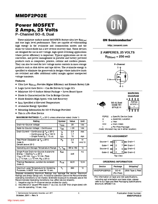
TJ, Tstg EAS
RqJA
−55 to 150 245 62.5
°C mJ
°C/W
Maximum Lead Temperature for Soldering
TL
Purposes, 0.0625″ from case for 10 sec.
Drain−1 Drain−1 Drain−2 Drain−2
ORDERING INFORMATION
Device
Package
Shipping†
MMDF2P02ER2G SO−8 2500 Tape & Reel (Pb−Free)
†For information on tape and reel specifications, including part orientation and tape sizes, please refer to our Tape and Reel Packaging Specifications Brochure, BRD8011/D.
RDS(on)
gFS
Ciss Coss Crss
td(on) tr
td(off) tf
td(on) tr
td(off) tf QT Q1 Q2 Q3
VSD trr ta tb QRR
Min
Typ
Max Unit
25
−
−
2.2
Vdc
−
−
mV/°C
mAdc
−
−
1.0
−
−
10
−
−
100 nAdc
得力 P2000系列激光打印机 P2000D、P2000DW、P2000DN 说明书
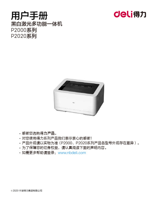
©2020 宁波得力集团有限公司感谢您选购得力产。
品力产品对您使用得力系列产品我们表示衷心的感谢!为了保障您的切身权益,请认真阅读下面的声明内容。
产品外观请以实物为准(P2000、P2020系列产品各型号外观存在差异)。
如需更多帮助请登录:用户手册P2000系列P2020系列黑白激光多功能一体机·“ ”表示支持,“ ”表示不支持。
··如有产品系列增加或变更,恕不另行通知。
产品各型号功能简介(型号功能对照表)本说明书中的产品图片都以P2000DNW为例,由于机型不同可能出现外形不同。
* 根据ISO/IEC 19752标准打印A4纸张。
关于废旧机器与耗材的回收得力集团有限公司作为一家具有社会责任感的企业,为了倡导绿色环保,以及为可持续发展作献,您购买的本公司生产的打印设备及耗材在需废弃时,可交由本公司进行免费回收处理,详细如下:1、您可以拔打得力集团全国服务热线400-185-0555进行登记确认,并按服务热线提供的地址将这些废弃物交到或寄送到得力集团就近的分部或得力集团服务中心。
按照共同有责共同负担的原则,该环节所发生的运费等相关费用由交付者自行承担。
2、得力集团各分部将回收的废弃物统一送回集团服务中心,再由集团服务中心按照国家环境保护法相关法律规定交由具备国家认可资质的回收单位进行专业回收和处理。
该环节所发生的运费、回收处理费等费用由得力集团有限公司承担。
关于零配件(组件)、耗材提供本打印机停产后,部分零配件(组件)、耗材(鼓粉盒)还会提供5年。
关于产品放置的建议建议您将本产品放置于相对通风和独立的区域。
关于使用再生纸的建议为节约资源,促进绿色环保,您也可以使用品质稳定的再生纸。
关于零能耗的建议本产品只有关闭电源开关才能实现零能耗。
目录介绍 ................................................................................................................................................................. 注意事项及安全..................................................................................................................................... 关于本用户手册..................................................................................................................................... 一般安全信息......................................................................................................................................... 设备安放的位置 ..................................................................................................................................... 电气安全 ................................................................................................................................................. 保修 ......................................................................................................................................................... 碳粉盒 ..................................................................................................................................................... 维修保养................................................................................................................................................. 激光的安全性 ......................................................................................................................................... 无线电干扰 ............................................................................................................................................. 警告 ...................................................................................................................................................................................... 概述 ................................................................................................................................... 打印机前视图 ......................................................................................................................................... 打印机后视图 ......................................................................................................................................... 控制面板 ................................................................................................................................................. LED指示灯状态......................................................................................................................................... 按键 ............................................................................................................................................................................................... LED工作状态和错误指示灯的含义 ................................................................................... 首次使用 ....................................................................................................................................................... 1. 拆开打印机的包装....................................................................................................................... 2. 安装碳粉盒 .. (01)0101010202030303040404050505050606070808083. 将纸张装入纸盒 ................................................................................................................................104.打开电源 ...........................................................................................................................................11首次设置 . (12)安装打印机驱动程序 .......................................................................................................................... 12连接设备 .. (12)USB连接 ....................................................................................................................................... 12网络连接 (13)下载移动应用程序(使用“得力e+”App ) .............................................................................................. 14打印机助手使用 . (15)1. 设备管理 ...........................................................................................................................................152.设置 ...................................................................................................................................................163.打印列表 ...........................................................................................................................................164.维护 ...................................................................................................................................................175.购买 ...................................................................................................................................................176.支持 ...................................................................................................................................................177.扫描 ...................................................................................................................................................178.无线连接 . (18)将纸张装入纸盒 ................................................................................................................................... 打印设置 . (19)布局 ................................................................................................................................... ................................................................................................................................... 19纸张 /质量 .. (20)扩展功能............................................................................................................................................... 20高级设置............................................................................................................................................... 21Web 界面 (22)确认IP 地址......................................................................................................................................... 22调用Web 界面 . (22)一、设备状态 (23)二、设备配置..................................................................................................................................... 23三、网络 ............................................................................................................................................. 24四、订购耗材 (26)五、固件更新 (26)六、登录密码....................................................................................................................................... 26维护 .. (26)更换碳粉盒 ........................................................................................................................................... 26故障排除 ............................................................................................................................................... 29卡纸处理 .................................................................................................................................................................. 35改善打印质量 (37)附录 (43)材料安全数据表(MSDS) (43)产品规格............................................................................................................................................... 43....................................................................................................................... 31LCD信息以及LED工作状态清除设备内的卡纸 .............................................................................................................................. 35清除设备后部(定影单元)的卡纸 ...................................................................................................36................................................................................................................35清除纸盒内的卡纸..............................打印介质 ......................................................................................................................... 打印介质的规格 .................. (181818)操作设备前,请仔细阅读以下说明,并根据需要进行参考,确保设备的持续安全运行。
GP2D05中文资料
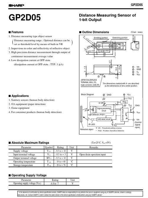
4.4to 7VCC (Ta=25˚C, V =5V)V CC -0.3to +10V V in-0.3to +3V BV O -0.3to +10V T opr-10to +60˚C T stg˚C(Unit : mm)FeaturesApplicationsAbsolute Maximum RatingsParameterSymbol Rating UnitRating Unit Operating Supply VoltageOutline DimensionsSupply voltageInput terminal voltage Output terminal voltage Operating temperature Storage temperatureGP2D05Distance Measuring Sensor of 1-bit OutputParameterRemarksOpen drain operation input1. Distance measuring type object sensorDistance measuring range : Optional distance can be set as threshold level by means of built-in VR2. Impervious to color and reflectivity of reflective object 1. Sanitary sensors (human body detection)2. OA equipment (paper detection)3. Game equipment4. For consumer products (human body detection)3. High precision distance measurement through output of continuous measurement average value ()-20to +704. Low dissipation current at OFF-state(dissipation current at OFF-state : TYP. 3µA)Operating supply voltage (Vcc)data books, etc. Contact SHARP in order to obtain the latest version of the device specification sheets before using any SHARP's device.”“In the absence of confirmation by device specification sheets, SHARP takes no responsibility for any defects that occur in equipment using any of SHARP's devices, shown in catalogs,s s s s s(Ta=25˚C,Vcc=5V)Electro-optical CharacteristicsSymbol MIN.TYP.MAX.Unit Distance measuring range 10-80cm Output terminal voltage V OH V CC -0.3--V V OL --0.3V --I CC -mA -38µA I vinVin =0V-µADistance characteristics of output Average dissipation current Dissipation current at OFF-state Iccoff Vo *1,*3Output voltage at Low, *1Output voltage at High, *1*1,*2*4*5cm 22-1601024L : Distance to reflective objectParameterConditionsVin terminal current-270*1 Reflective object : White paper (reflectivity : 90%)*2 Adjustment shall be available with the VR built in the sensor so that the output switching distance may be L=24 cm.*3 Distance measuring range on conditions after adjustment of the output switching distance to L=24*4 Average dissipation current measured on the conditions shown below*5 Dissipation current when Vin terminal is in High (current OFF) state.*6 Vin terminal : Open drain drive input.Conditions : Vin terminal current at Vin OFF-state >=2.6VVin terminal current at Vin ON-state <= 0.2VTiming Chart∆L Distance measuring operation starts sFig. 1 Distance Measuring Output vs. Distance to Reflective ObjectFig. 2 Detection Distance vs. Sensing RangeSensing range X (mm)D e t e c t i o n d i s t a n c e L (c m )D e t e c t i o n d i s t a n c e L (c m )Illuminance (lx)D i s t a n c e m e a s u r i n g o u t p u tTest Method for Sensing Range CharacteristicsTest Method for Anti External Disturbing Light CharacteristicsReflective object (reflectivity : 90%)Fig. 3 Detection Distance vs. IlluminanceSensing range X (cm)。
GP2S24中文资料
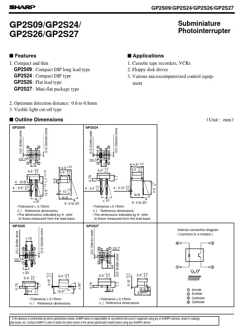
PhotointerrupterSubminiature 1. Compact and thinGP2S26:Flat lead typeGP2S27:Mini-flat package type 2. Optimum detection distance:0.6 to 0.8mm 3. Visible light cut-off type2. Floppy disk drives3. Various microcomputerized control equip- ments Outline Dimensions(Unit :mm )s Featuress Applications1. Cassette tape recorders, VCRs GP2S24GP2S09GP2S09/GP2S24/GP2S26/GP2S27:Compact DIP long lead type :Compact DIP types Absolute Maximum Ratings(Ta =25˚C )The hatched area more than in the figure below.GP2S26The hatched area more than edges of package as shown in the figure below.GP2S27Soldering areaThe hatched area more than edges of package as shown in the figure below.GP2S09, GP2S241mm ∗2 away from the lower ∗1 Within 5 seconds (Soldering areas for each model are shown below )0.5mm away from the both Parameter Rating Unit InputForward current 50mA Reverse voltage 6V Power dissipation75mW OutputCollector-emitter voltage 35V Emitter-collector voltage 6V Collector current20mA Collector power dissiipation 75mW Total power dissipation 100mW Operating temperature -20 to +85˚C Storage temperature -40 to +100˚C ∗1Soldering temperature260˚CSymbol I F V R V CEO V ECO I C P C P tot T opr T stg T solP edge of package as shown 2.0mm away from the both Soldering area:Soldering area:-25025*********0102030405060025-25020*******P o w e r d i s s i p a t i o n P (m W )501007580100855505101525300010020030040050060070020025-250204060801001205010075246810012Fig. 1 Forward Current vs. Ambient TemperatureF o r w a r d c u r r e n t I F (m A )Ambient temperature T a (˚C )Ambient temperature T a (˚C )F o r w a r d c u r r e n t I F (m A )C o l l e c t o r c u r r e n t I C Forward current I F (mA)C o l l e c t o r c u r r e n t I C (µA )Collector-emitter voltage V CE (V )Ambient temperature T a (˚C )Fig. 3 Forward Current vs. Forward VoltageForward CurrentFig. 2 Power Dissipation vs. Ambient TemperatureAmbient TemperatureFig. 4 Collector Current vs. (µA )R e l a t l v e c o l l e c t o r c u r r e n t I C (%)Fig. 6 Relatlve Collector Current vs.I F =4mA V CE =2VV CE =2V T a =25˚CP totP, P C2525252751005025 00.020.050.010.10.10.20.5 1 25100.20.5125 20 50 1000.111010010000.10.2 1 20.5 5 10 20 501002005001000Input0124580 100406020030248010040602061357Fig. 7 Collector Dark Current vs. Ambient TemperatureC o l l e c t o r d a r k c u r r e n t I (A )Ambient temperature T a (˚C )5 10%%R e l a t i v e c o l l e c t o r c u r r e n t (%)Card moving distance L (mm )Fig.11 Relative Collector Current vs.Fig.10 Relative Collector Current vs.Distance between Sensor and Al Evaporation Glass10-1010-910-810-710-6(GP2S24/GP2S26/GP2S27)d =1mm C E O R e s p o n s e t i m e (µs )R e l a t i v e c o l l e c t o r c u r r e n t (%)V CE =2V Test Circuit for Response TimeV CE =20VV CE =2V I C =100µA T a =25˚C t rt ft dt sI F =4mA V CE =2V T a =25˚CDistance between sensor and Al evaporation glass d (mm )I F =4mA T a =25˚CV CE =2V I C =100µA T a =25˚Ct rt ft dt sCard Moving Distance (1)(GP2S09)R e s p o n s e t i m e (µs )Fig. 8 Response Time vs. Load ResistanceLoad resistance R L (k Ω)Fig. 9 Response Time vs. Load ResistanceLoad resistance R L (k Ω)0---- 80406020Fig.12 Relative Collector Current vs.R e l a t i v e s e n s i t i v i t y (%)R e l a t i v e c o l l e c t o r c u r r e n t (%)Wavelength λ (nm )Test Condition for Distance & Detecting Position V o l t a g e g a i n A V (d B )。
DE2中文说明书--第1部分

第一章:关于工具包DE2工具包提供了使用Altera Cyclone II开发高级数字产品需要的所有模块。
此用户指南能使读者在30分钟内迅速浏览许多参考设计。
本章提供了工具包的关键信息。
工具包内容图1.1给出了DE2的图片。
DE2工具包包括以下部分:✓DE2开发板✓用于FPGA编程和控制的USB电缆✓DE2 实验光盘,包括DE2控制面板,参考设计,软件工具以及用户指南✓Altera Quartus II 5.0 网络光盘和Nios II 5.0 光盘✓附件包一个,内含:铜质支架,螺钉,橡皮脚若干✓装配在主板上的树脂玻璃一片✓9V直流Wall-mount电源图1.1. DE2 工具包组装橡皮脚用户可以使用附件袋中的铜脚,硅片和螺丝按照自己的项目组装合适的支架脚。
在DE2板上为每个6螺洞组装螺丝,铜脚和橡胶片,如图1.2所示。
如果需要额外的保护可以装上树脂玻璃片图1.2 橡皮脚安装方式获得帮助遇到问题可以从下几处获取帮助:发邮件至:support@中国台湾& 中国大陆: +886-3-550-8800韩国& 日本: +82-2-512-7661第二章:DE2开发板这一个章节将带你浏览DE2板上的每个部分及其特性DE2开发板DE2开发板使用了与大批量生产的高端产品(如最高QC标准的高密度PC主板和汽车infotainment系统)相一致的严格设计与布线准则。
主要的设计和布线思路如下所示:仔细安排器件及连接走线。
这种良好的排版可增加制造产量,并简化主板调试流程。
无跳线设计提高鲁棒性。
跳线易出错而且为不随时携带手册的用户带来不便。
部件的选择取决于片上容量。
我们选择了在PC 和DVD播放器中最常用的配置确保这些部件将来能够得到持续供应。
电源和IO口保护设计考虑到了大部分的现场意外情况。
开发板检测按图2.1测试开发板图2.1 DE2开发板组件及接口特性DE2主板为用户提供了用于多媒体开发的多种特性。
GPP02 操作手册

鍵可退出設定狀態而回到測量狀態。 (11) 在設定狀態時按 DOWN 鍵爲功能表切換或參數之位移切換
9
鍵,即在進入功能表選擇或參數選擇時,每按一次該鍵就出 現下一條功能表或參數。依次循環。該鍵在參數調整狀態下 爲參數字位移鍵,此時每按一次鍵修改位向下移一位。 (12) 在顯示狀態按 U P 鍵可切換溫度/測量值(pH 或 ORP)顯示, 顯示溫度時℃指示燈同時亮;顯示測量值時℃指示燈同時熄 滅。U P 鍵爲功能表和參數之向上切換鍵,即在進入功能表 選擇或參數選擇時,每按一次該鍵就出現上一條功能表或參 數。依次循環。該鍵在參數調整狀態下爲參數調整鍵,用 DOWN 鍵確認參數位置後,每按一次該鍵該位參數值增 1, 依次循環。在最高為調整參數時,顯示值除 0~9 外還有“-”、 “-1”。有些程式只有末位元參數需設定時,無需移位鍵,直 接按該鍵依次選擇或修改。 (13) ENTER 鍵爲確認鍵,用於確認進入功能表和存儲所設定之
圖 4 接線端子示意圖 接線端子接線說明: 1. 標準配置爲 pH(ORP)電極輸入正極 2. 備用 3. 溫度元件 PT100 輸入端 4. pH(ORP)電極輸入负極、溫度元件 PT100 輸入端 5. 4~20mA 電流輸出端(+極)
4
6. 4~20mA 電流輸出端(-極) 7. 備用 8. 備用 9. 備用 10. 繼電器报警输出公共端(COM) 11. 備用 12. 上限繼電器报警输出端(常开端 NO) 13. 下限繼電器报警输出端(常开端 NO) 14. 備用 15. 備用 16. 備用 17. 備用 18. 備用 19. pH(ORP)電極輸入 BNC 插座 (G) 接地端:接大地 (L2) 備用 (L1) 電源供電端:接 AC110~220V (N) 電源供電端:接電源中相 ★ 注意:
GIANT Power Halo 2 产品说明书

|ES|Manual de usuario de GIANT Power HaloINTRODUCCIÓNLe felicitamos por la compra del nuevo GIANT Power Halo! El nuevo GIANT Power Halo es un potenciómetro de araña compatible con diferentes platos que aporta información precisa en tiempo real gracias a un sistema integrado preciso, fiable y fácil de configurar.El entrenamiento más eficaz es el que se realiza con cabeza, por lo que… ¡Empiece a entrenar con energía!PARTES DEL PRODUCTO❶INDICADOR LED❷PUERTO MAGNÉTICO DE CARGA ❶❷CABLE DE CARGACada Power Halo incorpora un cable especializado de carga. Asegúrese de que este cable se incluya con la compra del Power Halo.Tenga en cuenta que el cargador USB no viene incluido.INDICADORES LEDHay un indicador LED en cada Giant Power Halo. Este indicador puede mostrar diferentes condiciones. Al encender Power Halo girando la biela hacia atrás dos o tres vueltas completas:●El indicador luminoso parpadea en color VERDE 10 veces :la carga de la batería es superior al 60 %●El indicador luminoso parpadea en color NARANJA 10 veces :la carga de la batería está entre el 30 y el 60 %●El indicador luminoso parpadea en color ROJO 10 veces :la carga de la batería es inferior al 30 %Durante la carga:●La luz del indicador luminoso es ROJA : carga en curso.●La luz del indicador luminoso es VERDE : carga completada.El indicador luminoso no muestra luz alguna:Es posible que la batería esté dañada o que haya algún problema en la unidad. Póngase en contacto con un distribuidor autorizado de Giant para que le ayude.AVISO IMPORTANTE ANTES DE MONTAR EN BICICLETALe recomendamos encarecidamente que lea el manual del propietario de la bicicleta en su totalidad antes de montar por primera vez en la bicicleta. Lea todos los puntos de este manual y asegúrese que los comprende, especialmente la sección “Seguridad”. Si tiene alguna pregunta, póngase en contacto con su distribuidor autorizado de Giant.Este manual del usuario contiene información de seguridad, rendimiento y servicio importante. Lea el manual del usuario antes de comenzar a utilizar su nuevo Giant Power Pro y guárdelo por si tiene que consultarlo en el futuro.Por su seguridad, le recomendamos que centre la atención en los alrededores mientras monta en bicicleta. Evite mirar a la pantalla de la bicicleta o del móvil. Esta acción puede hacerle que pierda la atención en el tráfico, lo que podría provocar un accidente grave.SERVICIO DE ATENCIÓN AL CLIENTE Y SOPORTE TÉCNICOSi tiene problemas o no está seguro de alguna de las cosas mencionadas en este manual de usuario, póngase en contacto con el distribuidor autorizado de Gianto visite https:///global/power-haloPara obtener más información, visitehttps:///global/manualsPara encontrar un proveedor u obtener más información acerca de Giant, visite INICIO RÁPIDO1. CARGA DE LA BATERÍAConecte el cable de carga al puerto USB. Si desea obtener resultados mejores, le recomendamos que utiliza un cargador USB específico con una corriente de salida de 1 o 2 A.Conecte el cable al puerto de carga del GIANT Power Halo. La unidad deberá empezar a cargarse de inmediato.Cargue totalmente la batería del Power Halo antes de utilizarlo por primera vez.La luz del indicador luminoso es ROJA : carga en curso.La luz del indicador luminoso es VERDE : carga completada.!PRECAUCIÓVoltaje: 5 V ± 10 %Corriente: 1~2 ATiempo de carga: aprox., 1 hora para carga completa.La baterí2. EMPAREJAMIENTO CON LA COMPUTADORA DE CICLISMO O LA APLICACIÓN RIDELINK APPGIANT Power Halo es compatible con computadoras de ciclismo que incorporen funcionesBLUETOOTH y ANT+, además de la capacidad de registrar información sobre la potencia.1. Gire las bielas totalmente dos o tres veces hacia atrás para reactivar el Giant Power Halo.2. El indicador luminoso parpadea para mostrar el estado de la batería.3. Consulte el manual de usuario de la computadora de ciclismo para asociarla a PowerHalo. Los procedimientos de emparejamiento pueden diferir entre diferentes marcas.También puede emparejar Power Halo con la aplicación GIANT RIDELINK App a través de su móvil.El procedimiento es similar.1.Descargue e instale la aplicación GIANT RIDELINK App de Google Play (Android) o AppStore (iOS)2.Gire las bielas totalmente dos o tres veces hacia atrás para reactivar el Giant Power Halo.3.El indicador luminoso parpadea para mostrar el estado de la batería.4.Siga las instrucciones de la aplicación GIANT RIDELINK App para emparejarla a PowerHalo.3. CALIBRACIÓN Y DESFASE DE CERO DE POWER HALOSi desea obtener mejores resultados, le recomendamos que lleve a cabo la calibración antes de montarse en la bicicleta.Antes de proceder a la calibración, mantenga la biela derecha en la posición más alta del pedaleo y la bicicleta en horizontal. Fije la biela.No intente proceder a la calibración si está montado en la bicicleta. No aplique fuerza sobre los pedales.Consulte el manual de usuario del fabricante de la computadora de ciclismo para calibrarla con Power Halo. Los procedimientos pueden diferir en función de las marcas de la computadora.Si va a utilizar la aplicación RideLink App, siga las instrucciones que se le mostrarán para llevar a cabo la calibración.Durante la calibración, el indicador luminoso parpadea en color AZUL un par de veces.Si realiza la calibración correctamente, podrá ver un mensaje de confirmación «Correcto» o «0» en la computadora. Ya puede disfrutar de un pedaleo con ENERGÍA!APLICACIÓN RIDELINK APPGiant sigue desarrollando y comercializando versiones actualizadas de firmware para proporcionar las funciones más recientes. El firmware más reciente de Giant Power Halo se puede actualizar mediante la aplicación Giant RideLink App.La aplicación Giant RideLink está disponible para sistemas Apple® iOS y Android. Vaya a App Store o Google Play para buscar la aplicación Giant RideLink y descárguela.ESPECIFICACIONESDistancia entre los tornillos de anclaje del plato (BCD) 107 mmBiela compatible SRAM DUB, montaje directo, 8 pernos Conexiones (BLE/ANT+) BLE/ANT+Tipo de batería Batería de ion de litioDuración de la batería 100 horasTiempo de carga de la batería 1 horaIndicador de carga de la batería (Sí o No) SíPrecisión ±1,5 %Compensación de batería SíEquilibrio izquierda-derecha (Sí o No) SíAplicación de firmware RideLinkCapacidad de impermeabilización IPX7Uso previsto Ciclismo sobre terrenos de gravilla o encarreteraMANTENIMIENTO E IMPERMEABILIDADPara garantiza las funcionalidades de Giant Power Halo sin que la garantía limitada de Giant se vea afectada, asegúrese de cumplir las ADVERTENCIAS y PRECAUCIONES que se indican a continuación. El incumplimiento de estas recomendaciones puede provocar daños en el Giant Power Halo e invalidar la garantía.El nivel de impermeabilidad de Giant Power Halo cumple con el estándar IPX7.!ADVERTENCIANO sumerja el Power Halo en agua.NO utilice lavadoras de alta presión para limpiar el medidor de potencia directamente. La alta presión provocará que la humedad penetre en las partes internas del medidor de potencia y dañe los componentes electrónicos.PRECAUCIÓEl intervalo de temperatura ambiente de almacenamiento está comprendido entre -30 y 80 °C (-22 y 176 °F). Se pueden producir daños en los componentes electrónicos si la temperatura de almacenamiento está fuera de este intervalo.GARANTÍA LIMITADA DE GIANTGiant garantiza su potenciómetro durante un periodo de dos (2) años desde la fecha de compraúnicamente para el propietario original. Esta garantía se aplica exclusivamente a este producto adquirido nuevo en un distribuidor autorizado Giant y montado por el distribuidor en el momento de la compra.1. DERECHOS Y ACCIONES LIMITADOSExcepto que se indique lo contrario, las únicas acciones a las que da derecho esta garantía, o cualquier garantía implícita, quedan limitas a la sustitución de piezas defectuosas por aquellas de igual valor o superior a entera discreción de Giant. Esta garantía se extiende a partir de la fecha de la compra, solo se aplica al propietario original y no es transferible. En ningún caso, Giant será responsable por daños directos, accidentales o derivados, incluidos, entre otros, lesiones personales, daños a la propiedad o pérdidas económicas, tanto basadas en contrato, garantía, negligencia, responsabilidad del producto o cualquier otra teoría.2. EXCLUSIONES2.1. La garantía anterior, o cualquier garantía implícita, no cubre:●El desgaste normal y la rotura de piezas en situaciones en las que no haya defectos demontaje o de los materiales.●Los componentes consumibles incluyen los tornillos y el cable de carga.●Los productos no suministrados por un distribuidor autorizado Giant.●Modificaciones del estado original del producto.●El uso de este producto para actividades anormales, competitivas y/o comerciales o confines distintos al uso previsto de dicho producto.●Los daños causados por no seguir el Manual del usuario.●Los daños en el acabado de la pintura y en las pegatinas provocados por la participación encompeticiones, saltos, descensos y/o entrenamientos de dichas actividades o eventos, niaquellos que resulten de exponer o usar el producto a condiciones o climas extremos.●Los gastos de mano de obra por sustitución o cambio de piezas.2.2. Excepto o en lo que se proporciona en esta garantía y sujeto a todas las garantíasadicionales, Giant y sus empleados y agentes no asumirán ninguna responsabilidad por ninguna pérdida o daño, sea el que fuere, (incluidas pérdidas o daños incidentales y consecuentescausados por negligencia u omisión) que se produzca a causa de cualquier producto de Giant o esté relacionado con este.|ES| POWER HALO11 2.3. Giant no ofrece ninguna otra garantía, ni expresa ni implícita. Todas las garantías implícitas, incluyendo las garantías de comerciabilidad e idoneidad para cualquier fin particular limitan suduración a la indicada en las anteriores garantías expresas.2.4. Cualquier reclamación contra esta garantía deberá tramitarse a través de un distribuidorautorizado Giant. Para poder procesar una reclamación de garantía necesitará el recibo decompra o cualquier otra prueba de la fecha de compra. Las reclamaciones realizadas fuera delpaís de compra pueden estar sujetas a tasas y restricciones adicionales.2.5. La duración y los detalles de la garantía pueden variar en función del país. Esta garantía leconfiere unos derechos legales específicos y, dependiendo del país, podrá ostentar ademásotros derechos. ESTA GARANTÍA NO AFECTA A SUS DERECHOS LEGALES .。
Mossberg 802 Plinkster 0.22 L.R. 短筒枪支说明书

CATALOGO DE ARMAMENTO PARA FINES CINEGÉTICOS Y DEPORTIVOS.
TIPO: ESCOPETA SEMIAUTOMATICA - MARCA: MOSSBERG
ESCOPETA SEMIAUTOMATICA CALIBRE 12 G.A. MARCA MOSSBERG MODELO 930, (WATERFOWL MAX-4),
TIPO: RIFLE - MARCA: MOSSBERG RIFLE CALIBRE 0.22" L.R. MARCA MOSSBERG MODELO 802 PLINKSTER,
DE CERROJO, CAÑON DE 18" DE LONGITUD, ACABADO PAVON, CAJA SINTETICA COLOR NEGRO CODIGO: 37045. CON CARGADOR DE SERVICIO CON CAP. DE 10 CARTUCHOS, MIRA TELESCOPICA 4X20, 1 CANDADO, MANUAL Y GARANTIA.
CATALOGO DE ARMAMENTO PARA FINES CINEGÉTICOS Y DEPORTIVOS.
ARMAS LARGAS
CATALOGO DE ARMAMENTO PARA FINES CINEGÉTICOS Y DEPORTIVOS.
Calibre: 0.22"
CATALOGO DE ARMAMENTO PARA FINES CINEGÉTICOS Y DEPORTIVOS.
Clave: AL00108
ESCOPETA CALIBRE 12 G.A. MARCA MOSSBERG MODELO 500, (ALL PUPOSE FIELD),
Schneider Electric TeSys GV2 产品数据手册说明书
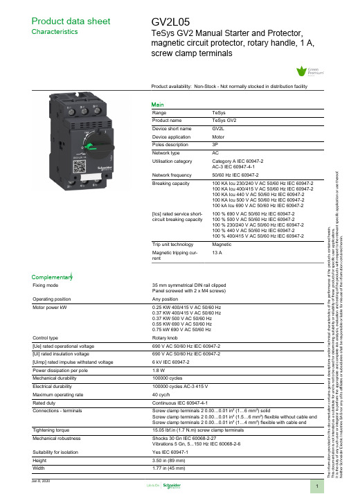
T h e i n f o r m a t i o n p r o v i d e d i n t h i s d o c u m e n t a t i o n c o n t a i n s g e n e r a l d e s c r i p t i o n s a n d /o r t e c h n i c a l c h a r a c t e r i s t i c s o f t h e p e r f o r m a n c e o f t h e p r o d u c t s c o n t a i n e d h e r e i n .T h i s d o c u m e n t a t i o n i s n o t i n t e n d e d a s a s u b s t i t u t e f o r a n d i s n o t t o b e u s e d f o r d e t e r m i n i n g s u i t a b i l i t y o r r e l i a b i l i t y o f t h e s e p r o d u c t s f o r s p e c i f i c u s e r a p p l i c a t i o n s .I t i s t h e d u t y o f a n y s u c h u s e r o r i n t e g r a t o r t o p e r f o r m t h e a p p r o p r i a t e a n d c o m p l e t e r i s k a n a l y s i s , e v a l u a t i o n a n d t e s t i n g o f t h e p r o d u c t s w i t h r e s p e c t t o t h e r e l e v a n t s p e c i f i c a p p l i c a t i o n o r u s e t h e r e o f .N e i t h e r S c h n e i d e r E l e c t r i c I n d u s t r i e s S A S n o r a n y o f i t s a f f i l i a t e s o r s u b s i d i a r i e s s h a l l b e r e s p o n s i b l e o r l i a b l e f o r m i s u s e o f t h e i n f o r m a t i o n c o n t a i n e d h e r e i n .Product data sheetCharacteristicsGV2L05TeSys GV2 Manual Starter and Protector,magnetic circuit protector, rotary handle, 1 A,screw clamp terminalsProduct availability: Non-Stock - Not normally stocked in distribution facilityMainRange TeSys Product name TeSys GV2Device short name GV2L Device application Motor Poles description 3P Network type ACUtilisation category Category A IEC 60947-2AC-3 IEC 60947-4-1Network frequency 50/60 Hz IEC 60947-2Breaking capacity100 KA Icu 230/240 V AC 50/60 Hz IEC 60947-2100 KA Icu 400/415 V AC 50/60 Hz IEC 60947-2100 KA Icu 440 V AC 50/60 Hz IEC 60947-2100 KA Icu 500 V AC 50/60 Hz IEC 60947-2100 kA Icu 690 V AC 50/60 Hz IEC 60947-2[Ics] rated service short-circuit breaking capacity100 % 690 V AC 50/60 Hz IEC 60947-2100 % 500 V AC 50/60 Hz IEC 60947-2100 % 230/240 V AC 50/60 Hz IEC 60947-2100 % 440 V AC 50/60 Hz IEC 60947-2100 % 400/415 V AC 50/60 Hz IEC 60947-2Trip unit technology Magnetic Magnetic tripping cur-rent13 AComplementaryFixing mode 35 mm symmetrical DIN rail clipped Panel screwed with 2 x M4 screws)Operating position Any positionMotor power kW0.25 KW 400/415 V AC 50/60 Hz 0.37 KW 400/415 V AC 50/60 Hz 0.37 KW 500 V AC 50/60 Hz 0.55 KW 690 V AC 50/60 Hz 0.75 kW 690 V AC 50/60 Hz Control typeRotary knob[Ue] rated operational voltage 690 V AC 50/60 Hz IEC 60947-2[Ui] rated insulation voltage690 V AC 50/60 Hz IEC 60947-2[Uimp] rated impulse withstand voltage 6 kV IEC 60947-2Power dissipation per pole 1.8 W Mechanical durability 100000 cyclesElectrical durability 100000 cycles AC-3 415 V Maximum operating rate 40 cyc/hRated dutyContinuous IEC 60947-4-1Connections - terminalsScrew clamp terminals 2 0.00…0.01 in² (1…6 mm²) solidScrew clamp terminals 2 0.00…0.01 in² (1.5…6 mm²) flexible without cable end Screw clamp terminals 2 0.00…0.01 in² (1…4 mm²) flexible with cable end Tightening torque 15.05 lbf.in (1.7 N.m) screw clamp terminals Mechanical robustness Shocks 30 Gn IEC 60068-2-27Vibrations 5 Gn, 5...150 Hz IEC 60068-2-6Suitability for isolation Yes IEC 60947-1Height 3.50 in (89 mm)Width1.77 in (45 mm)Depth 3.82 in (97 mm)Net weight0.73 lb(US) (0.33 kg)EnvironmentStandards EN/IEC 60947-2EN/IEC 60947-4-1CSA C22.2 No 60947-4-1UL 60947-4-1Product certifications IECEE CB SchemeULCSACCCEACRINALROS (Lloyds register of shipping)DNV-GLBVProtective treatment THIP degree of protection IP20 IEC 60529IK degree of protection IK04Ambient air temperature for operation-4…140 °F (-20…60 °C)Ambient air temperature for storage-40…176 °F (-40…80 °C)Fire resistance1760 °F (960 °C) IEC 60695-2-1Operating altitude0...6561.68 ft (0...2000 m)Ordering and shipping detailsCategory22367 - MANUAL STR PROTECTOR - GV2Discount Schedule I11GTIN00785901218050Package weight(Lbs)0.27 kg (0.6 lb(US))Returnability NoCountry of origin FROffer SustainabilitySustainable offer status Green Premium productREACh Regulation REACh DeclarationEU RoHS Directive Compliant EU RoHS DeclarationMercury free YesRoHS exemption information YesChina RoHS Regulation China RoHS DeclarationEnvironmental Disclosure Product Environmental ProfileCircularity Profile No need of specific recycling operationsWEEE The product must be disposed on European Union markets following specificwaste collection and never end up in rubbish bins.Contractual warrantyWarranty18 monthsProduct data sheetGV2L05Performance CurvesTripping Curves for GV2L or LE Combined with Thermal Overload Relay LRD or LR2K Average Operating Times at 20 °C Related to Multiples of the Setting Current1 3 poles from cold state2 2 poles from cold state3 3 poles from hot stateCurrent Limitation on Short-Circuit for GV2L and GV2LE Only (3-Phase 400/415 V) Dynamic StressI peak = f (prospective Isc) at 1.05 Ue = 435 V1Maximum peak current232 A325 A418 A514 A610 A7 6.3 A84 A9 2.5 A10 1.6 A11Limit of rated ultimate breaking capacity on short-circuit of GV2LE (14, 18, 23, and 25 A ratings).Current Limitation on Short-Circuit for GV2L and GV2LE + Thermal Overload Relay LRD or LR2K (3-Phase 400/415 V)Dynamic StressI peak = f (prospective Isc) at 1.05 Ue = 435 V1Maximum peak current232 A325 A418 A514 A610 A7 6.3 A84 A9 2.5 A10 1.6 A11Limit of rated ultimate breaking capacity on short-circuit of GV2LE (14, 18, 23, and 25 A ratings). Thermal Limit on Short-Circuit for GV2L OnlyThermal Limit in kA2s in the Magnetic Operating ZoneSum of I2dt = f (prospective Isc) at 1.05 Ue = 435 V125 A and 32 A218 A314 A410 A5 6.3 A64 A7 2.5 A8 1.6 AThermal Limit on Short-Circuit for GV2L and GV2LE + Thermal Overload Relay LRD or LR2K Thermal Limit in kA2s in the Magnetic Operating ZoneSum of I2dt = f (prospective Isc) at 1.05 Ue = 435 V132 A (GV2LE32)225 A and 32 A (GV2L32)318 A414 A510 A6 6.3 A74 A8 2.5 A9 1.6 A10Limit of rated ultimate breaking capacity on short-circuit of GV2 LE (14, 18, 23, and 25 A ratings).Product data sheetGV2L05Dimensions DrawingsGV2LDimensionsX1 Electrical clearance = 40 mm for Ue ≤ 415 V, or 80 mm for Ue = 440 V, or 120 mm for Ue = 500 and 690 V. X2 = 40 mm.GVAD, AM, AN, AU, AS1MaximumGV2AK00MountingOn rail AM1 DE200, AM1 ED200 (35 x 15)Panel mountedOn pre-slotted mounting plate AM1 PAAdapter Plate GK2AF017.5 mm Height Compensation Plate GV1F03MountingMounting of External Operator GV2APN01, GV2APN02 or GV2APN04 for Motor Circuit Breakers GV2LDoor cut-out(1)For IP65 only.Mounting of External Operator GVAPH02 for Motor Circuit Breakers GV2LDoor cut-out(1)For IP65 only.GV2L and GV2LESets of busbars GV2G445, GV2G454, GV2G472, with terminal block GV2G05Sets of Busbars for GV2L and GV2LESets of busbars GV2G●●● with terminal block GV1G09Sets of busbars GV2G245, GV2G254, GV2GR272Set of busbars GV2G554Sets of busbars GV2G345 and GV2G354Product data sheetGV2L05 Connections and SchemaGV2L••。
Schurter PG02熔断器保护熔断器块与夹子说明书
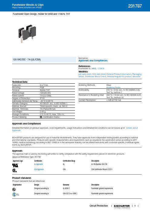
1231787Circuit ProtectionFuseholder Open Design, Holder for MSB and 172876, THTSee below:Approvals and Compliances 125 VAC/DC · 7 A (UL/CSA)References Fuseholder to MSB ; 172876Weblinkspdf data sheet , html data sheet , General Product Information , Packaging details , Distributor-Stock-Check , Detailed request for product , MicrositeT echnical DataFuse-Link 2 x 7 mm Mounting PCBTerminalSolder THT Rated Voltage 125 VAC/DC Rated current7 A (UL /CSA)Degree of ProtectionIP 00Admissible Ambient Air Temp.-40 °C to 85 °CClimatic Category 40/085/21 acc. to IEC 60068-1Material: Socket Thermoplastic, black, UL 94V-0Material: Terminals Tin-Plated Bronze Unit Weight0.45 gStorage Conditions 0 °C to 60 °C, max. 70% r.h.Product Marking, Certification marksSoldering Methods WaveSoldering ProfileSolderability235 °C / 2 sec acc. to IEC 60068-2-20, Test Ta, method 1Resistance to Soldering Heat 260 °C / 10 sec acc. to IEC 60068-2-20, Test Tb, method 1A Contact Resistance< m Ω at 100 mAApprovals and CompliancesDetailed information on product approvals, code requirements, usage instructions and detailed test conditions can be looked up in Details about ApprovalsSCHURTER products are designed for use in industrial environments. They have approvals from independent testing bodies according to national and international standards. Products with specific characteristics and requirements such as required in the automotive sector according to IATF 16949, medical technology according to ISO 13485 or in the aerospace industry can be offered exclusively with customer-specific, individual agree-ments by SCHURTER.ApprovalsThe approval mark is used by the testing authorities to certify compliance with the safety requirements placed on electronic products. Approval Reference T ype: 231787Approval LogoCertificates Certification Body DescriptionUL Approvals UL UL File Number: E41738CSA ApprovalsCSACSA Certification Record: 23151Product standardsProduct standards that are referencedOrganizationDesignStandard DescriptionDesigned according to UL 4248-1Fuseholder general requirements Designed according toCSA C22.2 no. 4248.1Fuseholder general requirements2231787Circuit ProtectionApplication standardsApplication standards where the product can be usedOrganizationDesignStandardDescriptionDesigned for applications acc.IEC/UL 60950IEC 60950-1 includes the basic requirements for the safety of information technology equipment.CompliancesThe product complies with following Guide LinesIdentificationDetailsInitiator DescriptionSCHURTER AGThe CE marking declares that the product complies with the applicable requirements laid down in the harmonisation of Community legislation onits affixing in accordance with EU Regulation 765/2008.RoHS SCHURTER AG EU Directive RoHS 2011/65/EUChina RoHS SCHURTER AG The law SJ / T 11363-2006 (China RoHS) has been in force since 1 March2007. It is similar to the EU directive RoHS.REACHSCHURTER AGOn 1 June 2007, Regulation (EC) No 1907/2006 on the Registration, Evaluation, Authorization and Restriction of Chemicals 1 (abbreviated as "REACH") entered into force.Dimension [mm]10 mmDrilling diagramAll Variants Packaging Unit.xx = .03 Plastic Bag (100 pcs.).xx = .55 Blister Tape (500 pcs.)The specifications, descriptions and illustrations indicated in this document are based on currentinformation. All content is subject to modifications and amendments. Information furnished is believed to be accurate and reliable. However, users should independently evaluate the suitability and test each product selected for their own applications.13.02.2019。
OMEGA PD2-DIO 64 128 位数数字输入输出模块说明书

ߜ64 or 128 Lines (5V/TTL) of I/O in 16-Bit PortsߜGenerate Interrupts on Any LineߜFour Separate High-Speed IRQ Lines (100 nS)ߜCustom Logic ChipReplaces Obsolete 8255sand EquivalentsߜIdeal for Solid-StateRelaysߜUser-Defined Power-Up State in 16-Bit Groups(High, Low, Tri-stated)ߜTwo EnhancedSynchronous SerialInterfaces (ESSIs) forHigh-Speed Devices Such as CodecsߜOnboard Buffer Size: 2k SamplesߜThree 24-BitCounter/TimersߜDetects Incorrect orShorted Wiring For applications that involve a high number of digital I/O lines, OMEGA offers two models in the PD2-DIO family with either 64 or 128 I/O lines. Instead of following the industry trend of implementing discrete I/O with cumbersome and limiting 8255-type devices, we work with 16-bit line drivers under control of a DSP and custom logic.As a result, you no longer need to create external circuitry to guarantee power-on startup states; our software allows you to configure startup states in groups of 16-bit ports. You no longer need to design separate interrupt circuitry; our hardware comes with four high-speed interrupts waiting for you to use. The digital I/O lines are protected against electrostatic discharge and automatically detect shorts on power up.Besides digital I/O, the board features three 24-bit counter/timers as well as two high-speed ESSI (Enhanced Synchronous Serial Interface) ports. The onboard DSP and optimized PCI-bus interface also allow the card to optionally stream digital data to or from disk at rates as high as 2 MB/S.PowerDAQ II PCI DIO Boards Digital Input/Output BoardsBasic Unit $395Distribution panels make all theboard's I/O capabilities available forfield connection. Further, anoptional accessory (PD2-DIO-CONN64-4) distributes 64 of thedigital I/O points into four sets of 16lines through industry-standard 50-pin IDC connectors. They, in turn,attach directly to relay panelsavailable from UEI and many othersources.SoftwareThe PowerDAQ II includes acomprehensive software suiteprovided at no additional charge. Thesuite consists of a menu driven quickstart application for quick and easyoperation without programming, asoftware development kit (SDK) forcustom user program creation underWindows 9x/NT/2000 and softwaredrivers for a large variety of off-the-shelf applications. The quick startapplication provides data collection,graphical display of the data, anddatalogging in a format compatiblewith most spreadsheets and otherpost acquisition software packages.The PowerDAQ II SDK supportsVisual C++, Visual Basic, Delphiand Borland C++ BuilderPowerDAQ II Digital I/O boards arealso compatible with a variety of off-the-shelf data acquisition applicationprograms. The drivers for thefollowing packages are provided atno charge.Third Party Drivers for:LabVIEW for WindowsHP VEETestPointDASYlabDIAdemShown smaller than actual sizeD3-7D3-8DIGITAL I/O AND COUNTER/TIMER CARDSSpecificationsOutput Drive Characteristics Output Drive Current V O = 2.5V Result: -32 mA per pin -180 mA per portOutput High Voltage I OH = -3 mA Result: 3.5V typ 4.8V max Output High Voltage I OH = -15 mA Result: 3.5V typ 4.7V max Output High Voltage I OH = -32 mA Result: 2.4V min 3.0V typ Output Low Voltage I OL = 64 mA Result: 0.2V typ 0.55V max I/O Power Off LeakageV I/O ≤4.5VResult: ±1 µA maxDC Electrical Characteristics Over Operating Range Input High Level Guaranteed LogicHigh Level Result: 2.0V minInput Low Level Guaranteed LogicLow Level Result: 0.8V maxInput High Current V I = 5V Result: ±1 µA max Input Low Current V I = Gnd Result: ±1 µA max 3-State Output Current V O = 2.7V Result: ±1 µA max 3-State Output Current V O = 0.5V Result: ±1 µA max Short-Circuit Current V O = Gnd Result: -80 mA min;(momentary)-140 mA typ; -250 mA maxInput Hysteresis Result: 100 mV typ ESSI Characteristics The Motorola 56301 DSP contains two fast enhanced synchronous serial interfaces.The PowerDAQ II DIO board allows access to both.Each ESSI port contains threetransmitters and one receiver and has a maximum operational speed of 15Mbits/S.PD2-DIO-CBL-100PD2-DIO-STP-64PD2-DIO-CONN64-4Ordering Example:PD2-DIO-64PowerDAQ II board, PD2-DIO-STP-64 terminal panel (includes cable) and OMEGACARE SM 1 year extended warranty for PowerDAQ II board (adds 1 year to standard 1 year warranty), $395 + 150 + 39 = $584Counter/TimerNumber of Channels Three Resolution24 bitsMaximum Frequency 16.5 MS/s for external clock and 33 MS/s for internal DSP clockMinimum Frequency 2 S/s for internal clock, no low limits for external clock Minimum Pulse Width 20 nSOutput High Level 2.0V min @ -4 mA Output Low Level 0.5 max @ 4 mA Protection 7 kV ESD, + 30 VOvershoot/Undershoot Input Low Voltage 0.0 - 0.8 V Input High Voltage2.0 - 5.0 VCANADA www.omega.ca Laval(Quebec) 1-800-TC-OMEGA UNITED KINGDOM www. Manchester, England0800-488-488GERMANY www.omega.deDeckenpfronn, Germany************FRANCE www.omega.frGuyancourt, France088-466-342BENELUX www.omega.nl Amstelveen, NL 0800-099-33-44UNITED STATES 1-800-TC-OMEGA Stamford, CT.CZECH REPUBLIC www.omegaeng.cz Karviná, Czech Republic596-311-899TemperatureCalibrators, Connectors, General Test and MeasurementInstruments, Glass Bulb Thermometers, Handheld Instruments for Temperature Measurement, Ice Point References,Indicating Labels, Crayons, Cements and Lacquers, Infrared Temperature Measurement Instruments, Recorders Relative Humidity Measurement Instruments, RTD Probes, Elements and Assemblies, Temperature & Process Meters, Timers and Counters, Temperature and Process Controllers and Power Switching Devices, Thermistor Elements, Probes andAssemblies,Thermocouples Thermowells and Head and Well Assemblies, Transmitters, WirePressure, Strain and ForceDisplacement Transducers, Dynamic Measurement Force Sensors, Instrumentation for Pressure and Strain Measurements, Load Cells, Pressure Gauges, PressureReference Section, Pressure Switches, Pressure Transducers, Proximity Transducers, Regulators,Strain Gages, Torque Transducers, ValvespH and ConductivityConductivity Instrumentation, Dissolved OxygenInstrumentation, Environmental Instrumentation, pH Electrodes and Instruments, Water and Soil Analysis InstrumentationHeatersBand Heaters, Cartridge Heaters, Circulation Heaters, Comfort Heaters, Controllers, Meters and SwitchingDevices, Flexible Heaters, General Test and Measurement Instruments, Heater Hook-up Wire, Heating Cable Systems, Immersion Heaters, Process Air and Duct, Heaters, Radiant Heaters, Strip Heaters, Tubular HeatersFlow and LevelAir Velocity Indicators, Doppler Flowmeters, LevelMeasurement, Magnetic Flowmeters, Mass Flowmeters,Pitot Tubes, Pumps, Rotameters, Turbine and Paddle Wheel Flowmeters, Ultrasonic Flowmeters, Valves, Variable Area Flowmeters, Vortex Shedding FlowmetersData AcquisitionAuto-Dialers and Alarm Monitoring Systems, Communication Products and Converters, Data Acquisition and Analysis Software, Data LoggersPlug-in Cards, Signal Conditioners, USB, RS232, RS485 and Parallel Port Data Acquisition Systems, Wireless Transmitters and Receivers。
【精品】工业2完整版说明书资料

工业2完整版说明书资料——————————————资源篇——————————————————1.新增基础矿物:铜矿:在地下70层到10层可以找到,大多用来制造铜电缆和青铜(比例15:10)锡矿:在地下40层以下可以找到,大多用来制造好用的电池和空槽铀矿:64层以下就可以找到的矿物,用途只有1个 = = 就是发电2.非矿物类新增基础资源:橡胶树:这玩意的树干--------看起来像屎黄色.但橡胶树是工业中最重要的资源,如果没有它,你根本无法进行下一步。
你可以拿木龙头来采集橡胶,到后期可拿提取机来提取粘性橡胶。
————————————基础矿物篇——————————————————————本章主要介绍各种工业的矿锭钢:这个东西是由铁锭在炉子中烧成的,制成机器的必备品铜:这个东西是由铜矿或者铜粉烧制而成的,主要用来制作电缆锡:这个矿是由锡矿或者锡粉烧成的,主要用来制作电池或者空槽(尤其是电池,这玩意在初期很有用)青铜:这玩意是工业之路上必须要的(扳手要),但与其他矿不同,这个不是挖到的,是合成出来的,合成步骤:1.先把铜矿和锡矿打粉(要打粉机然后再烧)2.再这样子合成青铜粉:3.再烧青铜粉,你就得到青铜了铀锭:这个东西在初期,或者不玩核电的话,就是废柴1个(但玩起来,可非常危险,如果造核电站设计内部GUI,需要用到这货,记住穿上防化服和橡胶靴)获得方法:将铀矿放进压缩机,你就得到铀锭了_________________________基础工具篇____________________________________________本章主要介绍初期到中期的可合成工具青铜工具系列:这些工具的耐久度大于铁1点(350次),但是速度没铁快合成方法跟铁或者黄金工具差不多,这里只用稿子举例:青铜装备系列:与工具一样,耐久度多了30%,算是不错的:(合成方法跟其他装备1样,用胸甲举例)当然,青铜的最大用处是扳手:扳手算是工业中最重要的工具之一!因为,你觉得拿稿子去拆机器会得到机器?做梦去吧!那只会得到碎片!可惜,虽然有扳手,但还是有4分之一的可能性手残(拆成机器方块)不过这玩意有耐久,你也可以把扳手升级为电动扳手,那样就只用充电了。
- 1、下载文档前请自行甄别文档内容的完整性,平台不提供额外的编辑、内容补充、找答案等附加服务。
- 2、"仅部分预览"的文档,不可在线预览部分如存在完整性等问题,可反馈申请退款(可完整预览的文档不适用该条件!)。
- 3、如文档侵犯您的权益,请联系客服反馈,我们会尽快为您处理(人工客服工作时间:9:00-18:30)。
GP2D02
V CC
4.4to 7
V
Compact, High Sensitive Distance Measuring Sensor
(Unit : mm)
Features
Symbol
Rating Unit Operating Supply Voltage
Outline Dimensions
*1 Open drain operation input
s s s
(Ta=25˚C,Vcc=5V)
Electro-optical Characteristics
Note) L : Distance to reflective object
*1 Reflective object : White paper (reflectivity : 90%)
*3 Vin terminal : Open drain drive input.
Conditions : Vin terminal current at Vin OFF-state : -1µA
Vin terminal current at Vin ON-state : 0.3V
*2 Average dissipation current value during distance measuring operation when detecting of input signal, Vin as shown in the timing chart Test Circuit
1. Test circuit
2. Vin input signal for measurement
8-bit serial output read
V signal input in
DEC : Decimalized value of sensor output (8-bit serial)Parameter
Symbol Conditions
MIN.TYP.
MAX.
Unit Distance measuring range ∆L *110-80cm Output terminal voltage V OH Output voltage at High L =20cm *1
V CC -0.3--V V OL Output voltage at Low --0.3V Distance characteristics of output D L =80cm, *1
-75-DEC ∆D Output change at L=80 cm to 20 cm, *1485868DEC Dissipation current at operating I CC L =20cm, *1, *2-2235mA at OFF-state
I off L =20cm, *1-38µA Vin terminal current
I vin
Vin =0V --170
-280
µA
s s
Fig. 1 Distance Measuring Output vs.
Timing Chart
D i s t a n c e m e a s u r i n g o u t p u t (D
E C )
Distance to reflective object L (cm)
s
Fig. 3 Detection Distance vs. Illuminance
D e t e c t i o n d i s t a n c e L (c m )
Illuminance (lx)
Test Method for Anti External Disturbing Light Characteristics
Test Method for Sensing Range Characteristics
Reflective object Fig. 2 Detection Distance vs. Sensing Range
D e t e c t i o n d i s t a n c e L (c m )
Sensing range X (mm)
(reflectivity : 90%)
01020304050607080
901000
102030405060
70
80
90100。
