PT系列触控屏安装向导
图解完美安装触摸屏

很多人拥有这样的设备和技术,而我这里是免焊接,人人都会简单至极老少咸宜方便到爆……大家的口水出来没有?那么,let’s do it!首先,当然是去买个触摸屏(废话),目前寸触摸屏生产厂家不是太多,本人是在淘宝上购买的390元的免焊接触摸屏套件来看看,极致轻薄~先来小小普及一下,触摸屏并不是一些人误认为的可以代替屏幕的,它本身只是一层透明玻璃板或者压克力板,内有压力感应膜,通过触摸使触摸点的压力发生变化,从而使电阻发生改变,达到识别操作的目的。
所以触摸屏是安装在屏幕上滴!~(知道的人请无视)好了,首先,我们必须拆机,拆得彻底,所以顾忌保修的同志们,欣赏一下就好了哈~~~开始拆,首先当然是把电池拆下来,然后把底部所有的螺丝都卸了,注意螺丝别弄丢了然后翻过来,咱们拆键盘,键盘的拆解不要使用蛮力,在键盘上方缝隙有3个可见的口子,分别在~与F1之间的上方、F6的上方以及F12的上方,只需用螺丝批轻轻一推,就能将键盘掀起来了,要注意键盘的下方连接着排线,不要用力过猛扯断了~将排线拔离后,就看到了负责散热的金属板,上边有6颗螺丝,和令人郁闷的保修封条,含泪都卸了!卸完后将触摸板的排线也拔了。
当拔了排线后不要急,这里暗藏危机……首先在机器的两边有扳子的暗扣,用指甲或者吉他拨片一类的东西插入两边的缝隙,从前往后推,阻力大不用担心,用力就是了,随着几声清脆的啪啪声,暗扣就解开了,这时慢慢抬起,你就会发现,左边又有一条线连着主板,这是快捷键的插口,小心把它拔了后,就可以把板子整个拿起了~大家可以看到芯片上面都有粘胶,这是将热量导至金属板之用。
在主板上我们可以看到……蓝牙模块~~!还有一个大大的901logo~~由于到后面我们需要把主板翻过来,所以首先,把主板上方的两颗螺丝(左右各一颗)给卸了(那个箭头不是我的哈)然后需要将风扇的插头拔了将扬声器的插头也拔了这时主板已经可以拿起了,但是我们先不要这么做,还是继续拆完再说~接下来要拆的是屏幕了!首先把胶垫用螺丝批撬下来,露出了里边的螺丝下边的装饰垫也小心弄下来然后当然就是把螺丝全部卸下来咯!继续用指甲或之类的东西插进边缘,暴力啊~~~不过不会有伤害的~把屏幕框拿下来,由于右下角有线连着,我们就让它躺在主板上就行了。
触摸屏安装及调试方案

触摸屏安装及调试方案1. 概述本文档旨在提供触摸屏安装及调试方案,确保正确安装和有效运行触摸屏设备。
以下是该方案的步骤和注意事项。
2. 环境准备在开始安装和调试触摸屏之前,请确保您具备以下所需的环境和设备:- 触摸屏设备及其附件- 笔记本电脑或计算机- 笔尖或者其他软绘图工具- 相应的驱动程序和软件3. 安装步骤请按照以下步骤进行触摸屏设备的安装:1. 准备工作:将计算机或笔记本电脑关机,并确保触摸屏设备的电源已关闭。
2. 连接触摸屏:根据触摸屏设备的连接接口,选择正确的连接线缆,并将其插入计算机或笔记本电脑的对应接口。
3. 固定触摸屏:使用提供的安装支架或螺丝将触摸屏设备固定在所需位置。
4. 打开电源:打开计算机或笔记本电脑的电源,并同时开启触摸屏设备的电源。
5. 驱动程序安装:根据设备提供的说明书,安装相应的触摸屏驱动程序和软件。
6. 完成安装:根据安装程序的指引,完成触摸屏设备的安装。
4. 调试步骤一旦触摸屏设备成功安装,您可以按照以下步骤对其进行调试:1. 检查触摸功能:使用提供的笔尖或其他软绘图工具,在触摸屏上进行简单的操作,如点击、滑动等,以确保触摸功能正常。
2. 校准触摸屏:如果触摸屏在使用过程中存在准确度问题,您可以运行触摸屏设备附带的校准程序,校准触摸屏的坐标和精度。
3. 测试应用程序:打开您需要使用触摸屏的应用程序,检查触摸屏设备是否与应用程序兼容,并确保其正常工作。
4. 故障排除:如果在调试过程中遇到触摸屏设备无响应或其他问题,请查阅设备的说明书或联系供应商以获得进一步的支持或修复。
5. 结论通过按照本文档中提供的安装和调试方案进行操作,您应该能够正确安装和调试触摸屏设备,并确保其正常运行。
如遇到任何问题或疑问,请及时与设备供应商或技术支持团队联系,以获得进一步的帮助和支持。
祝您安装成功!。
PT531 商务彩屏电话 说明书
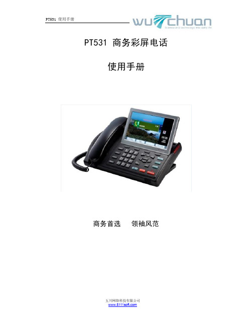
PT531 商务彩屏电话使用手册商务首选领袖风范目录一.功能概括 (3)1.1注意事项 (3)二.安装指引 (3)2.1设备检查 (3)2.2电话连接方法 (4)三.基本功能使用简介 (4)3.1 听筒与免提 (5)3.2 铃声调节 (5)3.3 免提音量调节 (5)3.4 听筒音量调节 (6)3.5 拨打电话 (6)3.6 接听来电 (6)3.7 静音(Mute)与保持(Hold) (6)3.8 使用双线Line1或Line2 (6)3.9 三方会议通话。
(7)3.10 留言等待 (7)3.11 夜晚模式 (7)四.高级功能使用简介 (7)4.1 来去电查询 (8)4.2 电话簿 (8)4.3号码帖 (10)4.4 通话录音 (10)4.5 录音播放及U盘转存 (10)五.主菜单功能简介 (11)5.1 时间设置 (11)5.2 USB文件交换 (12)5.3存储键 (13)5.4 问候语 (14)5.5 显示屏设置 (14)5.6 电话功能设置 (15)5.7 语言选择 (15)5.8高级功能设置 (15)六.多媒体功能简介 (16)6.1照片浏览 (16)6.2音乐播放 (16)6.3录音机 (17)6.4日历及计算器 (17)一、功能概括u环保低功耗整体设计u高品质大音量免提通话u支持三方会议功能的双线电话(一部电话可同时连接两条电话线,例如:直线和分机)u可转动的7寸数字TFT彩色显示屏,支持中文姓名显示/来电显示u字母检索式600条中文电话簿u150条来去电记录(包括已接,未接,已拨)u独立的音量调节,静音,电话保留,挂机按键u长达300小时的电话录音(存储于U盘),u数字式电子相框u背景音乐/MP3音乐播放功能u夜晚自动时钟显示模式u商务助理—万年历,计算器,录音笔u停电时仍可接听及打出电话u来电显示时(FSK 方式),话机时间自动校准。
1.1注意事项u请勿在潮湿的环境中使用,勿将水滴溅到电话上。
图形操作终端安装手册说明书
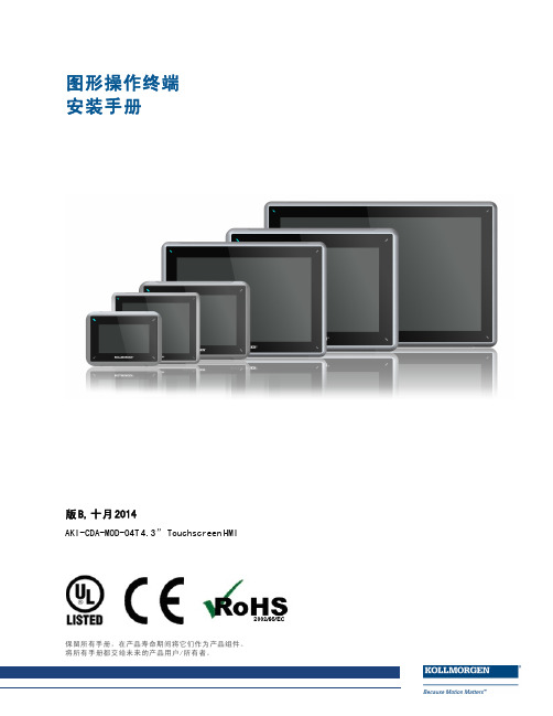
图形操作终端安装手册版B,十月2014AKI-CDA-MOD-04T4.3”Touchscreen HMI保留所有手册,在产品寿命期间将它们作为产品组件。
将所有手册都交给未来的产品用户/所有者。
文档修订记录修订版本备注A,07/2013早期版本B,10/2014更新的UL信息硬件修订版本修订版本固件修订版本软件修订版本备注06/2013b0917 2.0-SP1初始版本10/2014b0920 2.10重要通知如有提升设备性能的技术变更,恕不另行通知!美国印刷本文档知识产权归所有。
版权所有。
未经书面许可,不得以任何形式(利用影印、缩微胶片或任何其他方法)复制本文档的任何部分,也不得利用电子手段存储、处理、复制或分发本文档的任何部分。
AKI-CDA-MOD-04T|目录1常规措施1.1关于本手册 (4)2安全防护措施2.1常规措施 (5)2.2UL和cUL安装: (5)2.3安装期间 (6)2.4使用期间 (6)2.5维修和维护 (7)2.6拆除和废弃处置 (7)2.7触摸屏中出现空气 (7)3安装3.1空间要求 (8)3.2安装过程 (9)3.2.1与控制器的连接 (10)3.2.2其他连接和外设 (10)4技术数据5耐化学性5.1金属外壳 (13)5.2触摸屏和涂层 (14)5.2.1Autoflex EBA180L (14)5.2.2触摸屏表面 (14)5.2.3触摸屏幕保护膜 (15)6操作面板图纸6.1连接器 (16)6.2通信端口 (16)6.3AKI-CDA-MOD-04T结构图 (17)7额外安装提示7.1操作面板接地 (18)7.2操作面板中的以太网连接 (19)7.3实现更好的EMC保护 (20)7.4环境温度 (20)7.5安全性 (22)7.6电流隔离 (23)7.7电缆和总线终端RS485 (23)AKI-CDA-MOD-04T|常规措施1常规措施1.1关于本手册所有Advanced Kollmorgen Interfaces的开发宗旨均是满足人机通信的需要。
触摸屏驱动软件安装方法
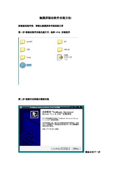
触摸屏驱动软件安装方法:
按装驱动程序前,请确认触摸屏信号线连接正常
第一步:将驱动程序安装光盘打开, 选择setup 安装程序.
第二步:根据对话框提示继续安装
鼠标点击下一步
鼠标点击我接受
选择安装
最后点击完成。
请重新启动计算机。
第三步:触摸屏校正程序
用鼠标点击出现以上菜单
选择菜单第一项,点击控制界面选项,进入控制界面首页
选择工具选项
点击进阶定位开关按钮
使其按钮颜色变成黄色,打开成功。
返回控制界面首页,选择设定按钮进行触摸屏定位矫正。
进入四点校正界面
用手指或校正笔压住红点进行校正,如校正时未压准红
点,有可能产生漂移,建议校正时尽量压准红点。
用手指或校正笔压住红点进行校正,如校正时未压准红点,有可能产生漂移,建议校正时尽量压准红
点。
用手指或校正笔压住红点进行校正,如校正时未压准红点,有可能产生漂移,建议校正时尽量压准红
点。
用手指或校正笔压住红点进行校正,
如校正时未压准红点,有可能产生漂
移,建议校正时尽量压准红点。
点击保存退出。
校正完成,任意点一下,退出。
PT-60 移动数据终端 说明书

使用手册PT-60移动数据终端目录第一章简介 (3)1. Argox PT-60(枪型) & 附件 (3)1.1 Argox PT-60 外观 (4)1.2 CRD-20 充电座外观 (5)2.Argox PT-60 使用前的准备 (6)2.1 安装标准型电池 (6)2.2安装枪型握把电池 (7)2.3使用触控笔 (8)2.4安装SD卡 (8)3. Argox PT-60 第一次操作 (8)3.1 冷开机 (8)3.2 校准PT-60 (8)4. Flash 内存 (9)第二章键盘与扫描器 (10)1.键盘 (10)1.1Alpha键 (12)1.2功能键 (13)1.3软件键盘 (14)2.使用CCD扫描器 (15)第三章电源 (16)1.充电/供电 (16)2.电源指示状态 (17)3.检查电池状态 (17)3.1进入电池管理 (17)3.2检查电源状态 (17)4.热启动 / 冷启动 (18)4.1热启动 (18)4.2冷启动 (18)5. 开关机 (18)5.1 开关机 (18)5.2 开关机灯号显示 (18)第四章通讯 (19)1.指示灯 (19)1.1充电座电源 (19)1.2充电座充电指示灯 (19)2.数据通讯 (19)2.1使用RS-232传输线(选配) (19)2.2使用USB传输线(标准配置) (20)2.3使用CRD-20通讯充电座(选配) (20)3.安装Microsoft ActiveSync (21)4.无线通讯 (25)5.蓝牙通讯 (28)第五章应用程序 (33)1. Scanner Demo (33)2. 扫描设置 (33)附录A 技术参数 (34)第一章简介感谢您使用 PT-60。
PT-60 是一个小巧的复合型的移动数据终端,使用Windows CE® 操作系统,整合了条形码的扫描读取设备,彩色触控屏幕,键盘,无线通讯功能,为用户操作提供标准的WINDOWS 界面。
触摸屏安装说明
触摸屏安装说明提纲一.触摸屏的简要介绍和安装准备1. 通用的四线电阻触摸屏的特点;2. 电阻触摸屏的安装准备;3. 安装电阻触摸屏的注意事项;二.触摸屏的安装1. 触摸屏的安装过程;2. 触摸屏的驱动软件安装;3. 触摸屏的硬件安装;三.触摸屏的具体使用方法和注意事项四.排除故障的要点总结1 触摸屏的简要介绍和安装准备1.1 通用的四线电阻触摸屏的特点;最近几年,人机对话的界面刚发展起来的一项新技术,它通过计算机技术四线/触摸屏控制处理声音、图像、视频、文字、动画等信息,并在这些信息间建立一定的逻辑关系,使之成为能交互地进行信息存取和输出的集成系统。
触摸屏系统符合简便、经济、高效的原则,具有人机交互性好、操作简单灵活、输入速度快等特点。
它与迅猛发展的计算机网络和四线/触摸屏控制多媒体技术相结合,使用者仅仅用手指触摸屏幕,就能进行信息检索、数据分析,甚至可以做出身临其境、栩栩如生的效果;较键盘输入简单、直观、快捷,具有丰富多采的表现能力,比以往任何传媒更具亲合力。
触摸屏在我国已经得到了非常广阔的应用,主要是公共信息的查询;如电信局、税务局、银行、电力等部门的业务查询;城市街头的信息查询;此外应用于领导办公、工业控制、军事指挥、电子游戏、点歌点菜、多媒体教学、房地产预售等。
如今,触摸屏特别是电阻式触摸屏,在不断走入大众家庭。
,四线电阻式触摸屏:电阻触摸屏的屏体部分是一块与显示器表面非常配合的多层四线/触摸屏控制复合薄膜,由一层玻璃或有机玻璃作为基层,表面涂有一层透明的导电层,上面再盖有一层外表面硬化处理、光滑防刮的塑料层而内表面也涂有一层透明导电层,在两层导电层之间有许多细小(小于千分之一英寸)的透明隔离点把它们隔开绝缘,见图1。
图1 四线电阻触摸屏的基本原理当手指触摸屏幕时,平常相互绝缘的两层导电层就在触摸点位置有了一个接触导通,因其中一面导电层接通Y纵轴方向的参考电压Vref=5v 均匀电压场,使得侦测层的电压由零变为非零,控制器侦测到这个接通后,进行模数A/D转换,并将得到的电压值与参考电压Vref相比即可得到触摸点的Y轴坐标,同理得出X横轴的四线/触摸屏控制坐标,这就是所有电阻技术触摸屏共同的最基本原理。
WISE PT600 安装设置手册

PT600安装设置手册PT600控制系统安装设置手册目录目录第一部分系统介绍简介4技术参数4典型应用4设备及配件装箱清单5端口说明6第二部分系统设置系统设置向导软件的安装7系统设置连接8确定设置用串口8选择设置方式9选择被控制设备的控制方式10选择被控制设备型号11RS232串口通信参数设置12被控制设备红外码类别识别13PT600面板按键功能设置14 PT600柜门探测功能设置15系统功能维护16增加功能17被控制设备RS232串口控制指令码设置18被控制设备红外码学习19延时时间设置20组合功能设置21最后一步22设置报告查看22保存设置22数据传输22第三部分设备连接PT600控制系统安装设置手册目录面板与主机连接示意图23 UPS系统连接示意图24投影机、门探连接示意图25计算机信号连接示意图26电动屏幕连接27第四部分技术支持常见故障及解决方法28技术支持途径29第五部分附录PT600面板安装尺寸30技术参数31编程电缆引脚定义32投影机控制接线图32系统功能表33 PT600控制系统安装设置手册第部分系统介绍第一部分系统介绍简介PT600控制系统是专为多媒体投影机设计的一套控制系统。
它与WISE DP700一样具有安装方便、操作简易、高度的稳定可靠、故障率极低等特点。
在功能上作了更进步的简化在信号切换上依靠投影机本身所带端口主要应用在些控制功能要求一步的简化,在信号切换上依靠投影机本身所带端口,主要应用在一些控制功能要求简单的多媒体教室建设中。
主要技术参数1.一路RS232/IR控制接口(复用)2.一路AC220V电源可控制输出(用于投影机供电,延时时间可设定)两路开关量信号探测口3.两路开关量信号探测口(UPS和门锁)4.四键式按键面板(键功能可自由设置)5.一路电动屏幕控制端口6.一路VGA信号输入,两路输出7.一路UPS开关控制端口8.两路电源输入(UPS和市电)典型应用一台具备VIDEO端口和RGB端口的投影机、一台PC机、一台视频展示台-4-PT600控制系统安装设置手册系统设置连接步骤:1、确认PT600主机开关处于OFF 状态。
触摸屏的安装
触摸屏的安装本章告诉你如何将你的普通显示器,安装成触摸显示器。
内容包括:1 如何拆开你的显示器2 在crt上粘贴触摸屏3 安装触摸屏控制器4 连接控制电缆安装前的重要提示:一、如果没有显示器的安装经验,请勿擅自动手,安装显示器是有危险的工作。
二、安装过程必须小心,豪普曼公司不承担由于您安装过程造成的显示器或触摸屏的任何损坏的责任。
三、请务必注意安装说明中的注意事项:1.你需要注意什么本说明书假定你是一个较合格的显示器技术员,而且拆装显示器有一定的经验。
你必须了解你的计算机而且有相应的资料可以参考。
显示器内部存在高压,如果你不了解显示器的电路原理,可能会伤害自己,或者损坏显示器、触摸屏、触摸屏控制卡,请你留意。
1 务必留意安装警告及安全措施,拆装显示器是一个危险的工作。
2 安装前准备足够的元器件及工具,还要准备一个小箱来盛放。
3 准备足够而方便的安装空间。
4 安装前检查你的显示器确保工作正常才可安装触摸屏。
5 熟悉触模屏各部件及其安装过程。
2.警告及安全措施基于以下原因,提醒用户只有熟悉显示器才可以安装触模屏:1 可能对人造成伤害。
2 显示器内有高压。
3 可能伤害crt屏幕。
4 可能影响crt的精密度。
安装之前请准备以下安全措施:1 查询你的显示器生产厂家,确认安装触摸屏后仍能提供产品保证。
2 仔细操作每一步,关闭电源,拔开插座,并看清所有警告。
3 注意!即使拔掉电源,显示器内仍有高压。
4 打开显示器后,及对裸露的crt操作时,保护好你的面部。
眼睛和身体各部位。
5 珍惜你的投资,触摸屏是玻璃制品,注意轻拿轻放。
3.需要准备的物料及工具4.工作场地1 方便的工作场地:足够的空间和照明,建议面积不少于3平方英尺2 防护用品:1/2”的泡泡袋及垫子,垫于台面以免碰伤刮伤设备3 小工具箱:以便放置拆下来的螺丝。
垫片及其它散件。
4 软泡沫:以放置拆下的裸露c盯,以使显象管放置时,后部不被磕碰。
5.显示器测试无论你将触摸屏安装于一个新的显示器或一个正在使用的显示器,安装之前,均需进行测试,保证显示器工作状态良好,图象输出正常,并将装上触摸屏前后的效果进行比较。
PT100系列 智能手持PDA 说明书 (WINCE6.0平台)

PT100系列系列智能手持智能手持PDA用户手册(WINCE6.0平台平台))REV:011003132.1硬件规格硬件规格........................................................................................................................................................4 2.2软件规格软件规格........................................................................................................................................................5 2.3产品详细规格及产品详细规格及性能参数性能参数............................................................................................5 2 应用领域......................................................................................................................................7 3 PT100系统设置:.. (8)3.1外形介绍外形介绍........................................................................................................................................................8 4 功能设置.. (8)4.1 4.1 开机开机..............................................................................................................................8 4.2 4.2 为手持终端充电为手持终端充电..........................................................................................................9 4.3 4.3 手持终端的开关机手持终端的开关机......................................................................................................9 4.4 4.4 手持终端的休眠与唤醒手持终端的休眠与唤醒手持终端的休眠与唤醒................................................................................................................................9 4.5 4.5 电源管理电源管理......................................................................................................................9 4.6 4.6 使用硬件按钮使用硬件按钮............................................................................................................10 4.7 USB 4.7 USB 端口端口....................................................................................................................10 4.8 TF 卡接口卡接口....................................................................................................................................................10 4.9 4.9 串口设置串口设置....................................................................................................................10 4.10 4.10 音频输出音频输出..................................................................................................................10 4.11 4.11 触摸屏使用触摸屏使用..............................................................................................................11 4.12 4.12 设置日期时间设置日期时间..........................................................................................................11 4.13 USB Device 的设置的设置. (12)4.13.1 Activesync............................................................................................................12 4.13.2 Microsoft ActiveSync 与驱动的安装..............................................................12 4.13.3建立连接..............................................................................................................13 4.13.4 文件管理.............................................................................................................14 4.14 4.14 背光调节程序背光调节程序..........................................................................................................15 4.15 4.15 发布用户程序发布用户程序..........................................................................................................15 4.16 4.16 定制开机画面定制开机画面..........................................................................................................16 4.17 WI 4.17 WI--FI 设置程序设置程序. (16)4.18 GPRS 设置程序设置程序 (19)4.19 GPS 设置程序设置程序 (21)4.20条码识读程序条码识读程序 (22)4.21 RFID 识读程序识读程序 (23)4.22 C#4.22 C#演示程序演示程序..............................................................................................................24 5应用程序开发.. (24)5.1 5.1 安装安装Visual Studio 2005 (24)5.1.1安装Visual Studio 2005........................................................................................24 5.1.2安装MSDN...........................................................................................................29 5.1.2 安装Visual Studio 2005 Service Pack 1...............................................................29 5.2 5.2 安装安装SDK SDK......................................................................................................................................................31 5.3 5.3 建立和编译建立和编译VC++VC++应用程序应用程序. (35)5.3.1 新建工程...............................................................................................................35 5.3.2与 SDK 关联........................................................................................................40 5.3.3 编译并下载.. (43)8提供定制服务: (46)提供定制服务:9 硬件保修 (47)9.1 硬件保修时限 (47)9.2 硬件保修范围 (47)1概述PT100系列为我公司生产的基本型PDA,内置GPRS模块,WIFI模块,GPS模块,RFID 模块,一维条形码激光扫描模块。
触摸屏显示器的安装说明
触摸屏显示器的安装说明触摸屏显示器的安装说明触摸屏显示器是一种方便用户进行操作的设备。
在使用触摸屏显示器之前,需要正确地安装它。
本文将为您详细介绍触摸屏显示器的安装步骤和注意事项。
第一步:准备工作在开始安装触摸屏显示器之前,需要做一些准备工作。
首先,确保您拥有适配触摸屏的计算机系统,包括主机、操作系统以及相关驱动程序。
其次,将触摸屏的包装打开,检查是否有任何物品损坏并确保包含所有所需的配件和线缆。
第二步:连接电源将触摸屏显示器的电源线插入电源插座,并确认电源开关处于关闭状态。
然后,将显示器的电源线插入触摸屏显示器的电源接口。
最后,将另一端的电源线插入计算机主机的电源接口。
第三步:信号线连接将触摸屏显示器的信号线插头插入计算机主机的对应接口。
确保插头插入牢固,并紧固螺丝以防止松动。
接下来,将触摸屏显示器的USB线插头插入计算机主机的USB接口。
同样地,确保插头插入稳固,并紧固螺丝以保证连接的牢固性。
第四步:固定底座根据您的需要,选择适当的位置放置触摸屏显示器,并将其底座固定在桌面或其他平稳的表面上。
确保底座稳固且平衡,以避免显示器的晃动或倾斜。
第五步:驱动安装在正式使用触摸屏显示器之前,您需要安装相关的驱动程序。
通过连接计算机与互联网,下载并安装适用于您的操作系统的驱动程序。
根据驱动程序安装向导的指示进行操作,并在安装完成后重新启动计算机。
第六步:调整显示设置启动计算机后,进入操作系统,并打开控制面板。
选择显示设置,确保操作系统正确识别并显示触摸屏显示器。
在需要的情况下,进行屏幕分辨率和方向的调整,以适应您的使用需求。
第七步:功能测试在完成以上所有步骤后,您可以进行功能测试以确保触摸屏显示器的正常工作。
通过轻触屏幕,尝试进行点击、滑动等操作,观察屏幕是否正确响应。
如果发现任何问题,您可以检查连接是否正确、驱动是否安装完整,或者联系销售商或售后服务。
注意事项:- 在安装触摸屏显示器时,请务必断开计算机主机的电源,以避免触摸屏和电脑之间的电气连接。
触摸屏安装步骤

1.把这个文档保存为网页格式保存在桌面上!2.在桌面上生成的是这个机房接地方案33.再打开触摸屏软件里的“8 ”这个软件4.如图5.打开6.打开刚才在桌面上生成的是这个机房接地方案37.点击拆分8.从这一段话开始往上全选如图9.打开触摸屏软件中的新建文本文档10.复制第一段话粘贴在刚才选中的代码点复制粘贴在这个选中的代码12.文件另存为直接保存替换13.这是生成的网页文件14打开你们社区的触摸屏软件,这里以孝南区广场街道办事处为例15.打开文件资料!16.选择你们刚才生成的网页文件复制在你要放的文件夹里面(这里以妇联制度为例)17.打开这个文件复制网址18.打开触摸屏软件中的Access200319.选择第一个20.打开各社区的触摸屏软件这里以孝南区广场街道办事处为例21.选择cxsj.mdb22.点击“否”23.打开24.打开song25.找到妇联制度26.粘贴刚才复制的网址(步骤17)请仔细看图粘贴在什么位置27.如图28.如图29.打开这个1024 查询系统30.完成!关于软件插入图片的步骤以此图为例1.新建一个word文档命名如机房2打开机房文档复制图片在文档如下图(居中)3.文件另存为网页格式打开触摸屏软件“8”4.打开上图这个5.打开机房26.步骤接上8 . 9. 10. 117.打开这个软件之后代码之中有灰色的代码请删除,8.其他步骤都是相同的最后修改完成了的软件,也就是你们要的最终效果的软件,用U盘装到触摸屏复制在D盘,把以前的文件夹覆盖把桌面上以前做成的删除最后把你们完成的软件“1024查询系统dgz”创建一个桌面快捷方式放在桌面把这个快捷方式拖动到开始-所有程序-启动里(把开始-所有程序-启动里面以前的快捷方式删除)完成!。
山特灵霄系列PT 15-20KS UPS使用手册说明书

客服电话:400-830-3938 / 800-830-3938PT 15-20KS UPS 使用手册 USER MANUAL感谢您使用山特产品!请严格遵守本手册中和机器上的所有警告及操作说明,并妥善保管本手册。
在没有阅读完所有的安全说明和操作说明以前,请不要操作UPS。
产品防伪为了切实保障您的用电安全,帮助您购买到真正的山特U PS,请注意以下事项:1. 认准山特注册商标:、、、、。
2. 山特电子(深圳)有限公司在中国从未以任何形式授权委托其它公司生产U PS;3. 山特所有产品机身上均贴有“中国质量检验协会”监制的防伪标签,可拨打电话4006804365或扫描二维码查询验证;4. 山特所有产品机身上均贴有“产品序列号”(产品序列号是唯一的,一个产品对应一个序列号);5. 消费者可以通过以下途径对产品真伪进行鉴别。
山特官网查询查询方式:使用电脑或智能手机(iphone/Android 系统),登陆w ,在左侧导航栏点击防伪查询,依次输入产品序列号和电子监管码进行查询。
如果您购买到有疑问的山特产品,可通过以下途径向本公司反馈1、客服热线:400-830-3938/800-830-39382、品牌保护邮箱:*************************版权声明山特公司致力于技术创新,不断提供更好的产品和服务满足客户需求,对产品设计、技术规格的更新,恕不另行通知。
产品以实物为准。
请到山特网站w 下载最新版的产品说明书。
版权所有© 2019山特电子(深圳)有限公司特殊符号以下是UPS 或附件上的重要符号说明:有触电危险- 请遵守与触电危险符号有关的警告。
务必遵守的重要说明。
请勿将UPS 或电池丢弃到垃圾中。
此产品含有密封铅酸电池,必须按照本手册的说明妥善处理。
如需详细信息,请联络当地的资源回收/再利用或危险废弃物处理中心。
此符号表示您不应将报废的电气或电子设备(WEEE) 丢弃到垃圾中。
Extron TLP Pro 1230WTG 12英寸超宽台式触摸面板安装指南说明书

I M P O R T A NT:.c o mf o r t hel l a t i o nTLP Pro 1230WTG • Setup GuideOverviewThe Extron® TLP Pro 1230WTG is a 12" ultra-wide tabletop touchpanel with a capacitive, edge-to-edge glass touchscreenand a resolution of 1920x720. It has a weighted base that allows it to stand on any suitable table or desktop. It is ideal forany AV applications requiring a large touchpanel with a fully customizable interface. This guide provides instructions forexperienced installers to mount and install the touchpanel. For more complete details, see the TLP Pro 1230WTG User Guide at .Setup Overview and ChecklistGet ReadyDownload and install the latest version of the following software:z GUI Designer — For designing layouts for Extron TouchLink® Pro touchpanels and third party touch interfaces.z Global Configurator® Plus and Professional — For setting up and configuring the control processor and touchpanel.z Global Scripter® — Provides an integrated development environment for Extron control systems programming. Global Scripter provides an Extron-exclusive Python™ library (ControlScript®) and Global Scripter modules to get you started.z Toolbelt — For device discovery, device information, firmware updates, and configuration of network settings, systemutilities, and user management for TouchLink Pro devices.Obtain the following network information from your network administrator:DHCP status (on or off). If DHCP is off, you also require:IP address Subnet mask GatewayUsername — This can be either admin or user.Passwords — The factory configured passwords for all accounts on this device have been set to the device serial number.Passwords can be changed during configuration. Passwords are case sensitive.Make a note of the touchpanel MAC address.Mount and Cable All DevicesMount the units. There are several mounting options for TouchLink Pro touchpanels (see Mounting on page 2).Connect cables to the touchpanels (see Rear Panel and Base Features on page 3).Connect the touchpanel to a power source. These models must be powered by PoE. A power injector must be purchased separately.An Extron IP Link® control processor must be connected to the same Ethernet subnetwork as the touchpanel.Set up the Touchpanels for Network CommunicationConnect the PC that you are using for setup, the control processor, and touchpanel to the same Ethernet subnetwork.Use the Setup Menu (see page 4) or Toolbelt to set the DHCP status and, if necessary, the IP address, subnet mask, gateway, and related settings for the touchpanel.1TLP Pro 1230WTG • Setup GuideConfigure the TouchpanelsCreate a graphical user interface with GUI Designer (see the GUI Designer Help File for step-by-step instructions).Associate functions with the graphical user interface features using Global Configurator or Global Scripter.MountingGo to to see a list of optional mounting kits that are available for this model. The kits must be purchasedseparately. Follow the installation instructions provided with the kit.Desktop MountingThese touchpanels come assembled with stands that allow them to be placed on any suitable flat surface (for example a desk, table, or lectern).Fixed Mounting1. Mark the location for two mounting holes, 4.96 inches (126 mm) apart (see figure 2, B, on page 3).2. Drill two pilot holes into the desktop.3. Insert two #10 flat-head wood screws (not provided) through the touchpanel and align them with the two pilot holes.4. Secure the touchpanel to the tabletop.SMA-1 Swivel Mount AdapterTo permanently mount the touchpanel and swivel it up to 180° in either direction, use the optional Extron SMA-1 swivel mount adapter.1. Attach the conduit, insulation disk, and swivel disk and configure the set screws to allow for the degree of swivel that is required(see the SMA-1 Swivel Mount Adapter Kit User Guide, available at ).2. Place the mounting hole in the base over the conduit of the SMA-1.3. Secure the unit with the backing plate and locking nut as described in the SMA-1 Swivel Mount Adapter Kit User Guide. Front Panel FeaturesFigure 1. TLP Pro 1230WTG Front Panel A Motion sensor (2) — Detects motionbetween three to five feet from thetouchpanel, and at least 15° from thecenter axis.z If the Sleep Timer has been set,and no motion has been detectedfor a user-defined period of time, thetouchpanel enters sleep mode.z If Wake on Motion has been set,and motion is detected by thesensor while the screen is in sleepmode, the screen display is restoredand active.For further information about setting theSleep Timer and Wake on Motion,see the “Setup Menu” section in theTLP Pro 1230WTG User Guide, which isavailable at .B Communication LED — Shows the configuration and connection status of the touchpanel:z Unlit during normal operation (the touchpanel is configured and connected to an IP Link Pro control processor).z Blinks red if the touchpanel has been configured but is not connected to an IP Link Pro control processor.z Lit solidly red if the touchpanel has not been configured.The indicator can be toggled between enabled and disabled, using the Setup Menu (see page 4).C Ambient light sensor — Monitors ambient light level and adjusts screen brightness.D Capacitive touch screen — Provides simple control of AV systems. The TLP Pro 1230WTG has a 12 inch screen with a1920x720 resolution.E Status light — Can be programmed to provide system feedback. The LED light bar is located under the screen.23Rear Panel and Base FeaturesD B H C AI BAE F G Figure 2. TLP Pro 1225TG Rear Panel and BaseA Speakers (2) — For video preview and audible feedback for the user.B Mounting Holes — Used to secure the touchpanel to a desktop or other flat surface (see Desktop Mounting on page 2).C Cable Guide — The LAN/PoE and HDMI cables are inserted through this hole at the back of the base (see “TLP Pro 1230WTGBase Features” in the TLP Pro 1230WTG User Guide ).D LAN/PoE Connector— These touchpanels must be powered by Power over Ethernet (PoE; see “Connecting Power” below).E USB connector — Compatible with USB 2.0. The port is concealed behind a plastic cover, which can be removed with a small,flat-bladed screw driver.F Rear status light — An LED light bar that can be programmed to provide system feedback.G HDMI Connector — A recessed connector for HDMI input.H MENU button — Activates the Setup Menu (see page 4).I RESET button — Pressing the RESET button allows the unit to be reset in any of three different modes and can also be used totoggle between enabling and disabling the DHCP client (see Reset Modes: A Brief Summary on page 4)J RESET LED — Provides feedback about the reset status when the user presses the RESET button (see Reset Modes: A BriefSummary ).Connecting PowerThe TLP Pro 1230WTG must be powered by Power over Ethernet (PoE). The power injector must be purchased separately. The PI 140 is shown in figure 3 on page 4. Your power injector may look different.4For information on safety guidelines, regulatory compliances, EMI/EMF compatibility, accessibility, and related topics, see the Extron Safety and Regulatory Compliance Guide on the Extron website.For information about replacing and disposing of batteries, see the TLP Pro 1230WTG User Guide at .© 2021 Extron — All rights reserved. All trademarks mentioned are the property of their respective owners.Worldwide Headquarters: Extron USA West, 1025 E. Ball Road, Anaheim, CA 92805, 800.633.987668-3147-50 Rev. B03 21TLP Pro 1230WTG • Setup Guide1. Connect a straight-through Ethernet cable from the power injectorto a switch or router. This cable carries network information from the switch or router to the power supply input.2. Connect a second straight-through cable from the power injectorto the PoE/LAN connector of the touchpanel (see figure 2, D , on page 3). This cable carries the network information and 48 VDC from the power injector to the touchpanel.3. Connect the IEC power cord to a convenient 100 VAC to 240 VAC,50-60 Hz power source.Alternatively, use an Ethernet cable to connect the LAN/PoE+ port of the touchpanel to a PoE+ switch.To Network or XTP DevicetouchpanelFigure 3. Connecting the Power InjectorReset Modes: A Brief SummaryThe TLP Pro 1230WTG offers the following reset modes. For complete information, see the TLP Pro 1230WTG User Guide .• Use factory firmware:Use this mode to replace firmware in the event of firmware failure. Press and hold the RESET button (I ) while applying power to the unit.• Reset All IP Settings:Use this mode to reset all network settings without affecting user-loaded files. Press and hold the RESET button for 6 seconds. After the RESET LED (J ) blinks twice (at 3 and 6 seconds), release and momentarily press the RESETbutton.• Reset to Factory Defaults:Use this mode to return the touchpanel to factory default settings, including passwords. Press and hold the RESET button for 9 seconds. After the RESET LED blinks three times (at 3, 6 and 9 • Enable or Disable theDHCP Client:Use this mode to toggle between DHCP enabled and DHCP disabled. Press the RESET button five times, consecutively. After the fifth press, do not press the button again within 3 seconds. If DHCP was enabled, it is now disabled and the RESET LED blinks three times. If DHCP was Setup MenuPress the Menu button (H ) to open the setup menu. Select any of the six available screens (Status , Network , Display , Audio , Input and Advanced ) by tapping the appropriate button in the navigation bar at the top of the screen (for more information, see the TLP Pro 1230WTG User Guide ).Figure 4. Setup Menu: Status Page for TLP Pro 1230WTG。
蓝宝石PT-CI7Z87M-PR安装使用手册说明书

第1章 - 简介 1 1-1 主板规格 1 1-2 包装内容 4 1-3 主板布局 5 1-4 I/O 背板 6 第2章 - 安装8 2-1 安装前的准备工作 8 2-2 安装I/O 挡板8 2-3 固定主板至系统机箱底部 8 2-4 安装CPU 和CPU 散热器 9 2-5 安装系统内存 10 2-6 安装扩展卡 11 2-7 连接线缆 12 2-8 LED 状态指示 15 2-9 主板之板载按钮 16 第3章 - BIOS 的设置 17 3-1 进入BIOS 主界面 17 3-2 控制键位 17 3-3 主题说明17 3-4 Main(BIOS 主界面) 18 3-5 Performance (性能设置) 18 3-6 Advanced(高级BIOS 功能设置) 20 安 装 使 用 手 册 芯片组、LGA1150插槽主板3-8 Security(安全设置) 26 3-9 Exit(退出BIOS设置程序)26第4章– 安装设备驱动器27 TRIXX工具30第1章- 简介1-1 主板规格CPU中央处理器支持最新LGA1150插槽接口的Core i3 / i5 / i7 / Pentium / Celeron系列处理器;支持22nm、Intel®第四代核心系列处理器芯片组Intel Z87芯片组绘图处理芯片Intel® HD图形处理器最大Shared Memory可达1024MB三个板载的显示输出接口、可支持三屏幕显示系统内存4条240针DDR3 DIMM内存扩充槽支持1.5伏DDR3-1066/1333/1600+ MHz双通道内存(non-ECC、unbuffered)最大可达32GB系统内存USB输出接口8个USB 2.0 输出(4个接口在IO背板,4个为主板板载);传输可达480Mbps4个USB 3.0 输出(2个接口在IO背板,2个为主板板载);传输可达4.8GbpsS1、S3和S4模式支持(wake-up)唤醒功能SATA接口Intel® Z87芯片组原生支持:4个SATA3.0接口,传输率达6Gb/s支持RAID 0/1/5/10/AHCI(Advanced Host Controller Interface)板载网卡Realtek 8111系列千兆网络芯片板载声卡Realtek ALC892编码译码器支持7.1声道高保真音效支持板载S/PDIF输出支持音频接口侦测功能扩充插槽1条PCI-Express 3.0 x16扩充插槽1条PCI-Express 2.0 x1扩充插槽1条PCI扩充插槽1条MINI PCIE扩充插槽I/O控制芯片板载NCT5532系列I/O芯片支持硬件监控技术:可侦测风扇转速、CPU及系统温度I/O背板接口1个PS/2键盘鼠标二合一接口1个HDMI接口1个DVI接口1个VGA接口2个USB3.0接口4个USB2.0接口1个RJ45网络接口6孔式音频接口I/O板载接口1个24针ATX 电源接口1个8针ATX 12伏电源接口4个USB 2.0接口2个USB 3.0接口4个SATA 3.0接口1个前置面板接头(FPANEL)1个S/PDIF接头1个前置音源接头(F_AUDIO)1个COM口接头(JCOM1)1个CPU风扇和2个系统风扇电源接头BIOS2个64Mb SPI Flash(以AMI BIOS为基础)支持ACPI(Advanced Configuration and Power Interface)支持双BIOS切换特点蓝宝黑钻电感全固态薄膜电容双BIOS及切换开关8声道高保真音频、SATA 3.0接口电源、重置按钮、LED灯显示CMOS清除按钮Windows硬件监控工具USB 3.0接口I Charge主板尺寸Micro- ATX板型、245 x 220 mm操作系统支持Windows 7和Windows 81-2包装内容蓝宝主板包装盒内,包含以下附件主板此图片为样品,请以实物为准安装手册驱动光盘I/O 挡板SATA 连接线此图片为样品,请以实物为准1-3主板布局下图显示各零件在主板上的位置。
PT1945R PT1945P 触摸屏监视器用户手册说明书

PT1945R / PT1945P Touch Screen MonitorUSER’S GUIDEThe information contained in this document is subject to change without notice.This document contains proprietary information that is protected by copyright. All rightsare reserved. No part of this document may be reproduced,translated to another languageor stored in a retrieval system, or transmitted by any means, electronic, mechanical, photocopying, recording, or otherwise, without prior written permission. Windows is a registered trademark of Microsoft, Inc. Other brand or product names are trademarks of their respective holders.The test results show that this device meets the FCC rules. Those limits are set to protect residential areas from the devices with harmful emission. This device will produce, use and radiate radio frequency energy. In addition, failure to follow the user’s manual to install or use this device might produce harmful interference with radio communication. Not withstanding the foregoing, it does not guarantee that this type of harmful interference does not occur in some special installations. The interference caused by this device to the reception of radio or television signals may be verified by turning it on and off. Any changes or modifications to this TFT LCD would void the user’s authority to operate this device.For more information on how to recycle your product, please visit/GREEN.Table of ContentsUsage NoticePrecautions (1)IntroductionAbout PT1945R/PT1945P (2)Touch Screen for PT1945R .. (3)Touch Screen for PT1945P .. (3)Package Overview (4)InstallationProduct Overview (5)Front View (5)PT1945R Bottom View (Without Stand) (5)PT1945P Bottom View (Without Stand) (5)Start Your Installation (6)Connecting the Display (Figure 8.1) (7)(Figure 8.1) (8)Kensington Security Slot (9)VESA Mount Your Monitor (10)Remove the Deskstand (11)User ControlsSide Panel Controls (12)How to Use the OSD Menus (13)On-Screen Display Menus (14)AppendixTroubleshooting (15)Warning Signal (16)No Signal (16)Going to Sleep (16)Out of Range (16)Product Dimensions (17)PT1945R (17)PT1945P (18)Compatibility Modes (19)Touch Screen Driver Installation (20)PT1945R Optional Calibration Tool Install (20)PT1945P Optional Calibration Tool Install (21)PT1945R Install Instructions (23)PT1945P Driver Install Instructions (25)Technical Support (26)Usage NoticePrecautionsFollow all warnings, precautions and maintenance as recommended in this user’s manual to maximize the life of your unit.Do:• Turn off the product before cleaning.• Touch screen surface may be cleaned using a soft clean cloth moistened withmild window glass commercial cleaners or 50/50 mixture of water and isopropylalcohol.• Use a soft cloth moistened with mild detergent to clean the display housing.• Use only high quality and safety approved AC/DC adapter.• Disconnect the power plug from AC outlet if the product is not going to be used foran extended period of time.Don’t:• Do not touch the LCD display screen surface with sharp or hard objects.• Do not use abrasive cleaners, waxes or solvents for your cleaning.• Do not operate the product under the following conditions:- Extremely hot, cold or humid environment.- Areas susceptible to excessive dust and dirt.- Near any appliance generating a strong magnetic field.- In direct sunlight.IntroductionAbout PT1945R/PT1945PThe PT1945R/PT1945P is a 19" flat panel screen with an active matrix,thin-film transistor (TFT) edge-lit LED liquid crystal display (LCD).This unit is to be used as commercial and light industrial equipment only. Features include:• Direct Analog signal input• Active matrix TFT LCD technology• 1280 x 1024 SXGA resolution• 19" viewable display area• 31.47 ~ 80 KHz horizontal scan• 56 ~ 75 Hz high refresh rate• 0.294mm x 0.294mm pixel pitch• Auto adjustment function• Multilingual OSD user controls• Kensington security slot• 100 mm VESA mount• Removable base for flexible mounting solutions.• PT1945R - 5-wire resistive touch screen with dual RS-232 Serial/USB controller • PT1945P - Projected Capactive touch screen with USB controller• Build-in audio-1W x 2Touch Screen for PT1945R• Analog 5-wire resistive touch screen for finger and stylus input• Surface: Anti-glare treatment• Interface: Dual RS-232 Serial/USB controller• Transmittance: 82%±5%• HID: Windows® 7/8• Driver: Windows® 7/8, VISTA, XP, 2000, ME, 98, NT 4.0, CE, XP Embedded, Linux kernel 2.6.x(32 bit & 64 bit), Apple® Mac OSTouch Screen for PT1945P• Projected Capactive touch screen for finger input only• Surface: Glare treatment• Interface: USB controller• Transmittance: 90±5%• HID: Windows® 7/8• Driver: VISTA, XP, 2000, CE, XP Embedded, Linux kernel 2.6.x (32 bit & 64 bit), Apple® Mac OSPackage OverviewDisplayPower Cord VGA Signal Cable RS-232 Cable (PT1945R only)USB Cable ( A to B)Audio-in CableLanding StripUser’s GuideCable Cover ScrewInstallationProduct Overview• Front View• PT1945R Bottom View (Without Stand)• PT1945P Bottom View (Without Stand)RS-232VGA AC IN USB POWER SWITCHAUDIO PT1945RPT1945P AC IN USB POWER SWITCHVGAAUDIOStart Your InstallationPlease follow these instructions so that you can hookup the cables to associated connector.1. Lay the display flat on an even surface.2. Move the stand into position as seen in the step 2 diagram.3. Remove the cable cover as seen in the step 3 diagram.4. Connect the cables to the appropriate connectors as seen in the step 4 diagram. Use step 4-1 diagram if using the RS-232 serial connector. Use the step 4-2 diagram if using the USB connector.5. Position all cables under the cover lip as seen in the step 5 diagram.6. Re-attach the cable cover . Remove the screw (CBM M3x6) from the accessory box, and insert the screw into the cable cover and monitor as seen in the step 5 diagram.Step 4-2Step 4-1Step 2Step 3Step 5Connecting the Display (Figure 8.1)To setup this display, please refer to the following figure and procedures.1. Be sure all equipment is turned off.2. Connect the AC power cord to the power connector on the monitor and the other end into an electrical outlet (8.1).3. Connect the D-SUB cable from the display's VGA input connector to the D-SUBconnector of your host computer and tighten the screws (8.1).4. Connector the audio-in cable from the audio input port of your display to the audio out port of your computer (8.1).5. Connect the RS-232 or USB cable from the RS-232 or USB port of your display to the RS-232 port or USB port (8.1) of your computer.6. Configure the touch screen. Refer to the “Touch Screen Driver Installation” section on page 20.7. Once the touch screen is configured, the monitor is ready for use.! Notice!To ensure the display works well with your computer, please configure the display mode of your graphics card to make it less than or equal to 1280 x 1024 resolution and make sure the timing of the display mode is compatible with the LCD display. We have listed the compatible “Video Modes” of your LCD display in the appendix (on page 19) for your reference.(Figure 8.1) PT1945RPT1945PKensington Security SlotThe monitor can be secured to your desk or any other fixed object with Kensington lock security products. The Kensington lock is not included.VESA Mount Your MonitorThis monitor conforms to the VESA Flat Panel Mounting Physical Mounting Interface standard which defines a physical mounting interface for flat panel monitors, andcorresponding with the standards of flat panel monitor mounting devices, such as wall and table arms. The VESA mounting interface is located on the back of your monitor.To mount the monitor on an UL-listed certified swing arm or other mounting fixture, follow the instructions included with the mounting fixture to be used.! Warning!Please select the proper screws!The distance between the back cover surface and the bottom of the screw hole is 11 mm. Please use four M4 screws diameter with proper length to mount your monitor.Please note: the mounting stand must be able to support at least 11 lbs ( 5Kg).VESA Mounting InterfaceRemove the DeskstandRemove 4 screws and then remove hinge.User ControlsSide Panel ControlsHow to Use the OSD MenusMenuUpDownEnterPower1. Press the “MENU” button to pop up the “on-screen menu” and press “Up” or “Down” button to select among the six functions in the main menu.2. Choose the adjustment items by pressing the “Enter ” button.3. Adjust the value of the adjustment items by pressing the “Up” or “Down” button.4. With the OSD menu on screen, press “ Menu” button to return main menu or exit OSD.5. The OSD menu will automatically close, if you have left it idle for a pre-set time.6. To Lock the OSD / Power menu buttons, please follow the instructions below.(Please note: the monitor has to be turned ON with a valid signal pre-set)(a.) Press “Menu” key , the OSD menu will pops upon display.(b.) Press and hold the “Menu” key again with the OSD menu on the screen, the OSD menu will disappear. Then press the “Power” key 1 time while the menu key is still being pressed. The “Lock/Unlock” menu will appear for 3 seconds.(c.) Use the “Enter” key to select OSD or Power setting then set at “Lock” by pushing the“UP” or “Down” button.(d.) When the “UP” or “Down” button is released, the previous setting will be saved andexit the “Lock/Unlock” menu automatically.7. To Unlock the OSD / Power menu buttons, please follow the instructions below.(Please note: the monitor has to be turned ON with a valid signal pre-set)(a.) Press and hold the “Menu” key then press the “Power” key simultaneously, the “Lock/ Unlock” menu will appear for 3 seconds.(b.) Use the “Enter” key to select OSD or Power setting then set at “Unlock” by pushing the “UP” or “Down” button.(c.) When the “UP” or “Down” button is released, the previous setting will be saved and exit the “Lock/Unlock” menu automatically.Please note:a. When the OSD Lock function is selected, this indicates that all the buttons except “power” button are now disabled.b. When the Power Lock function is selected, this indicates that the power key is disabled; user can not to turn off the monitor by “Power” key.On-Screen Display MenusMain OSD Menu:ITEM CONTENTContrast The monitor luminance level control.Brightness The monitor backlight level control.Auto Adjust Fine-tune the image to full screen automatically.Left/Right Moving screen image horizontal position to left or right. Up/Down Moving screen image vertical position to up or down. Horizontal size The screen image horizontal dot clock adjustment. Fine The screen image pixel phase adjustment.OSD Left/Right Moving OSD menu horizontal position to left or right. OSD Up/Down Moving OSD menu vertical position to up or down. OSD Time out OSD auto-disappear time selection.OSD Language OSD menu language selection. ( English, French, Japanese, Deutsch, Spanish, Italian, Traditional Chinese and Simplified Chinese)Factory Reset Factory default value restored.RGB Color temperature selection. (9300K, 6500K, 5500K, 7500K, User) Volume Audio volume adjustment.Mute Audio On/Off control.AppendixTroubleshootingIf you are experiencing trouble with the display, refer to the following. If the problem persists, please contact your local dealer or our service center.Problem: No image appears on screen.► Check that all the I/O and power connectors are correctly and well connected described in the "Installation" section.► Make sure the pins of the connectors are not crooked or broken.Problem: Partial Image or incorrectly displayed image.► Check to see if the resolution of your computer is higher than that of the display. ► Reconfigure the resolution of your computer to make it less than or equal to1280 x 1024.Problem: Image has vertical flickering line bars.► Use "Fine" to make an adjustment.► Check and reconfigure the display mode of the vertical refresh rate of your graphic card to make it compatible with the display.Problem: Image is unstable and flickering► Use "Horizontal size" to make an adjustment.Problem: Image is scrolling► Check and make sure the VGA signal cable (or adapter) is securely connected.► Check and reconfigure the display mode of the vertical refresh rate of yourgraphics card to make it compatible with the display.Problem: Vague image (characters and graphics)► Use “Fine” to make an adjustment. If this problem still exists,use “Horizontal size” to make an adjustment.Warning SignalIf you see warning messages on your screen, this means that the display cannot receive a clean signal from the computer graphics card.Below are the three kinds of Warning Signal. Please check the cable connections or contact your local dealer or Planar for more information.No SignalThis message means that the display has been powered on but it cannot receive any signal from the computer graphics card. Check all the power switches, power cables, and VGA signal cable.Going to SleepThe display is under the power saving mode. In addition, the display will enter power saving mode when experiencing a sudden signal disconnecting problem.The monitor can be activated by pressing any key on the keyboard, triggering the mouse or touching the screen.Out of RangeThis message means that the signal of the computer graphic card is not compatible withthe display. When the signal is not included in the “Video Modes” list we have listed in the Appendices of this manual, the monitor will display this message.Product DimensionsPT1945R431.8 mm390.9 m m358.0 m m249.6 mm219.0 m m212.0 m m67.0 mm► Side View► Top View► Front ViewPT1945P► Side View ► Top View► Front ViewCompatibility ModesMode Resolution H-Frequency (KHz) V-Frequency (Hz) IBM VGA720 x 400 31.4770IBM VGA640 x 48031.4760VESA VGA 640 x 480 37.8672VESA VGA 640 x 48037.5075VESA SVGA 800 x 600 35.1656VESA SVGA 800 x 600 37.8860VESA SVGA 800 x 60048.0872VESA SVGA 800 x 600 46.8875VESA XGA 1024 x 768 48.3660VESA XGA 1024 x 768 56.4870VESA XGA 1024 x 76860.0275VESA SXGA 1280 x 102464.0060VESA SXGA1280 x 102480.0075VESA SXGA1280 x 96060.0060VESA SXGA1152 x 86467.5075Apple Mac II640 x 48035.0066Apple Mac 832 x 62449.7275Touch Screen Driver InstallationThe PT1945R is available with both RS232 and USB connections. The touch driver is lo-cated at /support for these operating systems: Windows® 7/8, VISTA, XP, 2000, ME, 98, NT 4.0, CE, XP Embedded, Linux 2.6.x (32 bit & 64 bit),Apple® Mac OS.The PT1945P is available with USB connection. The touch driver is available at www.planar. com/support for these operating systems: Windows® 7/8, VISTA, XP, 2000, CE,XP Embedded, Linux kernel 2.6.x (32 bit & 64 bit), Apple® Mac OS. (Windows 7/8 Multi touch without driver)Please Note:1. The PT1945R/PT1945P is Microsoft® Windows® HID (Human InterfaceDevice) compatible if you use the USB touch screen interface. No additional softwaredriver is required for general operation of the touch screen. A calibration tool can beinstalled for improved touch position accuracy. See “Optional Calibration Tool Install”section for more information.2. For PT1945P, the system requires 15 seconds for Windows 7/8 to install/uninstall thetouch drivers while turning power on/off or plugging/unplugging USB cable.PT1945R Optional Calibration Tool Install:If you would like to use the Optional Calibration Tool, follow the instructions below. Please note: the calibration tool supports Windows® 7/8, VISTA, XP, XP Embedded, 2000, 98 and ME operating systems via USB only.1. Visit /support.2. Select the monitor size and then model name.3. Click on the “Load Utility” button that appears to the right of the model name.4. The HID calibration tool will automatically open. From here the user can choose to do the following:a. 4 Points Calibrationb. 9 Points Linearizationc. 25 Points Linearizationd. Cleare. Draw Testf. Advanced. In the Advanced settings area the user may do the following:i. Adjust the Double Click Area.ii. Enable auto right click and adjust the auto right click time.iii. Choose to be either in the HID Mouse Mode or HID Digitizer Mode (Windows® 7/8 only).iv. Simply click the “Apply” button once the settings are finalized.PT1945P Optional Calibration Tool Install:Calibrating the touch screen in Windows 7/8:1. Tap the Start button, Control Panel and then Hardware and Sound.2. Under Tablet PC Settings, tap Calibrate the screen for pen or touch input.3. On the Display tab, under Display options, tap Calibrate and then Yes to allow theprogram to make changes.4. Follow the on-screen instructions to calibrate the touch screen.PT1945R Install Instructions:If you are using a PC running Windows® 7/8, VISTA, XP, 2000, ME, 98, NT4.0, follow the instructions below:1. Power on the PC.2. Be sure the USB or the RS-232 Serial cable is connected from the PC to the display.3. Visit /support.4. Follow the step-by-step instructions as shown on the pop-up windows.If you are using a PC running driver Linux kernel 2.6.x (32 bit & 64 bit), follow the instructions below:1. Power on the PC.2. Be sure the USB cable is connected from the PC to the display.3. Visit /support.4. Follow the step-by-step instructions as shown on the pop-up windows.If you are using a PC running Windows® XP Embedded, follow the instructions below:Express:1. Power on the computer.2. Make sure that the RS232 or USB cable is connected to the computer.3. Be sure that your EWF is disabled. If your EWF is enabled, please disable the EWF by using the EWF Manager command.4. Once the EWF is disabled click on the XP driver at /support. and follow the step-by-step instructions as shown on the pop-up windows.Custom:1. Power on the computer.2. Make sure that the RS232 or USB cable is connected to the computer.3. Follow the step-by-step instructions found in the zipped file at /support. If you are using a PC running Windows® CE, follow the instructions below:1. Power on the computer.2. Make sure that the RS232 or USB cable is connected to the computer.3. Using Platform Builder, build an image file by following the step-by-step instructions found in the zipped file at /support.If you are using a PC running Linux or Apple® Mac OS, follow the instructions below:1. Power on the computer.2. Make sure that the RS232 or USB cable is connected to the computer.3. Follow the step-by-step instructions found in the zipped file at /support.When changing the Touch Interface (RS-232 or USB), please follow instructions below.1. Uninstall the touch driver.2. Re-start the computer.3. Remove the original Touch Interface (RS-232 or USB).4. Connect the computer to the Touch Interface (RS-232 or USB) that you would like to use.5. Install the Touch driver, then follow the step-by-step instructions as show on monitor. PLEASE NOTE!Don’t plug in both the RS-232 and USB cables!Doing so may cause a driver conflict, making your touch screen inoperable.PT1945P Driver Install Instructions:If you are using a PC running, Windows® 7/8, VISTA, XP, 2000, follow the instructions below:1. Power on the PC.2. Make sure that the USB cable is connected to the computer.3. Visit /support.4. Follow the step-by-step instructions as shown on the pop-up windows.If you are using a PC running driver Linux kernel 2.6.x (32 bit & 64 bit), follow the instructions below:1. Power on the PC.2. Make sure that the USB cable is connected to the computer.3. Visit /support.4. Follow the step-by-step instructions as shown on the pop-up windows.If you are using a PC running Windows® XP Embedded, follow the instructions below:Express:1. Power on the computer.2. Make sure that the USB cable is connected to the computer.3. Be sure that your EWF is disabled. If your EWF is enabled, please disable the EWF by using the EWF Manager command.4. Once the EWF is disabled click on the XP driver at /support. and follow the step-by-step instructions as shown on the pop-up windows.Custom:1. Power on the computer.2. Make sure that the USB cable is connected to the computer.3. Follow the step-by-step instructions found in the zipped file at /support. If you are using a PC running Windows® CE, follow the instructions below:1. Power on the computer.2. Make sure that the USB cable is connected to the computer.3. Using Platform Builder, build an image file by following the step-by-step instructionsfound in the zipped file at /support.If you are using a PC running Linux or Apple® Mac OS, follow the instructions below:1. Power on the computer.2. Make sure that the USB cable is connected to the computer.3. Follow the step-by-step instructions found in the zipped file at /support.Technical SupportCables and AccessoriesTo find cables and accessories for your Planar monitor, touch screen or other Planar products visit our online store at .Technical SupportVisit Planar at /support for operations manuals, touch screen drivers, warranty information and access to Planar’s Technical Library for online troubleshooting.To speak with Planar Customer Support please have you model and serial number available and dial:Planar SupportTel: 1-866-PLANAR1 (866-752-6271) or +1 503-748-5799 outside the US.Hours: 24 hours a day, 7 days a week.Toll or long distance charges may apply.Planar Systems, Inc.Customer Service24x7 Online Technical Support: /support1195 NW Compton DriveBeaverton, OR 97006-1992Tel: 1-866-PLANAR1 (866-752-6271) or +1 503-748-5799 outside the United States. Hours: 24 hours a day, 7 days a week© 2018 Planar Systems, Inc. 11/19 Planar is a registered trademark of Planar Systems, Inc. Other brands and names are the property of their respective owners.Technical information in this document is subject to change without notice.020-1022-00H820490065108。
红外触摸屏的安装方法有两种
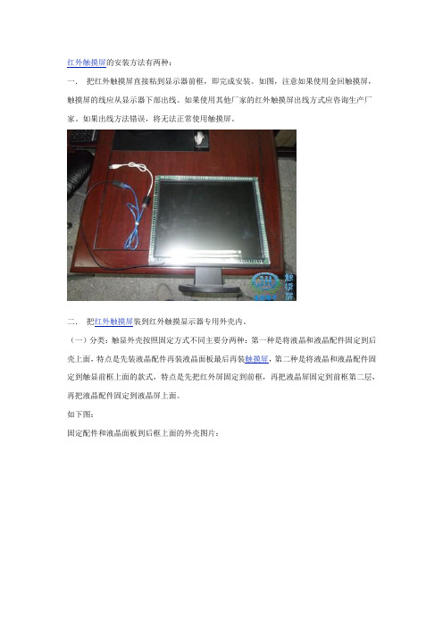
红外触摸屏的安装方法有两种:一.把红外触摸屏直接粘到显示器前框,即完成安装。
如图,注意如果使用金回触摸屏,触摸屏的线应从显示器下部出线。
如果使用其他厂家的红外触摸屏出线方式应咨询生产厂家。
如果出线方法错误,将无法正常使用触摸屏。
二.把红外触摸屏装到红外触摸显示器专用外壳内。
(一)分类:触显外壳按照固定方式不同主要分两种:第一种是将液晶和液晶配件固定到后壳上面,特点是先装液晶配件再装液晶面板最后再装触摸屏,第二种是将液晶和液晶配件固定到触显前框上面的款式,特点是先把红外屏固定到前框,再把液晶屏固定到前框第二层,再把液晶配件固定到液晶屏上面。
如下图:固定配件和液晶面板到后框上面的外壳图片:固定液晶面板和配件到前框上的款式图片:(二)内部构造:红外触摸屏显示器内部结构主要由液晶配件,液晶面板,红外触摸屏,组成:1.液晶配件(在广州的石牌西金桥市场二楼可以买到所有的配件)如下图:(此图为把液晶配件和液晶面板固定到后框上面的A左黄色小板为高压条,高压条通过连接线从液晶驱动板上面取电,将12V的电转化为高压电,然后供给液晶面板的灯管,使液晶面板灯管发光。
市面上比较流行可靠的品牌有:中联,中正友,乐华,质量都较稳定。
B.右绿色小板为液晶驱动板,作用是起到液晶面板的驱动作用,是液晶面板与电脑之间的显示信号转化的中转站,市面上比较流行的稳定的品牌有:乐华,顶科,凯旋。
C.上部五个键的小板为液晶按键开关。
与液晶驱动板进行连接,通过按键来对液晶进行调节,同普通显示器的按键功能是一样的。
注意:按键板规格尺寸不一,在购买红外触摸屏显示器外壳的时候,应该要求外壳厂家配送,否则市场上几乎找不到匹配的按键开关。
D.线材:a.高压条线(连接液晶驱动板与高压条的作用,注意应当使用高压条配送的配套的线,否则有可能出现高压条与连接线插口不匹配。
如下图:b.VGA线(连接电脑与液晶驱动板之前的线,按照拼口的正反方向插上即可,如果反了,就插不到位,容易判断。
触摸屏安装说明
触摸屏软件安装说明
1.驱动程式安装步骤。
(USB连接法)(串口连接法)
将触摸连接线正确连接到计算机主机上(如上图),随机驱动光盘放在CD/DVD光驱上,双
击打开桌面上我的电脑图标,然后打开触摸屏驱动文件夹,根据计算机的系统,选择正确的驱动文件夹
如计算机是Windows XP,则选择文件夹,如图,打开文件夹,选择双击打开
安装程序文件进行安装,安装过程中均为系统默认选项,每步点击
Next(下一步)系统进行安装。
(如下图)
安装完成,触摸屏已可正常工作。
2.触摸屏校正
驱动安装完成,如果触摸屏定位不准。
打开电脑桌面控制程序,进入控制程序,
如图选择工具标签,
选择线性设置,进入线性设置程序(白屏,边角并出现闪烁),如图。
PTN设备安装规范掌中宝

PTN设备安装规范“掌中宝”1、安全警告1. 电压警告:遵守当地用电规范,操作时严禁佩戴手表、戒指等易导电物品。
机柜有水,请关闭电源;上电前确保没有人员与电源接触。
2. 钻孔警告:在机柜上钻孔,必须佩戴绝缘手套。
注意防止飞溅的金属进入眼睛,防止金属屑进入机柜。
钻孔后及时打扫机柜。
3. 雷击警告:为避免雷击损伤设备,应及时做好设备的接地工作。
在出现雷电时,应避免人员与设备有任何的接触。
4. 静电警告:进行设备操作(即存储、安装、拆封等)或插拔单板时,应佩戴防静电手环。
进行插拔单板操作时,切勿用手接触单板上器件、布线或连接器引脚。
5. 腐蚀警告:一旦出现电池电解液外漏,应尽快将漏液电池搬离机房。
在处理具有腐蚀性物品时,要佩戴防腐蚀手套,并做好通风。
6. 激光警告:进行光纤的安装、维护等各种操作时,严禁肉眼靠近或直视光纤出口。
7. 搬运警告:搬运前检查设备是否有锐利的边缘。
搬抬时避免身体出现扭曲或弯曲,应将设备贴近身体。
8. 堆放警告:严禁在设备周围堆放具有易燃、易腐蚀性的物体。
安装后及时清理机房。
2、硬件安装2.1硬件安装流程硬件安装流程图:2.2安装方式ZXCTN 6100支持三种安装方式:台式安装、壁挂式安装和内置机柜安装。
安装ZXCTN 6100时,应根据现场实际情况和用户要求确定设备的具体安装方式。
ZXCTN 6200、6300、9000系列只支持内置机柜安装。
台式安装:图1:台式安装壁挂式安装:图2壁挂式安装机柜式安装:1、首先需要安装设备固定在机柜上的侧耳,安装如下:(下面为设备的双侧平面图)122、安装走线卡,将走线卡紧靠在子架右两侧的安装位置上。
采用M3*8螺钉,将走线卡紧密固定在子架上,如下图所示:13、安装设备入机柜方法:1. 将一个与子架等高或稍高一点的木尺或木条放在子架法兰(挂耳)后,与子架底部对齐,用铅笔通过法兰安装孔在木尺上好记号。
2. 把有记号木尺的底端搭在机柜的托轨上。
- 1、下载文档前请自行甄别文档内容的完整性,平台不提供额外的编辑、内容补充、找答案等附加服务。
- 2、"仅部分预览"的文档,不可在线预览部分如存在完整性等问题,可反馈申请退款(可完整预览的文档不适用该条件!)。
- 3、如文档侵犯您的权益,请联系客服反馈,我们会尽快为您处理(人工客服工作时间:9:00-18:30)。
MSAR1OCEO V1.0 09.01.2009
Installation guide /
PT-Series
1
3
MSAR1OCEO V1.0
Product View /
PT070
Outlet /
Model A B C H L PT057PT070
156.5mm/6.16"124mm/4.88"39mm/1.53"136mm/5.35"168.5mm/6.63"175mm/6.88"
132.5mm/5.21"
29mm/1.14"
143.3mm/5.64"
188mm/7.4"
Cutout /
PT057
1 Power connector (terminal) / (terminal)
2 Com2 6-pin (terminal) / com2 6-pin( )
3 USB connector / USB
4 Ethernet port /
5 Com1 9-pin female / Com1 9-pin
6 USB client / USB
7 Micro SD slot / Micro SD 8 LED Power Light /
Parts Introduction /
2
1
3
46
57
2
146
57
3Panel fixing /
Fixing Screw /
8
8
5
MSAR1OCEO V1.0
Connections /
Com 1 (DB-9 Female) / DB-9
Pin Description
1RD-422 TXD+ / RS-485+
2RS-232 RXD 3RS-232 TXD 4RS-422 RXD+
5GND
6RS-422 TXD- / RS-485-7RS-232 RTS 8RS-232 CTS 9
RS-422 RXD-7
MSAR1OCEO V1.0
Download Cable /
Dispose of battery /
Battery /
Battery /
MATSUSHITA/PANASONIC 3V 50mAh Vanadium Lithium Rechargeable Battery type VL2330/1HF
The products have been designed for use in an industrial environment in compliance with the 2004/108/CE directive.
The products have been designed in compliance with:
EN 61000-6-4 EN 55011 Class A EN 61000-6-2
EN 61000-4-2EN 61000-4-3EN 61000-4-4EN 61000-4-5EN 61000-4-6EN 61000-4-8EN 61000-4-11
The installation of these devices into the residential, commercial and light-industrial environments is allowed only in the case that special measures are taken in order to get the conformity to IEC-61000-6-3.
Reproduction of the contents of this copyrighted document, in whole or part, without written permission of Cermate Technologies Inc., is prohibited. .
Copyright © 2009 Cermate Technologies Inc.
7F-1, No.168, Lien Cheng Rd., Chung-Ho City, Taipei County, Taiwan
A-Type / 機型-A
Com 1 (DB-9 Female) / DB-9
Pin Description
1RD-422 TXD+ / RS-485+
2RS-232 RXD 3RS-232 TXD 4RS-422 RXD+
5GND
6RS-422 TXD- / RS-485-7RS-232 RTS 8RS-232 CTS 9
RS-422 RXD-B-Type / 機型-B
Com 1 (DB-9 Female) / DB-9
Pin Description
1RD-422 TXD+ / RS-485+
2RS-232 RXD 3RS-232 TXD 4RS-422 RXD+
5GND
6RS-422 TXD- / RS-485-7RS-232 RTS 8RS-232 CTS 9
RS-422 RXD
C-Type / 機型-C
Power supply /
Powered by a Low Voltage / Limited Energy power source
Do not open the rear cover of the panel when power is applied
Ensure that the power supply has enough power capacity for the operation of the equipment
Com1 Connector (Com1 )9Pin Male (9Pin )
PC Connector (PC )9Pin Female (9Pin )RXD 2 TXD 3
SG 5
3 TXD 2 RXD
5 SG
Com1
Com2 Connector (Com2 )
Terminal Block 6Pin (6Pin )
PC Connector (PC )9Pin Female (9Pin )RXD 5 TXD 4
SG 6
3 TXD 2 RXD
5 SG
B-Type Com2Com2 Connector (Com2 )
Terminal Block 6Pin (6Pin )
PC Connector (PC )9Pin Female (9Pin )RXD 5 TXD 4
SG 6
3 TXD 2 RXD
5 SG
C-Type Com2Com2(6 pins)
Com2(6 pins)
Com2(6 pins)。
