TC554001FTI-10V中文资料
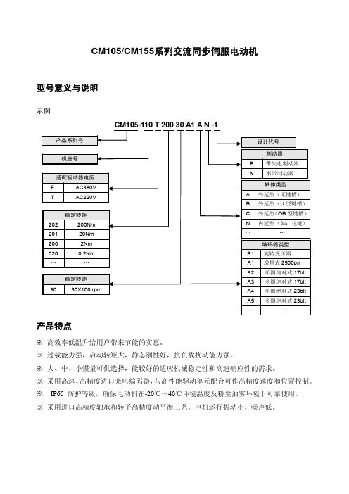
四方CM105、CM155伺服电机说明书
27 67 1500 6.1×10⁻³ 103 1.69 0.28
35 70 1000 8.6×10⁻³ 134 2.2 0.31
35 70 1500 8.6×10⁻³ 90 1.45 0.14
48 96 1500 9.5×10⁻³ 94 1.5 0.11
线电感 mh
2.42
1.93
1.74
3.28
5.37
5.37
5.37
2.2
驱动器输入电压(V)
AC220
编码器线数(P/R)
增量式 2500/绝对式 17bit 或 23bit
极对数
4
绝缘等级
F
防护等级
IP65
130电机(380V)技术参数
电机型号
额定输出功率 (k·W)
CM105/155-13 CM105/155-13 CM105/155-13 CM105/155-13 CM105/155-13
轴伸类型
A 外延型(无键槽)
B 外延型(U 型键槽)
C 外延型(OB 型键槽)
N 内延型(如:花键)
…
…
编码器类型
R1 旋转变压器
A1 增量式 2500p/r
A2 单圈绝对式 17bit
A3 多圈绝对式 17bit
A4 单圈绝对式 23bit
A5 多圈绝对式 23bit
…
…
※ 高效率低温升给用户带来节能的实惠。 ※ 过载能力强,启动转矩大,静态刚性好,抗负载扰动能力强。 ※ 大、中、小惯量可供选择,能较好的适应机械稳定性和高速响应性的需求。 ※ 采用高速、高精度进口光电编码器,与高性能驱动单元配合可作高精度速度和位置控制。 ※ IP65 防护等级,确保电动机在-20℃~40℃环境温度及粉尘油雾环境下可靠使用。 ※ 采用进口高精度轴承和转子高精度动平衡工艺,电机运行振动小、噪声低。
PAP-10V-S中文资料

Features ––––––––––––––––––––––––• Secure locking deviceThe housing has a locking device to prevent accidentaldisconnection because of routing of wires or of vibration, and also reverse and different circuit numbers mating.• Interchangeable between crimp and IDC socketBoth crimp and IDC sockets use the same headers and wire-to-wire mating halves.• Secondary retainersSecondary retainers enhance safety in case of partial insertion or accidental release of the contact.• Harness variationPAL, wire-to-wire crimp style connector, increases wire harness variation.PA connector(Standard type, Retainer mountable type)• Highly reliable contactThe box contact supplies stable contact performance even under conditions of vibration, distortion, low voltage or low current.• Insertion guide mechanismHeader has housing insertion guides for easy and secure insertion.• Flanged press pinTop entry type header has flanged press pins, preventing accidental removal of the pins that might result from thedistorted unmating especially in the case of small No. of circuits.PAF connector• The industry’s first secure lock IDC connectorsBy separating ID section and secure lock section, the industry ’s first secure lock specification has been achieved for IDC that was said to be impossible. Our fully automatic IDC machines, BCD-M5BP (for simple harness) and CAM-M12B, SAD-M12E (for multi-harness), can be applied for harness making.• Metallic strain reliefMetallic strain relief on the contact securely grips wire insulation that can avoid direct stress of vibration or impact. The same grip strength as insulation barrel of crimp style contact could be achieved.• Retainer with four locking pointsThe new four locking points design ensures wire retention force of every direction that is almost superior to contact retention force of crimp style connectors. It also completely covers exposed terminated ID contact.PAL connector• The industry’s first wire to wire 2.0mm (.079")pitch retainer mountable type connector.• Either with or without panel lock can be selected according to application.*Contact JST if Lead-Free product is required.*Refer to "General Instruction and Notice when using Terminals and Connectors" at the end of this catalog.* Contact JST for details.Standards ––––––––––––––––––––––Recognized E60389Certified LR20812PA FAMILY SERIES/PA•PAF•PAL CONNECTORWire-to-board (Crimp style/IDC) / Wire-to-wire (Crimp style/IDC)PA FAMILY SERIES /PA•PAF•PAL CONNECTORList of combinations ––––––––––––––––––––––––––––––––––––––––––––––––––––––PA Connector (Standard type)• Current rating:3A AC, DC(AWG#22)• Voltage rating:250V AC, DC• Temperature range:-25˚C to +85˚C(including temperature rise in applying electrical current)• Contact resistance:Initial value/10m Ωmax.After environmental testing/20m Ωmax. • Insulation resistance:1,000M Ωmin.• Withstanding voltage:800V AC/minute• Applicable wire:AWG #28 to #22• Applicable PC board thickness: 1.6mm(.063")PA Connector (Retainer mountable type)• Current rating:3A AC, DC(AWG#22)• Voltage rating:100V AC, DC• Temperature range:-25˚C to +85˚C(including temperature rise in applying electrical current)• Contact resistance:Initial value/15m Ωmax.After environmental testing/25m Ωmax. • Insulation resistance:1,000M Ωmin.• Withstanding voltage:800V AC/minute• Applicable wire:AWG #28 to #22PAF Connector• Current rating: 1.0A AC, DC(AWG#26)• Voltage rating:100V AC, DC• Temperature range:-25˚C to +85˚C(including temperature rise in applying electrical current)• Contact resistance:Initial value/15m Ωmax.After environmental testing/25m Ωmax. • Insulation resistance:1,000M Ωmin.• Withstanding voltage:800V AC/minute• Applicable wire:UL1061(Contact JST for details regarding other UL wires.)AWG #26Conductor/7 strands, tin-coated annealed copperInsulation O.D./0.9 to 1.0mm(.035" to .039") PAL Connector• Current rating:3A AC, DC(AWG#22)• Voltage rating:100V AC, DC• Temperature range:-25˚C to +85˚C(including temperature rise in applying electrical current)• Contact resistance:Initial value/15m Ωmax.After environmental testing/25m Ωmax. • Insulation resistance:1,000M Ωmin.• Withstanding voltage:800V AC/minute• Applicable wire:AWG #28 to #22PA FAMILY SERIES /PA CONNECTOR (Crimp style Standard type)Contact –––––––––––––––––––––––––––––––––––––––––––––––––––––––––––––––––Housing –––––––––––––––––––––––––––––––––––––––––––––––––––––––––––––––––For availability, delivery and minimum order quantity, contact JST.ex.PAP-02V-S -S…natural (white)K…black R…red E…blue M…green O…orange N…brownP…purple PK…pink Y…yellow L…lemon yellow FY…vivid yellow LE…light blue H…gray TR…tomato redPA FAMILY SERIES /PA CONNECTOR (Crimp style Retainer mountable type)Housing –––––––––––––––––––––––––––––––––––––––––––––––––––––––––––––––––R…red E…blue Y…yellow M…greenRetainer –––––––––––––––––––––––––––––––––––––––––––––––––––––––––––––––––PA FAMILY SERIES /PA CONNECTOR (Crimp style Retainer mountable type)Retainer –––––––––––––––––––––––––––––––––––––––––––––––––––––––––––––––––PA FAMILY SERIES /PAF CONNECTOR (Insulation displacement type)R…red E…blue M…green Y…yellowPA FAMILY SERIES /PAL CONNECTOR (Wire-to-wire type)Housing –––––––––––––––––––––––––––––––––––––––––––––––––––––––––––––––––Retainer –––––––––––––––––––––––––––––––––––––––––––––––––––––––––––––––––Retainers are interchangeable with those of the PA crimp style retainer mountable type.For availability, delivery and minimum order quantity, contact JST.ex.PALR-02V(F)-oo-(blank)…natural (white)R…red E…blue M…green Y…yellowContact –––––––––––––––––––––––––––––––––––––––––––––––––––––––––––––––––。
施耐德宝光微机保护产品选型手册说明书
Schneider Baoguang关于施耐德宝光施耐德(陕西)宝光电器有限公司(简称SSBEA或施耐德宝光)是施耐德电气有限公司与陕西宝光集团有限公司共同组建的一家专业从事中、系统及相关产品研发、生产和销售的中外合资企业。
高新科技园区。
在世界五百强企业与中国中压电器龙头企业的通力合作下,作为国内中压行业著名的“宝光”品牌真空断路器的唯一合法生产商,施耐德宝光秉承精益生产科学理念,凭借品质过硬、安全可靠的全系列高品质产品和覆盖用户全生命周期的完善服务,帮助用户实现卓越的生产运营绩效和市场竞争力,用品质的“不妥协”实现可持续发展之道。
我们致力于将施耐德宝光打造成为中国卓越和高效的中压断路器和系统的制造平台,依托自身的专业优势,为广大用户和合作伙伴提供领先的总成本和长期全面的安心保障。
目录V5系列新一代微机保护测控装置 (1)产品概述 (1)产品特点 (2)型号及功能说明 (3)保护功能 (4)测控功能 (6)技术参数 (7)典型接线图 (8)外形尺寸及面板开孔尺寸 (11)V5订货选型表 (12)V3系列微机保护测控装置 (13)产品概述 (13)产品特点 (14)型号及功能说明 (15)保护功能 (16)测控功能 (17)技术参数 (18)典型接线图 (19)外形尺寸及面板开孔尺寸 (21)V3订货选型表 (22)V3U微机综合保护装置 (23)产品概述 (23)型号及功能说明 (24)保护功能 (25)测控功能 (26)技术参数 (27)外形尺寸图/典型接线图 (28)后台系统 (29)系统总体结构 (30)V5系列新一代微机保护测控装置是一种用于测量、控制、保护、通讯一体化的智能设备,产品主要用于工业及能源领域对线路、变压器、电动机及电容器的保护测控。
此产品外观时尚、结构精巧、大屏幕液晶显示,图形化中文菜单,四位方向导航盘,操作快捷方便。
内部基于SOC芯片软件方案,32位处理器,并根据硬件进行深度改良优化的嵌入式操作系统,使CPU运行效率更高。
电压互感器测试仪说明书
电压互感器测试仪说明书由于输入输出端子、测试柱等均有可能带电压,在插拔测试线、电源插座时,会产生电火花,小心电击,避免触电危险,注意人身安全!安全要求请阅读下列安全注意事项,以免人身伤害,为了避免可能发生的危险,只可在规定的范围内使用。
只有合格的技术人员才可执行维修。
—防止火灾或人身伤害使用适当的电源线。
只可使用专用并且符合规格的电源线。
正确地连接和断开。
当测试导线与带电端子连接时,请勿随意连接或断开测试导线。
注意所有终端的额定值。
为了防止火灾或电击危险,请注意所有额定值和标记。
在进行连接之前,请阅读使用说明书,以便进一步了解有关额定值的信息。
使用适当的保险丝。
只可使用符合规定类型和额定值的保险丝。
避免接触裸露电路和带电金属。
有电时,请勿触摸裸露的接点和部位。
请勿在潮湿环境下操作。
请勿在易爆环境中操作。
-安全术语警告:警告字句指出可能造成人身伤亡的状况或做法。
目录一、概述 (5)二、主要技术指标 (5)三、使用环境条件 (6)四、测量原理 (6)五、使用方法1、面板配置 (7)2、操作键盘 (7)3、开机 (8)4、仪器复位 (8)5、误差测试 (8)6、电网频率测试 (14)一、概述HGQY-H便携式低校高式电压互感器测试仪是最适合于在现场对电压互感器进行误差测试的全自动智能仪器。
用户不再需要配置笨重的升压器,标准电压互感器,负载箱及调压器(或自动检测台),单台仪器就能对10kV、10kV/3、35kV、35kV/3、110kV/3、220kV/3的电压互感器进行快速测量。
全过程(包括额定、下限的所有测量点)的测试时间不超过1分钟(不含接线时间),其准确度达到0.05级。
本仪器采用320×240点阵的大屏幕液晶显示器,各点的误差可以在同一屏上显示,所有操作均可点击屏幕菜单轻松完成。
本仪器可以存贮200组数据,备有专用接口与PC机通讯。
本仪器约重15kg。
二、主要技术指标●测试范围:10kV、10kV/3、35kV、35kV/3、110kV/3、220kV/3●二次负荷:2.5VA~600VA cosФ=0.8●测量精度:0.05级●测频率:准确度为0.01Hz●仪器设有实时时钟,可实时记录测试时间。
ABB低压直流控制产品断路器接触器隔离开关等

3极
4极
S800 PV-S IEC60947-2
1500
8
600 - 800 (2极) 100 (3极)
3极
1200 (4极)
4极
S800 PV-M IEC60947-3
1500
8
800 (2极)
32 / 64 / 125 Icw=1.5
2极
1200 (3极)
典型应用行业
直流产品被广泛地应用在光伏发电、电力牵引、关键电源以及港口等低压领域。ABB 全系列的直流断路器、隔离开关和熔断器以及监测和控制产品,凭借其优越的性能, 为直流配电系统提供高品质的保证。
光伏设备
随着太阳能行业的迅猛发展,大型装机容量的太阳能发电厂不断增加,大型光伏电厂 对所需的控制和保护设备的性能要求也越来越高。 当光伏电厂的功率超过某一水平时,需要采用断路器或隔离开关。特别是逆变器的保 护隔离,对低压元器件提出了更高的要求。 ABB Emax DC 直流专用空气断路器、Tmax塑壳断路器及其隔离开关系列,其优越的 性能得到全球逆变器制造商的认可,并作为他们配电的首要选择。 全新的1000V DC OT系列隔离开关是针对太阳能光伏系统中的直流分断问题而专门设 计的。在直流1000V DC时,该系列隔离开关具有出色的分断能力。 ABB 光伏专用系列产品还包括S800 PV系列,它又可分为高性能微型断路器S800 PV - S 和隔离开关S800PV-M两个系列,其额定电压最高可达1200VDC。考虑到光伏发电对 高直流电压的实际应用需求,S800PV系列产品以其高电压、防逆流、与极性无关的保 护特性和紧凑体积等特点,为客户提供了完美的光伏组件和直流汇流解决方案。
额定电流 (A)
额定短时耐受短路电流 lcw (kA)
ICS系列电子皮带秤说明书
百度文库- 让每个人平等地提升自我- 1 -ISC系列电子皮带秤使用说明书本手册属北京奥特曼克公司所有,未经奥特曼克公司书面许可,任何单位和个人不得翻印或散布,违者必究!北京奥特曼克技术有限公司地址:北京市丰台区科技园邮编:100070电话:010—传真:0京制********号目录百度文库- 让每个人平等地提升自我第一章绪言 (5)1.1 概述 (5)1.2 主要技术指标 (5)1. 3系统组成和工作原理 (6)1.4 开箱和检验 (6)第二章皮带秤的安装准则 (7)2.1 总述 (7)2.2 风和气候的影响 (7)2.3 输送机支架 (7)2.4 秤的安装位置 (7)2.5 重力式拉紧装置 (8)2.6皮带槽形变化 (8)2.7称重托辊 (8)第三章安装 (10)第I部分ICS-2 0的安装 (10)A3.1 概述 (10)A3.2 术语 (10)A3.3 安装位置 (10)A3.4 安装准备 (10)A3.5 称重桥架的安装 (11)第II部分ICS-17的安装B3.1 概述 (12)B3.2 术语 (12)B3.3 安装位置 (12)B3.4 安装准备 (12)B3.5 称重桥架的安装 (13)B3.6 秤的托辊安装 (13)第III部分称重仪表的安装C3.1 位置 (14)C3.2 安装 (14)C3.3 安全警示 (15)C3.4 接线 (15)第IV部分速度传感器的安装D3.1 概述 (18)D3.2 机械安装 (18)第四章系统校准 (19)- 2 -百度文库- 让每个人平等地提升自我- 3 - 4.1 概述 (19)4.2 精度 (19)4. 3 20/17型皮带秤系统简述 (19)4.4 仪表初始设置 (21)第五章操作明细 (30)5.1 菜单显示 (30)5.2运行显示 (31)5. 3 主菜单1 (32)5.3.1 读取当前零点及手动调零点 (32)5.3.2自动零点校准 (33)5.3.3 读取间隔及手动校准间隔 (33)5.3.4 自动调间隔 (33)5.3.5实物校准间隔 (33)5.4主菜单2 (35)5.4.1显示 (35)5.4.2选择累计单位 (35)5.4.3选择流量单位 (35)5.4.4设定显示流量缓冲时间 (36)5.4.5第三行显示 (36)5.4.6秤数据 (36)5.4.7设置最大秤容量 (36)5.4.8选择秤分度 (36)5.4.9皮带秤型号 (37)5.2.10设置零点死区 (37)5.4.11远程累计输出分度 (37)5.4.12累计脉冲宽度 (37)5.4.13称重传感器容量 (37)5.4.14称重传感器灵敏度 (37)5.2.15称重传感器数量 (37)5.4.16定义速度信号输入方式 (37)5.4.17称重传感器阻值 (37)5.4.18托辊间距 (37)5.4.19最大kg/m (37)5.4.20皮带倾角 (37)5.4.21校准数据 (37)5.4.22自动零点跟踪 (37)5.5 主菜单3 (37)5.5.1诊断 (38)5.5.2保护设定 (38)百度文库- 让每个人平等地提升自我- 4 -5.5.3更改密码 (38)5.6 主菜单4 (38)5.6.1输入设定 (38)5.6.2输出设定 (39)5.6.3报警设定 (39)5.6.4高流量设定点 (40)5.6.5高流量报警延时 (40)5.6.6低流量报警点 (40)5.6.7低流量报警延时 (40)5.6.8控制偏差设定点 (41)5.6.9控制偏差报警延时 (41)5.6.10报警定义 (41)5.6.11报警复位选择 (41)主菜单5 (42)5.7.1波特率设定 (22)5.7.2 地址设定 (22)5.7.3功能选择 (22)第六章维护 (43)6.1日常维护 (43)6.2故障排除 (43)附1.通讯板配置 (45)附2.电流板 (46)附2.参数设定记录 (47)百度文库- 让每个人平等地提升自我- 5 - 第一章绪言1.1概述奥特曼克ICS-20,ICS-17,ICS-14型电子皮带称,是在皮带输送系统进行连续计量的理想设备,具有结构简单、称量准确,使用稳定、操作方便、维护量少等优点,不仅适用于常规环境,而且使用于酸、碱、盐及大气副食环境。
IVCR1401应用手册说明书

IVCR1401 应用手册AN-0001IVCR1401 是一款高速4A拉、灌电流的SiC MOSFET 和IGBT驱动芯片。
它是工业界首款采用8引脚封装,包括负压生成,退饱和以及UVLO设置的SiC MOSFET和IGBT驱动器。
它专为低侧驱动而设计,但在自举电路或隔离偏置中应用,也非常适合于高侧驱动。
为了减少过电流响应时间并提高SiC MOSFET应用的抗噪声能力,与IGBT驱动器相比该驱动器的设计得到了增强。
退饱和电流源增加到1mA,因此可以使用更大的消隐电容来减少寄生和噪声的影响。
大多数SiC MOSFET都没有反并联二极管,这会导致较高的V SD(体二极管正向电压)压降,使在自举电路中难以得到应用。
本文档将详细介绍使用IVCR1401的SiC MOSFET栅极驱动解决方案。
目录1 PCB布局建议 (1)2 Vcc 选择和 UVLO 设置 (2)3 负压建立和电容选择 (3)4 退饱和过电流保护设置 (4)4.1 过电流和短路保护设置 (4)4.2 dv/dt 在短路关断延时的影响 (5)5 自举电路中的高侧驱动应用 (8)6 隔离偏置中的高侧驱动应用 (9)1 PCB布局建议良好的PCB布局是实现所需电路性能的关键步骤。
首要的任务是地的确立。
建议将热焊盘与驱动器地相连。
一般规则是,对于位置布置,电容比电阻具有更高的优先级。
一个1uF和一个0.1uF的去耦电容应靠近VCC引脚,并接地至驱动器电路的地。
负压电容应靠近OUT和NEG 引脚放置。
为了减小负压纹波,应使用超过100倍Cg电容的X7R电容。
消隐电容也应靠近驱动器的DESAT引脚,并且该电容应由C0G或等效材料制成。
如果输入信号走线必须通过一些噪声区域,则IN的输入端可能需要一个小的滤波器(时间常数为10ns)。
在/FAULT引脚的输出上建议加一个滤波电容,来减小高频噪声产生的干扰,该滤波电容的选取需要考虑/FAULT和5VREF之间连接的电阻Rft的值,若Rft为1.3kΩ或6kΩ或20kΩ,则对应建议使用的滤波电容分别为1nF或200pF或56pF。
艾普斯电源

交流电源供应器ACST-N 系列产品手册艾普斯电源有限公司为客户提供全方位的技术支持,用户可与就近的艾普斯电源有限公司办事处或客户服务中心联系,也可直接与公司总部联系。
艾普斯电源有限公司版权所有,保留一切权利。
内容如有改动,恕不另行通知。
艾普斯电源有限公司地址:苏州新区科技工业园火炬路39号安全须知1.电源内部有高压,非本公司或本公司授权的技术人员,请勿擅自打开机箱盖,否则会有触电的危险。
2.当模拟电网电源需要移动或重新配线时,必须切断输入,并保证模拟电网电源断电停机10分钟以上,否则电源内部电容仍可能有电,有触电的危险。
3.为确保用户的人身安全,本系列电源产品必须有良好的接地保护,在使用之前首先要可靠接地。
4.使用环境及保存方法对本产品的使用寿命及可靠性有一定影响,因此,请注意避免长期在下列工作环境中使用:z超出技术指标规定(温度-20℃~40℃,相对湿度5%~95%)的高、低温和潮湿场所;z阳光直射或靠近热源的场所;z有振动、易受撞的场所;z有粉尘、腐蚀性物质、盐份和可燃性气体的场所。
5.请保持进、排气孔的通畅。
进、排气孔的通风不畅会导致模拟电网电源内部的温度升高,使机器中元器件的寿命缩短,从而影响整机寿命。
6.液体或其它外来物体绝对不允许进入电源机箱内。
7.万一周围起火,请使用干粉灭火器,若使用液体灭火器会有触电危险。
8.如果长时间放置不使用,必须将模拟电网电源存放在干燥的环境中,标准机的存贮温度范围:-40℃~+70℃。
目 录第一章 产品介绍 (1)1.1ACST系列模拟电网电源特点 (1)第二章 ACST系列模拟电网电源工作原理及结构 (2)2.1ACST系列模拟电网电源工作原理 (2)2.2系统功能框图 (2)2.3产品规格 (3)2.4外形结构 (4)第三章 设备的安装 (10)3.1开箱检验 (10)3.2安装程序 (10)3.2.1 安装注意事项 (10)3.2.2 模拟电网电源的安装步骤 (11)第四章 操作 (13)4.1面板及按键功能介绍 (13)4.2LCD界面说明 (15)4.3ACST系列模拟电网电源的运行模式 (30)4.3.1 通用模式 (30)4.3.2 步阶模式 (30)4.3.3 渐变模式 (31)4.3.4 远控模式 (31)4.4ACST系列模拟电网电源的常见操作 (31)4.4.1 通用模式操作 (31)4.4.2 步阶模式操作 (36)4.4.3 渐变模式操作 (38)4.4.4 系统参数设置 (39)4.4.5 复用键 (41)第五章 RS232/RS485通讯 (43)5.1RS232/RS485通讯接线 (43)5.2相关指令使用说明 (44)5.3协议约定说明 (44)第六章 维护保养 (46)6.1维护保养注意事项 (46)6.2风扇 (46)6.3系统目检 (46)6.4季保养 (47)6.5年保养 (48)第七章 异常处理 (49)第八章 售后服务 (51)第一章产品介绍 1第一章 产品介绍1.1 ACST系列模拟电网电源特点ACST系列电源是我公司的新一代模拟电网可编程电源,不仅能提供连续、纯净、稳定之正弦电压,并可透过内部控制模块通讯模块,实现用户PC机对多台联机电源系统的本地控制和远程控制,同时内部电子电路可快速侦测过电流、过载、过压和输出短路并自动保护切断输出发出告警。
FZT953 100V PNP中间电平转换器SOT223型号产品数据手册说明书

100V PNP MEDIUM POWER TRANSISTOR IN SOT223Features∙BV CEO > -100V∙ I C = -5A High Continuous Collector Current ∙ I CM = -10A Peak Pulse Current∙ Low Saturation Voltage V CE(SAT) < -115mV @ -1A ∙ R CE(SAT) = 75m Ω for a Low Equivalent On-Resistance ∙ h FE Specified up to -10A for a High Gain Hold-Up ∙ Complementary NPN Type: FZT853∙ Lead-Free Finish; RoHS Compliant (Notes 1 & 2)∙ Halogen and Antimony Free. “Green” Device (Note 3) ∙ Qualified to AEC-Q101 Standards for High Reliability ∙ PPAP Capable (Note 4)Mechanical Data∙ Case: SOT223∙ Case Material: Molded Plastic. “Green” M olding Compound. UL Flammability Rating 94V-0∙ Moisture Sensitivity: Level 1 per J-STD-020∙∙Weight: 0.112 grams (Approximate)Notes: 1. EU Directive 2002/95/EC (RoHS) & 2011/65/EU (RoHS 2) compliant. All applicable RoHS exemptions applied.2. See https:///quality/lead-free/ for more information about Diodes Incorporated’s definitions of Halogen - and Antimony-free, "Green" and Lead-free.3. Halogen- and Antimony-free "Green” products are defined as those which contain <900ppm bromine, <900ppm chlorine (<1500ppm total Br + Cl ) and <1000ppm antimony compounds.4. Automotive products are AEC-Q101 qualified and are PPAP capable. Automotive, AEC-Q101 and standard products are electrically and thermally the same, except where specified. For more information, please refer to https:///quality/.5. For packaging details, go to our website at https:///design/support/packaging/diodes-packaging/.SOT223Top ViewDevice SymbolTop View Pin-OutGreenFZT 953 = Product Type Marking Code YWW = Date Code MarkingY or Y = Last Digit of Year (ex: 7 = 2017) WW or WW = Week Code (01–53)Y W WFZT 953Thermal Characteristics (@T A = +25°C, unless otherwise specified.)Notes: 6. For a device surface mounted on 52mm x 52mm x 1.6mm FR4 PCB with high coverage of single sided 2oz copper, in still air conditions; the device is measured when operating in a steady-state condition.7. Same as Note 6, except the device is surface mounted on 25mm x 25mm with 1oz copper.8. Thermal resistance from junction to solder-point (at the end of the collector lead).9. Refer to JEDEC specification JESD22-A114 and JESD22-A115.Thermal Characteristics and Derating Information100m11010010m 100m110Single Pulse. T amb =25°C 52mmX52mm single sided 2oz CuV CE(sat)Limit100µs1ms10ms100ms1sDCSafe Operating Area-I C C o l l e c t o r C u r r e n t (A )-V CE Collector-Emitter Voltage (V)Derating CurveTemperature (°C)M a x P o w e r D i s s i p a t i o n (W )Transient Thermal ImpedanceT h e r m a l R e s i s t a n c e (°C /W )Pulse Width (s)Pulse Power DissipationPulse Width (s)M a x P o w e r D i s s i p a t i o n (W )Electrical Characteristics(@T A = +25°C, unless otherwise specified.)Note: 10. Measured under pulsed conditions. Pulse width ≤300μs. Duty cycle ≤ 2%.Typical Electrical Characteristics (@T A = +25°C, unless otherwise specified.)Package Outline DimensionsPlease see /package-outlines.html for the latest version.SOT223Suggested Pad LayoutPlease see /package-outlines.html for the latest version.SOT223°°。
TC55说明书

TC5510/TC5522/TC5530/TC5522R/TC5530R运动进电控制器(步机控制器)说书明正视图 全 图左视图 后视图 右视图TC55-MOD 全图注:TC55系列产品,面板尺寸及外壳面膜完全一致,TC55-MOD 为选配产品一、述篇 (3)概二、接篇 (5)连三、操作篇 (7)1.动执自行 (11)1.1实际运行 (11)空行 (11)1.2运1.3单执步行 (12)1.4终止程序 (12)手操作 (13)2动手高速 (13)2.1动点操作 (14)2.2动2.3回程序零 (14)2.4回机械零 (14)3程序管理 (16)3.1编辑程序 (16)程序入 (18)3.2读程序除 (19)3.3删3.4程序保存 (20)4参数设置 (20)4.2系统自检 (23)4.3 IO设置 (26)4.4用户管理 (28)四、程篇 (30)编五、附篇 (52)录一、概述篇TC55面板型运动控制器(数控系统)采用高性能32位CPU,驱动装置采用细分步进电机或交流伺服电机,配备液晶显示器,全封闭触摸式操作键盘。
该系统具有可靠性高,精度高,噪音小,操作方便等特点。
本控制器可控制1-3个电机运动,可实现点位、直线插补、圆弧插补等操作。
具有循环、跳转及简易PLC等功能。
简单、清晰的参数带给您方便和快捷的操作。
输入/输出的设置功能可方便您的使用和维修,适用于各类的1-3轴运动装置。
产品特点开机画面可自行修改控制器或上位计算机双模式编程独立24V电源反接保护 IO光耦隔离输出短接保护手动正反转可同步外部开关控制简易PLC逻辑参数区密码可设定适用产品类型l数控钻床系统、数控车床系统、数控铣床系统、数控磨床系统l裁剪机控制系统、切割机控制系统、焊接控制系统、点胶机控制系统、送料控制系统l位移台、一维控制平台、二维控制平台、三维控制平台l螺纹机控制系统、锁螺丝机控制系统l喷涂生产线控制系统、装配生产线控制系统、记米器控制系统技术特点l自动执行:可实现实际运行、空运行、单段执行、终止程序、启动和暂停功能l手动操作:可实现手动高、低速、点动操作、回程序零、回机械零等操作。
TC100B数据手册V1.3中文手册发布
青岛鼎信通讯股份有限公司目录1概述 (1)2功能特点 (1)3原理框图 (1)4引脚定义 (2)4.1 芯片引脚图 (2)4.2 引脚说明 (2)5功能描述 (3)5.1供电电源 (3)5.2过流保护功能 (3)5.3接收发送控制 (3)5.4数据收发 (3)6电气参数 (4)6.1额定直流电气参数 (4)6.2交流电气指标 (5)6.3电气特性图 (5)6.4ESD特性 (6)7封装尺寸 (7)8参考电路 (8)8.1典型应用电路 (8)8.2关键器件选型 (8)1概述XY•CN-PDC总线是一种可供电、无极性、两线制通信机制,具有通讯设备容量大,通讯速率高,设计简单,布线方便,抗干扰能力强等特点。
采用《可供电分布式控制协议XY•CN-PDC》,可保证在252个设备组网情况下,任一设备事件上报时间小于100mS,多点设备同时上报逐一提取,不会产生网络冲突。
XY•CN-PDC总线特别适用于三表集抄、智能家居控制、消防报警及联动控制、楼宇自动化控制等系统。
XY•CN-PDC总线采用主从方式通讯,TC100B芯片实现主站的通讯接口功能,TC001B芯片实现从站的通讯接口功能。
2功能特点静态功耗典型值小于1mA;工作电压范围宽:12V~36V;自带内部稳压输出:+5V,10mA;下行发码满幅电压调制,上行收码电流环解调,抗干扰能力强;最多可挂接252个节点设备;通讯距离1200m,上行通讯速率可达19200bps,下行通讯速率可达9600bps;采用半双工通讯;小体积QFN-16封装;可隔离设计保证电磁兼容特性;功率器件外置,芯片不易损坏;工作温度:-40℃~ +85℃。
3原理框图图1 TC100B原理框图4 引脚定义4.1 芯片引脚图T X DI D E TV O U TTREORXDBUSL GNDV D DV D E T REVINVBBUSHVCCN CR B图2 TC100B 芯片引脚图4.2注:当输入+5V/+3.3V 时,RXD 和EO 输出的高电平为+5V/+3.3V ,低电平为0V 。
施耐德压力传感器

用于控制气体、水、液压油、腐蚀性流体
● Nautilus® 电子压力传感器概述.......................................................................................................................... 10 ● Nautilus® XMLG优化型,无显示,量程从-1 bar ... 400 bar ○ 介绍 ............................................................................................................................................................................ 14 ○ 特性 ............................................................................................................................................................................ 15 ○ 压力传感器4...20 mA或0...10 V输出,型号,特性 ...................................................................................... 16 ○ 压力和真空开关,固态输出PNP或NPN,型号,特性...............................................................................22 ○ 压力传感器附件型号.............................................................................................................................................26 ○ XMLG压力传感器尺寸,接线图 ........................................................................................................................27 ● Nautilus® XMLK优化型,无显示,量程从0 bar ... 25 bar ○ 介绍 ............................................................................................................................................................................28 ○ 特性 ............................................................................................................................................................................29 ○ 压力传感器4...20 mA或0...10 V输出,型号,特性 ..................................................................................... 30 ○ 压力传感器附件型号,接线图...........................................................................................................................32 ○ XMLK压力传感器尺寸 ..........................................................................................................................................33 ● Nautilus® XMLE通用型,无显示,量程从-1 bar ... 600 bar ○ 介绍 ............................................................................................................................................................................34 ○ 特性 ............................................................................................................................................................................35 ○ 压力传感器4...20 mA输出,型号,特性 ........................................................................................................36 ○ 压力和真空开关,固态或继电器输出,型号,特性................................................................................. 40 ○ 压力传感器附件型号............................................................................................................................................ 44 ○ XMLE压力传感器尺寸,接线图 ........................................................................................................................45 ● Nautilus® XMLF通用型,带显示,量程从-1 bar ... 600 bar ○ 介绍 ........................................................................................................................................................................... 46 ○ 特性 ............................................................................................................................................................................47 ○ 压力传感器及压力和真空开关,型号,特性 .............................................................................................. 48 ○ 压力传感器及压力和真空开关,附件型号....................................................................................................72 ○ XMLF压力传感器尺寸,接线图.........................................................................................................................75
低较高式电压互感器现场测试仪使用说明书

低较高式电压互感器现场测试仪使用说明书武汉汉测电气有限公司Wuhan Hance Electric Co.,Ltd尊敬的顾客感谢您购买本公司低较高式电压互感器现场测试仪,在您初次使用该产品前,请您详细地阅读本使用说明书,将可帮助您熟练地使用本装置。
我们的宗旨是不断地改进和完善公司的产品,因此您所使用的产品可能与使用说明书有少许的差别。
如果有改动的话,我们会用附页方式告知,敬请谅解!您有不清楚之处,请与公司售后服务部联络,我们定会满足您的要求。
注意事项请阅读下列安全注意事项,以免人身伤害,并防止本产品或与其相连接的任何其它产品受到损坏。
为了避免可能发生的危险,本产品只可在规定的范围内使用。
只有合格的技术人员才可执行维修。
请勿擅自打开仪器,否则将不能得到包修等到各种服务,出现任何问题请先电话联系售后服务部。
由于输入输出端子、测试柱等均有可能带电压,您在插拔测试线、电源插座时,会产生电火花,小心电击,避免触电危险,注意人身安全!1◆防止火灾和人身伤害◆使用适当的电源线:只可使用本产品专用、并且符合本产品规格的电源线。
◆正确地链接和断开:当测试导线与带电端子连接时,请勿随意连接或断开测试线。
◆产品接地:本产品除通过电源线接地导线接地外,产品外壳的接地柱必须接地。
为了防止电击,接地导体必须与地面相连。
在与本产品输入或输出终端连接前,应确保本产品已正确接地,请自行检查用户接地线是否可靠。
◆注意所有终端的额定值:为了防止火灾或电击危险,请注意本产品的所有额定值和标记。
在接线之前,请阅读产品使用说明书,以便进一步了解有关额定值的信息。
◆请勿在仪器未装好时操作:如盖板或面板已卸下,请勿操作本产品。
◆使用适当的保险管:只可使用符合本产品规定类型和额定值的保险管。
◆避免接触裸露电路和带电金属:产品有电时,请勿触摸裸露的接点和部位。
◆有可疑的故障时,请勿操作:如怀疑本产品有损坏,请本公司维修人员进行检查,切勿继续操作。
米特贝 5-kV 与 10-kV 绝缘抗性电源测试仪说明书

MIT510/2, MIT520/2 and MIT1020/25-kV and 10-kV Insulation Resistance Testerss Line supply or battery operated s Digital/analog backlit displaysMeasurement range to 15 T Ω(MIT510/2 and MIT520/2) and 35 T Ω(MIT1020/2)s CAT IV 600 V safety ratingsAutomatic dielectric absorption ratio,polarization index, step voltage, and dielectric discharge tests (MIT520/2 and MIT1020/2)sRS232 or USB download of results (MIT520/2 and MIT1020/2)s Ingress protection to IP65s3mA short circuit currentMIT510/2, MIT520/2 and MIT1020/25-kV and 10-kV Insulation Resistance TestersDESCRIPTIONThe new MIT510/2 and 520/2, 5-kV and MIT1020/2, 10-kV insulation resistance testers are all designed specifically to assist the user with the testing and maintenance of high voltage equipment. The instruments are designed in a landscape style which is more familiar and user friendly. The MIT510/2 and MIT520/2 measures to 15 T Ω,replacing the ambiguous “infinity” reading with an actual number that can be used for predictive/preventive trending on the highest quality insulation. Both units are supplied with test leads with medium insulated clips.The MIT510/2 has the facility to set the test voltage in steps from 250 V to 5000 V and the MIT520/2 has the ability to set the test voltage from 50 V to the maximum output voltage.The MIT1020/2 offers a measurement range to 35 T Ωin order to provide trending values for the best of insulating materials used on the higher capitalized equipment. The model features an expanded test voltage range from 50 V to 10 kV,in 10 V increments to 1 kV and 25 V increments above. The MIT1020/2 is supplied with two sets of test leads, one with medium insulated clips and the other with large insulated clips.All three instruments have a large, easy-to-read backlit LCD making them equally suitable for use in both brightsunlight and poorly lit environments. Information displayed includes resistance, voltage, leakage current, capacitance,battery status and time constant. In addition, the elapsed time is displayed constantly, removing the need forseparate timers. The MIT520/2 and MIT1020/2 allow up to 3timed measurement positions to be set, which simplifies DAR testing.A built-in integral timer starts automatically at thebeginning of a test, and displays in minutes and seconds.At the end of any test, capacitive loads are automatically discharged and the decaying voltage displayed. The timer enables the performance of an automatic IR test with the MIT510/2, while the MIT520/2 and MIT1020/2 add the capability of preprogrammed DAR, PI, SV and DD. The MIT520/2 and MIT1020/2 include a selectable breakdown or burn mode and an alarm mode, which allows theoperator to preset a specific resistance level. The unit will beep until the limit is exceeded. The controls of theinstruments are clear and unambiguous, and a “quick start”guide is included in the lid, eliminating the need to carry manuals to site locations.Redundant safety features make the instruments fully amenable to safe operation in the more demanding high voltage environment. The CAT IV 600 V safety rating means that the instruments are protected for use onoutside applications and are protected against impulses to 8kV. Instrument design is in conformance with EN61010for arc-flash protection. If the instrument is accidentally connected to a live test item, external voltage will be automatically displayed and testing inhibited above 50 V (80 V on MIT1020/2). At the conclusion of a test,dangerous static voltage on the test item is automatically discharged and monitored on the display. All three models are fitted with a guard terminal to enhance accuracy. The guard test lead is included as standard with eachinstrument.With its higher voltage testing capability, the MIT1020/2 is the perfect every day work tool for manufacturers, users and maintainers of rotating machinery. Designed in accordance with the requirements of IEEE43:2000 the MIT1020/2 is ideal for measuring the insulation resistance of armature and field windings in rotating machines rated 1hp (750 W) or greater. The standard applies to synchronous, induction and dc machines as well as synchronous condensers.FEATURES AND BENEFITSs CAT IV 600 V safety rating allows for safe use in the widest range of applications.sImproved operating flexility provides the user with the choice of using these instruments via line or batteryoperation. Line operation also affords enhanced charging capabilities for high-capacitance test samples.sHigh measurement range enables installation testing and long-term trending of higher value apparatus.s3mA short circuit current allows for faster charging and testing of large capacitive and inductive loads.sResults storage and downloading enables state-of-the-art record keeping free of transposition errors.sFive industry-standard tests can be performedautomatically, freeing operator from time-consuming manual operations.s Backlit display enables ease of testing in poorly lit areas.sRugged, lightweight polypropylene case and IP65 rating make all of the instruments adaptable for all field conditions.sA variety of measurements including applied test voltage, leakage current and capacitance, affordsenhanced capabilities to diagnose insulation condition and problems.sRedundant safety features includes automatic discharge of test item, test inhibition in presence of external voltage, and design to EN61010.APPLICATIONSAll three models are designed for testing the insulation of high-voltage electric equipment. Their wide voltage range also allows applications for low-voltage equipment.Generators, motors, transformers, cables and switchgear all require effective maintenance. The test techniques on the instruments provide valuable diagnostic information.All three instruments test the insulation resistance of:s High-voltage power cables and high-voltage buses s Large motor/generator windings sLine and substation transformersThe MIT520/2 and MIT1020/2 also perform spot tests,step-voltage tests, dielectric discharge tests and dielectric absorption tests for the following applications:sAcceptance testing at installation to check conformance to specifications.sRoutine preventive/predictive maintenance testing after installation.sQuality assurance testing as part of the manufacturing process.sDiagnostic testing to isolate faulty components forrepair.The MIT1020/2 in use at an industrial complex substationDelta wye transformer being testing with a MIT520/2MIT510/2, MIT520/2 and MIT1020/25-kV and 10-kV Insulation Resistance TestersMIT510/2, MIT520/2 and MIT1020/25-kV and 10-kV Insulation Resistance TesterssThe MIT1020/2 incorporates the ability to apply test voltage up to 10 kV, making it fully conformable to the requirements of IEEE 43:2000.sIndustry best guard terminal performance to insure highest accuracy of measured values.sFor greater ease of use and downloading, an RS232 or USB interface is available (MIT520/2 and MIT1020/2only).sAlarm limit mode (MIT520/2 and MIT1020/2 only) allows for faster testing and less ambiguous result interpretation.SPECIFICATIONSTest VoltageMIT510/2:250 V, 500V, 1000 V, 2500 V, 5000 VMIT520/2:50 V to 1 kV in 10 V steps, 1 kV to 5 kV in 25 V steps MIT1020/2:50 V to 1 kV in 10 V steps, 1 kV to 10 kV in 25 V stepsInsulation Resistance Range Digital display:MIT510/2 and MIT520/2:10 k Ωto 15 T ΩMIT1020/2:10 k Ωto 35 T ΩAnalog display:MIT510/2, MIT520/2 and MIT1020/2:100 k Ωto 1 T ΩAccuracy (23º C)±5% to 1 T Ω±20% to 10 T Ω(MIT520/2)±20% to 20 T Ω(MIT1020/2)Voltage Output Accuracy (0ºC to 30ºC)0to +4% ±1 V of nominal test voltage at 100 M Ωload ±25 V for test voltages less than 500 VShort Circuit/Charge Current 3mACurrent Measurement Range:±0.01 nA to ±5 mAAccuracy (23ºC):±5% ±0.2 nA at all voltages Capacitance MeasurementRange: 10 nF to 50 µF (for voltages > 500 V)Accuracy (23ºC): ±5% ±5 nFCapacitorCharge Time:5seconds per µF at 3 mADischarge Time:5seconds per µF to discharge from:MIT510/2 and MIT520/2: 5000V to 50 V MIT1020/2:10,000 to 50 V DisplayAnalog/digital 3 digitsTimer RangeCount up to 99 minutes and 59 seconds from start of test Memory Capacity (MIT520/2 and MIT1020/2)32 kBIndustry-Standard Tests MIT510/2:Auto IRMIT520/2: Auto IR, PI, DAR, SV, and DD MIT1020/2:Auto IR, PI, DAR, SV, and DD Interference Rejection 2mA rms at 200 V and aboveGuard Terminal2% error guarding 500 k Ωleakage with 100 m Ωload Voltage Input Range95 to 240 V,±10% rms 50/60 Hz and dc Battery Life6hours continuous testing at 5 kV 4hours continuous testing at 10 kVSafetyMeets the requirements of EN61010-1: 2001 CAT IV 600 V EMCMeets the requirements of EN61326-1:1998 for use in heavy industrial areasIngress Protection IP65 (lid closed)Temperature RangeOperating:-4ºF to 122ºF (-20ºC to +50ºC)Storage:-13ºF to +149ºF (-25ºC to +65ºC)Humidity Range 90% RH @ 104ºF (40ºC)Dimensions12 in. x 7.6 in. x 14.2 in. (305 mm x 194 mm x 360 mm)Weight15 lb. (6.75 kg)Test Voltage Output Characteristics Over Insulation Resistance RangeExtra data storage and download capability Run more tests and save more test data.Download results using either an RS232 or USB style connection (MIT520/2 and MIT1020/2 only).Line or battery operationThe operating flexibility you need when site conditions are unknown or long term testing isrequired.Multiple built-in safety featuresDesigned to meet the most stringent operator safety requirements, including EN61010.Includes live voltage warning, safety lockout over 50 V on 5-kV testers and 80 V on 10-kV testers, and automatic energy discharge.Improved enclosureIt’s virtually indestructible, yet ergonomic and lightweight. It features an oversized rubber handle and removable lid foreffective use in tight places. A lid mounted lead storage bag is also included.Easier operationUse a “Quick Start” guide conveniently located in the lid, always there for easy reference.These unique features improve insulation testing efficiency and effectivenessMIT510/2, MIT520/2 and MIT1020/25-kV and 10-kV Insulation Resistance TestersMIT510/2MIT520/2MIT1020/2 s s ss s ss s ss s s ss s sWhat is the IEEE Standard 43-2000?In March 2000, the IEEE-SA Standards Board approved a revision of IEEE Std 43-1974 by the Electric Machinery Committee of the IEEE Power Engineering Society. This revision is IEEE Std 43-2000, the “IEEE Recommended Practice for Testing Insulation Resistance of Rotating Machinery.”Following is a brief summary of the highlights of IEEE Standard 43-2000:s Test voltages up to 10 kV are recommended for windings rated greater than 12 kV.s Both the insulation resistance and the polarization index test are recommended.s Test results should be compared to historical values to identify changes.s In lieu of historical records, minimum acceptable values (based on the type of equipment) for bothtests are indicated.s Depending on the machine rating, the readings for one or both tests should exceed the minimumacceptable values.s If the readings are below the minimum acceptable values, the winding is not recommended for an over-voltage test or for operation.Registered to ISO 9001:2000 Reg no. Q 09250Registered to ISO 14001 Reg no. EMS 6159724MIT520/2/MIT1020/2 DISPLAY EXAMPLE7831.Voltage at terminals —Displays amount of voltage present at the terminal.2.Battery level —Indicates the level of battery operation available.3.Breakdown indicator —Indicates that breakdown mode is in operation4.High-voltage indicator —Indicates the presence of high voltage during operation.5.Digital display —Displays the reading during a test.6.Dielectric absorption ratio (DAR)7.Polarization index (PI)8.Time constant6through 8—Displays the ratio value or the resistance measured at the indicated time.9.Capacitance display —Indicates the capacitance of the test sample.10.Analog display —Unique, patented analog display showsresistance with real-time pointer movement.11.Timer —Displays the elapsed time of test. Displayedconstantly,eliminating the need for a separate timer.12.Data recording —Indicates if data is being recordedduring the test.13.Alarm —Indicates that alarm has been set.14.Burn indicator —Indicates that burn mode is in operation.15.Test modes —Shows which pre-programmed test isbeing run.。
美国Eaton公司产品说明书:Eaton PDG10C0045TFFJ型号的电磁保护罩箱断路器

Eaton PDG10C0045TFFJEaton Power Defense molded case circuit breaker, Globally Rated, Frame 1, Four Pole (0% N), 45A, 18kA/480V, T-M (Fxd-Fxd) TU, Standard Line and Load (PDG1X4T125)Eaton Power Defense molded case circuit breakerPDG10C0045TFFJ 78667930533176 mm 139.7 mm 101.6 mm 2.22 kg Eaton Selling Policy 25-000, one (1) year from the date of installation of theProduct or eighteen (18) months from thedate of shipment of the Product,whichever occurs first.RoHS Compliant IEC 60947-2CSAUL 489CCC MarkedProduct NameCatalog Number UPCProduct Length/Depth Product Height Product Width Product Weight WarrantyCompliancesCertifications45 AComplete breaker 1Four-pole (0% N)PD1 Global Class AT-M (Fxd-Fxd) TU600 Vac600 V0% neutral protection Standard Line and Load18 kAIC at 480 Vac18 kAIC @480V (UL)10 kAIC Icu @250 Vdc20 kAIC Icu/ 20 kAIC Ics/ 42 kAIC Icm @380-415V (IEC) 25 kAIC @240V (UL)10 kAIC @600V (UL/CSA)25 kAIC Icu/ 25 kAIC Ics/ 52.5 kAIC Icm @240V (IEC) 10 kAIC Icu @125 Vdc Eaton Power Defense MCCB PDG10C0045TFFJ 3D drawingConsulting application guide - molded case circuit breakersPower Defense technical selling bookletPower Defense brochurePower Defense molded case circuit breaker selection poster Power Defense molded case circuit breakers - Frame 1 product aidMolded case circuit breakers catalogPDG1 CSA certificationPDG1 CCC certificationPDG1 UL authorizationAmperage RatingCircuit breaker frame type FrameNumber of poles Circuit breaker type ClassTrip TypeVoltage rating Voltage rating - maxProtection TerminalsInterrupt rating Interrupt rating range 3D CAD drawing package Application notes BrochuresCatalogsCertification reportsEU Declaration of Conformity - Power Defense molded case circuit breakersInstallation instructionsPower Defense Frame 1 Instructions - IL012152ENPower Defense Frame 1-2-3-4 IP door barrier assembly instructions -IL012278ENPower Defense Frame 1 UL Global variable depth rotary handle mech installation instructions - IL012308ENPower Defense Frame 1 UL global Padlockable Handle Lock Hasp -IL012225ENPower Defense Frame 1 UL global screw terminal end cap kit 125A 4P - IL012164ENPower Defense Frame 1 UL global terminal shield cover IP30 4P -IL012175ENPower Defense Frame 1 UL Global Multi-wire Terminal Load Side Aluminum Cat Number PDG1X4TA1253W Instructions - IL012199EN Power Defense padlockable handle lock hasp top off only installation instructions - IL012226ENPower Defense Frame 1 UL global handle block padlockable -IL012178ENPower Defense Frame 1 UL global interphase barrier instructions -IL012313ENPower Defense Frame 1 UL global tunnel terminal (aluminum) 125A 4P - IL012166EN H04Power Defense Frame 1 UL global screw terminal end cap kit metric 125A 4P - IL012172ENPower Defense Frame 1 UL global lock padlockable handle haspIL012180ENPower Defense Frame 1 UL global DIN rail adapter three or four pole - IL012186ENPower Defense Frame 1 UL global DIN rail adapter 2, 3, 4-pole -IL012185ENPower Defense Frame 1 UL global handle block non padlockable -IL012177ENPower Defense Frame 1 UL global box terminal (steel) 125A 4P -IL012165EN H04Power Defense Frame 1 UL Global Multi-Wire Terminal Load Side Aluminum Cat Num PDG1X4TA1256W Instructions - IL012200EN Power Defense Frame 1 UL global handle block padlockable off only - IL012179ENPower Defense Frame 1 UL global interphase barrier - IL012176ENInstallation videosPower Defense Frame 1 UL Global Aux, Alarm, ST and UVR AnimatedEaton Corporation plc Eaton House30 Pembroke Road Dublin 4, Ireland © 2023 Eaton. All Rights Reserved. Eaton is a registered trademark.All other trademarks areproperty of their respectiveowners./socialmediaInstructions.rh Power Defense Frame 3 Variable Depth Rotary Handle Mechanism Installation How-To VideoPower Defense Frame 1 Aux, Alarm, and Shunt Trip How-To Video Power Defense BreakersPower Defense Frame 5 Trip Unit How-To Video Eaton Power Defense for superior arc flash safetyPower Defense Frame 2 Variable Depth Rotary Handle Mechanism Installation How-To VideoPower Defense molded case circuit breakers Power Defense Frame 6 Trip Unit How-To Video Eaton Specification Sheet - PDG10C0045TFFJ Power Defense time current curve Frame 1 - PDG1Single and double break MCCB performance revisited Molded case and low-voltage breaker health Safer by design: arc energy reduction techniquesMultimediaSpecifications and datasheetsTime/current curvesWhite papers。
SUN4001
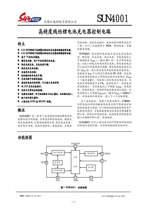
SUN4001高精度线性锂电池充电器控制电路特点4.2V 单节锂离子或锂聚合物电池充电器的理想控制电路;高于1%的电压精度;预充电过程,用户可改变预充电电流; 恒定电流充电,充电电流可调; 恒定电压充电过程; 自动再充电过程;充电过程中的温度监控;动态的电池内阻补偿,可以减少充电时间; 双LED 充电状态指示; 电池不正常状态的检测;电源电压低时,处于低功耗的Sleep 模式,电池漏电流小; 极少的外围元器件;小型化的SOP8或MSOP8 封装;概述SUN 4001是一款专门为高精度的线性锂电池充电器而设计的电路,非常适合那些低成本、便携式的充电器使用。
它集高精度预充电、恒定电流充电、恒定电压充电、电池状态检测、温度监控、充电结束低泄漏、充电状态指示、电池内阻补偿等性能于一身,可以广泛地使用于PDA 、移动电话、手持设备等领域。
SUN 4001通过检测电池电压来决定其充电状态:预充电、恒流充电、恒压充电。
当电池电压小于阈值电压V MIN (一般为3V )时,处于预充电状态,以较小的电流对电池进行充电,预充电的电流可以通过外部电阻进行调整。
预充电使电池电压达到V MIN 后,进入恒定电流充电的快速充电状态,充电电流I REG 可以通过外围电阻R1调整,恒定电流充电使电池电压上升到恒定电压充电电压V REG (一般为4.2V )。
然后进入恒定电压充电状态,充电电压的精度优于±1%,在该状态下,充电电流将逐渐减小,当充电电流小于阈值I TERM ,充电结束。
充电结束后,将始终对电池电压进行监控,当电池电压小于阈值V RECHG (一般为V REG -125mV )时,对电池进行再充电,进入下一个充电周期。
为了安全起见,在整个充电过程中,SUN4001利用电池内部的热敏电阻和适当的外围电阻对电池的温度进行监控,可以使电池的温度控制在用户设置的范围内。
当电池温度超过设置的范围0.5秒钟以后,将停止对电池充电;电池温度回到设置范围以内0.5秒钟以后,充电继续。
民航空管系统中市电及应急电源联动情况分析

民航空管系统中市电及应急电源联动情况分析发布时间:2021-07-15T08:07:52.963Z 来源:《防护工程》2021年8期作者:李冬俊[导读] 供电保障作为一切保障的基础,其重要性不言而喻,尤其是在民航空管系统中更是重中之重。
南方地区雷雨大风等而恶劣天气频繁,市电中断经常发生。
若因供电故障导致空管系统无法正常运行,会引发严重的后果。
因此,如何配置空管系统中市电及应急电源的联动情况将直接影响供电保障质量。
基于此,本文主要通过本单位供电保障要求和联动情况配置思路分析,为各兄弟单位提供供电保障参考。
中国民用航空中南地区空中交通管理局广西分局广西南宁 530000摘要:供电保障作为一切保障的基础,其重要性不言而喻,尤其是在民航空管系统中更是重中之重。
南方地区雷雨大风等而恶劣天气频繁,市电中断经常发生。
若因供电故障导致空管系统无法正常运行,会引发严重的后果。
因此,如何配置空管系统中市电及应急电源的联动情况将直接影响供电保障质量。
基于此,本文主要通过本单位供电保障要求和联动情况配置思路分析,为各兄弟单位提供供电保障参考。
关键词:民航空管系统;联动;供电保障0前言随着人民生活说平的不断提高,航空业不断发展,民航控管系统中的设备不断增多,其对供电保障的要求也在不断的提高。
根据供配电配置指导材料要求,空管通信导航监视设施设备负荷保障等级分为空管一级供电保障和空管二级供电保障。
民航广西空管分局空管小区作为一级保障,采用两路独立的10KV专线并列运行保障,每一路供电容量均满足所有负荷需求,且留有冗余,每路低压配备1台柴油发电机(以下简称油机)作为应急电源。
根据运行要求调整好市电和应急电源间的联动关系将能大大提高供电可靠性。
1主要供电保障设备型号及参数由于各单位建设时间都不相同,供电保障设备型号也参差不齐,但实现的功能大同小异,主要包括两路市电之间的联络,市电和应急电源之间的切换等。
现已本单位空管小区供电保障设备型号及参数为例,其供电情况如图1所示。
