MVI56-MCM简介
VMIVME-5565-000000中文资料

GE Fanuc Automation•VMEbus transfer rate 40 Mbyte/s•port for Windows NT ®, Windows ®2000,VxWorks ®, and Linux®VMIVME-5565 SpecificationsUltrahigh Speed Fiber-OpticReflective Memory with InterruptsFeatures:• High speed, easy to use fiber-optic network (2.12 Gbaud serially)• Data written to memory in one node is also written to memory in all nodes on the network • Up to 256 nodes• Connection with multimode fiber up to 300m, single mode fiber up to 10km• Dynamic packet size, 4 to 64 bytes of data• Network transfer rate 43 Mbyte/s (4 byte packets) to 174 Mbyte/s (64 byte packets) • 64 Mbyte or 128 Mbyte SDRAM Reflective Memory• Two independent DMA channels• Any node on the network can generate an interrupt in any other node on the network or in all network nodes with a single command • Error detectionfor extra error suppression • Redundant transfer mode • No processor overhead• No processor involvement in the operation of the network • VMISFT-RFM2G network and shared memory driver includedOperating system supFiber-Optic Cable Assemblies A B C D E F VMICBL-000-F5 – 0 0 0 0 ABC = Cable Lengths000 = .5 ft (0.15m) 011 = 350 ft (106.68m)001 = 1 ft (.31m) 012 = 500 ft (152.15m)002 = 5 ft (1.52m) 013 = 574 ft (175m)003 = 10 ft (3.04m) 014 = 656 ft (200m)004 = 25 ft (7.62m) 015 = 820 ft (250m)005 = 50 ft (15.24m) 016 = 1,000 ft (304.30m)006 = 80 ft (24.40m) 017 = 1,148 ft (350m)007 = 100 ft (30.49m) 018 = 1,312 ft (400m)008 = 150 ft (45.72m) 019 = 1,500 ft (456.45m)009 = 200 ft (60.98m) 020 = 1,640 ft (500m)010 = 250 ft (76.20m)DEF = 0 (Options reserved for future use)For Ordering Information, Call:1-800-322-3616 or 1-256-880-0444 • FAX (256) 882-0859Email: info.embeddedsystems@Web Address: /embeddedCopyright © 2005 by GE Fanuc Embedded SystemsSpecifications subject to change without notice. Functional CharacteristicsIntroduction:VMIVME-5565 is the VMEbus member of theGE Fanuc Embedded Systems VMIxxx-5565 family of Reflective Memory real-time network products. The other members of the family are VMIVME-5565, PCI mezzanine card (PMC), and VMIPCI-5565, the PCI-compatible board. All three of these products are network compatible, and may be integrated into a network in any combination. This family of products allows computers, workstations, PLCs, and other embedded controllers with dissimilar operating systems, or no operating system at all, to share data in real time.To the local node, the Reflective Memory board appears as shared memory. Data can be written to or read from the memory by any level of software, including the application itself. Data written to the Reflective Memory in one node is transported by the network hardware to all other nodes, and placed in the same address on those node’s Reflective Memory boards. This transport of data is accomplished without the involvement of the processors on any node. Using this system, all nodes on the network have a local copy of shared data available for immediate access.Product Overview: The Reflective Memory concept provides a very fast and efficient way of sharing data across distributed computer systems.GE Fanuc Embedded Systems’ VMIVME-5565 Reflective Memory interface allows data to be shared between up to 256 independent systems (nodes) at rates up to 174 Mbyte/s. Each Reflective Memory board can be configured with either64 Mbyte or 128 Mbyte of onboard SDRAM. The local SDRAM provides fast Read access times to stored data. Writes are stored in local SDRAM and broadcast over a high speed fiber-optic data path to other Reflective Memory nodes. The transfer of data between nodes is software transparent, so no I/O overhead is required. Transmit and Receive FIFOs buffer data during peak data rates to optimize processor and bus performance to maintain high data throughput.The Reflective Memory also allows interrupts to one or more nodes by writing to a byte register. These interrupt (four levels, each user definable) signals may be used to synchronize a system process, or used to follow any data. The interrupt always follows the data to ensure the reception of the data before the interrupt is acknowledged.Each node on the system has a unique identification number between 0 and 255. The node number is established during hardware system integration by a series of onboard switches. This node number can be read by software by accessing an onboard register. In some applications, this node number would be useful in establishing the function of the node.Link Arbitration:The VMIVME-5565 system is a fiber-optic daisy chain ring as shown in Figure 1. Each transfer is passed from node-to-node until it has gone all the way around the ring and reaches the originating node. Each node retransmits all transfers that it receives except those that it originated. Nodes are allowed to insert transfers between transfers passing through.Interrupt Transfers:The VMIVME-5565 provides four network interrupts. Any processor can generate an interrupt on any other node on the network. In addition, any processor can generate an interrupt on all nodes on the network with a single register write.In response to this interrupt register write, the sending VMIVME-5565 issues a special packet over the network, which contains the command strobe, the sender node ID, the destination node ID, and 32 bits of data. When a receiving node detects the proper combination of destination node ID and command strobe, it stores the sender note ID and the data in one of four 127 location-deep FIFOs. The four FIFOs correspond to the four interrupts. Upon storing this information in a FIFO, the receiving node issues an interrupt to the local processor if it has been software-enabled. The 32 bits of data stored in the FIFO is user-definable and typically is treated as an interrupt vector. As part of an interrupt service routine, the local processor reads this information out of the FIFO and acts accordingly.Ordering OptionsMay 13, 2005 800-005565-000 E A B C D E F VMIVME-5565 – 1 0 0 0A = Memory Options0 = 64 Mbyte1 = 128 MbyteB = FIFOs0 = Reserved1 = 4 K FIFOsC = Transmission Mode0 = Multimode1 = Single ModeDEF = 0 (Options reserved for future use)Simplex Cable SpecificationsFiber-Optic Cable – Multimode; (62.5 Micron core)VMEbus Initiator/DMA Capabilities:The VMIVME-5565 supports DMA operations. The DMA sequence is initialized by control register writes to the VMIVME-5565 by the host. Therefore, the VMIVME-5565 becomes a VMEbus initiator and moves the specified block of data up to 64 Mbyte without further host intervention. The architecture ensures that the VMIVME-5565 does not monopolize the VMEbus and causes theVMIVME-5565’s DMA engine to automatically split large blocks in small bursts. The VMIVME-5565 can be programmed to issue a VMEbus interrupt upon completion of DMA process. There are two independent DMA engines, each capable of reading or writing. It is possible for a read DMA and a write DMA to occur simultaneously.Error Management:Errors are detected by the VMIVME-5565 with the use of the error detection facilities of the Fiber Channel encoder/decoder and additional cyclic redundant encoding and checking. When a node detects an error, the erroneous transfer is removed from the system and an interrupt is generated, if enabled.Protection Against Lost Data: The product is designed to prevent the FIFOs from becoming full and overflowing. It is important to note the only way that data can start to accumulate in FIFOs is for data to enter the node at a rate greater than the network data rate. Since data can enter from the fiber and from the VMEbus, it is possible to exceed these rates. If the transmit FIFO becomes almost full, a bit in the Status Register is set. This is an indication to the node’s software that subsequent WRITEs to the Reflective Memory should be suspended until the FIFO is less than half-full. Once the transmit FIFO is almost full, writes to the Reflective Memory will be acknowledged with an interrupt. No data will be lost.If the receive FIFO is allowed to become almost full, there is a danger the receiver FIFO can overflow resulting in data loss. In order to prevent this situation, the board will not respond to Read or Write commands which if occurs for a long period of time will cause the system controller to declare a time out. Redundant Transfer Mode: The VMIVME-5565 can optionally be placed in the redundant transfer mode by the removal of a board jumper shunt. While in the redundant transfer mode, each packet sent on the network by the transmitter is sent twice, regardless of the dynamic packet size. The receiving circuitry of each node on the network evaluates each of the redundant transfers. If no errors are detected in the first transfer, it is used to update the onboard memory and the second transfer is discarded. If, however, the first transfer does contain an error, the second transfer is used to update the onboard memory provided it has no transmission error. In the remote chance that both redundant transfers contain an error, both transfer is used and the data is completely removed from the network.The redundant transfer mode greatly reduces the chance that any data is dropped from the network. However, the redundant transfer mode also reduces the effective network transfer rates. The single Lword (4 byte) transfer rate drops to approximately 20 Mbyte/s. The 16 Lword (64 byte) transfer rate drops to the redundant rate of 87 Mbyte/s. Network Monitor:There is a bit in the Status Register that can be used to verify that data is traversing the ring (that is, the ring is not broken). This can also be used to measure network latency.VMISFT-RFM2G Network and Shared Memory Driver:The VMISFT-RFM2G network and shared memory driver provides an applications program with three convenient methods for exchanging data among hosts connected to the same RFM network:1) Programmed I/O (Peek and Poke): An applications programcan treat the memory on the RFM device as ordinarymemory in which the program can use ordinary load andstore accesses.2) Direct Memory Access (DMA): Systems where theperformance penalty for individual bus accesses isunacceptably high, the driver utilizes the DMA featureavailable on some RFM devices in order to transfer data in variable-sized blocks. On UNIX systems, an applicationsprogram uses the familiar 1seek(2)/read(2)/write(2) system calls to perform the data movement, while on other operating systems a GE Fanuc Embedded Systems-provided application program interface (API) is used for datamovement.3) User Interrupts: The VMIPCI-5565 provides three networkinterrupts. Any processor can generate an interrupt on any other node on the network. In addition, any processor can generate an interrupt on all nodes on the network with asingle register write.Technical SpecificationsMemory Size:64 or 128 MbyteNetwork Nonredundant Transfer Rate: 43 Mbyte/s (single longword accesses) to 174 Mbyte/s (64 byte bursts)Network Redundant Transfer Rate:20 Mbyte/s (single longword accesses) to 87 Mbyte/s (64 byte bursts) CompatibilityVMEbus: This product complies with the VMEbus specification (ANSI/IEEE STD 1014-1987, IEC 821 and 297), with the following mnemonics:A32:A24:D32/D16/D08 (EO): Slave: 39/3D:09/0D Form factor: 6U CablesMultimode Fiber Cable:Small form factor (SFF)850nm, 970 ft, multimode LC connectorSingle Mode:Small form factor (SFF)1,300nm, single mode, 10km or 6.21 milesPhysical/Environmental Specifications Power Requirements:+5VDC (±5 percent), 5.0A maximumTemperature:Operating: 0 to +65° C with forced air coolingStorage: -40 to +85° CRelative Humidity: 20% to 80%, noncondensingMTBF:163,995 hours (Bellcore)Data TransfersData written into the Reflective Memory is broadcast to all nodes on the network without further involvement of the sending or receiving nodes. Data is transferred from memory locations on the sending nodes to corresponding memory locations on the receiving nodes.An illustration of a network example using Reflective Memory is shown in Figure 1.TrademarksWindows and Windows NT are registered trademarks of Microsoft Corporation. Other registered trademarks are the property of their respective owners.Figure 1. Network Example Using Reflective Memory SystemGE Fanuc Embedded Systems Information Centers Additional ResourcesAmericas:Huntsville, AL 1 800 322-36161(256)880-0444 Camarillo, CA 1 (805) 987-9300 Greenville, SC 1 (864) 627-8800 For more information, please visit theGE Fanuc Embedded Systems web site at: /embeddedEurope, Middle East and Africa: Edinburgh, UK 44 (131) 561-3520 Paris, France 33 (1) 4324 6007。
ABPLC系统1756模块接线状态说明书

1、AI专题正负极必须正确,否则没有信号。
正极对正极,负极对负极。
1756-IF16下图为差动输入状态:上图为单端输入,正负极接错,上位机没有数,首先看24V电源是否正常,即802PX 某个保险端子是否推入,保险是否损坏,然后看+级与—级是否接反(反接一下是否有数),拆下机柜内线用信号发生器发信号(看是否是PLC机柜问题)。
最后到现场拆下线,机柜内部线也拆下来,现场短接,用万用表在机柜端测电阻(校线看是否线用错了)2、AO专题AB的PLC板卡接线方式。
1756-OF4模拟量输出模块3、DI专题1756-IB32模块1、OK指示灯指示灯状态模板状态描述绿正常正常状态,可以支持多点传送。
绿闪烁异常模板通过了内部检测,但没有多点输入。
红异常需更换模板红闪烁异常上一次通讯超时2、I/O指示灯指示灯状态模板状态描述黄正常激活输入此模块为数字量输入模块,其特性如下图:看PLC模块显示是否有输入,查看24v电源是否送上。
然后用短接线发假信号,查看PX端子排上相应端子的保险端子是否正常。
4、DO专题24V电源直接进入DO输出板子的公共端,如果DO输出亮灯,但是在输出点没有24v 就要量DO板子的公共24v进线是否有电。
查看板子上部灯是否亮,亮说明有输出,在一次端子用万用表测电压应该为24V。
如果没有,查看PX端子排电源端子是否正常。
1756-OB321756-OW16I1756-OW16I数字量输出模块左边为24V接入,右侧为输出,如果左侧24V没供电,右侧即使指示灯亮了,也不会有输出。
5、RTD模块1756-IR6I铂电阻模块6、计数器模块1756-HSC 高速脉冲记数模块1756-HSC 模块应用下面状态知识LED 灯LED 灯显示 LED 灯颜色 指示灯意义 处理方法显示输入(A ,B ,Z ) 不亮输入端断开输入信号当前没有被使用 接线断开 如果你需要使用此输入信号,请查线黄色灯亮 输入信号正常显示输出(0,1,2,3) 不亮 输出端断开 输出信号当前没有被使用 如果你需要使用此输入信号,请查线黄色灯亮输出信号正常7、第三方通讯模块1756-MVI56MCM MODBUS 通讯模块1756-MVI56MCM 模块指示灯显示模块运行状态如下:LED灯显示颜色状态指示P1 绿色亮数据正通过配置/调试断口与远程终端传输不亮端口中没有数据传输P2 绿色亮数据正通过此断口与MODBUS网络传输不亮端口中没有数据传输P3 绿色亮数据正通过此断口与MODBUS网络传输不亮端口中没有数据传输APP 桔色亮模块工作正常不亮MVI56-MCM模块程序发现了它其中一个MODBUS通讯端口的通讯错误BP ACT 桔色亮此模块正在执行写操作不亮此模块正在执行读操作。
AB5000PLC MVI56MCM 配置

MVI56-MCM模块在ControlLogix 中的配置操作步骤如下:1、启动RSLogix 5000编程软件,1756-L55处理器位于第0槽,控制器名字为MVI56MCM。
1756-CNBR位于第2槽。
2、添加新模块MVI56-MCM,位于第11槽,配置如下:3、按照MVI56-MCM的DEMO程序,配置MCM1控制器标签。
4、修改MCM1.ModDef标签:其中WriteStartReg为0,写的起始地址;WriteRegCnt为600,写的数量;占用MCM内部地址0-4999中的0-599;其中ReadStartReg为600,读的起始地址;ReadRegCnt为600,读的数量;占用MCM内部地址0-4999中的600-1299;BPFail为3,CPU和MCM通讯失败后,是否继续通讯(次数);ErrStatPtr为1100,存放错误/状态数据的地址,与开放的写与读的地址大小有关,在这里不能超过600+600=1200。
5、配置ModBus端口地址(Port 0):Port[0].Enabled为1,使能位;Port[0].Type为0,Port 0为Master;波特率19200,无校验,8位数据位,1位停止位;Port[0].CmdCount为5,从主站到从站有5个命令。
Port[0].CmdErrPtr为1000,存放命令错误表,与开放的写与读的地址大小有关,在这里不能超过600+600=1200;Port[0].RespTO为1000ms,命令出错延时;Port[0].Retry_Count 为3,命令出错后请求重复的次数;Port[0].ErrorDelayCntr为22,命令出错计数。
6、配置主站到从站的命令(每个端口最大可以到100个命令):命令0:功能代码为3,从子站连续读寄存器地址,数量为10个,MCM内部地址为600-609,子站节点为1,子站ModBus开始地址为0,即40001-40010,读上来的数据存放在ReadData[0]- ReadData[9];命令1:功能代码为3,从子站连续读寄存器地址,数量为10个,MCM内部地址为610-619,子站节点为1,子站ModBus开始地址为10,即40011-40020,读上来的数据存放在ReadData[10]- ReadData[19];命令2:功能代码为3,从子站连续读寄存器地址,数量为40个,MCM内部地址为630-669,子站节点为1,子站ModBus开始地址为20,即40021-40060,读上来的数据存放在ReadData[30]- ReadData[69];其中MCM内部地址为620-629未使用。
ABPLC系统1756模块接线状态说明
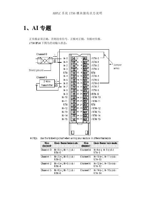
1、AI专题正负极必须正确,否则没有信号。
正极对正极,负极对负极。
1756-IF16下图为差动输入状态:上图为单端输入,正负极接错,上位机没有数,首先看24V电源是否正常,即802PX 某个保险端子是否推入,保险是否损坏,然后看+级与—级是否接反(反接一下是否有数),拆下机柜内线用信号发生器发信号(看是否是PLC机柜问题)。
最后到现场拆下线,机柜内部线也拆下来,现场短接,用万用表在机柜端测电阻(校线看是否线用错了)2、AO专题AB的PLC板卡接线方式。
1756-OF4模拟量输出模块3、DI专题1756-IB32模块1、OK指示灯指示灯状态模板状态描述绿正常正常状态,可以支持多点传送。
绿闪烁异常模板通过了内部检测,但没有多点输入。
红异常需更换模板红闪烁异常上一次通讯超时2、I/O指示灯指示灯状态模板状态描述黄正常激活输入此模块为数字量输入模块,其特性如下图:看PLC模块显示是否有输入,查看24v电源是否送上。
然后用短接线发假信号,查看PX端子排上相应端子的保险端子是否正常。
4、DO专题24V电源直接进入DO输出板子的公共端,如果DO输出亮灯,但是在输出点没有24v 就要量DO板子的公共24v进线是否有电。
查看板子上部灯是否亮,亮说明有输出,在一次端子用万用表测电压应该为24V。
如果没有,查看PX端子排电源端子是否正常。
1756-OB32 1756-OW16I1756-OW16I数字量输出模块左边为24V接入,右侧为输出,如果左侧24V没供电,右侧即使指示灯亮了,也不会有输出。
5、RTD模块1756-IR6I铂电阻模块6、计数器模块1756-HSC高速脉冲记数模块1756-HSC模块应用下面状态知识LED灯7、第三方通讯模块1756-MVI56MCM MODBUS通讯模块1756-MVI56MCM模块指示灯显示模块运行状态如下:8、以太网通讯模块1756-ENBT 以太网模板ABPLC系统1756模块接线状态说明。
MVI56-MCM培训教程

MVI56-MCM培训教程MVI56-MCM是毫升的一种常见控制模块,该模块可配置为采用多个通道的流量监测、计量和控制功能,支持DeltaV和Modicon Quantum彩色显示器。
MVI56-MCM培训教程为学习者提供了详细的关于该控制模块操作和应用的指导。
在开始MVI56-MCM培训教程之前,首先需要了解的是该控制模块的基本概念和应用。
MVI56-MCM可以通过将模拟信号转换为数字信号来测量和监测工业过程中的流量、压力、温度等参数,同时可以通过控制相关设备来实现对过程的自动控制。
在实际应用中,该控制模块主要应用于石油化工、制药、食品、污水处理等领域,有效帮助企业提高生产效率和质量。
MVI56-MCM培训教程主要包含以下三个部分:一、基础知识教学:在此部分中我们将学习MVI56-MCM的基础知识,包括接线、信号调试和常见故障排除等方面。
1. 模块的安装和连接:详细介绍模块的物理链接和电气连接方法;2. 信号的调试:学习如何诊断信号的弱点,如何改进调整信号上的误差;3. 故障排查:学习如何使用堆栈分析器,识别问题并迅速诊断和解决问题。
二、软件操作教学:此部分主要学习使用MVI56-MCM的软件以控制模块。
具体包括如下内容:1. 软件概述:MVI56-MCM的软件功能介绍,了解如何使用;2. 系统配置和设置:配置及组态MVI56-MCM模块和系统;3. 密码保护:软件密码设置和更改;4. 监测和诊断:软件中的过程诊断和维护功能。
三、应用实践教学:此部分主要通过案例分析的方法,实现学习者的应用实践教学。
具体包括如下内容:1. 流量和温度控制:通过模拟实验,学习如何使用MVI56-MCM来控制流量和温度;2. 节能方案实践:案例分析说明如何使用MVI56-MCM来实现企业节能方案;3. 分析反馈:通过案例分析,学习如何分析MVI56-MCM的反馈信号,并快速诊断和解决问题。
总结:MVI56-MCM培训教程涵盖了该控制模块的基础知识、软件操作和应用实践。
MVI56-MCM 培训教程
MVI56-MCM
MVI56-MCM Ladder Logic
1. 如右图创建新的模块,或从样例程序 中复制已经创建的MCM模块。
MVI56-MCM Ladder Logic
2. 如果是新创 建模块,则 需要选择的 模块类型是 1756MODULE。
MVI56-MCM Ladder Logic
8. MCM.P2Cmd定义 了P2端口上的 Modbus命令。 MCM.P2Cmd[0]这 条指令的含义是从 Modbus从站地址1 的40001开始,用 功能代码3读取10 个寄存器,所读的 数据放置在模块的 内部数据库600开 始。 每个端口最多100 条据先放到 模块内部数据 库
梯形程序处理完成 (样例程序已完成这部分功能)
设置模块的Modbus功能来实现
Simple Steps To Make Your Own MCM Ladder
总结: --- 从样例程序复制MCM模块到新程序 --- 复制 user-defined 数据类型
5. 然后复制样例程序中的tag到新的程序。需要复制的tag包括: ColdBoot(模块冷启动),WarmBoot(模块热启动)和 MCM。 如果新创建MCM tag,那就必须仔细参考样例程序和说明 书对新的MCM tag预先填写设置数据。
MVI56-MCM Ladder Logic
6. MCM.ModDef的数据设置。 此Tag设置模块的基本数据传送结构
MVI56-MCM Ladder Logic
12. ControlLogix Tag和模块的内部数据库的对应关系,以及数据流向。
MCM Module Modbus Network
Modbus Master Slave通信模块MVI56E-MCM MCMXT说明书

DATASHEETModbus Master/SlaveCommunication ModuleMVI56E-MCM/MCMXTThe MVI56E Communication Module allows for Modbus Master and/or Slaveconnectivity from Rockwell Automation® ControlLogix® processors to ModbusRTU/ASCII devices. Each MVI56E port can be configured as a Master or Slave.The MVI56E-MCM and MVI56E-MCMXT act as input/output modules on theControlLogix backplane, making Modbus data appear as I/O data to the processor.Two independently configurable serial ports can operate on the same or differentModbus networks. The MVI56E-MCM is designed for standard processapplications and the MVI56E-MCMXT is designed for the Logix-XT™ controlplatform, allowing it to operate in extreme environments. It can tolerate higheroperating temperatures, and has conformal coating to protect it from harsh orcaustic conditions.Features BenefitsBackward Compatibility ♦All MVI56E products are backward-compatible with earlier MVI56 modules allowing directreplacement without the need to change existing controller programs10,000 Word Database ♦Allows you to gather more data from your devices, which improves operationalperformance♦Enjoy Enhanced features and flexibility without incurring expensive reprogramming costs Add-On Instruction ♦Module configuration stored within the RSLogix™ 5000 project (ACD file)♦No additional programming or configuration software is required♦Add-On Instruction for RSLogix 5000 version 16 or higher cuts development time andcostsCIPconnect® Enabled ♦Facilitates remote user access across the ControlLogix backplane through RockwellAutomation’s 1756-ENBT module♦Configure, diagnose, and analyze process data and communications status♦Bridge through multiple ENBT/CNBT links to connect to MVI56E-MCMs installed in remotechassis for configuration and diagnosticsAdd-On Profile ♦Simplifies adding the module in an RSLogix 5000 projectConfigurationThe module configuration is defined in the Add on Instruction. The AOI is fullycommented, and includes user-defined data types, ladder rungs and controller tags. TheAOI can be used without modification for most application.The MVI56E-MCM User Manual and sample configuration provide a quick and easyexample with step-by-step instructions on how to move data through the module fromthe Modbus network to the processor.General Specifications∙Backward-compatible with previous MVI56-MCM version∙Single Slot - 1756 ControlLogix® backplane compatible∙10/100 MB Ethernet port for network configuration and diagnostics with Auto Cable Crossover Detection∙User-definable module data memory mapping of up to 10,000 16-bit registers∙4-character, scrolling, alphanumeric LED display of status and diagnostic data in plain English∙ProSoft Discovery Service (PDS) software finds the module on the network and assigns a temporary IP address to facilitate module accessFunctional SpecificationsThe MVI56E-MCM will operate on a Local or Remote rack (For remote rack applications with smaller data packet size please refer to the MVI56E-MCMR product)∙Supports Enron version of Modbus protocol for floating-point data transactions∙PCB includes powerful Modbus network analyzer∙Special functions (command control, event commands, status, and so on) are supported by message transfer (unscheduled) using the MSG instruction∙Error codes, network error counters, and port status data available in user data memorySlave SpecificationsThe MVI56E-MCM module accepts Modbus function code commands of 1, 2, 3, 4, 5, 6, 8, 15, 16, 17, 22, and 23 from an attached Modbus Master unit. A port configured as a Modbus Slave permits a remote Master to interact with all data contained in the module. This data can be derived from other Modbus Slave devices on the network, through a Master port, or from the ControlLogix processor.Master SpecificationsA port configured as a virtual Modbus Master device on the MVI56E-MCM module actively issues Modbus commands to other nodes on the Modbus network. Up to 325 commands are supported on each port. Additionally, the Master ports have an optimized polling characteristic that polls Slaves with communication problems less frequently. The ControlLogix processor ladder logic can issues commands directly from ladder logic or actively select commands from the command list to execute under ladder logic control.ControlLogix™ Modbus IntegrationGeneral Modbus SpecificationsCommunication Parameters Baud Rate: 110 baud to 115.2 kbpsStop Bits: 1 or 2Data Size: 7 or 8 bitsParity: None, Even, OddRTS Timing delays: 0 to 65535 milliseconds Modbus Modes RTU mode (binary) with CRC-16ASCII mode with LRC error checkingFloating Point Data Floating point data movement supported, includingconfigurable support for Enron and DanielimplementationsModbus Function Codes 1: Read Coils Status2: Read Input Status3: Read Holding Registers4: Read Input Registers5: Force (Write) Single Coil6: Preset (Write) Single Register8: Diagnostics15: Force (Write) Multiple Coils16: Preset (Write) Multiple Data Registers17: Report Slave ID22: Mask Write 4x Register23: Read/Write 4x RegistersModbus Master SpecificationsCommand List Up to 325 commands per Master port, each fullyconfigurable for function code, slave address, registerto/from addressing and word/bit count.Optimized Polling Configuration options allow Master ports andcommands to be optimized to poll slaves withcommunication problems less frequently.Command Status/Error Monitoring Command Status or Error codes are generated for each command as it executes, allowing careful monitoring of communication health between the Master and its Slaves.Slave Polling Control Master Port maintains a Slave Status list of all networkSlaves. Polling of each Slave may be disabled andenabled using this list.Modbus Slave SpecificationsFull Memory Access A port configured as a Modbus Slave permits a remoteMaster to read from or write to any of the 10,000registers that make up the user memory database. Multi-source Slave Data Data presented at the Slave port can be derived fromother Modbus Slave devices on a different networkthroug h the module’s Master port or from the processortag database.Node Address 1 to 247 (software selectable)Status Data Slave port error codes, counters and statuses areavailable separately for each port when configured as aSlave® products areHardware SpecificationsGeneralSpecification DescriptionBackplane Current Load 800 mA @ 5 Vdc3 mA @ 24 VdcOperating Temperature 0°C to 60°C (32°F to 140°F) - MVI56E-MCM-25°C to 70°C (-13°F to 158°F) - MVI56E-MCMXT Storage Temperature -40°C to 85°C (-40°F to 185°F)Extreme/Harsh Environment MVI56E-MCMXT comes with conformal coating Shock 30 g operational50 g non-operationalVibration: 5 g from 10 to 150 HzRelative Humidity 5% to 95% (without condensation)LED Indicators Battery Status (ERR)Application Status (APP)Module Status (OK)4-Character, Scrolling, Alpha-Numeric LED Display Shows Module, Version, IP, Port Master/Slave Setting, Port Status, and Error InformationDebug/Configuration Ethernet port (E1 - Config)Ethernet Port 10/100 Base-T, RJ45 Connector, for CAT5 cableLink and Activity LED indicatorsAuto-crossover cable detectionSerial Application ports (P1 & P2)Full hardware handshaking control, providing radio, modem, and multi-drop supportSoftware configurable communication parameters Baud rate: 110 baud to 115.2 kbpsRS-232, 485 and 422Parity: none, odd or evenData bits: 5, 6, 7, or 8Stop bits: 1 or 2RTS on/off delay: 0 to 65535 millisecondsSerial Applications Ports (P1, P2) RJ45 (DB-9M with supplied adapter cable) Configurable RS-232 hardware handshaking500V Optical isolation from backplaneRS-232, RS-422, RS-485 jumper-select, each port RX (Receive) and TX (Transmit) LEDs, each portShipped with Unit RJ45 to DB-9M cables for each serial port5 foot Ethernet Straight-Thru Cable (Gray) Agency Approvals and CertificationsAgencyRoHSATEXCSACECSA CB SafetycULusGOST-RLloyds® offers a full。
MVI56E_MCM_Setup_Guide
MVI56E-MCM /MCMXTControlLogix PlatformModbus Communication ModuleFebruary15, 2010SETUP GUIDEImportant Safety Information - MVI56E and MVI56E-XT ModulesNorth America WarningsA Warning - Explosion Hazard - Substitution of components may impair suitability for Class I, Division 2.B Warning - Explosion Hazard - When in Hazardous Locations, turn off power before replacing or rewiringmodules.Warning - Explosion Hazard - Do not disconnect equipment unless power has been switched off or the area is known to be nonhazardous.C Suitable for use in Class I, Division 2 Groups A, B, C, and D, T5 Hazardous Locations or Non-HazardousLocations.ATEX Warnings and Conditions of Safe Usage:Power, Input, and Output (I/O) wiring must be in accordance with the authority having jurisdictionA Warning - Explosion Hazard - When in hazardous locations, turn off power before replacing or wiring modules.B Warning - Explosion Hazard - Do not disconnect equipment unless power has been switched off or the area isknown to be non-hazardous.C These products are intended to be mounted in an IP54 enclosure. The devices shall provide external means toprevent the rated voltage being exceeded by transient disturbances of more than 40%. This device must be used only with ATEX certified backplanes.D DO NOT OPEN WHEN ENERGIZED.RatingsBackplane Current Load: 800 mA @ 5 V DC; 3mA @ 24V DCOperating Temperature:For standard MVI56E modules: 0° to 60°C (32 to 140°F);For MVI56E XT (conformal coated): -25° to 70°C (-13° to 158°F)Storage Temperature: -40° to 85°C (-40 to 185°F)Shock: 30g Operational; 50g non-operational; Vibration: 5 g from 10 to 150 HzRelative Humidity 5% to 95% (non-condensing)All phase conductor sizes must be at least 1.3 mm (squared) and all earth ground conductors must be at least 4mm (squared).MVI56E XT module comes with conformal coating installed.MarkingsANSI / ISA ISA 12.12.01 Class I Division 2, GPs A, B, C, DCSA/cUL C22.2 No. 213-M1987CSA CB Certified IEC61010ATEX EN60079-0 Category 3, Zone 2EN60079-15243333 E183151CL I Div 2 GP A, B, C, DTemp Code T4II 3 GEx nA nL IIC T4 X-20° C <= Ta <= 70° CII – Equipment intended for above ground use (not for use in mines).3 – Category 3 equipment, investigated for normal operation only.G – Equipment protected against explosive gasses.Battery Life AdvisoryThe module uses a rechargeable Lithium Vanadium Pentoxide battery to backup the real-time clock and CMOS settings. The battery itself should last for the life of the module. However, if left in an unpowered state for 14 to 21 days, the battery may become fully discharged and require recharging by being placed in a powered-up ControlLogix chassis. The time required to fully recharge the battery may be as long as 24hours.Once it is fully charged, the battery provides backup power for the CMOS setup and the real-time clock for approximately 21 days. Before you remove a module from its power source, ensure that the battery within the module is fully charged (the BATT LED on the front of the module goes OFF when the battery is fully charged). If the battery is allowed to become fully discharged, the module will revert to the default BIOS and clock settings.Note: The battery is not user-replaceable or serviceable.ProSoft Technology® Product DocumentationIn an effort to conserve paper, ProSoft Technology no longer includes printed manuals with our product shipments. User Manuals, Datasheets, Sample Ladder Files, and Configuration Files are provided on the enclosed CD-ROM, and are available at no charge from our web site: Printed documentation is available for purchase. Contact ProSoft Technology for pricing and availability.North America: +1.661.716.5100Asia Pacific: +603.7724.2080Europe, Middle East, Africa: +33 (0) 5.3436.87.20Latin America: +1.281.298.9109Your Feedback PleaseWe always want you to feel that you made the right decision to use our products. If you have suggestions, comments, compliments or complaints about the product, documentation, or support, please write or call us.ProSoft Technology5201 Truxtun Ave., 3rd FloorBakersfield, CA 93309+1 (661) 716-5100+1 (661) 716-5101 (Fax)support@Copyright © ProSoft Technology, Inc. 2009. All Rights Reserved.MVI56E-MCM / MCMXT Setup GuideNovember 06, 2009ProSoft Technology ®, ProLinx ®, inRAx ®, ProTalk®, and RadioLinx ® are Registered Trademarks of ProSoft Technology, Inc. All other brand or product names are or may be trademarks of, and are used to identify products and services of, their respective owners.Contents MVI56E-MCM / MCMXT ♦ ControlLogix Platform Setup Guide Modbus Communication ModuleProSoft Technology, Inc. Page 5 of 58November 6, 2009 ContentsImportant Safety Information - MVI56E and MVI56E-XT Modules (2)Battery Life Advisory...........................................................................................................................3 ProSoft Technology ® Product Documentation....................................................................................3 Your Feedback Please (3)1 Scope71.1 What's New?.............................................................................................................7 1.2 Learning Objectives...................................................................................................8 1.3 ProSoft Technology Documentation.........................................................................8 1.4Prerequisites (9)2 Before You Begin112.1 System Requirements.............................................................................................11 2.2 Required Items........................................................................................................12 2.3Sample Files (12)3 Install the Configuration Tools133.1Install ProSoft Discovery Service (13)4 The Sample Application154.1 About the MODBUS Protocol..................................................................................15 4.2 General Overview....................................................................................................16 4.3 Architecture.............................................................................................................17 4.4Memory Map (19)5 Procedures215.1 Physical Setup.........................................................................................................21 5.2 Connect your PC to the ControlLogix Processor....................................................34 5.3 Download the Sample Program to the Processor...................................................35 5.4 Set up the Read and Write Database Areas...........................................................36 5.5 Reboot the Module to Transfer New Parameter Values.........................................41 5.6 Configure the Quantum Processor as a Modbus Slave..........................................41 5.7 Connect the MVI56E-MCM Module to the Quantum Processor.............................42 5.8Verify Communication (43)6 Building on Success496.1Frequently Asked Questions (49)MVI56E-MCM / MCMXT ♦ ControlLogix Platform Contents Modbus Communication Module Setup Guide 7Glossary of Terms 53Index 57Page 6 of 58 ProSoft Technology, Inc.November 6, 2009Scope MVI56E-MCM / MCMXT ♦ ControlLogix Platform Setup Guide Modbus Communication ModuleProSoft Technology, Inc. Page 7 of 58November 6, 2009 1 ScopeIn This ChapterWhat's New?...........................................................................................7 Learning Objectives.................................................................................8 ProSoft Technology Documentation........................................................8 Prerequisites . (9)This document acts as a tutorial, providing step-by-step instructions on how toread and write bi-directional data from one network device to another network device using the MVI56E-MCM / MCMXT.1.1 What's New?MVI56E products are backward compatible with existing MVI56 products,ladder logic, and module configuration files already in use. Easily swap and upgrade to benefit from an array of new features designed to improve interoperability and enhance ease of use.Web Server: The built-in web server and web page allow access to manualsand other tools previously provided only on a product CD-ROM or from the ProSoft Technology ® web site.ProSoft Configuration Builder (PCB): Microsoft Windows ®-based utilitysoftware for diagnostics. Connect through the module's Ethernet port or use CIPconnect ® to access troubleshooting features and functions.ProSoft Discovery Service (PDS): New Windows-based utility software tofind and display a list of MVI56E modules on the network and to temporarily change a module's IP address to be able to connect with a module's web page.CIPconnect-enabled: Allows PC-to-module diagnostics from the Ethernetnetwork through a ControlLogix ® 1756-ENxT EtherNet/IP™ module.Personality Card: An industrial-grade compact flash memory card storingthe module’s Ethernet settings, allowing quick and easy replacement. LED Scrolling Diagnostic Display: 4-character, alphanumeric display,providing English messages for status and alarm data, and for processor and network communication status.XT series for Extreme Environments: The MVI56E-MCMXT is part of thenew XT series, designed to work at extreme temperatures and in harsh or caustic environments. XT series modules operate over a wider temperature range than the standard MVI56E series. The XT series also come with conformal coating to protect module components from corrosive environmental elements.MVI56E-MCM / MCMXT ♦ ControlLogix Platform Scope Modbus Communication Module Setup GuidePage 8 of 58 ProSoft Technology, Inc.November 6, 20091.2 Learning ObjectivesWhen you have completed all the steps in this Setup Guide, you will havelearned how to Use the sample application (page 15)Install the MVI56E-MCM setup and diagnostic software (page 13) Install the MVI56E-MCM module (page 21)Import the Add-On Instruction to the processor (page 35)Configure the Modbus Master using the sample Add-On Instruction Configure the Modbus Slave (page 41)Verify the MVI56E-MCM module communication status (page 43)1.3 ProSoft Technology DocumentationProSoft Technology provides the following documentation (manuals) with yourMVI56E-MCM.Electronic documentation (on the MVI56E-MCM web page)Setup Guide: (this manual) Describes a sample application, and takes youthrough the steps necessary to install, configure, and verify the correct operation of the moduleUser Manual: Detailed reference guide to the module, protocol configuration,functional overview, diagnostics and troubleshooting procedures, and product specificationsDatasheet: Brief description of the module hardware and protocolimplementation, as well as general and functional specifications Additional documentation, tools, and product supportWeb Site Support: Visit the ProSoft Technology web site at to download additional documentation, tools, and application information.Email Technical Support: Send your support questions to Support@.Telephone Support: Please call ProSoft Technology Technical Support at:(Country Code 1+) 661-716-5100. Support is available 24 hours a day, 7 days a week. ProSoft Technology telephone support is free and unlimited.Scope MVI56E-MCM / MCMXT ♦ ControlLogix Platform Setup Guide Modbus Communication ModuleProSoft Technology, Inc. Page 9 of 58November 6, 2009 1.4 PrerequisitesTo get the most benefit from this Setup Guide , you should have the followingskills:Rockwell Automation ® RSLogix™ 5000 software: launch the program,configure, and transfer the Add-On Instruction (or ladder logic) Sample Application program to the processorMicrosoft Windows ®: install and launch programs, execute menucommands, navigate dialog boxes and enter data.Serial data communication: correctly configure data communicationparameters such as baud rate, parity, data bits, and so on, using the documentation for the devices connected to the networkEthernet networking: connect the MVI56E-MCM module to an Ethernetnetwork using a valid IP address and subnet maskHardware installation and wiring : install the module and safely connectModbus Master/Slave and ControlLogix devices to a power source and to the MVI56E-MCM module’s serial portsMVI56E-MCM / MCMXT ♦ ControlLogix Platform Scope Modbus Communication Module Setup Guide Page 10 of 58 ProSoft Technology, Inc.November 6, 2009Before You Begin MVI56E-MCM / MCMXT ♦ ControlLogix Platform Setup Guide Modbus Communication Module YouBegin2 BeforeIn This ChapterSystem Requirements (11)Required Items (12)Sample Files (12)Requirements2.1 SystemThe MVI56E-MCM module requires the following minimum hardware andsoftware components:Rockwell Automation® ControlLogix® processor (firmware version 10 orhigher), with compatible power supply, and one free slot in the rack for theMVI56E-MCM module. The module requires 800mA of available 5 V DCpowerRockwell Automation RSLogix™ 5000 programming softwareo Version 16 or higher required for Add-On Instructiono Version 15 or lower must use Sample Ladder, available fromRockwell Automation RSLinx® communication software version 2.51 or higherProSoft Configuration Builder (PCB) (included)ProSoft Discovery Service (PDS) (included in PCB)Pentium® II 450 MHz minimum. Pentium III 733 MHz (or better)recommendedSupported operating systems:o Microsoft Windows® Vistao Microsoft Windows XP Professional with Service Pack 1 or 2o Microsoft Windows 2000 Professional with Service Pack 1, 2, or 3o Microsoft Windows Server 2003128 Mbytes of RAM minimum, 256 Mbytes of RAM recommended100 Mbytes of free hard disk space (or more based on applicationrequirements)256-color VGA graphics adapter, 800 x 600 minimum resolution (True Color 1024 × 768 recommended)CD-ROM driveNote: The Hardware and Operating System requirements in this list are the minimumrecommended to install and run software provided by ProSoft Technology®. Other third partyapplications may have different minimum requirements. Refer to the documentation for any thirdparty applications for system requirements.MVI56E-MCM / MCMXT ♦ ControlLogix Platform Before You BeginModbus Communication Module Setup GuidePage 12 of 58 ProSoft Technology, Inc.Note: You can install the module in a local or remote rack. For remote rack installation, the module requires EtherNet/IP or ControlNet communication with the processor.2.2 Required ItemsThis Setup Guide uses a sample application that shows you how to establishcommunication between the MVI56E-MCM module (Master Port) and a Modbus Slave device. The sample application requires the following equipment.Item Description MVI56E-MCMModbus Communication Module1756-L63 ControlLogix processor 1756-A7/B ControlLogix rack 1756-PA72/B ControlLogix rack power supply CPU434 12A Quantum processor (Modbus device) CPS 114 20 Quantum power supply140XBP01000 Quantum rackEthernet cable Ethernet cable to connect MVI56E-MCM module to Ethernet networkfor diagnostics (supplied with the module)Serial cableSerial cable to connect MVI56E-MCM module to Modbus serial network2.3 Sample FilesThe following file is required for this procedure:Item Description MVI56(E)MCM_AddOn_Rung_<Version #>.L5XSample rung import file containing Add-On InstructionThis procedure requires RSLogix 5000 version 16 (or later), which supports Add-On Instructions. The sample MVI56(E)MCM_AddOn_Rung_<Version #>.L5X Add-On Instruction file contains all elements required for the MVI56E-MCM module to function.User-defined Data Types (UDTs) Add-On Instruction (AOI) Ladder rung with AOI Controller tagsThe AOI L5X rung import file is located on the module’s built-in web page. Note: For RSLogix v15 (or older) applications, please refer to the MVI56E-MCM User Manual for information on how to use the sample ladder logic.Install the Configuration Tools MVI56E-MCM / MCMXT ♦ ControlLogix PlatformSetup Guide Modbus Communication Module3 Install the Configuration ToolsIn This ChapterInstall ProSoft Discovery Service (13)3.1 Install ProSoft Discovery ServiceYou must install the ProSoft Discovery Service (PDS) software in order toconfigure the MVI56E-MCM module's temporary IP address. This will allow you to access the module's web page to download product documentation and sample files and to set the module's permanent network address and settings. To install ProSoft Discovery Service from the CD-ROM1 Insert the ProSoft Solutions CD-ROM into the CD drive of your PC. Wait forthe startup screen to appear.2 On the startup screen, click I NSTALL P RO S OFT D ISCOVERY S ERVICE . Thisaction starts the installation wizard.3 Click N EXT on each page of the installation wizard. Click F INISH on the lastpage of the wizard.MVI56E-MCM / MCMXT ♦ ControlLogix Platform Install the Configuration Tools Modbus Communication Module Setup Guide Page 14 of 58 ProSoft Technology, Inc.The Sample Application MVI56E-MCM / MCMXT ♦ ControlLogix Platform Setup Guide Modbus Communication ModuleApplication4 TheSampleIn This ChapterAbout the MODBUS Protocol (15)General Overview (16)Architecture (17)Memory Map (19)4.1 About the MODBUS ProtocolMODBUS is a widely-used protocol originally developed by Modicon in 1978.Since that time, the protocol has been adopted as a standard throughout theautomation industry.The original MODBUS specification uses a serial connection to communicatecommands and data between Master and Slave devices on a network. Laterenhancements to the protocol allow communication over other types of networks.MODBUS is a Master/Slave protocol. The Master establishes a connection to theremote Slave. When the connection is established, the Master sends theMODBUS commands to the Slave. The MVI56E-MCM module can work as aMaster and as a Slave.The MVI56E-MCM module also works as an input/output module between itselfand the Rockwell Automation backplane and processor. The module uses aninternal database to pass data and commands between the processor andMaster and Slave devices on MODBUS networks.MVI56E-MCM / MCMXT ♦ ControlLogix Platform The Sample ApplicationModbus Communication Module Setup GuidePage 16 of 58 ProSoft Technology, Inc.4.2 General OverviewThis Setup Guide shows you how to configure the MVI56E-MCM module andestablish communication with a Modbus device (a Quantum processor, for this example).The MVI56E-MCM Port 1 (P1) will be configured as a Modbus Master device. The Quantum processor will operate as a Modbus Slave device (Modbus Comm 1). The MVI56E-MCM will be configured to send two Master commands to the Modbus Slave device:Write 10 words (Modbus Function 16 - Preset [Write] Multiple RegistersRead 10 words (Modbus Function 3 -Read Holding RegistersWhen you finish the steps in this Setup Guide, you will have enough information to set up your own application.The Sample Application MVI56E-MCM / MCMXT ♦ ControlLogix Platform Setup Guide Modbus Communication Module4.2.1 Required StepsThis Setup Guide will take you through the following steps:1 Install the ProSoft Module in the rack (page 21)2 Use the Add-On Instruction to Configure the Module (page 28)3 Connect your PC to the Processor (page 34)4 Download the Sample Program to the Processor (page 35)5 Set up the Read and Write Database Areasa Configure Modbus Port 1 (P1) (page 37)b Configure the Modbus Master Read Command (page 39)c Configure the Modbus Master Write Command (page 40)6 Reboot the module (page 41)7 Set up the Quantum Processor Modbus Slave Port (page 41)8 Verify Communication (page 43)4.3 ArchitectureThe sample application uses the following hardware and connections.A Personal Computer running a supported version of Microsoft Windows, witha web browser, RSLogix 5000, ProSoft Discovery Service and an EthernetportA ControlLogix processor with MVI56E-MCM module acting as a ModbusMasterA Quantum processor acting as a Modbus SlaveAn Ethernet network connecting the PC with the MVI56E-MCM, either directly or through an Ethernet hub or switch.An RS-232 serial cable connecting the MVI56E-MCM Modbus Master Port 1 to the Quantum processor Modbus Slave Port.MVI56E-MCM / MCMXT ♦ ControlLogix Platform The Sample ApplicationModbus Communication Module Setup GuidePage 18 of 58 ProSoft Technology, Inc.The following illustration shows the sample application.Note: The illustration does not show the required Ethernet connection for processor programming.The Sample Application MVI56E-MCM / MCMXT ♦ ControlLogix Platform Setup Guide Modbus Communication Module 4.4 MemoryMapThe memory map consists of the starting addresses for Read Data and WriteData areas in the MVI56E-MCM module and in the Quantum processor. Thesample application reads and writes 10 words between the Modbus Master andthe Modbus Slave.The following table describes the memory map for data transfer between theMVI56E-MCM module and the Quantum processor.Function MVI56E-MCM DatabaseStart Address (Master) Quantum Memory StartAddress (Slave)Word CountRead 1000 400801 10 Write 0 400401 10MVI56E-MCM / MCMXT ♦ ControlLogix Platform The Sample Application Modbus Communication Module Setup Guide Page 20 of 58 ProSoft Technology, Inc.5 ProceduresIn This ChapterPhysical Setup.......................................................................................21 Connect your PC to the ControlLogix Processor...................................34 Download the Sample Program to the Processor..................................35 Set up the Read and Write Database Areas..........................................36 Reboot the Module to Transfer New Parameter Values........................41 Configure the Quantum Processor as a Modbus Slave.........................41 Connect the MVI56E-MCM Module to the Quantum Processor............42 Verify Communication (43)5.1 Physical Setup5.1.1 Set Module JumpersThere are three jumpers located at the bottom of the module. The first twojumpers (PRT1 and PRT2) set the serial communication mode: RS-232, RS-422, or RS-485.The following illustration shows the MVI56E-MCM jumper configuration.1 The sample application will connect the MVI56E-MCM application port P1 tothe target device using the supplied null-modem cable (RS-232). Set the PRT1 jumper for RS-232.2 The Setup Jumper acts as "write protection" for the module’s flash memory.In "write protected" mode, the Setup pins are not connected, and themodule’s firmware cannot be overwritten. The module is shipped with theSetup pins jumpered, so that you can update the module’s firmware ifnecessary. As you will not be updating the firmware for this procedure,remove the setup jumper and store it in a safe place (for example, on onlyone of the pins).Note: If you are installing the module in a remote rack, you may prefer to leave the Setup pinsjumpered. That way, you can update the module’s firmware without requiring physical access tothe module.5.1.2 Install the Module in the RackIf you have not already installed and configured your ControlLogix processor andpower supply, please do so before installing the MVI56E-MCM module. Refer toyour Rockwell Automation product documentation for installation instructions.Warning: You must follow all safety instructions when installing this or any other electronicdevices. Failure to follow safety procedures could result in damage to hardware or data, or evenserious injury or death to personnel. Refer to the documentation for each device you plan toconnect to verify that suitable safety procedures are in place before installing or servicing thedevice.After you have checked the placement of the jumpers, insert the MVI56E-MCMinto the ControlLogix chassis. Use the same technique recommended byRockwell Automation to remove and install ControlLogix modules.You can install or remove ControlLogix system components while chassis poweris applied and the system is operating. However, please note the followingwarning.Warning: When you insert or remove the module while backplane power is on, an electrical arccan occur. An electrical arc can cause personal injury or property damage by:sending an erroneous signal to your system’s actuators causing unintended machine motion or loss of process controlcausing an explosion in a hazardous environmentVerify that power is removed or the area is non-hazardous before proceeding. Repeated electricalarcing causes excessive wear to contacts on both the module and its mating connector. Worncontacts may create electrical resistance that can affect module operation.Page 22 of 58 ProSoft Technology, Inc.1 Align the module with the top and bottom guides, and then slide it into therack until the module is firmly against the backplane connector.2 With a firm, steady push, snap the module into place.3 Check that the holding clips on the top and bottom of the module are securelyin the locking holes of the rack.4 Make a note of the slot location. You must identify the slot in which themodule is installed in order for the sample program to work correctly. Slot numbers are identified on the green circuit board (backplane) of the ControlLogix rack. 5 Turn power ON.Note: If you insert the module improperly, the system may stop working, or may behave unpredictably.Note:When using the MVI56EMCMXT, you must use the 1756-A5XT or 1756-A7LXT chassis.5.1.3 Connect Your PC to the Module's Ethernet PortWith the module securely mounted, connect one end of the Ethernet cable to the C ONFIG (E1) Port, and the other end to an Ethernet hub or switch accessible from the same network as your PC. Or, you can connect directly from the Ethernet Port on your PC to the C ONFIG (E1) Port on the module.Page 24 of 58 ProSoft Technology, Inc.5.1.4 Set Temporary IP AddressImportant: ProSoft Discovery Service locates MVI56E modules through UDP broadcastmessages. These messages may be blocked by routers or layer 3 switches. In that case, ProSoft Discovery Service will be unable to locate the modules.To use ProSoft Discovery Service, arrange the Ethernet connection so that there is no router or layer 3 switch between the computer and the module OR reconfigure the router or layer 3 switch to allow routing of UDP broadcast messages.1 Click the S TART button, and then navigate to P ROGRAMS / P RO S OFTT ECHNOLOGY2 Click to start P RO S OFT D ISCOVERY S ERVICE3Select the module to configure, and right-click to open a shortcut menu.4 On the shortcut menu, choose A SSIGN T EMPORARY IP . The module’s defaultIP address is 192.168.0.250.5 Enter an unused IP address within your subnet and your Network Mask, andthen click OK.。
维护手册
系统工作原理SCADA站控系统主要由以下两大部分组成:PLC数据采集、控制部分(下位机部分)和人机界面部分(上位机部分)。
PLC 通过直接连到现场的“信号”线采集实时数据,并由连接到上位机”的以太网线,将数据传到上位机的站控系统软件的画面上。
(反向数据流工作原理也一样)。
下位机的功能主要是通过数字量和模拟量输入模板把现场电动阀的状态和压力、温度信号转换成PLC和计算机可以识别的数字信号,将现场设备的状态和工艺运行参数采集到PLC系统的CPU中,以备上位机软件采集。
同时,CPU依据事先编制的程序,并根据现场设备的当前状态,自动对现场设备输出相应的控制信号;或是根据操作员发出的操作命令(如:开、关阀门等命令),经过程序判断后,发出正确的驱动命令到设备上。
实际上在命令的下发过程中,PLC 的输出模板将上位机发来的数字形式的命令转换成可以驱动现场设备的电压或电流等模拟信号。
上位机的功能主要是提供给操作员一个监视过程参数和控制生产过程的操作显示窗口。
经过组态、编程,上位机软件里面包含了所有生产的动态流程图和设备的控制面板。
操作员可以根据需要浏览当前的生产流程、生产参数等,并可以通过上位机提供的设备操作控制面板,控制现场的各个可控设备。
同时上位机软件还可以根据设置的采集速率定期采集存储生产过程参数,并存储到硬盘上,以备操作员随时调出、查看和打印。
通过打印机,上位机软件将根据设置实时打印参数越限、设备故障、系统报警和用户的登录、退出等事件和报警信号。
PLC维护一、系统构成本系统由一套冗余的CPU系统和I/O框架构成。
CPU系统由左至右分别为:1756-PA75电源模块、1756-L55 CPU处理器模块、1756-CNB Control Net通讯模块、1756-SRM冗余模块。
两个冗余模块通过一根光缆进行通讯。
各站I/O框架由于采集点不同而有所区别,但大体上都由以下几种模块构成:1756-IB32数字量输入模块、1756-OW16I数字量输出模块、1756-IF16模拟量输入模块、1756-OF4模拟量输出模块、1756-IR6I铂电阻模块、1756-ENBT以太网通讯模块、1756-HSC模块、1756-MVI56MCM MODBUS通讯模块等。
MVI56-MCM中文使用说明书
目录
一、使用向导 ........................................................................................................................................4 1.1 系统最低要求 .........................................................................................................................4 1.2 了解你的需求 .........................................................................................................................4 1.3 包装 .........................................................................................................................................6 1.4 跳线设置: .............................................................................................................................6 1.5 安装模块 .................................................................................................................................6 1.6 连接PC机和Rockwell处理器模块...........................................................................................7
PROSOFT模块
PROSOFT模块,PROSOFT通讯模块,PROSOFT开关,PROSOFT接近传感器,PROSOFT 隔离开关,PROSOFT按钮,PROSOFT脚踏开关,PROSOFT限位开关上海秋腾贸易有限公司公司特价现货供应美国PROSOFT模块,PROSOFT通讯模块,PROSOFT开关,PROSOFT接近传感器,PROSOFT隔离开关,PROSOFT按钮,PROSOFT 脚踏开关,PROSOFT限位开关,PROSOFT安全开关,PROSOFT微动开关,PROSOFT安全开关PROSOFT微动开关,PROSOFT主控开关,PROSOFT转换开关等等。
公司从1997年在美国设立办事处,一直销售以来收到亚洲企业的一致好评,销售额从1997年的150多万到2007年总销售额达到8亿多元。
公司一直以来求质量第一,价格第一,诚信第一希望各企业单位来函来电洽谈。
以下列举部分型号:MVI94-GSC-E,MVI94-GSC-E,MVI94-GSC-E,MV146-PDPS,MV146-PDPMV1,MV146-PDPS,MV146-PDPMV1,MVI56-MCM,MVI56-DFCM,MVI56-AFC,MVI69-MCM,MVI46-PDPS,MVI46-PDPMV1,MVI56-MCM,MVI46-MCM,MVI56-MCMR,MVI56-MCM,MVI46-MCM,MVI56-MCMR,5304-MBP-PDPM,5304-MBP-PDPM,5304-MBP-PDPM,5204-MNET-PDPM,5204-MNET-PDPM,5204-MNET-PDPM5204-MNET-PDPM,5302-MBP-MCM4,5304-MBP-PDPM,5302-MBP-MCM4,5304-MBP-PDPM,5302-MBP-MCM4,5304-MBP-PDPM,5302-MBP-MCM4,5304-MBP-PDPM,5302-MBP-MCM4,5304-MBP-PDPM,PTQ-PDPMV1,5302-MBP-MCM4,5304-MBP-PDPM,3150-MCM,3150-MCM,3150-MCM,3150-MCM,5305-MBP-PDPS,5305-MBP-PDPS5305-MBP-PDPS,5305-MBP-PDPS,MV194-ADM 双口RS232/422/485,MV194-ADM 双口RS232/422/485,MV194-ADM 双口RS232/422/485,MV194-ADM 双口RS232/422/485,MV194-ADMMVI46-DFNT,MVI46-DFNT,MVI46-DFNT,5102-MBS3-MBM。
AB电气逻辑PLC系统1756模块接线状态说明
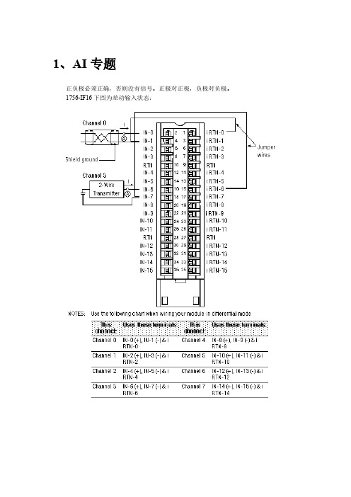
1、AI专题
正负极必须正确,否则没有信号。
正极对正极,负极对负极。
1756-IF16下图为差动输入状态:
上图为单端输入,正负极接错,上位机没有数,首先看24V电源是否正常,即802PX 某个保险端子是否推入,保险是否损坏,然后看+级与—级是否接反(反接一下是否有数),拆下机柜内线用信号发生器发信号(看是否是PLC机柜问题)。
最后到现场拆下线,机柜内部线也拆下来,现场短接,用万用表在机柜端测电阻(校线看是否线用错了)
2、AO专题
AB的PLC板卡接线方式。
1756-OF4模拟量输出模块
模块显示是否有输入,查看24v电源是否送上。
然后用短接线发假信号,端子排上相应端子的保险端子是否正常。
4、DO专题
24V电源直接进入DO输出板子的公共端,如果DO输出亮灯,但是在输出点没有24v 就要量DO板子的公共24v进线是否有电。
查看板子上部灯是否亮,亮说明有输出,在一次
端子用万用表测电压应该为24V。
如果没有,查看PX端子排电源端子是否正常。
1756-OB32
1756-OW16I
1756-OW16I数字量输出模块
左边为24V接入,右侧为输出,如果左侧24V没供电,右侧即使指示灯亮了,也不会有输出。
5、RTD模块1756-IR6I铂电阻模块。
MV156-MCMR通讯模块在泵站监控系统的应用
gv n ie 。whc ssMVI 6 MCM R mo uet e lz db smatrn de Th x ein ei h ed a piain sf  ̄l u ih u e 5一 d l oraieMo u se o . ee p re c n tef l p lcto si n ys mmaie . i i rzd
,n ’
Bo k ,其 通讯 对 象 包括 :1 lc ) )变 电所通 讯 机 ;2 )
占
7只智 能 电 量变 送 器 ;3 )5台超 声 波 流 量 计 ;4 )
1 2台电磁 流量 计 。 MV 5 I6系 列 模 块 是 Mo b s网 络 和 A l — du ln e
21泵 站 Mo b s通 讯 的 系统 结构 . du
包 括 :MV 5 一 M、MVI6 MC I6 MC 5 一 MR 和 MV 5 E I6 — MC M。MV 5 I6的特 性包括 : ( )2个 Mo b s 讯 端 口 ( . 5连 接 器 ) 1 du 通 RI 4 , 支持 R 2 24 24 5连 接 .可设 置为 2个 独立 网络 S 3 /2 /8 的主 节点 或者 从节 点 :
自 动 化
关键 词 :Mob s协 议 ;MV 模 块 ;可 编 程 序 控 制器 (L ;主 站 du I P C)
中 图 分 类 号 :T 2 3 P 7
文 献标 识 码 :A
文章 编 号 :10 — 4 2(0 1 1 0 3— 5 0 9 9 9 2 1)1- 0 2 0
Th p i a i n o VI 6 M CM R o u ei h o io i g a d eAp l t fM c o 5一 M d l n t e M n t rn n
如何使用PROSOFT公司的MVI56-MNET卡件
如何使用PROSOFT 公司的MVI56_MNET 模块1 ControlLogix 架构Modbus TCP/IP 通讯模块1.1 模块简介● 单槽模块,和1756背板完全兼容 ● 在处理器和模块之间进行数据交换时,模块充当一个普通的IO 模块● 通过梯形图实现模块和处理器的数据交换(样例程序已经做好,V16版本以上可使用Add‐On 指令。
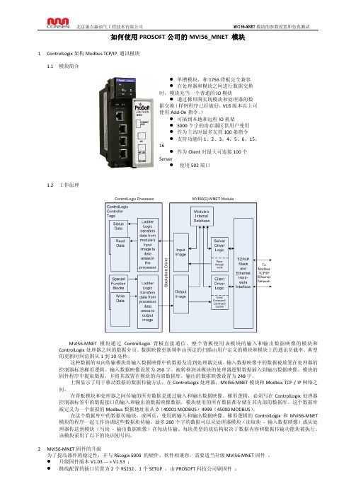
)● 可插到本地和远程IO 机架● 5000个字的寄存器区供用户使用 ● 作为主站时最多支持100条指令 ● 支持功能码1、2、3、4、5、6、15、16● 作为Client 时最大可连接100个 Server● 使用502端口1.2 工作原理MVI56‐MNET 模块通过ControlLogix 背板直接通信。
整个背板使用该模块的输入和输出数据映像的模块和ControlLogix 处理器之间的数据分页。
数据映像更新频率由预定的扫描由用户定义的模块和模块上的通讯负载率。
典型的更新时间范围从1到10毫秒。
这种数据的双向传输模块将输入数据映像中的数据发送到处理器完成。
输入数据映像中的数据被放置在处理器的控制器标签梯形逻辑。
输入数据映像设置为250字。
被转移到该模块的处理器逻辑数据插入到输出数据映像。
模块的固件程序中提取数据,并将其放置在模块的内部数据库。
输出的数据映像设置为248字。
上图显示了用于移动数据的数据传输方法,在ControlLogix 处理器,MVI56‐MNET 模块和Modbus TCP / IP 网络之间。
在背板模块和处理器之间传输的所有数据是通过输入和输出数据映像。
梯形逻辑,必须写在ControlLogix 处理器控制器标签中的数据接口的输入和输出的数据映像数据。
模块使用的所有数据都存储在其内部的数据库。
这个数据库被定义为一个虚拟的Modbus 数据地址表从0(40001 MODBUS )4999(45000 MODBUS )。
在这个数据库中的数据传输块,或网页,使用的输入和输出数据映像。
天信TBQZ、苍南LWQZ涡轮流量计与PLC的MODBUS通讯指南

最近,一个偶然的机会,接到了一个调试流量计的活,目标是两台涡轮流量计,一台天信的TBQZ,另一台是苍南的LWQZ。
这两种表,对于我来说都不陌生,经常在一些天然气的场站里见到,而且两年前还亲手做过这两种表和s7200的通讯。
当时给我的感觉就是挺费劲的(清楚记得带电接了一台天信的表,24v+刚插入端子,眼看着主板就冒烟了,幸而现地显示还正常,通信是没法做了,-_-!),由于当时第一次接触类似的流量计,光研究怎么设置和能不能通讯的问题,就用了一两天,打了很多电话,流量计后盖拆到手软(螺丝很多,注:需要4个的内六角)。
好不容易数据上来了,却是一堆45CAH之类的数(当时真的很菜)。
你承诺的担架呢?浮点数呢!?还得自己计算?呵呵就这样在原计划第二天就要返回400公里以外的家乡上班的情况下,我又坐了回去,(题外话:简直没有办法集中精神,这个旅馆的隔音效果太差,隔壁好销魂)点开那些看了就想骂人的说明书和协议(其实现在想想还好,至少是中文的),又用了一天,终于完成。
所以,这次来之前我是很有信心的,想着一天搞定的,可事实是又用了两天。
究其原因,主要还是很多细节忘了。
为保证这样问题尽可能不再发生,我决定还是写点什么,记录一下。
如能偶然帮到某位同行,缩短他与家人离别的时日,鄙人甚感欣慰。
以上皆属废话,可以不看,重点在下面。
本次调试是基于AB1756冗余系统的,MODBUS模块是PROSOFT的MVI56-MCMPLC方面的问题不是本次重点,我会另外写一篇与大家分享,在此不做赘述。
有问题的话可以把右上角的16进制数转成10进制,大家一起讨论。
天信TBQZ设置:INC+SET密码:0168(按的不正确也会进入某个页面)改nod地址rec 历史记录改为5即modbus-rtu96008n1命令:起始地址2长度11功能码3内部地址:总量40002~40004标况瞬时40005~40006工况瞬时40007~40008温度4000940010压力40011~40012解码:1、把读上来的每个字节按16进制显示2、把40001~40011每个字节用BCD命令转成10进制数(转换后10进制显示应与步骤1的显示数值相等)存在一个数组里,如INT[0]~INT[10]3、分别运算总量=INT[0]*1000000+INT[1]*100+INT[2]/100标况瞬时=INT[3]*100+INT[4]/100工况瞬时=INT[5]*100+INT[6]/100If INT[7]=0THEN温度=INT[8]/100ELSE温度=-INT[8]/100压力=INT[9]*100+INT[10]/100实例:rec历史记录改为4交换浮点数40004总量40006标瞬40008工瞬40010温度40012压力苍南LWQZ设置:SET密码:8888(从右到左4位)SET改COD为0(无校验)改CDR (从站地址)即modbus-rtu96008n1命令:起始地址5长度12功能码3内部地址:总量40005~40008工况瞬时40009~40010标况瞬时40011~40012温度40013~40014压力40015~40016解码:1、把读上来的每个字节存在一个数组里,如INT[0]~INT[11]3、分别运算总量=INT[1]*65536+INT[2]+INT[3]/65536工况瞬时=INT[4]*255+INT[5]/255标况瞬时=INT[6]*255+INT[7]/255温度=INT[9]/255压力=INT[10]*255+INT[11]/255实例:总量:121+19502/65536=121.29757标况瞬时:0工况瞬时:0温度:9298/255=36.46压力:10*255+9478=2587.1686。
ABPLC系统1756模块接线状态说明学习资料
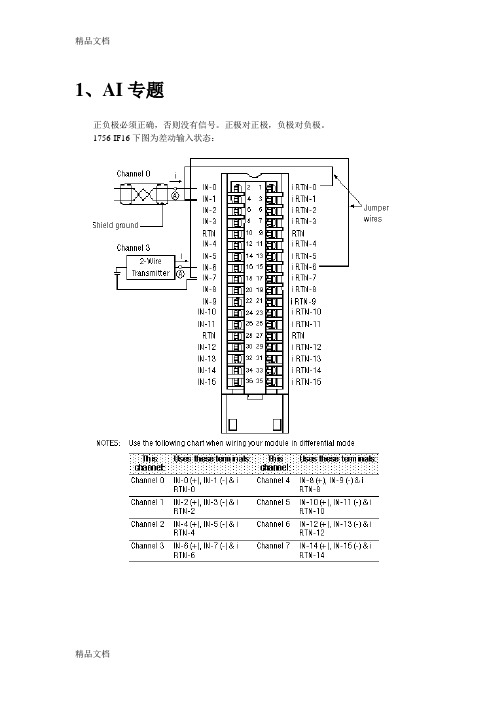
1、AI专题正负极必须正确,否则没有信号。
正极对正极,负极对负极。
1756-IF16下图为差动输入状态:上图为单端输入,正负极接错,上位机没有数,首先看24V电源是否正常,即802PX 某个保险端子是否推入,保险是否损坏,然后看+级与—级是否接反(反接一下是否有数),拆下机柜内线用信号发生器发信号(看是否是PLC机柜问题)。
最后到现场拆下线,机柜内部线也拆下来,现场短接,用万用表在机柜端测电阻(校线看是否线用错了)2、AO专题AB的PLC板卡接线方式。
1756-OF4模拟量输出模块3、DI专题1756-IB32模块1、OK指示灯指示灯状态模板状态描述绿正常正常状态,可以支持多点传送。
绿闪烁异常模板通过了内部检测,但没有多点输入。
红异常需更换模板红闪烁异常上一次通讯超时2、I/O指示灯指示灯状态模板状态描述黄正常激活输入此模块为数字量输入模块,其特性如下图:看PLC模块显示是否有输入,查看24v电源是否送上。
然后用短接线发假信号,查看PX端子排上相应端子的保险端子是否正常。
4、DO专题24V电源直接进入DO输出板子的公共端,如果DO输出亮灯,但是在输出点没有24v 就要量DO板子的公共24v进线是否有电。
查看板子上部灯是否亮,亮说明有输出,在一次端子用万用表测电压应该为24V。
如果没有,查看PX端子排电源端子是否正常。
1756-OB321756-OW16I1756-OW16I数字量输出模块左边为24V接入,右侧为输出,如果左侧24V没供电,右侧即使指示灯亮了,也不会有输出。
5、RTD模块1756-IR6I铂电阻模块6、计数器模块1756-HSC高速脉冲记数模块1756-HSC模块应用下面状态知识LED灯7、第三方通讯模块1756-MVI56MCM MODBUS通讯模块1756-MVI56MCM模块指示灯显示模块运行状态如下:8、以太网通讯模块1756-ENBT 以太网模板精品文档精品文档。
MVI56-MCM ControlLogix 平台 Modbus通讯模块用户手册(中文)

用户手册
August 2003
请阅读以下注意事项 成功的应用这个模块需要对 Allen-Bradley PLC/SLC 硬件知识和现场应用方式有充分的了解。因 此,对于负责完成应用的工作人员,了解应用需求并确保人员和设备不处于不安全或不适当的工作 环境是非常重要的。 这本手册是用作帮助用户。我们力求提供的每个信息都是准确的,而且如实的反映产品的安装要 求。为确保对本产品操作的完全理解,用户必须阅读有关 A-B 硬件操作的所有 Allen-Bradley 应用 文档。 在任何条件下,ProSoft Technology, Inc.都不负责间接的或由用户使用或应用本产品而造成的损 害。 在没有得到 ProSoft Technology 许可的情况下,禁止任何对本手册内容整体或部分性的复制。 本手册内容如有更改,恕不通知。ProSoft Technology, Inc.并不承担这个义务。并会随时改进和/ 或更改此文档或产品。这些更改会阶段性的进行,以更改技术的不准确和印刷排版错误。
MVI56-MCM
/downloads.cfm
产品供货
其它的 MVI56 系列的产品还有:
MVI56-MBP: Modbus Plus 通讯模块 MVI56-ADM: 应用程序开发模块 MVI56-MNET: Modbus TCP/IP 以太网通讯模块
外形
ControlLogix 外形-单槽 连接:
• 2 – RJ45 连接头支持 RS-232, RS-422, 或 RS-485 接口 • 1 – RJ45 RS-232 设置工具连接器
ControlLogix 接口
通过简单的梯形图实现模块运作 使用 RSLogix 5000 软件可以完全实现对模块的设置和监视 通过 I/O 实现 ControlLogix 背板连接 所有模块相关数据都包含在一个处理器数据对象中,这便于配置,监视和连接模块参数. 模块的配置和通讯配置数据通过一个预先在处理器定义的用户数据类型,传送到 MVI56-
设置连接器:
RJ45 RS-232 连接器 (随包装附带 RJ45 到 DB9 的电
缆)
指示灯状态 o 电池状态 o 模块状态 o 端口接收/发送活动(每个端口一个) o 背板活动状态
内置 Intel 80386 处理器 模块和放置在 ControlLogix 槽架内的任何位置
文档
MVI56-MCM ControlLogix 平台
Modbus 通讯模块
产品描述
MVI56-MCM (“Modbus 通讯模块”) 使 Allen-Bradley ControlLogix 处理器轻松的和其它 Modbus 协 议兼容设备连接起来。兼容的设备不仅仅包括 Modicon PLC's (所有型号都支持 Modbus 协议),同 时还包括很大一类的终端设备。
PLC硬件和软件介绍

第一节硬件和软件介绍一、根据实验室模板熟悉AB公司PLC各系列模块1)PLC5大型(实验室无此硬件)2)SLC5003)LOGIX系列CompactLogixFlexLogixControlLogixDriveLogixSoftLogix个人主页给发消息加4)POINT I/O,远程分站I/O.内容:1) 查看各模块的外形,通讯模块,I/O模块,处理器模块等。
2) ControlLogix框架式设计可靠,安装容易,无需工具。
端子可取下,接线方便,更换快速。
主要以此系列PLC作为培训内容3) 可带电热插拔。
安装方便。
4) 有多种网络通讯模块二、配套软件名称1)通讯平台软件:RSLinx;2)Logix系列PLC编程软件:RSLogix5000;3)网络规划软件(控制网):RSNetWorx for ControlNet;4)网络规划软件(以太网):RSNetWorx for EtherNet-IP;5)网络规划软件(设备网):RSNetWorx for DeviceNet;6)上位机软件:RSView32;7)PenelViewPlus触摸屏软件:RSView Studio for SE(ME);三、硬件和软件的版本(见表)表一、软件版本号表二、CPU硬件版本号个人主页给发消息加1、对于硬件主要考虑CPU和通讯模块的硬件版本号。
2、对于各种应用的软件也均存在版本号。
3、在调试时安装软件时要注意各种软件间的版本号匹配。
4、软件安装完后,进行硬件版本刷新,并与软件匹配。
(方法见后续实验)第二节通讯实验如何实现编程器与CPU联机通讯?两个机架通过同轴电缆连接Controlnet模块连接。
在联机前我们要启动Rslinx软件。
对于电脑与PLC联机方式有三种一、使用RS232电缆,将CPU与电脑的COM联接,按下面步骤操作。
1)打开RSLinx,点击或。
2)在工具条上点击3)选择RS-232 DF1 devices4、点击Add New,OK确认。
MCMR配置方法
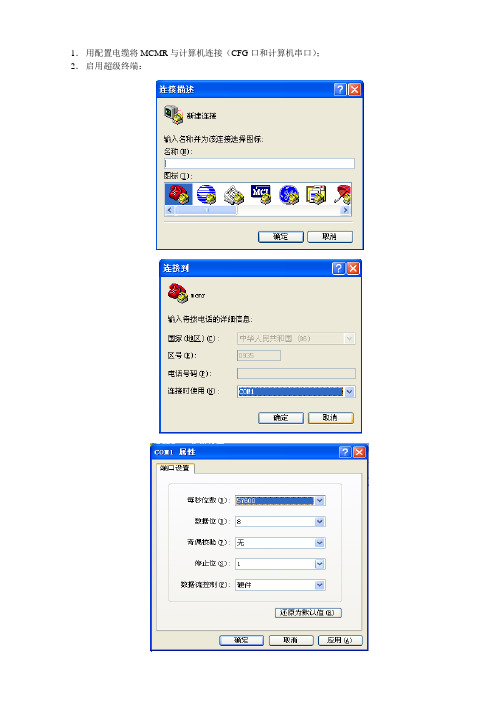
1.用配置电缆将MCMR与计算机连接(CFG口和计算机串口);2.启用超级终端:3.连接正确,超级终端设置完成后,按“?”键,会出现如下屏幕(主菜单):4.下载配置文件:出现上述菜单之后,按“R”键下载配置文件,弹出对话框按“Y”键。
通过超级终端的“传送”发送配置文件(配置文件只能是mcmr.cfg)。
点击“发送文件”,出现如下对话框:“浏览”选择MCMR配置文件,“协议”选择“Zmodem”,之后点“发送”下载配置文件。
5.分析端口数据(Data Analyzer)在主菜单窗口,按“A”键出现如下菜单:按相应的键选择要分析的MCMR的端口(Port 1或Port 2)、数据的格式(Hex或ASCII)。
之后按“B”键开始数据分析,出现如下数据:其中“[ ]”封装的为该端口收到的数据,“< >”封装的为该端口发送的数据。
按“S”键停止数据分析。
注:按“M”键来显示主菜单;按“?”键显示菜单的内容。
注意:在主菜单下不要按“Esc”,否则MCMR会退出应用程序附:MCMR配置文件(鄯善站,端口1和味而达之间的通信,暂时没有调通;端口2设置为和UPS间通信)# MVI56MCM.CFG## Example file for use with the MVI56-MCMR communication module with a# Modbus Master port on PRT2.## DATE : 04/19/2002# LOCATION : Example shipped with MVI56-MCMR communication module# DESCRIPTION : MVI56-MCMR Master# MODIFIED :[Backplane Configuration]# Settings required by both Master and SlaveModule Name : MVI56-MCMR Modbus Master ModuleError/Status Block Pointer : -1 #Offset in virtual database to the start#of the module status listRead Register Start : 0 #Starting register in virtual database to#write to processorRead Register Count : 600 #Number of registers to write to processorWrite Register Start : 600 #Starting register in virtual database to#read from processorWrite Register Count : 600 #Number of registers to read from processorBackplane Fail Count : 10 #Number of consecutive backplane transfer#failures before halting communications#This is an example of a Master port using Modbus RTU protocol[Modbus Port 1]# Settings required by both Master and SlaveEnabled : Yes #Port enable flag Y=Yes, N=NoType : 0 #Port type 0=Master, 1=Slave, 3=Slave Formatted Pass-Through Swapped,#4=Slave Formatted Pass-ThroughFloat Flag : NO #Use floating data type Y=Yes, N=NoFloat Start : 7000 #Register offset in message for floatsFloat Offset : 2000 #Internal Address for floatsProtocol : 1 #Modbus Protocol 0=RTU, 1=ASCIIBaud Rate : 96 #Baud rate for portParity : 0 #0=None,1=Odd,2=EvenData Bits : 8 #5 to 8 data bits for messagesStop Bits : 1 #1 or 2 stop bits for messagesRTS On : 0 #Delay after RTS set before message sent (mSec)RTS Off : 0 #Delay after message before RTS dropped(mSec) Minimum Response Delay : 1 #Number of mSec to delay before resposeUse CTS Line : No #Monitor CTS modem line (Y/N)Response Timeout : 1000 #mSec for response timeout of commandRetry Count : 2 #retry count for failed requests# Settings required for Slave DriverInternal Slave ID : 1 #Modbus Node address for this port on networkBit Input Offset : 0 #Internal DB offset to bit input dataWord Input Offset : 0 #Internal DB offset to word input dataOutput Offset : 0 #Internal DB offset to bit output dataHolding Register Offset : 0 #Internal DB offset to holding reg dataUse Guard Band Timer : No #Use packet gap timeout for messagesGuard Band Timeout : 0 #0=Use default for baudrate, or set timeout# Settings required for Master DriverCommand Count : 2 #Command list count for portMinimum Command Delay : 0 #mSec delay between commandsCommand Error Pointer :200 #Internal database location of cmd err list dataError Delay Counter : 0 #0-65535 Command cycle count if error[Modbus Port 1 Commands]# Internal Poll Reg Swap Node Modbus MB Address# Enable Address Interval Count Code Address Func in DeviceSTART1 1502 2 0 13 329321 1702 2 0 13 33188END#This is an example of a Master port using Modbus RTU protocol[Modbus Port 2]# Settings required by both Master and SlaveEnabled : Yes #Port enable flag Y=Yes, N=NoType : 0 #Port type 0=Master, 1=Slave, 3=Slave Formatted Pass-Through#Swapped, #4=Slave Formatted Pass-ThroughFloat Flag : No #Use floating data type Y=Yes, N=NoFloat Start : 7000 #Register offset in message for floatsFloat Offset : 2000 #Internal Address for floatsProtocol : 0 #Modbus Protocol 0=RTU, 1=ASCIIBaud Rate : 9600 #Baud rate for portParity : 0 #0=None,1=Odd,2=EvenData Bits : 8 #7 or 8 data bits for messagesStop Bits : 1 #1 or 2 stop bits for messagesRTS On : 0 #Delay after RTS set before message sent (mSec)RTS Off : 0 #Delay after message before RTS dropped(mSec)Minimum Response Delay : 1 #Number of mSec to delay before resposeUse CTS Line : No #Monitor CTS modem line (Y/N)Response Timeout : 1000 #mSec for response timeout of commandRetry Count : 2 #retry count for failed requests# Settings required for Slave DriverInternal Slave ID : 1 #Modbus Node address for this port on network Bit Input Offset : 0 #Internal DB offset to bit input dataWord Input Offset : 0 #Internal DB offset to word input dataOutput Offset : 0 #Internal DB offset to bit output dataHolding Register Offset : 0 #Internal DB offset to holding reg dataUse Guard Band Timer : No #Use packet gap timeout for messages Guard Band Timeout : 0 #0=Use default for baudrate, or set timeout# Settings required for Master DriverCommand Count : 2 #Command list count for portMinimum Command Delay : 0 #mSec delay between commands Command Error Pointer :200 #Internal database location of cmd err list data Error Delay Counter : 100 #0-65535 Command cycle count if error[Modbus Port 2 Commands]# Internal Poll Reg Swap Node Modbus MB Address # Enable Address Interval Count Code Address Func in Device START1 02 4 0 13 41601 602 48 0 13 4192 END。
