35-曲烟施设总说明书
艾迪克斯 35 型号 RV 型 CO 丙烷气体报警器 用户手册说明书

RECREATIONAL VEHICLE (RV) Combination Carbon Monoxide and Gas AlarmUSER’S MANUALModel 35-741, 35-742PATENT US 7,248,156 ALL RIGHTS RESERVED 35RV052008-4 ATTENTION:This user’s manual contains important Carbon Monoxide (CO) and gas alarm installation, operation, troubleshooting and warranty information. Read, follow, and keep this manual for future reference.NOTE: If you install or purchase this alarm for another person, give this manual to that person.DUAL SENSOR TECHNOLOGYThe SAFE-T-ALERT™ 35 Series combination CO / Gas Alarm is an alarm that combines into a single compact system, a powerful alarm that detects both Carbon Monoxide (CO) and explosive Propane (LPG)gas. The 35 Series uses the latest microprocessor technology combined with two electronic self-cleaning sensors that operate independently of each other. The combined unit can detect both CO and explosive gases simultaneously.This detector is UL Listed as a CO and Propane gas detector for RV use. Other explosive gases detected, but not tested by UL, include Acetone, Alcohol, Butane, and Gasoline all of which you may have in your RV.To prevent false alarms from brief “puffs” of gas the detector has a recheck cycle before alarming. If high levels of gas remain during the recheck cycle, the detector will alarm.The electronic CO sensor in your SAFE-T-ALERT TM CO alarm is very sensitive to CO gas. It will not react to safe levels of most other gases.WHY EVERY RV NEEDS A 35 SERIES CO AND GAS ALARM Everyone is at risk for carbon monoxide poisoning! Particularly sensitive are children, pregnant women, the elderly and people with lung or heart disease or anemia! Carbon monoxide (CO) is an odorless, colorless gas that prevents the blood from carrying oxygen to vital organs.CO is 200 times more likely to replace oxygen in the blood. The Consumer Product Safety Commission (CPSC) recommends using at least one CO alarm located outside of sleeping areas. For the best security, locate a CO alarm in each sleeping area. Safe-T-Alert CO alarms are available for secondary installations. Propane gas can cause explosions! Using propane requires taking safety precautions to avoid injury. LP gas is usually identified by an unpleasant odor. Certain conditions may make some people unable to detect this unpleasant odor. These conditions include advanced age, colds, allergies, and the use of tobacco, alcohol or drugs that may diminish the sense of smell.ABOUT THIS ALARMBecause CO is a colorless, odorless, tasteless and highly poisonous gas; it can endanger lives even at low levels of concentration. The CO Alarm will alert you to potentially dangerous situations. The following symptoms may be related to CO POISONING. Discuss these symptoms with ALL household members and RV guests:NOTE: Reported cases of CO gas poisoning indicate that whilevictims are aware they are not well, they are disoriented. They are unableto save themselves by exiting the RV or calling for assistance. Small children and pets may be affected first.Your SAFE-T-ALERT TM35 Series alarm helps protect your householdmembers and guests from CO produced while using your RV.CO gas isproduced when any type of fuel is incompletely burned. Potential sourcesof CO in and around your RV can include gas or diesel engine exhaust,portable space heaters, gas stoves and ovens, furnaces, defective engineexhaust systems, portable grills, other nearby RVs, portable generators,generator exhaust, and other propane-powered appliances. All are sources of CO.The following are also sources of CO that may affect your RV:∙Extended operation of unvented fuel burning appliances can build up high CO levels.∙An idling vehicle in an open or closed garage.∙Temperature inversions can trap exhaust near the ground.∙CO build up can be caused by reverse/negative venting of fuel burning appliances including; 1) Clogged, loose or faulty stacks or chimneys of(clothes dryers, furnaces and water heaters, etc.), 2) wind directionand/or velocity, 3) simultaneous operation of multiple fuel burningappliances, and/or exhaust fans.!WARNING:LIMITATIONS OF CO and GAS ALARMSTHIS ALARM WILL NOT WORK WITHOUT POWER.Somereasons for no alarm power are; a blown or missing fuse, broken wire, a faulty wire connection or circuit breaker, a discharged battery, cut lead wires, or improper supply (+) or ground (-) connections.THIS ALARM WILL ONLY INDICATE THE PRESENCE OF GAS AT THE SENSOR. CO or explosive propane/ gas gases may be present in other areas.MTI recommends installing CO alarms in all sleeping areas.Do not block or cover the alarm with any object that can prevent a gas leak orcarbon monoxide from reaching the sensor.THIS ALARM IS INTENDED FOR USE IN RV's. It is intended for use in inside locations of a RV. It is not designed to measure compliance with commercial and industrial standards.THIS ALARM MAY NOT BE HEARD. The alarm’s loudness is designed to meet or exceed regulatory standards; however, the alarm maynot be heard if alarms are located in remote locations or behind closed doors. Persons who are hard-of-hearing, have consumed alcoholic beverages, taken prescription, non-prescription or illegal drugs, may not hear the alarm.THIS ALARM IS DESIGNED TO DETECT CARBON MONOXIDE AND PROPANE GAS. THE ALARM IS NOT DESIGNED TO DETECT SMOKE, OR FIRE.THIS ALARM MAY NOT ALARM AT LOW CO LEVELS - It is not designed to measure compliance with the Occupational Safety Health Administration (OSHA) commercial or industrial standards. Individuals with medical problems may consider using warning devices, which provide audible and visual signals for CO concentrations under 30 ppm.THIS ALARM IS NOT A REPLACEMENT FOR INSURANCE. Always be sure your RV is fully insured.Warning: Installation of the device should not be used as a substitute for proper installation, use, and maintenance of fuel-burning appliances, including appropriate ventilation and exhaust systems.HOW TO PROTECT YOUR FAMILY CAUTION- The SAFE-T-ALERT TM 35 series combination CO and Gas Alarm is designed to protect individuals from the acute effects of carbon monoxide exposure and gas leaks. It will not fully safeguard individuals with specific medical conditions. If in doubt, consult a medical practitioner.To protect your family, you should:∙INSTALL THE ALARM PROPERLY.Carefully read and follow ALL the instructions in this manual. Test your unit every week. Alarms that do not work will not alert you to hazardous levels of CO or explosive gas. See the section, Test Procedure, in this manual for further information.∙MAKE REGULAR VISUAL INSPECTIONS. Check all fuel burning equipment including gas water-heaters, kitchen gas stoves, space heaters, gas dryers and all pilot lights. Check the color of the pilot flame. The color should be blue.∙MAKE REGULAR VISUAL INSPECTIONS OF THE ENGINE AND GENERATOR EXHAUST SYSTEMS. Cracked exhaust systems can allow CO to enter the living area.∙PROFESSIONALLY MAINTAIN YOUR ENGINE AND GENERATOR.Although gas engines and generators produce CO, a poorly tuned engine and generator will produce greater amounts CO.∙If you smell unusual odors you may have a gas leak, immediately call a local propane gas supplier or fire department to check for possible leaks.WHERE TO INSTALL∙Install the 35 series in the kitchen area near sources of a potential gas leaks. Some potential sources are a furnace, refrigerator, stove or oven.If potential sources of a gas leak are in separate areas, MTI recommends installing a gas alarm in each area.∙The Consumer Product Safety Commission recommends installinga CO alarm outside the sleeping area. The 35 series combinationCO and gas alarm complies with that recommendation.∙INSTALL ALARM at least 4 inches but not more than 20 inches off the floor.WHERE NOT TO INSTALL 35 SERIES ALARMS∙DO NOT INSTALL behind furniture, drapes, in closets or areas that will block gas flow to the alarm.∙DO NOT INSTALL within 12 inches (30cm) of opening windows, exterior doors, heating or return vents, or other drafty areas.∙DO NOT INSTALL on an outside wall.∙DO NOT INSTALL on a wall switch controlled by a power line, ground fault circuit or to a circuit breaker.∙NOTE: Older RVs may have little or no insulation and therefore are draftier. Carefully consider mounting locations.The following diagrams provide additional alarm installation information:INSTALLATION INSTRUCTIONSModel 35-741, 35-742!WARNINGFAILURE TO FOLLOW THESE INSTRUCTIONS MAY RESULT IN A MALFUNCTION OR FAILURE OF THE ALARM AND MAY VOID THE WARRANTY.SHOCK HAZARD: Turn off power before installing.Power Supply 12 VDC.Recommended Wire Size 14 GA. TO 18 GA.Connect the alarm to a properly fused circuit, maximum over protection device rating 15 amps.SPECIAL WIRING NOTICE: When replacing CCI Controls LP Gas Leak Detectors they may have two power leads. Safe-T-Alert units have one power lead. Simply connect the Safe-T-Alert power lead (Red) to the coach/house power supply and cap or remove the second power lead. DO NOT CONNECT BOTH POWER LEADS TO THE Safe-T-Alert ALARM – this will result in a dead chassis battery.Do not install within 12" ofa window that can openDo not install within12" of a doorDo not installwithin 12" of ventsDo Not install behinddrapes or furnitureRecommended Alarm LocationRecommended Alarm LocationDO NOT INSTALLFigure 3Connect to wiring or circuit that CANNOT be turned off by a switch or ground fault protector. Only use UL or recognized permanent wire connectors. It is acceptable to connect the 35 Series CO / LP gas alarm to the main disconnect. The alarm will be off along with all other 12 volt equipment when the main disconnect is turned to the off position. The RV must not be occupied when the main disconnect is in the off position.INSTALLATION INSTRUCTIONSFollow these instructions carefully. Failure to follow these instructions can damage the unit and void the warranty.Select a wall location at least 4” but not more than 20” off the floor.1.Disconnect the power supply being connected to.2.Model 35-741 requires a 1/2” hole be drilled where mounting.Model 35-742 requires a 1” clearance to recess the case. Cut a5 3/8” W x 2” H hole3.C onnect the RED (+) power lead to the fused circuit. Connectthe BLACK lead to Ground (-).4.Fasten the unit to the wall using the two screw holes located onthe ends of the case5.Reconnect the power supply. Wait 10 minutes for warm up andthen test the alarm.NOTE: All connections must be in accordance with the National Electrical Code in the Unites Stated and the Canadian Electric Code in Canada .TEST PROCEDURE!WARNINGTO REDUCE THE RISK OF CARBON MONOXIDE POISONING OR PROPANE GAS EXPLOSION, TEST THIS ALARM’S OPERATION AFTER THE RV HAS BEEN IN STORAGE, BEFORE EACH TRIP AND AT LEAST ONCE PER WEEK DURING USE.!WARNINGWARNING: THE TEST BUTTON ONLY TESTS THE ALARM CIRCUIT NOT THE SENSORS. YOU MAY USE PROPANE OR BUTANE GAS TO TEST THE GAS SENSOR. Note it may take up to 10 seconds for the alarm to sound.TO TEST THE CO SENSOR USE A CAN OF SAFE-T-ALERT CO TEST GAS TO TEST THE 400 PPM CALABRATION POINT. DO NOT TRY TO GENERATE CO TO TEST THE ALARM. The TEST/RESET button tests all ELECTRICAL functions of the alarm. It does not check the sensor operation.The alarm may be tested at any time -The TEST/Mute switch is located on the front of the alarm Press and hold the test button for 1 second. The alarm is working properly if the GREEN indicator light changes color to RED and the horn beeps 4 times. The Gas LED should also blink Red. IMPORTANT - If this alarm does not test properly return it immediately for repair or replacement.OPERATIONEach time the unit is first powered up, the CO sensor requires a ten (10) minute initial warm-up period to clean the sensor element and achieve stabilization. The GREEN LED indicator will flash on and off during the 10 minute warm-up period. This unit cannot go into a CO alarm during the warm-up period. To test your unit during the warm-up period, press the test button. See Test Procedure in this manual. After the warm-up period, the GREEN power ON indicator should glow continuously If the ON indicator light does not light, see the section, Trouble-Shooting Guide, in this manual for further information. Do not attempt to fix it yourself. Gas Alarm: When you power the alarm, it has a warm-up period of approximately 1 minute. This unit cannot go into a gas alarm during the warm-up period. After 1 minute the alarm can detect explosive gas. Simultaneous CO and Gas Alarms— Because the risk of a propane gas explosion is generally a more serious danger, your alarm unit gives the gas alarm a higher priority during simultaneous alarm condition.If your unit generates alarms for both Gas and CO at the same time, the gas LED will flash red and the beeper will sound. The CO LED will be a solid Red until the CO is ventilated out of the RV, at which time the LED will return to the Green operational/safe color.Brownout Protection - The unit can tolerate short power interruptions and brownouts where the circuit voltage drops as low as 1VDC. If the brownout lasts too long, the unit will reset and operate as described above.LOW POWER OPERATIONThis alarm will operate normally down to7 VDC. Do not operate this alarm below 7 VDC.VISUAL AND AUDIBLE ALARM SIGNALSThis SAFE-T-ALERT TM CO / Propane Gas Alarm is designed to be easy-to-operate. The alarm has two indicator lights that display a specific color for each monitored condition. There also is a matching sound pattern for alarm conditions.CO ALARMThe Red CO LED will flash and the alarm will sound 4 “BEEPS” then silent for 5 Seconds. These signals indicate that the CO level is over 35 ppm. IMMEDIATE ACTION IS REQUIRED. See Procedures To Take During An Alarm. This cycle will continue until the TEST/Mute button on the front of alarm is pressed. Ventilate the RV. The RED light will stay ON until the CO has cleared, or the alarm will reactivate in approximately 6 minutes if the CO is still present. DO NOT RE-ENTER THE RV. This alarm will return to normal operation after the RV s properly ventilated.PROPANE GAS ALARMThe Red LED will Flash and the alarm will sound a steady tone whenever a dangerous level of propane gas is detected. IMMEDIATE ACTION IS REQUIRED. See Procedures Take During A Gas Alarm The detector will continue to alarm until the Test/Mute switch on the front of the alarm is pressed. Ventilate the RV. The RED Gas LED will continue to flash until the gas has cleared, or the gas alarm will reactivate in approximately 5 minutes if the gas is still present. DO NOT RE-ENTER THE RV. This alarm will return to normal operation after the RV s properly ventilated. MALFUNCTION/SERVICE SIGNAL If any malfunction is detected, the Gas LED will remain off and the Operational/CO LED will alternate Red/Green and the alarm will sound once every 15 seconds. Press the Test/Mute button. If the Test/Mute button does not clear the signals, check the battery voltage. I f the battery voltage is not low and the unit will not return to normal operation,immediately remove the alarm and return for service or warranty replacement.See the warranty section in this manual.TROUBLE-SHOOTING GUIDEUse this chart to trouble-shoot problems with this 35 series Alarm. PROBLEM CAUSE/SOLUTIONGreen Operational LED Off 1.Bad Wire Connection2. Reversed Wiring3. Main Power Off4. Missing or Blown FuseNo Sound When Testing Contact Customer ServiceNo Red LED When Testing Contact Customer Service Locked In Alarm Contact Customer Service MALFUNCTION ALARM LED 1. Check Battery VoltageRed/Green & BeepsEvery 15 SecondsBattery Voltage is Good and it 2. Contact Customer ServiceWill Not Reset To Normal operationEND OF LIFE ALARM3 days – Replace within 30 days. Customer Service 800-383-0269 HOW TO TAKE CARE OF YOUR ALARMThis CO / Propane Gas Alarm is designed to be as maintenance free as possible. To keep your alarm in good working order, you must:∙TEST THE ALARM WEEKLY. See the section, Test Procedure, in this manual for further information.∙VACUUM THE DUST OFF THE ALARM COVER. At least once a year (more frequently in dusty locations), use the soft brush attachment of your vacuum to clean the alarm cover.∙CLEAN THE ALARM COVER WHEN DIRTY. Wash the alarm cover by hand. Use a cloth dampened in clean water. Dry with a soft cloth.∙DO NOT SPRAY CLEANING AGENTS OR WAXES DIRECTLY ONTO THE FRONT PANEL. This action may damagePROCEDURES TO TAKE DURING AN CO ALARM Follow the alarm procedures for your country. The emergency number depends on your travel location.End of Life Signal – The Sensor has a 5 Year Service LifeAll 35 Series models include an End of Life (EOL) Signal indicating the sensor has reached the end of its service life and you must replace the alarm. The signal is the LED flashing RED RED GREEN GREEN with a beep every 25-30 seconds. The EOL Signal may be reset by pushing TEST / RESET button on the alarm. This will reset the EOL Signal for a period of 72 hours (3 days) for a total of up to 30 days. After 30 days the signal cannot be reset and the alarm must be replaced. DO NOT DISCONNECT THEALARM UNTIL YOU HAVE A REPLACEMENT ALARM AVAILABLE TO INSTALL.SPECIFICATIONSMODELS 35-741, 35-742POWER SUPPLY 12 VDCNOMINAL CURRENT DRAW 108 mAOPERATIONAL TEMPERATURE -40o F to +150o F -40o C to +66o CRELATIVE HUMIDITY 15% (+/- 5%) to 95% (+/- 4%)AUDIBLE OUTPUT 85 dB @ 10 feetGAS ALARM TRIGGER < 25% of the LEL of PropaneGAS LEVEL CONFIRMATION 8 Second Alarm DelayCO ALARM TRIGGER <15 Minutes @ 400 ppmCASE DIMENSIONS 35-741 6” W x 1.875”H x 1.375”D35-742 6.5”W x 2.75”H x 1.5”DWARRANTY 1 Year LimitedTESTING LABORATORY ETL IntertekSTANDARD UL 1484, Fourth EditionUL 2034, Third EditionCSA 6.19-01OWNERS REPLACEMENT RECORDReplace this SAFE-T-ALERT TM 35 SERIES CO / GAS propane alarm 5 years after date of installation. For new RV’s enter the month and year the RV was manufactured. If you are not sure, enter the month and year you purchased the RV or enter May and the model year of the RV (example May 2014), whichever is the earlier date. Installation Date: ____________________________ (Example: March 2014)Replace by Date _______________ ________________(5 years after Installation date – example: May 2019)If you don’t know the installation date, replace the alarm no later than 5 years after the production date on the back of the alarm.LIMITED PRODUCTS WARRANTYMTI INDUSTRIES, INC. warrants to the original retail purchaser that its products will be free from defects of material or workmanship for a period of One (1) year from the date of retail purchase. If proven to have been defective in original materials or workmanship and returned, delivery costs prepaid, MTI INDUSTRIES, INC. will replace this product free of charge.LIMITS OF WARRANTYReplacement is your exclusive remedy under this limited warranty or any other warranty (including any implied warranty of merchantability for a particular purpose). Any and all implied warranties or merchantability or fitness for a particular purpose shall be limited to the warranty period from the original date of retail purchase. MTI INDUSTRIES, INC., its dealers and distributors shall in no case be responsible or in any way liable for any incidental or consequential damages for any reason. Some states do not allow the limitation or exclusion of incidental or consequential damages, or allow limitations on how long an implied warranty lasts, so the above limitations may not apply to you. This warranty gives you specific rights, and you may also have other rights, which may vary, from state to state.PRODUCT NOT WARRANTEDNOTE-There are no user serviceable parts inside the case. Opening any SAFE-T-ALERT TM product for any reason voids the warranty.This warranty does not cover damage or failure resulting from acts of God, abuse, misuse, neglect, or faulty installation.WARRANTY RETURN PROCEDURESIt is MTI’s experience that a CO / Propane Gas Alarm is sounding f or a reason. Call, ask your dealer to call, or e-mail our Customer Service Department (as listed below) to trouble shoot the situation.Customer Service Phone No. - 800-383-0269Fax No. 847-546-9007*******************************Web Site: If Customer Service determines that the unit is defective, a Return Authorization (RA) number will be issued. No product will be accepted for service or replacement without first obtaining a RA number.If authorized, return this product to:MTI Industries, Inc.Warranty Dept. RA # (INSERT RA NUMBER HERE)31632 N. Ellis Drive Unit 301Volo, IL 60073NOTE: Mark the RA number in the area shown on the outside of the box!NOTE:35 Series is the basic unit with no interconnection and no relay. If you want these features order a custom 70-742 from MTI Industries.© MTI INDUSTRIES, Inc. 2013。
说明书0_DK3520A说明书(大师兄版)
本说明书中凡是带
标志的章节或文字是需要特一章
录
概述.....................................................................................................................................1
1.1 适用范围......................................................................................................................................1 1.2 装置主要功能..............................................................................................................................1 1.2.1 保护功能...............................................................................................................................1 1.2.2 辅助功能...............................................................................................................................1 1.2.3 遥测功能.............................................................
京威公司YJP-Q25 30 35喷射式液体加热器说明书

二、工作原理1.主电机罩、2.助燃风轮、3.主电机、4.联轴器、5.联接体、6.油泵、7.燃烧室、8.热传导片、9.热交换器、10.安装架、11.排烟管、12.喷油嘴、13.点火电极、14.点火线圈 、15.管道泵、16.滤清器、17.进油截止阀、18.回油管加热器由燃烧系统、热交换器、管道循环系统和控制系统四部份组成。
燃烧系统包括燃烧器、燃烧室(9)、点火电极(14)等组成,其中燃烧器由直流电机(3)、助燃风轮(2)、喷油嘴(14)、油泵(8)等组成。
油泵在电机带动下,吸入的燃油经输油管送到喷油嘴(14),靠压力作用被喷油嘴喷出,喷出的高压油雾与助燃风扇吸入的空气在燃烧室(9)内混合,被点火电极(14)点燃,在燃烧室内充分燃烧后,燃气流经热交换器内壁的热传导片(10),通过热传导片把大部分热量传递给热交换器(11)夹层中的水(防冻液)。
液体在管路中靠管道泵(17)强制排出,经管道进入车内布置的自然散热片或强制散热器水箱,再与车内空气进行热交换,达到加热器取暖的目的。
燃烧废气由排烟管(13)排出。
■ 加热器应防止水淋或泥浆溅入,同时要避免积尘、积水以防待运转发动机后(踩油门),直至放气阀尤其是加热器放气阀无六、加热器外形安装尺寸图 024七、加热器接线图KC30-0030KC30-00315八、控制开关操作方法本加热器的操作开关为一支三档翘板开关,与两个指示灯共同组成。
按动一下翘板开关,加热器水泵工作,此时加热器水泵将发动机水箱余热送入车厢散热器中,而加热器不燃烧供热,电源指示灯绿灯(L1)亮,在天气不太冷时或发动机高速运转水温较高时,可采取此种工作方式,此时加热器自动控制板不供电,此种工作方式可以延长加热器电路部分寿命。
当发动机水温低或需预热发动机时,再按一下开关(此时进入II状态),加热器工作,此时状态指示灯绿灯(L2)同时亮热器后关闭电机,当水温再次低于70℃加热器再启动供热,如此往复序号故障代码故障类型20注意:安装京威公司SWV-38型电调阀门的管路,需将散热片管路与除霜器管路(单独铺设)并联,电调阀门必须安装在散热片管路上,保证电调阀门完全关闭后,管路内的循环液仍可以通过除霜管路循环。
阿尔法拉瓦尔LYNX 35分心净化机说明书
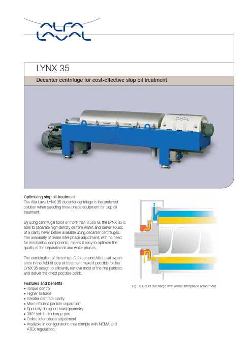
LYNX 35Decanter centrifuge for cost-effective slop oil treatmentOptimizing slop oil treatmentThe Alfa Laval L YNX 35 decanter centrifuge is the preferredsolution when selecting three-phase equipment for slop oiltreatment.By using centrifugal force of more than 3,500 G, the L YNX 35 isable to separate high-density oil from water, and deliver liquidsof a clarity never before available using decanter centrifuges.The availability of online inter-phase adjustment, with no needfor mechanical components, makes it easy to optimize thequality of the separated oil and water phases.The combination of these high G-forces and Alfa Laval experi-ence in the field of slop oil treatment make it possible for theL YNX 35 design to efficiently remove most of the fine particlesand deliver the driest possible solids.Features and benefitsFig. 1: Liquid discharge with online interphase adjustment • Torque control• Higher G-force• Greater centrate clarity• More efficient particle separation• Specially designed bowl geometry• 360°solids discharge port• Online inter-phase adjustment• Available in configurations that comply with NEMA andATEX regulations.Technical dataWater flow*1 – 15 m 3/h (4-66 GPM)Oil flow*1 – 10 m 3/h (4-44 GPM)Solids flow*1 – 5 m 3/h (4-22 GPM)Maximum speed 3,650 rpm Centrifugal force up to 3,574 G Differential speed range 2-40 rpm Solids capacity Up to 12 ton/h (26,000 lbs)Main power 90 kW (125 Hp)Backdrive power 15 kW (20 Hp)Dry weight of decanter unit5,000 kg (11,000 lbs)*Typical values, contact Alfa Laval for details.How to contact Alfa LavalUp-to-date Alfa Laval contact details forall countries are always available on ourwebsite at PEE 00105EN 0508Alfa Laval reserves the right to change specifications without prior notification.Principle of operationThe LYNX 35 is a decanter centrifuge that features a slendercylindrical bowl with a relatively large length/diameter ratio,and a conical end. This bowl rotates at speeds of up to 3650rpm, producing centrifugal force of anywhere from 300 to3574 G. A screw conveyor fitted inside the bowl ensures thecontinuous removal of the separated solids.The feed is led into the bowl through a stationary inlet tubeand then smoothly accelerated by an inlet rotor. Centrifugalforce causes instant sedimentation of these solids on the wallof the bowl. The screw conveyor rotates in the same direction as the bowl, but at a different speed, and thus transports the solid phase of the slop oil to the conical end. These solids are then lifted clear of the liquid, and the capillary liquid is then drained centrifugally, before being discharged into the casing through the solids discharge port.Separation into two liquid phases takes place over the entire length of the cylindrical part of the bowl, and the clarified heavy and light liquid phases are discharged from the bowl by flowing over two sets of level tubes.Max. 5035 mm (198 in)1190 mm (47 in)1325 m m (52 i n )Feed Solids Water Oil GearboxScrew conveyor Wall of the bowlInlet distributorConical end Discharge portFeed tubeCutaway view。
青岛炼化_35_柴油的生产及优化
青岛炼化-35#柴油的生产及优化冯文远,毕晶晶(中国石化青岛炼油化工有限责任公司,山东青岛266500)摘要:根据青岛炼化的生产实际,对比分析各种柴油组分油的性质,找到了适合生产和调合-35#柴油的馏分油。
通过优化装置操作和现场流程改造,实现了-35#柴油的生产,且效益可观。
关键词:-35#柴油蜡含量凝点冷滤点中图分类号:TE626.24文献标识码:B文章编号:1009-9859(2014)01-0051-04中国石化青岛炼油化工有限责任公司(简称青岛炼化)是1个年加工能力12Mt的单系列炼油厂,主要加工中东的高硫、低酸原油。
直馏柴油、减一线馏分油、焦化柴油、催化柴油都是通过加工能力为4.2Mt/a柴油加氢装置精制后直接作为柴油产品出厂。
为满足随季节性变化而变化的市场需求,同时拓宽青岛炼化产品种类,从2009年冬季开始研究生产-35#柴油的方案。
由于青岛炼化柴油的二次加工装置只有柴油加氢,无现成的组分可以直接作为-35#柴油出厂。
因此,选择了通过原料优化、柴油加氢精制,然后再调合的生产方案。
1青岛炼化的柴油产品青岛炼化柴油加氢装置主要的原料是常二线、常三线、减一线馏分油及焦化柴油、催化柴油,通过精制脱除柴油中的硫、氮和重金属等杂质,精制后的柴油产品质量见表1。
表1青岛炼化精制柴油质量ħ性质-35#柴油国Ⅱ质量指标青岛炼化柴油实测值闪点≥4562凝点≤-35-16冷滤点≤-29-12十六烷值≥4043馏程初馏点166.510%217.050%≤300264.590%≤355333.595%≤365357w(硫),%≤0.2000.031由表1可知,青岛炼化柴油凝点-16ħ,冷滤点-12ħ。
其质量指标相对于0#和-10#柴油过剩较多,和-35#柴油国Ⅱ质量指标相差很大。
但从理论上来说,青岛炼化加工国外含蜡量较低的中间基原油是可以生产出-35#低凝点柴油的。
2影响生产-35#柴油的因素分析2.1原油性质(见表2)表2青岛炼化原油性质原料来源沙特(中质油)沙特(重质油)伊朗(重质油)科威特w(蜡),% 3.32 4.24 3.90 2.70原油类别中间基,含蜡中间基,含蜡中间基,含蜡中间基,含蜡如表2所示,青岛炼化加工的都是国外原油,国外原油的主要特点是蜡含量较低,沙特中质油、沙特重质油、伊朗重质油和科威特原油都属于含蜡量较低的中间基原油;蜡含量最高的沙特重质油只有4.24%。
IGEBA TF-35 蒸汽化学喷雾机操作指南说明书

‘How To’Series for the IGEBA TF-35 FoggerThis is an illustrated supplement to the owner’s manual supplied with your fogging machine .For more details refer to the owner’s manual.This illustrated supplement applies to the IGEBA TF 35series,including the TF-35,TF-35/10,TF-W-35and TF-W-35-L fogger models.- Cleaning/Replacing the Diaphragm -Removing the Knurled Nut and Silencer Cap reveals the Air Intake Valve assembly.Remove the 3mounƟng screws that hold the Air Intake Valve assembly to the Mixing Chamber.Nixalite of America Inc -102516th Ave -East Moline,IL 61244-P -******************If your fogger is difficult to start or runs for a short Ɵme then quits,you may need to clean or replace the Diaphragm in the Air Intake Valve Assembly.The following shows where this is and how to clean/replace the Diaphragm.Air Intake Valve assembly Remove 3Screws.Do not lose them!Remove the Gasket from the back of the brass Valve Plate.Replace Gasket if damaged.Take Air Intake Valve apart by removing the assembly screw and nut.Clean and set aside.The Diaphragm is a thin mesh washer between the plasƟc Spacer Plate &brass Valve Plate.Inspect the Diaphragm for any cracks,folds or tears.Replace Diaphragm if damaged.GasketSpacer PlateValve PlateHex Nut Assembly ScrewDiaphragmValve PlateSpacer PlateValve PlateClean and recondiƟon the Valve Plate surfaces with a 240grit sandpaper on a flat surface.If the holes in the Valve Plate are dirty or clogged,clean them by hand with small drill bits.DiaphragmValve Plate240grit sandpaperValve PlateUse 2.9mm drill for outer holes and 2.5mm drill for inner holesInside of Air Valve AssemblyMixing ChamberMORE TIPS &DETAILS:>there’s a spare Diaphragm REMEMBER in the tool kit included with your fogger .Keep this with you so you can quickly install a fresh Diaphragm and get back to fogging.>When puƫng the Air Intake Valve back together,make sure that the Diaphragm stays centered.UnƟl the screw and nut are Ɵght,the Diaphragm can move around.It must be centered over the holes in the brass Valve Plate to run properly.Keep the Diaphragm centered by holding the parts firmly while Ɵghten the assembly screw and nutNixalite of America Inc1025 16th Ave, E. Moline, IL 61244*******************************®Nixalite of America Inc is the US Sales and Service Center for IGEBA EquipmentThis is an illustrated supplement to the owner’s manual supplied with your fogging machine .Always read,understand and follow the safety measures and instrucƟons provided in the manufacturers fogger manual.- Cleaning/Replacing the Diaphragm -Use a soŌclean cloth to clean both sides of the Spacer Plate,Valve Plate and Gasket.The raised hub of the Spacer Plate fits into the depression machined in the Valve Plate.Keep Diaphragm centered over the Valve Plate holes.Reinstall the assembly screw and nut.Place Gasket on the Valve Plate as e a mounƟng screw to help align the gasket.Reinstall the 3mounƟng screws that hold the Air Intake Valve assembly to the Mixing Chamber.Raised Spacer hub of Plate......fits into this depression on the Valve PlateLong Screw and NutGasketUse help align 1screw to gasketReinstall 3ScrewsKnurled NutVIDEOYou can watch /product/igeba-ƞ-35800.624.1189******************。
烤烟品种闽烟35采收适宜成熟度初探
烤烟品种闽烟35采收适宜成熟度初探兰金隆;蓝周焕;赖荣泉;彭国华;高友峰;吴晓凤【摘要】The field trials were carried out to define the appropriate mature degree of flue -cured tobacco variety Minyan 35 for harvest in Shanghang county of Fujian province in 2009. The result showed that the days of 20 d, 50 d, or 65 d after topping were appropriate for the harvest of the upper, middle or lower tobacco leaves, respectively. At the stages of the mature harvest, the leaves of Minyan 35 had more favorable appearance quality, economic characters, chemical composition and the highest score of sensory evaluation. Thus, it suggested that the better yield and quality might be achieved by the mature harvest models for Minyan 35.%为探索烤烟品种闽烟35采收适宜成熟度,于2009年在福建省龙岩上杭烟区采用田间试验,研究了特色烤烟闽烟35品种采收适宜成熟的标准,结果表明:闽烟35下部叶打顶后20 d左右采收,外观质量、成熟度、叶片柔软性及弹性均较好,色度为中,均匀性好,化学成分较协调.中部叶打顶后50 d左右采收,成熟度、叶片柔软性及弹性均好,光泽较鲜艳,色度强,香气质、浓度及余味均较好.上部叶打顶后65 d左右采收的最好,上等烟比例和均价都最高、成熟度较好、组织结构尚疏松、色度较强、香气量足、香气质最好,烟气柔和、余味较舒适.【期刊名称】《江西农业学报》【年(卷),期】2012(024)011【总页数】4页(P100-103)【关键词】烤烟;闽烟35;采收;成熟度【作者】兰金隆;蓝周焕;赖荣泉;彭国华;高友峰;吴晓凤【作者单位】福建省龙岩市烟草公司上杭分公司,福建上杭 364200;福建省龙岩市烟草公司上杭分公司,福建上杭 364200;福建省烟草农业科学研究所,福建福州350003;福建省龙岩市烟草公司上杭分公司,福建上杭 364200;福建省龙岩市烟草公司上杭分公司,福建上杭 364200;福建省龙岩市烟草公司上杭分公司,福建上杭364200【正文语种】中文【中图分类】S5720 引言烤烟是我国重要的经济和出口创汇作物,然而,影响烟叶品质的因素很多,如品种、病虫害等[1-4],严重影响了烟叶的产质量。
YJ35D烟机说明书

一、YJ35D装盘机如图1-2-1所示,YJ35D装盘机主要由卷烟输入装置4、料库6、空盘输入装置1、卷烟装盘装置5、满盘输出装置2、满盘提升装置3和电控系统7等组成。
卷烟输入装置将来自卷接机组的卷烟输送到料库;料库对卷烟起缓存和输送作用;空盘输入装置将空盘依次自动送到装盘设备上,准备装盘;卷烟装盘装置把卷烟均匀、无损伤的装入烟盘中,且保持与卷接机组速度的匹配,直到装满卷烟的烟盘落入满盘输出装置上;满盘输出装置把装满物料的烟盘向后输送;满盘提升装置将满盘输出装置输出的烟盘提升到一定高度,便于人工转运满盘;电控系统通过PLC控制,完成各功能部件动作的协调统一。
图1-2-1YJ35D装盘机结构简图1.空盘输入装置2.满盘输出装置3.满盘提升装置4.卷烟输入装置5.卷烟装盘装置6.料库7.电控系统如图1-2-2所示,YJ35D装盘机启动前,卷烟装盘装置处于装盘截流状态;当空盘输入装置启动,空盘进入卷烟装盘装置烟盘托架时,装盘截流打开,同时整理辊及阻挡杆同步摆动,烟盘托架通过链条驱动慢速下降,开始装盘;之后,拍齐装置启动拍打整理卷烟;当烟盘料位到达预设料位时,装盘截流关闭,烟盘托架下降停止,拍打整理停止,装盘停止;烟盘托架实现快速下降、减速下降到停止位置,此时,位于卷烟装盘装置下的一对烟盘托架运行到位;空盘输入装置启动,第二次装盘开始。
同时,在装盘过程中,烟盘托架慢速下降,装满卷烟的满盘落到满盘输出装置上;当检测开关检测到满盘输出装置满盘区有满盘时,满盘输出装置启动,满盘输出,完成一个工作循环。
图1-2-2装盘机工作流程图YJ35D装盘机具有新世纪机电产品的共同特点,即速度高、自动化程度高,同时又吸收了同类产品的优点,克服了同类产品的不足,是一种集机、电为一体的较为完善的高速装盘设备。
该机具有如下主要特点:(1)输送质量好。
采用了单排卷烟装盘和曲柄滑块机构及四连杆机构实现空盘进给等先进的原理,保证了在空盘进给、装盘、截流、拍齐等过程中,动作轻柔,稳定可靠,不易产生乱烟和横烟,卷烟输送平稳。
35t燃气锅炉操作规程
操作规程第一章:概述1.SZS35-1.25-Y、Q(LN)型燃气蒸汽锅炉采用双锅筒、纵置式、D型布置的自然循环型结构。
该锅炉设计的额定蒸发量为每小时35吨,194℃的饱和蒸汽,由锅炉主蒸汽出口接出。
2. 锅炉采用微正压的燃烧方式,鼓风机随燃烧器配套。
3. 锅炉主体组装出厂。
锅炉主机由上下锅筒、膜式水冷壁、对流管束、钢架、护板、保温层等组成。
4. 锅炉上下锅筒筒体拼接采用全自动焊拼接,焊缝进行100%射线探伤。
5. 锅炉右部为炉膛,其四周均以膜式水冷壁包围,受热面及燃烧空间充裕。
对流管束设置在锅炉左部,四周亦以膜式壁结构完全密封,对流管书采用顺列式单回程布置,受热面积大,烟气流速设计合理,最大程度上优化了锅炉对流区域的传热。
6. 为降低排烟温度提高节能效果,锅炉尾部配置有节能器和冷凝器。
7. 燃料在右侧炉膛内燃烧,与炉膛四周水冷壁进行辐射换热后,产生的高温烟气经锅炉后部炉膛出口进入锅炉左侧对流管束区域,冲刷对流管束进行对流换热,再进入尾部节能器和冷凝器,最终以较低的温度经烟囱排入大气。
8. 锅炉后墙设有观火孔、炉膛出口的烟温测点和炉膛压力测点。
为确保安全,在锅炉顶部设置了防爆门。
9. 保温层主要为硅酸铝纤维,其具有保温性能好、重量轻的优点。
锅炉外护板采用自攻螺钉固定的可拆卸的压制成型护板。
10. 锅炉燃烧装置根据用户使用的燃料选配,详见随机提供的说明书。
11. 该锅炉的自控系统采用可编程序控制,具备较完善的控制功能,包括:给水自动控制、燃烧的自动调节、蒸汽超压保护、气压高低保护、检漏、前后吹扫、熄火保护以及相应的联锁及安全保护等。
详见自控说明书。
锅炉的主要规范:第二章:锅炉的运行工艺流程简介:一:水处理1.水质的好坏会影响锅炉的热效率和使用寿命,搞好锅炉水处理是保证锅炉安全经济运行的重要环节之一。
未经处理的水硬度高,含有固体微粒及溶解气体,容易引起结垢、腐蚀等。
2.我单位采用离子交换树脂对原水进行软化处理。
- 1、下载文档前请自行甄别文档内容的完整性,平台不提供额外的编辑、内容补充、找答案等附加服务。
- 2、"仅部分预览"的文档,不可在线预览部分如存在完整性等问题,可反馈申请退款(可完整预览的文档不适用该条件!)。
- 3、如文档侵犯您的权益,请联系客服反馈,我们会尽快为您处理(人工客服工作时间:9:00-18:30)。
编号:QY-XS-A0101-01曲靖市35kV曲烟规划区段线路迁改工程施工图设计第一卷第一册总说明书曲靖供电有限责任公司电力工程设计所2009年11月批准:审核:校核:编制:施工图设计总目录第一卷总说明书、设备材料汇总表及附图、第一册总说明书及附图1. 总说明书 QY-XS-A0101-012. 曲烟规划区线路走向平面图 QY-XS-A0101-023. 杆塔型式一览图 QY-XS-A0101-034. 基础型式一览图 QY-XS-A0101-045. 导线(LGJ-185/25)、地线(GJX-50)力学特性表 QY-XS-A0101-05 第二册设备材料汇总表 QY-XS-A0102第二卷路径平断面定位图及杆塔明细表1. 线路纵断面图 QY-XS-A02012. 杆塔明细表 QY-XS-A0202第三卷机电施工图第一册机电施工图1.导线、地线安装表 QY-XS-D0301-012.电缆与架空线连接图 QY-XS-D0301-023.单联悬垂绝缘子串组装图 JD-0401P4.单联耐张绝缘子串组装图 JD-0405P5.双联耐张绝缘子串组装图 JD-0406P6.绕引跳线绝缘子串组装图 JD-04087.跳线零件加工图 JD-04098.地线悬垂组装图 JD-04119.地线耐张组装图 JD-041210.接地装置图 JD-0420B11.钢管杆接地装置图 JD-0420C第四卷杆塔安装图1. 4ZJG(5°) 4回路直线钢管杆安装图 QY-XS-T04012. 4JFG(60°) 4回路转角分支钢管杆安装图 QY-XS-T04023. 4JG(90°) 4回路转角钢管杆安装图 QY-XS-T04034. 4DG(0°) 4回路终端钢管杆安装图 QY-XS-T04045. 3560JJ3 三角形转角塔结构图 QY-XS-T0405 第五卷基础施工图1. 基础施工图 QY-XS-T05012. 基础结构图 QY-XS-T0502 第六卷电缆线路部分第一册电气部分 QY-XS-DD-01 第二册土建部分 QY-XS-DT-01 第七卷预算书第一册 35kV架空线路部分预算书 QY-XS-E0601 第二册 35kV电缆线路部分预算书 QY-XS-E0602总说明书目录1 设计依据及范围2主要技术经济指标3对设计原则审查意见的执行情况4 路径及改线段两端连接的说明5 设计气象条件6 导线和地线7 绝缘配合及金具8 防雷与接地9 杆塔与基础10 杆塔位排列说明11 架线施工注意事项及简要说明12 杆塔及基础施工要求及简要说明附件: 1. 线路路径协议1 设计依据及范围1.1 设计依据从220kV三岔变电所出线的两条35kV西山线及王家山线,两线平行,相距百余米,自西北向东南走线.曲靖烟厂规划小区位于曲靖城西偏北,正置两线之下。
为了满足规划小区的建设,烟厂要求迁改两条线。
本工程设计依据为曲靖烟厂与曲靖电力实业有限公司签订的合同及通过曲靖电力实业有限公司确认的设计原则。
1.2 设计范围本工程设计规模为35kV西山线12#~18#、35kV王家山线10#~15#的两段线路,改造为沿规划区道路走线的双回路共塔钢管杆线路,并预留附挂两条10kV配电线路的横担。
钢管杆线路经过规划小区大门段约249m用电缆沟穿过,并预留10kV 电缆的支架。
改线段线路共长1961m,其中,架空线1712m(其中,单回路682m;双回路1030m),电缆线路249m。
设计范围包括上述工程量的电气、结构、土建及预算编制等工作。
本设计不含其他附属建筑设施的设计,只按规定将投资列入预算。
1.3 建设单位、施工单位、运行单位和建设期限建设单位: 曲靖烟厂设计单位:曲靖曲靖供电有限责任公司电力工程设计所电力实业有限公司建设期限: 2010年6月建成2. 主要技术经济指标2.1 线路概况1) 起迄点:①起于35kV西山线12#, 止于18#.②起于35kV王家山线10#,止于15#2) 电压等级:35kV(+10kV)3) 回路数:双回路共塔,预留10kV两回4) 线路长度:全线长: 1961m, 其中①架空线1712m(其中,单回路682m;双回路1030m)②电缆249m5) 曲折系数:1.36) 中性点接地方式:不接地7) 地形分布:泥沼(水田中)100%8) 设计气象条件:电线覆冰5mm,最大风速25m/s。
9) 导、地线型号导线型号: LGJ-185/25钢芯铝绞线。
地线型号:GJX-50锌-5%-铝稀土合金镀层钢绞线。
10) 污区划分本工程的污区为II级污区。
11) 绝缘子瓷绝缘子XP-70悬垂绝缘子串: 1×4×XP-70跳线绝缘子串: 1×4×XP-70耐张绝缘子串: 1×5×XP-702×5×XP-70(跨公路)12) 杆塔多回路部分:钢管杆共8基。
其中:直线塔3基,占38%,耐张转角塔5占62%。
单回路部分:角钢塔5基。
杆塔型式及数量见下表:钢管杆:8基角钢塔:5基13).基础:角钢塔采用现浇立柱式基础(承力塔分拔L、压Y两类基础)。
钢管杆采用现浇台阶式基础。
钢管杆基础数量表角钢塔基础数量表2.2 主要经济指标材料耗用量:架空线:注:杆塔和基础的“单耗”已折算到单回路。
电缆经济指标:3. 对设计原则审查意见执行情况1) 35kV电缆选用单芯铝芯电缆, 电缆沟断面为1200×1200mm,电缆沟内预留两回10kV电缆的支架一次建成。
2)改线段带架空地线,地线规格GJX-50。
3)污区按II级,选用瓷绝缘子。
4)钢管杆上两回10kV的横担一次建成。
5) 线路金具用帕尔普金具。
4. 路径及改线段两端连接的说明4.1改线段两端连接的说明1) 35kV西山线:在原12#直线前160m处设改造线N1角钢塔,塔型3560JJ3-18。
改造线路的末端设N12角钢塔(3560JJ3-18),其位置在原17#后退10m处,取消原17#,新N12与18#直接连接。
原线路导线为LJG-120/20,无架空地线;改线导线为LGJ-185/25.带GJX-50架空地线.新设N1、N12(3560JJ3-18)的最大张力差:导线为627kg ,地线为848kg.地线需再放松拉力,才符合原塔设计条件。
原线路相序尚未查清,施工时以保持原线路相序不变为原则。
2)35kV王家山线: 在原11#塔稍前处设改造线N3角钢塔,塔型3560JJ3-18。
原11#拆除.新N3与原10#直接连接。
改造线路的末端在原14#后退5m处设N13角钢塔(3560JJ3-18),取消原14#,新N13与15#直接连接。
原线路导线为LJG-120/20,改线导线为LGJ-185/25.新设N3、N13(3560JJ3-18)的最大张力差:导线为627kg ,地线为848kg. 地线需再放松拉力,才符合原塔设计条件。
原线路相序尚未查清,施工时以保持原线路相序不变为原则。
4.2线路路径新改线的双回路起点终端钢管杆N4。
35kV西山线以新加角钢塔N1、N2与N4连接。
35kV王家山线,以N3与N4连接。
自N4起线路沿曲烟规划小区西侧围墙外平行公路走线至烤房处,线路左转约90°沿三江大道左侧向东走线,直至医院处设N11双回路终端钢管杆。
此段中间经过曲烟规划小区大门口转为电缆沟穿过,长249m。
经N11双回路终端塔后,分别以N12角钢塔与西山线18#连接;以N13角钢塔与王家山线15#连接。
线路全长1712m,其中单回路角钢塔部分长682m,双回路钢管杆部分长1030m。
海拔高度为1906m。
沿线地形平缓,从稻田中经过,100%泥沼。
地质:稻田地层为粘土,覆盖层5~10m左右,土质呈可塑状。
无淤泥等不良地质现象。
路径经过地区地震动峰值加速度为0.15g,对应地震烈度为VII度。
矿藏:无。
交通:交通方便。
基本上在公路旁,小运半径约50 m。
森林:无。
交叉跨越:4.3 路径协议情况本线路经过地段已经曲靖烟厂办理过征地手续。
5. 设计气象条件本改线段在曲靖坝子中,根据多年已建成的线路设计及运行情况,采用云南I 级气象区.采用的气象条件一览表雷电日:曲靖市: 68(平均), 78(最大)6. 导线和地线6.1 导线和地线型号导线为LGJ-185/25型钢芯铝绞线(GB1179-83标准)。
地线采用GJX-50型锌-5%铝-稀土合金镀层钢绞线。
6.2 导线和地线的物理参数、安全系数及最大使用应力导线、地线机械物理特性如下表:导线、地线的最大设计应力、安全系数及平均运行应力如下表:本工程导线和地线蠕变伸长的处理采用降温法。
导线:降低20℃地线:降低10℃6.3 导线和地线的防振导、地线的平均应力低于采取防振措施的限度,本工程导、地线不采用防振措施。
6.4 导线换位本工程导线和地线均不换位。
施工时注意原线路始端和末端导线的排列保持一致。
7 绝缘配合及金具7.1 污区划分本线路地处大城市郊区,从发展来看,属大气中等污染程度地区,全段按II级污区设计。
7.2 绝缘子串片数本工程悬垂绝缘子串采用4片,耐张绝缘子串则相应增加一片,即采用5片。
现将绝缘子机电特性列如下表:绝缘子的强度安全系数:最大使用荷载情况: 2.7断线情况: 1.8断联情况: 1.5 7.3 空气间隙同初步设计。
考虑本工程的海拔高程修正后雷电过电压 0.68m操作过电压 0.28m工频电压 0.12m带电作业 10~1.2m带电检修的计算条件:气温15℃,风速10m/s;7.4 绝缘子串及金具7.4.1 绝缘子串的组合型式悬垂串:XP-70 单串4片耐张串:XP-70 单串5片XP-70 双串5片(跨公路)跳线串:XP-70 单串4片7.4.2 金具本工程导线、地线连接的主要金具均采用国家标准电力金具,导线线夹采用帕尔普悬垂线夹和耐张线夹。
主要金具见下表:金具机械强度的安全系数不小于:最大使用荷载情况: 2.5断线、断联情况: 1.58. 防雷与接地本工程位于曲靖市,地区年平均雷暴日为68日,属重雷区。
按《交流电气装置的过电压保护和绝缘配合》DL/T620-1997规定,全线采用双地线,地线保护角在25°以下。
地线在档距中央与导线的最小净空距离,满足公式 S=0.012L+1的要求。
本线路的接地装置在山区采用水平放射型接地体,在居民区和水田中敷设成闭合环形。
接地装置材料用¢10园钢。
接地体埋设深度在耕地为0.8m。
工频接地电阻一般不超过15Ω。
接地装置见图JD-0420B。
按《交流电气装置的接地》(DL/T 621-1997)的规定:接地装置在雷雨季节干燥时,不带避雷线的工频接地电阻, 不宜超过下表所列数值:接地电阻测量,按DL475-92《接地装置工频特性参数的测量导则》执行。
