MECB60中文说明书
深圳·曼克医用监护仪配件说明书

RInnovation,ResponsibilityMonitoring AccessoriesFrom Medke in Shenzhen监护仪配件源自深圳·曼克Medke, founded in Shenzhen of China since 2008, is near to Shenzhen Bao'an international airport. We are professional manufacturer of patient monitor accessories, which has complete systems of Design, R&D ,Production and Sales with more than 10 years development.Medke provide professional solutions to customers, take " innovation & responsibility " as compay vision and helps our distributors to succeed in more than 100 countries and regions around the world.曼克科技,成立于2008年,注册资金1000万,是一家专业的医用监护配件制造商,经过十多年的发展,现已成为拥有完整设计、研发、生产、销售链条的现代化公司。
曼克科技致力于为客户提供专业的解决方案,以创新、责任为公司的经营理念,并帮助全世界范围的经销商获得成功。
ABOUT MEDKE关于曼克2010提升Ascension 曼克科技厂房面积扩大到2000㎡,10万级无尘车间建成使用;Plant area expanded to 2000㎡.100 thousand grade cleanworkshop built and used.2011前进Forward曼克科技取得“医疗器械生产企业许可证”,推出监护仪耗材全线产品;Medke got Medical Device Manufacturing Enterprise License forall patient monitor and EKG machine accessories.2013转变Shift “MEDKE”品牌通过商标注册,并推出ME900新品雾化器系列;Registered “Medke”. ME900 Compressor Nebulizer Serieslaunched.2015腾飞Bloom 曼克全线产品取得了药监局颁发的“医疗器械注册证”,增资1000万。
智能相机-1.0.3版本-说明书

本公司保留在不事先通知的服务联系方式 技术支持 业务联系 电话: 传真: 网址: 电子信箱:
目录
Copyright © 2016 厦门麦克玛视电子信息技术有限公司 ................................................. 2 第 1 章 系统介绍 ..................................................................................................................... 6
1.1 概述................................................................................................................................. 6 1.1.1 跨平台:.................................................................................................................. 6 1.1.2 高度集成:.............................................................................................................. 6 1.1.3 丰富的外设支持: .................................................................................................. 7 1.1.4 多工程支持:.......................................................................................................... 7 1.1.5 检测逻辑可定制: .................................................................................................. 7 1.1.6 界面逻辑可定制: .................................................................................................. 7 1.1.7 丰富的通讯协议支持: ......................................................................................... 7
ME60维护手册

Bras ME60维护手册2016年12月目录一、设备配置脚本 (2)二、新设备(用户)开局脚本 (9)2.1 汇聚/接入交换机开局 (9)2.2 配置纯Portal拨号业务 (11)2.3 配置静态IP业务(绑定用户IP) (12)2.4 配置静态IP业务(不绑定用户IP) (13)2.5 配置Portal拨号业务+固定IP (14)2.6 配置Portal拨号业务(绑定用户IP) (15)三、维护命令 (16)3.1.1 查看域 (16)3.1.2 查看域内用户状态 (17)3.1.3 查看网络联通性 (17)3.1.4 查看总用户数 (18)3.1.5 强制某用户下线 (18)3.1.6 查看地址池占用率 (18)3.1.7 查用巡检命令 (18)一、设备配置脚本设备配置较多,仅列出维护相关部分<WGYXY_ME60>dis cursysname JRZK-ME60radius-server group wgyxyradius-server authentication 192.168.100.100 1812 weight 0radius-server accounting 192.168.100.100 1813 weight 0radius-server shared-key hwme60radius-server nas-ip-address 192.168.100.1radius-server attribute translateundo radius-server user-name domain-included#radius-server authorization 192.168.100.100 shared-key hwme60##acl number 6000rule 20 permit tcp source user-group portal destination-port eq wwwrule 25 permit tcp source user-group portal destination-port eq 8080rule 30 permit tcp source user-group portal destination-port eq 801rule 35 permit tcp source user-group portal destination-port eq 802rule 40 permit tcp source user-group portal destination-port eq 803rule 45 permit tcp source user-group portal destination-port eq 804rule 50 permit tcp source user-group portal destination-port eq 443#acl number 6001rule 5 permit ip source user-group portal destination ip-address 192.168.100.100 0rule 10 permit ip source user-group portal destination ip-address 127.0.0.1 0 rule 15 permit ip source ip-address 192.168.100.100 0 destination user-group portal rule 20 permit ip source ip-address 127.0.0.1 0 destination user-group portal rule 25 permit ip source ip-address 10.10.10.0 0.0.1.255 destination user-group portalrule 30 permit ip source user-group portal destination ip-address 10.10.10.0 0.0.1.255rule 35 permit ip source ip-address 10.19.0.0 0.0.0.255 destination user-group portalrule 40 permit ip source user-group portal destination ip-address 10.19.0.00.0.0.255rule 45 permit ip source ip-address 10.3.1.0 0.0.0.255 destination user-group portalrule 50 permit ip source user-group portal destination ip-address 10.3.1.0 0.0.0.255rule 55 permit ip source ip-address 202.97.224.68 0.0.0.1 destination user-group portalrule 60 permit ip source user-group portal destination ip-address 202.97.224.68 0.0.0.1rule 65 permit ip source ip-address 101.7.8.9 0 destination user-group portal rule 70 permit ip source user-group portal destination ip-address 101.7.8.9 0 #acl number 6002rule 30 permit ip source user-group portal destination ip-address anyrule 35 permit ip source ip-address any destination user-group portal##ip pool 3jiao_ap_dong bas localgateway 10.10.31.1 255.255.255.0section 0 10.10.31.2 10.10.31.254excluded-ip-address 10.10.31.2 10.10.31.9dns-server 202.97.224.68 202.97.224.69#ip pool 3jiao_ap_xi bas localgateway 10.10.30.1 255.255.255.0section 0 10.10.30.2 10.10.30.254excluded-ip-address 10.10.30.2 10.10.30.9dns-server 202.97.224.68 202.97.224.69#ip pool guanli bas localgateway 10.11.255.254 255.255.0.0section 0 10.11.0.1 10.11.255.253excluded-ip-address 10.11.0.1 10.11.255.253#ip pool portal bas localgateway 10.50.0.1 255.255.0.0section 0 10.50.0.2 10.50.255.254excluded-ip-address 10.50.100.100dns-server 202.97.224.68 202.97.224.69##aaalocal-user huawei password irreversible-cipher $1a$:a(TQ#W<C2$^z(<,t<;r*N%-AG$h2S-G6:/&^#1w;:V4$3Vq6YO$local-user huawei service-type telnetlocal-user huawei level 15local-user huawei state block fail-times 3 interval 5 authentication-scheme default0authentication-scheme default1authentication-scheme defaultauthentication-mode local radiusauthentication-scheme pppoeauthentication-mode noneauthentication-scheme radius#authorization-scheme default#accounting-scheme default0accounting-scheme default1accounting-scheme pppoeaccounting-mode noneaccounting-scheme jrzkaccounting-scheme radiusaccounting interim interval 10#domain default0ip-pool qinshi-1dns primary-ip 202.97.224.68dns second-ip 202.97.224.69user-group portalweb-server 192.168.100.100web-server url http://192.168.100.100/index_3.html web-server url-parameterdomain default1domain default_admindomain portalauthentication-scheme radiusaccounting-scheme radiusradius-server group wgyxydomain guanliauthentication-scheme pppoeaccounting-scheme pppoeip-pool guanli#interface Eth-Trunk1description to-HW-S12708 [20G]mode user-terminationload-balance packet-allinterface Eth-Trunk1.1description portal_bohaouser-vlan 101 148 qinq 2111 2114user-vlan 101 148 qinq 2141user-vlan 101 148 qinq 2171user-vlan 101 148 qinq 2211 2213user-vlan 201 248 qinq 2213user-vlan 101 148 qinq 2240user-vlan 201 248 qinq 2240user-vlan 301 348 qinq 2240user-vlan 101 148 qinq 2321 2324user-vlan 101 148 qinq 2341user-vlan 101 148 qinq 2371user-vlan 101 148 qinq 2421 2425user-vlan 101 148 qinq 2441user-vlan 101 148 qinq 2471user-vlan 101 148 qinq 2511 2518user-vlan 101 148 qinq 2520user-vlan 101 148 qinq 2540user-vlan 201 248 qinq 2540user-vlan 101 148 qinq 2542user-vlan 101 148 qinq 2561user-vlan 101 148 qinq 2611 2614user-vlan 101 148 qinq 2641user-vlan 101 148 qinq 2711 2713user-vlan 101 148 qinq 2741 2742user-vlan 101 148 qinq 2810user-vlan 201 248 qinq 2810user-vlan 101 148 qinq 2821 2822user-vlan 101 148 qinq 2830user-vlan 201 248 qinq 2830user-vlan 101 148 qinq 2840user-vlan 201 248 qinq 2840user-vlan 101 148 qinq 2851user-vlan 101 148 qinq 2861 2862user-vlan 101 148 qinq 2870user-vlan 201 248 qinq 2870bas#access-type layer2-subscriber default-domain authentication portal authentication-method webarp-trigger#interface Eth-Trunk1.2description device_managementuser-vlan 2000user-vlan 2000 qinq 2111 2114user-vlan 2000 qinq 2141user-vlan 2000 qinq 2171user-vlan 2000 qinq 2211 2213user-vlan 2000 qinq 2240 2243user-vlan 2000 qinq 2321 2324user-vlan 2000 qinq 2341user-vlan 2000 qinq 2371user-vlan 2000 qinq 2421 2425user-vlan 2000 qinq 2441user-vlan 2000 qinq 2471user-vlan 2000 qinq 2511 2518user-vlan 2000 qinq 2520user-vlan 2000 qinq 2540user-vlan 2000 qinq 2542user-vlan 2000 qinq 2561user-vlan 2000 qinq 2611 2614user-vlan 2000 qinq 2641user-vlan 2000 qinq 2711 2713user-vlan 2000 qinq 2741 2742user-vlan 2000 qinq 2810user-vlan 2000 qinq 2821 2822user-vlan 2000 qinq 2830user-vlan 2000 qinq 2840user-vlan 2000 qinq 2851user-vlan 2000 qinq 2861 2862user-vlan 2000 qinq 2870bas#access-type layer2-subscriber default-domain authentication guanli authentication-method bindarp-proxyip-triggerarp-trigger其他子接口可根据子接口描述确定业务!##interface Eth-Trunk2portswitchdescription to-USG9000-FW [20G]port link-type trunkport trunk allow-pass vlan 105 4000#interface GigabitEthernet1/0/0undo shutdowneth-trunk 1#interface GigabitEthernet1/0/1undo shutdowneth-trunk 1#interface GigabitEthernet1/0/2undo shutdowneth-trunk 2#interface GigabitEthernet1/0/3undo shutdowneth-trunk 2#interface GigabitEthernet1/0/4description to_powercacheundo shutdownip address 10.100.99.1 255.255.255.0 ##interface GigabitEthernet1/0/9negotiation autodescription to-H3C12508undo shutdownip address 172.16.6.66 255.255.255.0##ip route-static 0.0.0.0 0.0.0.0 Vlanif4000 172.31.0.1 description uplink-USG9000-FWip route-static 10.5.0.0 255.255.252.0 172.28.2.2ip route-static 10.10.1.0 255.255.255.0 172.28.2.2ip route-static 10.10.2.0 255.255.255.0 172.28.2.2ip route-static 10.10.3.0 255.255.255.0 172.28.2.2ip route-static 10.10.4.0 255.255.255.0 172.28.2.2ip route-static 10.10.5.0 255.255.255.0 172.28.2.2ip route-static 10.10.6.0 255.255.255.0 172.28.1.2ip route-static 10.10.7.0 255.255.255.0 172.28.1.2ip route-static 10.10.8.0 255.255.255.0 172.28.2.2ip route-static 10.10.9.0 255.255.255.0 172.28.2.2ip route-static 10.10.11.0 255.255.255.0 172.28.1.2ip route-static 10.10.12.0 255.255.255.0 172.28.1.2ip route-static 10.10.13.0 255.255.255.0 172.28.1.2ip route-static 10.10.14.0 255.255.255.0 172.28.2.2ip route-static 10.10.15.0 255.255.255.0 172.28.1.2ip route-static 10.10.16.0 255.255.255.0 172.28.1.2ip route-static 10.10.17.0 255.255.255.0 172.28.1.2ip route-static 10.10.18.0 255.255.255.0 172.28.2.2ip route-static 10.10.19.0 255.255.255.0 172.28.1.2ip route-static 10.10.20.0 255.255.255.0 172.28.1.2ip route-static 10.10.21.0 255.255.255.0 172.28.1.2ip route-static 10.10.32.0 255.255.255.0 172.28.1.2ip route-static 10.17.0.0 255.255.255.0 172.28.1.2ip route-static 10.20.0.0 255.255.255.0 172.28.1.2ip route-static 10.22.0.0 255.255.255.0 172.28.1.2ip route-static 10.23.0.0 255.255.255.0 172.28.2.2ip route-static 10.25.25.0 255.255.255.0 172.28.2.2ip route-static 172.20.1.99 255.255.255.255 192.168.100.97 description to-ATMip route-static 172.20.2.2 255.255.255.255 192.168.100.97 description to-ATM##static-user 10.11.0.254 10.11.0.254 gateway 10.11.255.254 interface Eth-Trunk1.2 vlan 2000 domain-name guanli detectstatic-user 10.11.1.11 10.11.1.11 gateway 10.11.255.254 interface Eth-Trunk1.2 vlan 2000 qinq 2111 domain-name guanli detectstatic-user 10.11.1.12 10.11.1.12 gateway 10.11.255.254 interface Eth-Trunk1.2 vlan 2000 qinq 2112 domain-name guanli detectstatic-user 10.11.1.13 10.11.1.13 gateway 10.11.255.254 interface Eth-Trunk1.2 vlan 2000 qinq 2113 domain-name guanli detectstatic-user 10.11.1.14 10.11.1.14 gateway 10.11.255.254 interface Eth-Trunk1.2 vlan 2000 qinq 2114 domain-name guanli detectstatic-user 10.11.1.41 10.11.1.41 gateway 10.11.255.254 interface Eth-Trunk1.2 vlan 2000 qinq 2141 domain-name guanli detectstatic-user 10.11.1.254 10.11.1.254 gateway 10.11.255.254 interface Eth-Trunk1.2 vlan 2000 domain-name guanli detectstatic-user 10.11.2.11 10.11.2.11 gateway 10.11.255.254 interface Eth-Trunk1.2 vlan 2000 qinq 2211 domain-name guanli detectstatic-user 10.11.2.12 10.11.2.12 gateway 10.11.255.254 interface Eth-Trunk1.2 vlan 2000 qinq 2212 domain-name guanli detectstatic-user 10.11.2.13 10.11.2.14 gateway 10.11.255.254 interface Eth-Trunk1.2 vlan 2000 qinq 2213 domain-name guanli detectstatic-user 10.11.2.41 10.11.2.43 gateway 10.11.255.254 interface Eth-Trunk1.2 vlan 2000 qinq 2240 domain-name guanli detectstatic-user 10.11.2.254 10.11.2.254 gateway 10.11.255.254 interface Eth-Trunk1.2vlan 2000 domain-name guanli detectstatic-user 10.11.3.21 10.11.3.21 gateway 10.11.255.254 interface Eth-Trunk1.2 vlan 2000 qinq 2321 domain-name guanli detectstatic-user 10.11.3.22 10.11.3.22 gateway 10.11.255.254 interface Eth-Trunk1.2 vlan 2000 qinq 2322 domain-name guanli detectstatic-user 10.11.3.23 10.11.3.23 gateway 10.11.255.254 interface Eth-Trunk1.2 vlan 2000 qinq 2323 domain-name guanli detectstatic-user 10.11.3.24 10.11.3.24 gateway 10.11.255.254 interface Eth-Trunk1.2 vlan 2000 qinq 2324 domain-name guanli detectstatic-user 10.11.3.41 10.11.3.41 gateway 10.11.255.254 interface Eth-Trunk1.2 vlan 2000 qinq 2341 domain-name guanli detectstatic-user 10.11.3.71 10.11.3.71 gateway 10.11.255.254 interface Eth-Trunk1.2 vlan 2000 qinq 2371 domain-name guanli detectstatic-user 10.11.3.253 10.11.3.254 gateway 10.11.255.254 interface Eth-Trunk1.2 vlan 2000 domain-name guanli detect#web-auth-server 192.168.100.100 port 50100 key simple hwme60二、新设备(用户)开局脚本2.1汇聚/接入交换机开局场景:假定新建一套中区11号楼的汇聚和接入交换机,其外层VLAN为1011,内层管理地址为11,内层1xx为一楼交换机,2xx为二楼交换机,依次类推。
PENTAXME中文说明
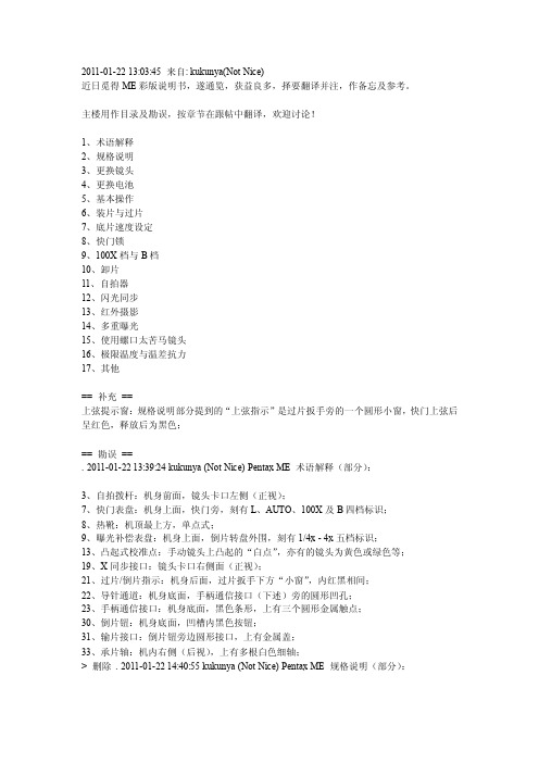
2011-01-22 13:03:45 来自: kukunya(Not Nice)近日觅得ME彩版说明书,遂通览,获益良多,择要翻译并注,作备忘及参考。
主楼用作目录及勘误,按章节在跟帖中翻译,欢迎讨论!1、术语解释2、规格说明3、更换镜头4、更换电池5、基本操作6、装片与过片7、底片速度设定8、快门锁9、100X档与B档10、卸片11、自拍器12、闪光同步13、红外摄影14、多重曝光15、使用螺口太苦马镜头16、极限温度与温差抗力17、其他== 补充==上弦提示窗:规格说明部分提到的“上弦指示”是过片扳手旁的一个圆形小窗,快门上弦后呈红色,释放后为黑色;== 勘误==. 2011-01-22 13:39:24 kukunya (Not Nice) Pentax ME 术语解释(部分):3、自拍拨杆:机身前面,镜头卡口左侧(正视);7、快门表盘:机身上面,快门旁,刻有L、AUTO、100X及B四档标识;8、热靴:机顶最上方,单点式;9、曝光补偿表盘:机身上面,倒片转盘外围,刻有1/4x - 4x五档标识;13、凸起式校准点:手动镜头上凸起的“白点”,亦有的镜头为黄色或绿色等;19、X同步接口:镜头卡口右侧面(正视);21、过片/倒片指示:机身后面,过片扳手下方“小窗”,内红黑相间;22、导针通道:机身底面,手柄通信接口(下述)旁的圆形凹孔;23、手柄通信接口:机身底面,黑色条形,上有三个圆形金属触点;30、倒片钮:机身底面,凹槽内黑色按钮;31、输片接口:倒片钮旁边圆形接口,上有金属盖;33、承片轴:机内右侧(后视),上有多根白色细轴;> 删除. 2011-01-22 14:40:55 kukunya (Not Nice) Pentax ME 规格说明(部分):类型:35mm全幅SLR相机,光圈优先自动曝光,电子焦平面快门,全开光圈中央重点式TTL测光;镜头卡口:宾得K卡口;标准镜头:SMC 50/1.2,SMC-M 50/1.4,SMC-M 50/1.7,SMC-M 40/2.8;快门:精工(Seiko)MFC 纵走式金属焦平面,电子自动控制8 - 1/1000秒;手动控制机械1/100秒;B门;具有快门锁定和上弦指示("Cocked" indicator);闪光同步:X同步接口,热/冷靴接口,闪光同步1/100秒;自拍器:4 - 12秒延时快门;取景器:镀银五棱镜取景器,裂像及微棱对焦屏,92%视野率,0.97x放大率(50mm镜头,无穷远),目镜屈光度-0.5,取景器内LED红点快门速度指示和过/欠曝警告,目镜框可安装M型镜片校正转换器、M型放大器和M型直角取景器;过片及倒片:单次扳动过片,过片行程135°,预备角30°,快速倒片手柄;自动手柄:ME机身可安装使用1.5张/秒的自动连拍手柄,连续或单张曝光;测光表:全开光圈中央重点TTL测光,GPD测光元件快速响应,LED曝光读数,卷片手柄及快门按钮兼做测光快关;测光范围EV1 - EV19(ASA100,f/1.4),胶片ISO设定范围12 - 1600;电池:两节1.5V银芯电池(G13),测光LED指示电池电量;后背:可换ME日期后背;> 删除. 2011-01-22 14:49:45 kukunya (Not Nice) Pentax ME 更换镜头:1、镜头红点对准机身卡口红点,按下并顺时针旋至“滴答”一声为锁定;2、暗处难以看见红点时,将镜身凸起式校准点对齐机身卡口释放按键,按下并顺时针旋至“滴答”一声为锁定;注意:1、在没有前后盖时若需放置镜头,务必将镜头前组向下放置,切勿(NEVER)后组向下放置;2、室外更换镜头时,若机身内装有底片,注意避免阳光直射;> 删除. 2011-01-22 15:04:42 kukunya (Not Nice) Pentax ME 更换电池:1、安装电池用硬币旋开底面电池仓盖,放入两节电池,正极向下,旋紧电池仓盖;LR44碱性纽扣电池亦可;2、检查电池:正常情况下,一组新电池可使用一年或支撑快门动作约10000次;半按快门若取景器内一个LED指示灯亮起则电池为激活状态,若LED指示灯闪烁则电力不足,应尽快更换,若无LED指示灯亮起,则电池已不可使用;请随身携带备用电池;> 删除. 2011-01-22 15:15:00 kukunya (Not Nice) Pentax ME 基本操作(从略,重点翻译测光部分):基本步骤1 - 7:上卷- 曝光补偿置为0 - 设定对应底片速度- 设定镜头光圈- 快门表盘置为AUTO - 过片- 对焦8、测光:将过片扳手稍外拉至预备角(约30°,将开启一个电池开关),轻按快门释放钮(即半按,将开启另一个电池开关),开启测光系统,取景器内某个LED指示灯将会亮起,指示自动选择的曝光快门速度;若预设的光圈值会导致过曝或欠曝,“OVER”或“UNDER”旁的LED指示灯将亮起以示警告;9、完全按下快门释放钮,电子快门将按照LED指示的速度释放,完成曝光;> 删除. 2011-01-22 15:45:29 kukunya (Not Nice) Pentax ME 装片与过片:1、向上拉动倒片旋钮即可打开后盖;2、胶卷置入片仓,按下倒片旋钮,拉出片头并插入承片轴上任意两根白色细轴之间;3、交替扳动过片扳手和释放快门按钮,直至胶片上下边缘小孔均准确套上齿轮,合上后盖;4、扳动过片扳手并确认倒片旋钮随之逆时针转动,则装片正确,底片随过片而从片盒内移动至承片轴上;如果装片正确,过片/倒片指示窗口会“闪动”;按动快门,过片至计数器指示为“1”,即可开始拍摄;注意:1、上述步骤3、4应在快门表盘置为100X情况下操作,以避免不必要的电力浪费(同时可以避免慢速快门带来的等待时间,译注);2、拍摄前切记将快门表盘置回AUTO档;> 删除. 2011-01-22 16:05:10 kukunya (Not Nice) Pentax ME 底片速度设定:轻提曝光补偿表盘边缘,并旋转至底片对应的ASA指示值即可;表盘上可用的ASA依次为:1600,#1250,#1000,800,#640,#500,400,#320,#250,200,#160,#125,100,#80,64,#50,#40,32,#25,20,#16,12;其中加#的为表盘上仅以圆点标出而未注明具体数值的档位;> 删除. 2011-01-22 16:20:07 kukunya (Not Nice) Pentax ME 快门锁:为避免上弦后的快门被误操作,可按下快门表盘旋钮上的白色按钮,并旋转至“L”档,即可锁住快门;当希望转回至AUTO档时,无需按下白色按钮,直接旋转即可,当转至AUTO 档后,白色按钮会自动弹起并锁定旋钮;注意:当未取下镜头盖或在极暗的环境下时,按下处于AUTO档的快门,反光镜可能会锁定,进行超长时间的曝光;此时若需修正,请将快门表盘旋钮旋至100X档即可迅速关闭快门;下次拍摄前请确认快门表盘旋钮置回了AUTO档;> 删除. 2011-01-22 16:32:33 kukunya (Not Nice) Pentax ME 100X档与B档1、100X档为1/100秒机械快门,快门将维持工作在1/100秒速度,可以在没有电源的情况下配合光圈完成正确曝光;2、100X档同时用于配合电子闪光灯使用,后述;3、B档(Bulb)用于长于8秒的曝光控制,使用时先安装快门线至快门释放按钮,档快门线上的活塞按下期间,快门将持续开启;对于长达几分钟至几小时的曝光,请使用带有锁定装置的快门线;> 删除. 2011-01-22 16:41:57 kukunya (Not Nice) Pentax ME 卸片当一卷底片拍完最后一张后,过片扳手将会无法扳动(此时切勿用力扳动!),则需要更换底片;翻出倒片手柄,按下底面倒片钮,顺时针转动扳手从而将底片卷回片盒;若倒片顺利,过片/倒片指示窗口将会“闪动”,当倒片手柄上的紧张感突然减弱,说明片头已从承片轴上脱离,打开后盖,取出片盒;注意:1、卸片操作时尽量避免光线直射;2、片头脱落后即无需再旋动倒片扳手,以免片头缩入片盒造成不便——译注;> 删除. 2011-01-22 16:48:00 kukunya (Not Nice) Pentax ME 自拍器:自拍器延时范围为4 - 12秒,取决于自拍钮被拨动的程度;要使用自拍,将自拍钮逆时针拨动至静止状态,轻轻回拨自拍钮即可开始计时;> 删除. 2011-01-22 17:00:12 kukunya (Not Nice) Pentax ME 闪光同步:ME具有一个X同步接口和一个位于热/冷靴插槽内的独立X触点;热/冷靴触点在未插入闪光灯至热/冷靴时将不会接通,这是由靴内插槽下方的一个微型开关控制的,可以有效避免使用X同步接口时此处造成触电的危险;如果您使用的闪光灯有靴型插口,请将其插入机顶热/冷靴使用,如果您的闪光灯不适用于靴型插槽,请将其引线插至机身上的X同步接口;当使用电子闪光点时,务必将快门表盘旋钮旋至100X档,这是可供闪光灯使用的最高快门速度;> 删除. 2011-01-22 17:06:48 kukunya (Not Nice) Pentax ME 红外摄影:当希望拍摄红外照片时,请使用镜头景深表中橙色线标出的红外对焦标记,步骤如下:1、正常对焦至拍摄对象清晰;2、从对焦环上读出拍摄对象至相机的距离;3、调整对焦环,将红外对焦标记对准对焦环上刚才读到的距离;例如当对焦于无穷远处时,即将对焦环上无穷远位置对准红外对焦标记即可;注意:1、使用黑白红外底片时需要作上述对焦修正,使用彩色红外底片则不需要;2、红外对焦标记即镜头景深表上除中线外的橙色细线,亦有用红点或“R”标识的——译注,感谢smallandred、方方和quitsky同学提供帮助;> 删除. 2011-01-22 17:18:35 kukunya (Not Nice) Pentax ME 多重曝光:当试图多重曝光时,步骤如下:1、使用正常的曝光操作进行第一次曝光;2、旋转倒片手柄,将片盒内的底片旋紧,并保持倒片手柄位置(keep hold of the rewind knob);3、按下倒片钮并过片,这将在不过片的情况下为快门上弦;4、最后,释放快门完成第二次曝光;注意:1、完成多重曝光之后,请空拍一张,防止底片上影像重叠;2、由于计数器在每次快门上弦均会计数,两重曝光的一次拍摄将会在计数器上反映为两张;> 删除. 2011-01-22 17:47:00 kukunya (Not Nice) Pentax ME 使用螺口太苦马镜头:通过K型转接环,传统的螺口Takumar镜头(包括Super-Takumar和SMC Takumar)可以很容易地使用在您的ME机身上,然而,使用转接时会有以下问题:1、由于耦合系统的差异,自动光圈将无法工作;2、全开光圈测光的镜头将工作在收缩光圈测光状态;具体转接部分从略;--PS:验证码居然是mount,天意啊~~~> 删除. 2011-01-22 18:04:36 kukunya (Not Nice) Pentax ME 极限温度与温差抗力:您的ME相机将在摄氏50°至零下20°范围内正常工作,然而低温下被污染的润滑油可能会影响其对低温的耐受力,因此为确保相机在低温下正常工作,需要彻底检查并更换润滑油;突然的温度变化可能会导致相机内部受潮,并可能造成生锈,对相机机械结构造成极大伤害;如果从温暖环境突然进入低温环境,可能导致冷凝而造成更大伤害;因此应当尽量避免突然的温度变化,我们建议在温差超过10摄氏度的环境间应采取分步适应的方法,并保持30分钟以上适应时间,如果难以实现,将相机装入保护袋或相机包中可以减小温度突变带来的伤害;另外,低温将会影响电池的性能,所以应尽量避免低温使用,或尝试仅在拍摄前即时安装电池;温度极低时,应使用新电池;> 删除. 2011-01-22 18:19:33 kukunya (Not Nice) Pentax ME 其他以上是我的选择翻译,没有翻译的部分包括:1、曝光补偿的使用场合及方法;2、不同场合建议的光圈设定值(类似阳光十六法);3、裂像微棱对焦屏的使用方法;4、保持相机稳定的拍摄姿势;5、景深表的使用;6、全开光圈测光镜头与收缩光圈测光镜头;7、日常相机保养;8、免责条款;9、ME腰带夹:这个是ME的配件,可以装上机身,然后别在腰带上,亮骚利器,见过淘宝有人卖,比相机还贵,>_<10、以上翻译中另有说明从略的部分;以上如有需要,可以跟帖说明,我补充翻译;另外由于包含一些基于个人经验的注释,限于水平有限,如有错误或疑问之处欢迎讨论,我将在主楼设置勘误;。
美国优倍 安全栅样本及技术手册
单/双通道电压输入,单/双路输出··········································14
单/双通道开关量输入,开关量输出·········································16
检测端(输入端)安全栅
单/双通道热电偶输入,单/双路输出··········································6
单/双通道热电阻输入,单/双路输出··········································8
单/双通道二、三线制电流输入(配电功能),单/双路输出·································10
安全栅的基本知识···········································首页
安全栅的基本知识·············································1
安全栅通用技术指标············································5
中国国家防爆电气产品质量监督检验中心是中华人民共和国地区监督生产安全防爆产品的权威机构,对本安型安全栅产品有着严格、科学、详细的规定,只有通过该监督站认证的企业及其所开发生产的产品才具备符合标准的安全性能,否则可能会给使用方的设备、人员和生产造成无可估量的损害。
术语解释:
关联设备
一种安装在安全场所,本安电气设备与非本安电气设备之间的相连的电气设备。
输入信号故障输出方式及指示设定·····································34
ME-C主机说明书

燃油柱塞
液压活塞 FIVA 比例 阀
燃油压力 8Bar
蓄压器
滑阀式 喷油器
放泄
高压液压油进口
-
34
液压管
排气阀促动 器 FIVA 阀
隔膜蓄压器
排气系统
排气阀杆
高压液压油进口
-
35
-
36
新式排气阀
-
37
排气阀
关闭排气阀 的空气弹簧 尺寸减小
-
新式油缸 新式空气缸 新式排气阀 杆
38
排气阀
大连船用柴油机有限公司
大连船用柴油机有限公司技术处 2012年7月
-
1
5S60ME-C8.2 柴油机技术介绍
-
2
MAN二冲程主机型号定义 • 5 S 60 ME-C MK 8.2
Mark:主机版本号
设计
内容 主机设计程序
C:紧凑型主机 B:排气定时由凸轮控制 C: 凸轮控制
E: 电控技术
活塞直径,单位:cm S:超长冲程:约4.0
ECU用于对各个控制单元进行控制; CCU对每个气缸进行控制,包括燃油喷射、排气阀开闭、 气缸注油和起动阀动作等; ACU对辅助鼓风机、液压动力单元进行控制及工况监测; EICU用于对主机与外部系统进行集中接口。
-
46
气缸控制单元CCU
通过FIVA控制燃油喷射和 排气定时 监测燃油促动泵柱塞位置 监测排气阀杆位置 控制起动阀 控制注油器注油
-
64
连杆
十字头
滑块
-
65
4.减重式中间体
中间体一改往日笨重的设计,变的得可靠又轻 便,同时为减少加工量,新设计将原中间体两侧的 加工面改为焊前成品。
ME60现场维护手册
ME60维护手册目录ME60维护手册 (1)1.ME60-16 (2)ME60-8 (4)2.温湿度要求 (6)3.机房洁净度要求 (7)4.防腐蚀性气体条件要求 (8)5.ESD防护要求 (9)6.防雷接地要求 (10)7.直流基础电源要求 (12)8.直流基础电源建议 (12)9部件更换概述 (13)9.1基本操作流程 (13)9.2更换主控板 (15)9.3更换交换网板 (22)9.4更换LPU板 (29)9.5更换光模块 (35)9.10.更换ME60的防尘网 (38)9.11更换网线 (42)9.12更换光纤 (43)1.ME60-16ME60-16机箱高36U(1U=44.45mm),外形尺寸为442mm³669mm³1600mm(宽³深³高)。
设备外观如图1所示,设备部件如图2所示。
图1 ME60-16设备外观示意图图2 ME60-16设备部件示意图ME60-16为一体化机箱设计,其主要组成部件及简介如表1所示。
ME60-8ME60-8机箱高20U(1U=44.45mm),外形尺寸为442mm³ 669mm³886mm(宽³深³高)。
设备外观如图1所示,设备部件如图2所示。
图1 ME60-8设备外观示意图图2 ME60-8设备部件示意图ME60-8为一体化机箱设计,其主要组成部件及简介如表1所示。
2.温湿度要求为保证设备始终具有良好的工作状态,在机房内需维持一定的温度、湿度,并需保证机房的海拔高度在规定范围内。
具体要求如表1所示。
说明:为达到上述要求,可对机房采取如下措施:∙不论气候条件,均应设置长年的温控装置。
∙对于干燥的地区可采用加湿机、定期用湿拖布拖地板来保证环境湿度。
∙湿度过大的地区,可采用抽湿机。
3.机房洁净度要求室内灰尘落在机体上,可造成静电吸附,使金属接插件或金属接点接触不良,不但会影响设备寿命,而且易造成设备故障。
MECB60英文说明书

MECB60DIESEL ENGINE CONTROL BOXUSER MANUALSMARTGEN (ZHENGZHOU) TECHNOLOGY CO., LTD.All rights reserved. No part of this publication may be reproduced in any material form (including photocopying or storing in any medium by electronic means or other) without the written permission of the copyright holder.Applications for the copyright holder’s written permission to reproduce any part of this publication should be addressed to SmartGen Technology at the address above.Any reference to trademarked product names used within this publication is owned by their respective companies.SmartGen T echnology reserves the right to change the contents of this document without prior notice.Table 1 - Software VersionCONTENTS1. OVERVIEW (3)2. PERFORMANCE PARAMETERS (3)3. FUNCTIONS AND OPERATIONS (4)3.1 DISPLAY FUNCTION (4)3.2 CONTROL FUNCTION (5)3.3 START AND STOP OPERATION IN REMOTE CONTROL MODE (7)3.3.1 DESCRIPTION (7)3.3.2 REMOTE START SEQUENCE (7)3.3.3 REMOTE STOP SEQUENCE (8)3.4 START AND STOP OPERATION IN LOCAL CONTROL MODE (8)3.4.1 DESCRIPTION (8)3.4.2 LOCAL START SEQUENCE (8)3.4.3 LOCAL STOP SEQUENCE (8)4. OPERATION AND USE (9)4.1 CHECK BEFORE USE (9)4.2 LOCAL CONTROL OPERATION STEPS (9)4.2.1 STRAT (9)4.2.2 STOP (9)4.3 REMOTE CONTROL OPERATION STEPS (9)4.3.1 START (9)4.3.2 STOP (9)4.4 BACK PANEL (10)5. CONTROL BOX WIRING DIAGRAM (10)6. CASE DIMENSION (13)7. NOTES (14)8. MAINTENANCE (14)9. TROUBLESHOOTING (14)10. PACKING LIST (14)1. OVERVIEWMECB60 diesel engine control box (hereinafter “control box”) is mainly composed of HMC6000A 2 diesel engine controller, with security interface. The control box integrates digitization, intelligentization and network technology, which can be used in the automatic control system of a single diesel engine. It can realize the functions of local start, stop, remote start, shutdown, data measurement, display, alarm protection and other functions of the diesel engine, and the operation is safe and reliable. The control box is equipped with a remote monitoring interface to realize the remote start-up and shutdown functions of the engine by receiving the remote start-up and automatic start-up instructions.2. PERFORMANCE PARAMETERSItems ContentsPressure Measure Range 0~1MPaFuel Output 16A Connected to common outputStart Output 16A Connected to common outputCase Dimension 353mm×240mm×200mm(shock absorber height is exclusive) Installation Dimensions 160mm×65mm,4*φ6.5 panel cutoutWorking Conditions Temperature: (-25~+70)°C Humidity: (20~93)%Storage Conditions Temperature: (-30~+80)°CProtection Level IP65Weight 4.5kg3. FUNCTIONS AND OPERATIONS3.1 DISPLAY FUNCTIONThe HMC6000A 2 controller (here inafter “controller”) in control box can display data and operation status. It mainly includes main interface display and measured data display on controller LCD.The main interface display includes a tachometer display range of 0 ~ 3000r/ min, a thermometer display range of 0~150℃, an oil pressure gauge display range of 0 ~ 1000 kpa, and power supply voltage display. The main interface display is shown in Figure 1.Figure 1: Main Interface Displaya) The measurement data display page includes start times, oil temperature, charger, power supply A, power supply B, and cumulative operation, as shown in Figure 2.b) The alarm page displays various warning alarms and shutdown alarms detected by the controller, as shown in Figure 3.c) The event log page records all downtime events and time, as shown in Figure 4.d) The controller information includes software version, release date, time, input and output port status, etc., as shown in T able 3.Start times 5Oil temp. 35℃Battery charger 13.8VPower supply A 12.7VPower supply B 12.8VAccumulated operating time:3.0hFigure 2: Measurement Data DisplayAlarm 01/02Warning alarmWater temp. open circuit warningOil temp. open circuit warningOil pressure open circuit warningFigure 3: Alarm DisplayEvent log 01/01EventsLocal start2020-06-12 13:31:41Figure 4: Event Log DisplayTable 3 - Controller Information Display Interface Interface Display DescriptionPress ENTER for 1 second, then enter controller parameter setting and controller information selection interface. ReturnParameter settingController informationAfter selecting the controller information, pressENTER to enter the controller informationinterface.The first screen Controller informationSoftware version:1.1Issue date:2018-09-052018.10.15(5)09:30:10 This screen displays the software version, hardware version and controller time.Press can flip the screen.The second screen O:S F S H A 1 2 3 4 56 7 8 9 10 11 12Engine standby This screen can display the output port status and engine status of the controller.Press or can flip the screen.S:Starting relay output; F: Fuel relay output; S: Shutdown relay output; H: Audible alarm relay output; A: Public alarm relay output.The third screen I: E 1 2 3 4 5 6 7 8 910Engine standby This screen can display the input port status and engine status of the controller.Press or can flip the screen.3.2 CONTROL FUNCTIONThe control box can control the engine start, shutdown, alarm protection and other functions in the local and remote control modes.The control box is equipped with a remote monitoring interface, which can control the engine start, stop, noise reduction and other operations remotely. Various parameters and records of the engine can be displayed on the remote monitoring controller in real time.The remote monitoring controller can control the engine only in the remote control mode, and other control keys do not work except for emergency stop in the local mode.The control box panel layout is shown in Figure 5.Figure 5: Control Box PanelThe functions of keys / knobs configured in the control box are shown in T able 4:Table 4 - Function Description of Control Box KeyKey/Knob Function DescriptionLocal /RemoteControlMode conversion of localremote controlAfter turning this knob, the system switches to "localmode / remote control mode". Turning to "remotecontrol", the diesel engine is in the remote control state,the "start" and "stop" functions of the remote instrumentare effective, while the "start" and "stop" functions of thelocal instruments are not effective; if the diesel engine isturned to "remote control", the "start" and "stop" functionsof the remote instruments are not effective, while the"start" and "stop" functions of the local instruments areeffective.OverrideModeOverride modeIn override mode, only over speed and manualemergency shutdown can stop the engine.EmergencyStopEmergency stopWhen an emergency occurs, press this key, the fueloutput of the controller will be disconnected, theemergency stop output will be output, and the engine willstop immediately.Key/Knob Function DescriptionNormal Mode / EmergencyMode Normal mode / emergencymode switchingWhen emergency start is required, turn the side "normalmode / emergency mode" knob to "emergency mode"position.EmergencyStart Emergency startIn the emergency mode, press the "emergency start" keycan switch on the motor and start the engine.The functions of controller keys are shown in Table 5:Table 5 - Key Function Description Keys Function DescriptionStop In the standby mode, the running engine can be stopped.In the process of shutdown, press this key again to stop the machine quickly.Start In the standby mode, press this key to start the stationary engine. Mute The sound alarm of the controller can be eliminated.Self-checking Press this key to test the speed in standby mode.Reset Press this key, if the controller has an alarm, it can reset the alarm. Lamp T est Press this key to test the panel LED and screen.Home Can quickly return to the first screen display interface.Event Log Can quickly go to the alarm record page.Up/Increase 1.Screen scroll.2.Up cursor and increase value in setting menu.Down/Decrease 1.Screen scroll.2.Down cursor and decrease value in setting menu.Set/Confirm 1. Press this key for over 1 second to enter the parameter setting and controller information selection interface.2. Confirm the setting information in the settings.3.3 START AND STOP OPERATION IN REMOTE CONTROL MODE3.3.1 DESCRIPTIONTurn the knob to "Remote control mode". After the remote control mode is effective, the start / stop operation can be carried out on the remote monitoring module.3.3.2 REMOTE START SEQUENCE1) When the "remote start information" is valid, the preheating relay outputs (if configured), and the LCDstatus page displays the "preheat" countdown.2) After preheating, the fuel relay outputs for 1s, and then starts the relay output; if the engine fails tostart successfully within the "start time", the fuel relay and start relay stop output and enter the "startinterval" to wait for the next start.3) Within the set starting times, if the engine fails to start successfully, the controller will send out a startfailure alarm, and the LCD Alarm page will display the start failure alarm.4) In any start, if the start is successful, the "safety delay" will be entered. After the safety delay, the"start idle" will be entered (if the start idle time delay is configured).5) When the start-up idle time delay is over, the controller enters "high-speed warm-up" (if thehigh-speed warm-up delay is configured).6) When the high-speed preheating delay ends, the engine runs normally.3.3.3 REMOTE STOP SEQUENCE1) When the "stop signal" is effective, start "high-speed heat dissipation".2) After the high-speed heat dissipation is finished, the idle speed relay is powered on and outputwhen entering the "stop idle" (if configured).3) When the idle speed is over, the power on shutdown relay is powered on and the fuel relay output isdisconnected.4) After the power on shutdown delay is over, enter "waiting for stable stop" to automatically judgewhether it is stopped stably.5) If the engine stops stably, it will enter into "engine standby"; otherwise, the controller will enter theshutdown failure state and issue a shutdown failure warning (after the shutdown failure alarm, if the engine stops stably, it will enter "engine standby")3.4 START AND STOP OPERATION IN LOCAL CONTROL MODE3.4.1 DESCRIPTIONTurn the knob to "Local mode". After the local mode is effective, you can start / stop the machine by pressing the key on the controller.3.4.2 LOCAL START SEQUENCE1) After pressing, the preheating relay outputs (if configured), and the LCD status page displays"preheating" countdown;2) After the preheating delay is over, the fuel relay outputs 1s, and then starts the relay output; if theengine fails to start successfully within the "start time", the fuel relay and start relay stop output and enter "power on shutdown".3) In any start, if the start is successful, it will enter the "safety delay".4) When the safety delay is over, if the speed, water temperature and oil pressure of the controller arenormal, the controller will directly enter into "normal operation".3.4.3 LOCAL STOP SEQUENCE1) When press, you can enter "shutdown delay". The shutdown relay is powered on and the fuelrelay output is disconnected.2) After shutdown delay is over, enter "waiting for stable stop" to automatically judge whether it isstopped stably.3) If the engine stops stably, it will enter the "engine standby" mode; otherwise, the controller will enterthe shutdown failure state and issue a shutdown failure warning (after the shutdown failure alarm, if the engine stops stably, it will enter "engine standby").4. OPERATION AND USE4.1 CHECK BEFORE USEBefore the control box is used for the first time or after maintenance, after checking the external wiring of the control box, turn on the power switch, and the display screen of the controller is on.Before starting, make sure that the engine has no shortage of oil and water and meets the starting conditions.4.2 LOCAL CONTROL OPERATION STEPS4.2.1 STRATa) Turn on“Power Supply” and the display screen of the controller will light up and display theparameters.b) Press the green start key, the engine will start according to the set program, and display theparameters.4.2.2 STOPa) Remove the load.b) Press the red "stop" key to stop the engine until it stops stably.c) Turn off the power switch.4.3 REMOTE CONTROL OPERATION STEPS4.3.1 STARTa) Turn on the "Power Supply" of the local control box, the display will be on, turn the "local /remote control" knob to the remote control position, and the controller will display "remote control mode".b) In the remote control mode, after receiving the "remote start signal" command, the enginestarts according to the set program, the display screen shows the parameters, and automatically turns to normal operation.4.3.2 STOPa) Remove the load, the engine starts to stop until it stops stably.b) Turn off “Power Supply”.4.4 BACK PANELFigure 6: Controller Back Panel 5. CONTROL BOX WIRING DIAGRAMFigure 7: Control Box Wiring DiagramFigure 8: Security ModuleTable 6 - Wiring Description of Safety Module Terminal Pin Definition Cable Size Description1 Spare /2 Spare /3Security oilpressure VCC1.0mm2Power supply for security oil pressure sensor4Safety oilpressure GND1.0mm2Common terminal of security oil pressure sensor5Security oilpressure OUT1.0mm2Security oil pressure sensor input6 Security speed A 1.0mm2Connect the speed sensorPin Definition Cable Size Description7 Security speed B 1.0mm2Connect the speed sensorFigure 9: Remote MonitorTable 7 - Wiring Description of Remote Monitor TerminalPins Definition Specification Description1 Power supply+ 2.5mm2Remote power supply B+2 Power supply- 2.5mm2Remote power supply B-3 Override mode 1.0mm2Override mode input(I)4 Emergency stop 1.0mm2Emergency stop input5 CANL 0.5mm26 CANH 0.5mm2Used to access the remote monitoring module 7 Shielded ground 0.5mm2Figure 9: ControlTable 8 - Wiring Description of Control TerminalPins Definition Specification Description1 Spare /Pins Definition Specification Description2 Power supply+ 2.5mm2DC working power supply positive input.3 Start output+ 2.5mm2Start relay output4 Parking+ 1.5 mm2In the local status, press the stop key to disconnect the ECU ignition switch power supply to realize the shutdown. When the speed is too high, the water temperature is too high, and the oil pressure is too low, the ECU ignition switch power supply is disconnected to realize the shutdown.5 Fuel leak A 1.0mm2Fuel leakage input6 ECU powersupply+2.5mm2DC working power supply positive output7 ECU powersupply+2.5mm2DC working power supply positive output.8 CANH 0.5mm2used to access the engine ECU with J1939 interface.9 Spare /10 Power supply+ 2.5mm2DC working power supply positive input.11 Start output+ 2.5mm2Start relay output12 Spare /13 Spare /14 Spare /15 Spare /16 Power supply- 2.5mm2DC working power supply negative input.17 Power supply- 2.5mm2DC working power supply negative input.18 Generator D+ 1.0mm2The D + terminal input of charging generator is not allowed to be grounded.19 Blank /20 Fuel leak B 1.0mm2Fuel leakage input common terminal, internal connection (B -)21 Spare /22 Spare /23 CANL 0.5mm2It is used to access the engine ECU with J1939 interface.6. CASE DIMENSION7. NOTEa. Before starting the engine, make sure the engine has the starting conditions!b. Do not repair the components inside the control box during operation!c. Do not disconnect the battery during operation!d. Do not press the stop and reset buttons at will during operation!8. MAINTENANCEa. When the control box is stored separately, it must be placed in a dry place, and there is no corrosive medium in the air.b. Check the fasteners and terminal blocks regularly to prevent looseness. If the wiring is loose, the wiring should be aligned.c. Regularly remove the dust and dirt at each conductive contact to ensure good electrical contact.9. TROUBLESHOOTINGTable 9 - Troubleshooting10. PACKING LIST_________________________________。
美必盛两翼自动门操作说明书
0 目录0 目录-------------------------------------------------------11 简介-------------------------------------------------------12 技术描述---------------------------------------------------53操作特性--------------------------------------------------164维护保养--------------------------------------------------205简单故障排除----------------------------------------------21附录------------------------------------------------------251 简介1.1 安全操作1.2 前言1.3 版权1.4 使用须知1.5 专业名词缩写1.6 选装部件1.1 安全操作美必盛自动门的设计、检验和生产是依据严格的国际标准进行的。
进行每年一次的常规维护时应确保操作程序正确(在经常使用的情况下)。
所有的工作必须由美必盛公司或美必盛公司认可的经销商来完成。
在进行操作之前必须先阅读操作手册。
警告:尽量避免接触转动部分。
如果对操作手册有任何疑问,请与宁波美必盛公司联系。
美必盛自动门地址:联系电话:网址:1.2 前言操作手册是专门为自动门的用户提供的,它向你提供如下信息:门的操作门的结构门的维护1.3 版权本操作手册是由公司提供和认可的。
它只提供给自动门的所有者和公司认可的代理商。
公司保留一切权力。
本操作手册信息的所有权归美必盛公司。
在没有得到美必盛公司的书面认可之前,将本操作手册的信息或其中的一部分泄漏给第三者是不允许的。
美必盛公司保留改进产品而不另行通知的权力。
艾米克计量泵

意大利爱米克 地面垂直方向; 4. 确认电源是否与铭牌上的规格相同。
步 骤 二 :连 接 讯 号 控 制 的 机 型 ,先 切 至 手 动 模 式 ,将 计 量 泵 的 频 率、冲程调至最大,再将排气阀打开: 1. 药液若不能从排气阀排出,表示泵头到药桶之间的部分有问
题; 2. 药液若能从排气阀排出,表示泵头上的吐出阀至加药点的注
意大利爱米克
连接至计量泵 BNC 接头 吸入管 液位侦测器(此机 型不含) 底阀及滤网
六、 操作面板说明
软管 旋紧螺帽
固定垫圈
奶嘴头 密封圈 阀体
电源开关 电源指示灯
频率调整旋钮
频 率 调 整 旋 钮 : 设 置 加 药 频 率 ( 0~100%, 最 大 180 下 /分 )。
说 明 :假 设 计 量 泵 流 量 为 10 升 /时 ,当 频 率 旋 钮 调 到 50%位 置 时 , 则加药频率为 90 下/分,所以流量为 5 升/时。
计量泵使用单相 220V 电源,安装时请依照下列步骤: 1. 确认供应电源是否与计量泵电源规格相同; 2. 计 量 泵 应 提 供 一 组 独 立 的 电 源 使 用 ,如 电 源 并 未 接 地 则 须 加
装一个 0.03A 的漏电保护器; 3. 不可将计量泵的电源和其它大型负载并联连接-如大功率
意大利爱米克 "VCO"计量泵用户手册
本 手 册 包 含 人 员 安 全 方 面 相 关 资 料 ,如 不 理 会 将 会 危 害 到 人 身的安全。
计量泵禁止使用于具放射性的化学药品上。
计量泵安装时尽量避免安装于阳光直接照射以及水直接喷 溅的位置。
上海桦微自动化科技有限公司
RR44009900662112
CB系列电源供应器使用说明书

3. 将 24-pin 主输出接头连接至主板上的 24-pin 对应插槽。
4. 将 8-pin + 12V 接头连接至主板的对应插槽。 A. 如果您的主板上有一个 8-pin + 12V 插槽,可 直接连接 8-pin 接头到主板上。 B. 如果您的主板有一个 4-pin 插槽,取下另一个 4-pin 接头,并连接 4-pin 接头至主板上。
650mm
8 (4+4) Pin CPU
650mm
8 (6+2) Pin PCI-E
600mm
4 Pin Peripheral
100mm 100mm 100mm 550mm
SATA (90 Degree)
550mm 100mm
Floppy
150mm
安装电源
安装电源
1. 组装前请确认电源是否完全断电。
注意事项与保固范围
注意事项与保固范围
■ 保固范围
* 迎广电源供应器针对材质与工艺上的瑕疵保固, 由最初的消费者购买之单据上日期起,提供为期 7 年的有限保修。非原始购买者或非于通路购买 取得之产品,皆无法提供保修之服务。
* 本保固条款之适用范围,不包括以下因素: 1)滥用和误用, 2)未按照指示操作, 3)未经 本公司授权之技术人员维修或拆装,4)以及更改 此产品。
< 25dBA
0~50℃ OCP/OVP/UVP/SCP/OTP/OPP CCC 180 x 150 x 86mm 220 x 360 x 100mm 3.4kg 4.0kg 7年
1
2 6 3 16 1
交流输入 直流输出 最大输出电流 最大功率
+12V 87.5A 1050W
ALINCO 605说明书 转贴

1.左边的小旋钮是调节VHF音量的,在下面称之为VHF,右边的小旋钮是调节UHF音量的,在下面称之为UHF2.两种显示方式:信道模式(CH模式)频率模式:VFO,压控振荡器模式,频率可连续调节Menmory,记忆模式(频率和信道CH同时显示) Call模式,V段U段的频率模式可分别选择,互不影响启动CH模式,V/M+VHF+PWR(同时按住V/M和VHF开电源)关闭启动CH模式,V/M+call+PWR(同时按住V/M和UHF开电源)3.双段机工作时UV段可同时接受,在同一时间内只有一个波段可以发射,称之为主波段main-band,另一个成为次波段sub-band,分别按vhf和uhf选择.4.按键的含义(括号里为第二功能):V/M(MW),VFO模式/Memory记忆模式(Menory write记忆模式写入) Mhz(shift),M赫兹位(shift,频率偏移,异频收发,可以+_或同频) Monitor(T.SQL),监视,即屏蔽静噪功能直接接受,(亚音频及亚音频静噪) T.O.T(LOCK),发射时长限制(锁键) CAll(H/L),call信道(高低功率转换)5.面板按钮有三种功能,通过三种方式操作:直接按下并放开FUNC(功能,以下简称F)之后按住F(不放)首要功能直接按下列键,对应的功能:VHF,选择vhf作为主波段,并可在异频收发时按照1Mhz快速调整频差(_) UHF,选择UHF作为主波段,并可在异频收发时按照1Mhz快速调整频差(+) PWR(电源开关) DAIL(大旋钮) ,当VFO模式时改变频率,记忆模式或信道模式时改变信道CH V/M.在VFO模式和Menory记忆模式之间切换Mhz,按下之后,大旋钮按照1Mhz的步进改变MONITOR,屏蔽静噪功能,直接收听(适用于弱信号的收听),启动发射限时功能(防止发射时间过长损坏发射机) CALL,调出call频道第二功能:先按F键,放开,当屏幕上显示F时,按下下列键,出现对应功能: VHF,降低主波段的静噪阀值(注意,在调整静噪之前首先把希望调整的波段设为主波段) UHF,提高主波段的静噪阀值DAIL(大旋钮),改变记忆模式的信道CH编号V/M(MW),在VFO模式下,把当前频率写入所选的信道CH/在记忆Memory模式下,按此键,则当前CH在扫描时将被跳过,称之为skip Mhz(shift),选择异频收发的方式(+或_)和频差,按下F键,当屏幕显示F时,按此键,轮流显示+_和空,表示,正差,负差和不差频MONITOR(监视T.sql),启动亚音频编码器(机器自带,标准配置)和亚音频静噪功能. TOT(LOCK),按下F键,当屏幕显示F时,按此键显示T,表示开启了亚音频编码,同时显示出亚音频的频率,注意,是亚音频编码不是解码CALL(H/L),切换大小功率第三功能按住F键不放,再按相应的键VHF,启动9600bps数传模式,再次重复同样操作关闭该功能(AES,AON机器此功能正常,8EU,007机器进入数传模式后无法推出,只能复位) UHF,开/关操作提示音(哔哔音) DAIL(大旋钮),选择要保存的跨段收发的信道号CH V/M(MW),再VFO模式下,按此键把跨段频率写入所选的信道CH,主波段main-band是接受频率,次波段sub-band是发射频率Mhz(shift),进入步进设置,可选5 10 12.5.....50khz CAll(H/L),进入菜单6.开机功能按住相应键开机(PWR) VHF+PWR,启动跨段中继UHF+PWR,关闭跨段中继FUNC+PWR,整机复位V/M+VHF,开机,选择信道CH显示模式,不显示频率; V/M+CALL,开机,关闭信道CH显示模式V/M+MONITOR,开机,启动克隆模式,可将一台605的设置复制到另一台7.屏幕显示:F,可以按功能键进行设置,如无操作,5秒后消失T,亚音频编码启动,T.SQL亚音频静噪功能启动Mhz位小数点,闪烁表示正在扫描,消失表示当前CH是skip信道,扫描时将被跳过音频小数点(在100khz和10khz之间),一方面作为亚音频显示的小数点,当Mhz位小数点和音频小数点同时闪烁时表示正在忙模式扫描(busy mode)8.记忆模式信道存储(可保存收,发频,频率步进,异频偏移方向,大小,亚音频状态和大小)同频收发选择主波段调节频率(用大旋钮和Mhz可按Mhz和当前步进调节) 按F 用大旋钮选择希望保存的信道CH 按V/M(MW),保存-----------------------须在屏幕显示F时进行,如无操作,5秒后消失,如F消失,可重复上诉操作同段异频收发设置选择主波段调节接收频率(用大旋钮和Mhz可按Mhz和当前步进调节) 按F,在屏幕显示F时,按MHz(shift)键选择差频的方向(按MHzshift键依次显示- + 和空白),用大旋钮和VHFUHF(1MHZ步进)调整差频大小按F保存差频再按F键, 用大旋钮选择希望保存的信道CH 按V/M(MW),保存,屏幕显示+或-,表示这是一个收发异频的信道,同时标示了发频是+还是-跨段收发设置在次波段调整发射频率在主波段调整接受频率按下F键不放,用大旋钮选择希望保存的信道CH 按V/M(MW),保存---------在按下F键选择CH和按V/M保存的过程中,F 键始终按下不放. 屏幕同时显示+_,表示这是一个跨段信道*注:同段异频收发可在VFo模式和记忆模式下使用,跨段收发只能在记忆模式下使用(也许可以在纯信道显示模式下使用,没试)亚音频的设置在上诉各设置过程中,在保存之前,按F键,MONIRTOR(T.SQL),屏幕显示T表示亚音频启动(按动MONIRTOR/T.SQL,T轮流显示和消失,表示启动和关闭),同时可用大旋钮选择亚音频率删除信道在MOEMORY记忆模式下选择希望删除的信道按住F,按V/M9.三种扫描模式波段扫描,进入VFO模式,按手柄的up/down键1至2秒,按照机器设置的步进扫描整个波段,Mhz位小数点闪烁记忆模式扫描,进入记忆MEMORY模式,按手柄的up/down 键1至2秒,扫描所有的记忆模式的信道(可以选择某些信道不被扫描,即skip) 音调扫描,可扫描中继台使用的亚音频,需要安装亚音频解码器,在VFo模式下,按F,MONITOR(T.SQL)直到屏幕显示T.QSL(表示亚音频解码功能启动),按手柄上的UP/DOWN键主次两个波段可以同时扫描,并且扫描过程中可以切换主波段10.两种扫描恢复(释放)方式Timer定时模式,信号消失2秒或停顿达5秒之后释放,Mhz小数点闪烁busy忙模式,信号消失2秒之后释放,Mhz和100Khz位小数点同时闪烁两种释放方式的区别,busy模式只要信号持续,就不会释放,始终停留在此,而Timer模式即使有接受信号,在一定时间后(5秒)也会释放,继续扫描其它频率和信道.11. T.O.T发射限时功能按下T.O.T键,显示t oFF,再按显示p ,前者是表示限制连续发射的时间,用大旋钮可以选择off(不起作用),30 60 90...450秒后者用大旋钮选择被强制停止发射之后的恢复时间(即可以再次发射的时间)12.爆破音用于进入欧洲中继台,按下PTT,按手柄down键,发出单音(一般为1750hz)13.菜单设置按下F不放,按CAll键启动菜单大旋钮选择菜单项,共四项: *stup,扫描释放,b--busy忙模式/t--定时模式*爆破音频率:1750 2100 1450 *BCLO, 忙信道锁定: 关闭BCLO1 --在有接受信号时禁止发射(避免打架) BCLO2---在亚音频静噪启动时工作,只有收到同组其它亚音编码时才允许发射BCLO3---在亚音频静噪启动时工作,只有收到一个确定音调时才允许发射在CH显示信道模式下是否允许MONITOR监听功能和LOCK锁键ff--都不用EnbL n,打开监听功能EnbL L,打开锁键功能EnbL nL,两个功能都打开。
cb中文说明书

该配料控制器是世界上最小的配料控制器.使用21世纪最新之Delta-Sigma芯片以达至高精度及快速转换效果. 使用RS485标准接口进行多点或远距离通讯, 除原有CB920之软件功能外另新增多项软件功能, 适合不同的配料或包装系统使用.1.2有关术语自重:能使称重传感器产生输出电压的承载器本身的重量.分度间距:指显示间距与倍数的比例. 分度间距数值只能选择数值1、2、5中的某一个.激励电压:指由显示器提供用以驱动称重传感器的电压.目标配料份量:指待配物料的目标重量.过冲控制:当CB920X的读数大于或等于目标配料份量减去过冲量时, 慢速配料继电器则自动断电.过冲量:当快速和慢速继电器断电后, 有些物料由于已离开供料槽, 尚在半空中, 这些物料会继续自由下落至秤的承载器上, 这些自由下落的物料导致称重显示器读数的平均增量, 就是过冲量.测力与称重传感器:测力与称重传感器是一种将所受力或重量转换成电压的部件.一个测力与称重传感器包括两个部分:第一部分是能根据所受力大小而线性变形的金属部件;第二部分是可根据金属部件的变形大小而改变其电阻的应变片.传感器输出灵敏度:指从传感器输出的电压与激励电压的比率.最大量程:指为称重显示器设计(略去小数点后)可显示的最大数值.倍数:用来确定小数点位置或加在读数后零的个数.例如:如果读数为234, 则倍数显示器显示1023401234.1 23.4.01 2.34.001 .234.0001 .0234快速配料份量:当CB920X的读数大于或等于精计量而小于快速配料份量时, 则粗计量继电器自动断电.分辨率:指最大量程与显示分度间距之比例.秤量间距:指重量显示器对秤的承载器上单位标准重量变化所显示的数值.过冲量自动修正:过冲量自动修正公式为:过冲量(新值) = 过冲量(旧值) - [ (目标配料份量- 最终物料净重) /2 ]该修正在每次配料完后进行, 即存储器中的过冲量在所有物料配料完成后再进行修正, 且修正后的过冲量将用于下一次的配料, 如果过冲量为负值, 则不进行修正, 如果新过冲量大于或等于所需物料粗重量的粗计量, 则将新过冲量设定为所需物料重量之粗计量减1, 如果新过冲量大于999, 则将新过冲量设为999.TDC:卸料控制延迟时间. 当卸料时, 毛重量小于零位范围后的0.1至9.9秒延迟后才关闭卸料控制. 可设定的范围为01到99 (即0.1至9.9秒).TTC:允差检测延迟时间. 在配料时, 慢速配料控制关闭后的0.1至9.9秒延迟后才检测误差, 可设定的范围为01至99 (即0.1至9.9秒).1.3特点双显示器同时显示毛重和净重.是最小型的配料控制器, 其面板尺寸仅为96mm × 48mm.集重量显示器与配料控制器为一体.提供完整的物料配料控制功能.最多可控制四种不同种类的物料.所有配料份量数据皆通过面板按键输入, 并存储于存储器内.所有预置配料份量都具有断电保护功能.自动零位跟踪.按键后自动去皮重.所有物料具有各自的粗计量, 精计量和过冲量补偿.使用软件全数字式调校功能.可选RS485为标准串行输出输入口.通过RS485装置可实现多点通讯.通过RS232/RS485输出口输出配料资料.转换速率达200次/秒.显示精度最高达1/15000.RS232/RS485输入可用来预设置配料份量资料和系统功能资料.超出允差范围之检验.提供卸料控制功能.配料启动条件可通过菜单设定.配料自动除皮条件可通过菜单设定.可设定通电时自动归零.配料净重量显示保持功能可透过菜单设定.可设定过冲量最高范围以确保自动补偿功能不因机械故障而造成错误.慢速控制可设定延迟时间.控制比较次数设定, 可确保自动控制不因称体受冲击而造成错误控制.可设置启动除皮延迟时间.可设置除皮检测次数, 以免称体在不稳定的情形下造成除皮错误.快速及慢速之禁止比较时间可独立设置.温度系数少于(读数之±0.0008%+0.3数字)/℃.备有双重数字滤波.配量低于宽容度时, 可作添量配料.模拟输出选配件.BCD输出选配件.串行打印机选配件.CB920X软件选配件, 它可提供配料过程可作三级控制的物料配料控制.使用易拆式插座.2. 技术规格2.1 一般规格1. 电源: 交流110V, 220V±10%,50/60赫兹(出厂前指定)2. 消耗功率: 9瓦3. 工作温度: -10℃至50℃(14℉至122℉)4. 相对湿度: 90%相对湿度(无凝结水)5. 电源滤波器: 内置2.2 数字部份1. 重量显示: 7段发光二极管2 LED显示: 采用毛重和净重双显示方式3. 指示灯亮的含意: M1, M2, M3, M4, 置零和重量变动4. 负数显示: 在最左边数字显示" " 号5. 超载显示: 显示"6. 显示量程范围: 由500至100,0007. 显示分度间距: 1, 2, 5, 10, 20或508. 小数点位置: 可选择4个不同位置9. 输出容量: 开集极输出, 最高80V, 0.3A2.3 模拟部份1. 适用的传感器类型: 适用于所有电阻应变式测力与称重传感器2. 传感器输入电压: 直流电10 V±5 % , 最大可供150毫安3. 输入灵敏度: 0.5μV/格至200μV/格4. 输入阻抗: 10兆欧姆5. 零位电压可调范围: 0.05毫伏至15毫伏6. 温度系数: 小于(读数的0.0008%+0.3数字) /℃7. 非线性误差: 不大于满刻度的0.0067%8. 采样方法: Delta-Sigma方法9. 采样速度: 约每秒200次10.内部分辨率: 1,000,00011.显示分度数: 300至15000分度2.4 串行RS232/RS485资料输出接口2.4.1标准: 输出采用串行EIA-RS232/RS485标准2.4.2 RS232/RS485的选择: 通过跳接线和开关进行选择选择RS232, 则主板上ST61的跳接线插在“232C” 位置, SW61的开关拨到“232C” 位置, ST62的跳接线插在“OFF” 位置;选择RS485, 则主板上ST61的跳接线插在“485” 位置, SW61的开关拨到“485” 位置, ST62的跳接线插在“OFF” 位置;多机并联时, 最后一台仪表主板上的ST62应置于“ON” 位置, 实质为给通讯口并上一个200欧姆的电阻.2.4.3 讯号形式:数据位= 7奇偶校验位= 1(偶数)终止位= 1编码标准= 美国ASCII编码标准波特速率= 2400, 4800, 9600, 19200波特结束码= CR/LF2.4.4 RS232/RS485操作指令当RS232/RS485输入端RXD收到指令后, 显示器才会采取相关操作.这些指令适用于所有操作模式.CB920X对指令之应答说明1. Z.TRACK T=0 零位跟踪时间设定为零2. Z.TRACK T=1 零位跟踪时间设定为1秒3. Z.TRACK D=1 零位跟踪范围设定为1个显示分度间距4. Z.TRACK D=2 零位跟踪范围设定为2个显示分度间距5. Z.TRACK D=4 零位跟踪范围设定为4个显示分度间距6. MOTION 1D/S 重量变动检测设定为每秒1个显示分度间距7. MOTION 3D/S 重量变动检测设定为每秒3个显示分度间距8. D . P 4 倍数设定为0.00019. D . P 3 倍数设定为0.00110. D . P 2 倍数设定为0.0111. D . P 1 倍数设定为0.112. D . P 0 倍数设定为113. d 1 分度间距设定为114. d 2 分度间距设定为215. d 5 分度间距设定为516. MAX.CAP 500 最大量程设定为50017. MAX.CAP xxxxx 最大量程设定为xxxxx,可选之范围为500-100,00018. MAX.CAP 100,000 最大量程设定为100,00019. BAUD 2400 波特速率设定为2400波特20. BAUD 4800 波特速率设定为4800波特21. BAUD 9600 波特速率设定为9600波特22. BAUD 19200 波特速率设定为19200波特23. Z.BAND x 零位范围设定为x%. x 之范围是1至1024. UNIT kg 重量单位设定为公斤25. UNIT t 重量单位设定为吨26. UNIT OFF 重量单位取消27. CAL ZERO 执行零位调校28. CAL SPAN 执行秤量间距调校29. M1 FINAL xxxxx 物料1的目标配料份量设置为xxxxx30. M2 FINAL xxxxx 物料2的目标配料份量设置为xxxxx31. M3 FINAL xxxxx 物料3的目标配料份量设置为xxxxx32. M4 FINAL xxxxx 物料4的目标配料份量设置为xxxxx33. M1 COARSE xxxx 物料1的快速配料份量设置为xxxx34. M2 COARSE xxxx 物料2的快速配料份量设置为xxxx35. M3 COARSE xxxx 物料3的快速配料份量设置为xxxx36. M4 COARSE xxxx 物料4的快速配料份量设置为xxxx37. M1 FINE xxx 物料1的慢速配料份量设置为xxx38. M2 FINE xxx 物料2的慢速配料份量设置为xxx39. M3 FINE xxx 物料3的慢速配料份量设置为xxx40. M4 FINE xxx 物料4的慢速配料份量设置为xxx41. YES 无错误发生或确认为对42. NO 接到不正确的指令或确认为错43. ERROR x 在调校过程中发生了编号为x的错误44. TARE xxxx 输出皮重值(XXXX是当前皮重,YYYY是参考皮重)YYYY45. ZERO xxxxxx 输出零位漂移46. OL, NT, +0123.45kg CRLF 回答READ提问OL = 超载ST = 稳定US = 不稳定NT = 净重GS = 毛重CRLF = 打印机换行47. RLY 1 物料输出口被RLY指令启动48. RLY D 卸料输出口被RLY指令启动49. TOL 3 允差被设为0.3%50. ZERO x 可按ZERO键回零范围51. TOL xx 允差是多少52. TDC xx 卸料控制延迟时间是多少53. TTC xx 允差检测延迟时间是多少54. BCD xx BCD输出次数55. CIT xx 禁止比较56. FILTER xx 数字滤波57. SDT xx 起动时间延迟58. EFF xx 有效补偿功能59. ETC xx 有效检查超差功能60. ATE xx 自动除皮CB920X的输入指令:指令说明1.FUNC 将CB920X 设定到功能设定方式2.CAL 将CB920X 设定到调校方式3.SET 将CB920X 设定到配料份量设定方式4.READ 要求读数5.TARE 皮重是多少6.TARE ON 设定皮重7.TARE OFF 取消设定皮重8.ZERO 零位漂移是多少9.ZERO ON 设置零位漂移10.ZERO OFF 重新设定零位漂移11.PROG RS232/RS485的操作方式置为指令式12.AUTO RS232/RS485的操作方式置为自动式13.CONT RS232/RS485的操作方式置为连续式14.RLY 询问哪一个输出被RLY指令启动15.RLY 1 启动某一个输出, 只有在正常称重方式下方可启动, 1~ 4为各物料相对之输出, C为快速, F为慢速, D为卸料, T为超差.16.RLY OFF 关闭被RLY指令开启的输出17.ABO 放弃生产18.ST 启动生产19.KEY ON 使按键控制功能无效20.KEY OFF 使按键控制功能有效21.DSEL AUTO 选择使用自动RS232/RS485输出方式22. DSEL GROSS 选择使用毛重RS232/RS485输出方式23. DSEL NET 选择使用净重RS232/RS485输出方式注意: 输入的指令必须以 <CR><LF> 确认, 例如“READ” 指令的ASCII输入为“52, 45, 41, 44, 0D, 0A” .CB920X 发出的配料资料:注意1: 每一种物料所配份量储存于CB920X 中, 当所有物料都配完后, 一次性输出来.NO. 1 2 3 4 5 6 7 8 9 10 11 12 13 14 15 16 17 18注意2: 当目标重量为零后,将没有该物料资料的输出. RS232/RS485的操作方式:A) 指令方式(PRO)CB920X 完成配料后, 在RS232/RS485输出端送出一个 “<ENQ><CR><LF>”, 若在 RXD 输入口收到“<ACK><CR><LF>”, 则资料可输出, 次数不限. 在下一次生产启动时, 未收到 “<ACK><CR><LF>” 的指令, 则该次之配料数据将被取消. 重量数据亦需输入指令 “READ<CR><LF>” 才输出. 数据输出次数不限, 下次启动生产时方清洗报表.M M M M 1 2 4 3 , , , , N N N N T T T T , , , , ++ + + 1 2 1 1 9 0 5 0 . . . . 9 0 0 0 9 0 0 0 k k k k g g g g LL LL C C C CB)连续方式(CONT)在这种方式下, 重量资料会自动不断输出而不需输入指令. 配料数据亦在生产完成时自行输出.C)自动方式(AUTO)在这种方式下, 重量资料需有指令“READ<CR><LF>”输入才送到输出. 当生产完成后, 配料数据则不须指令便会自动输出.2.4.5 资料格式:状态1:M1 物料1M2 物料2M3 物料3M4 物料4状态2:NT = 净重GS = 毛重AB = 生产被终断数字重量资料:数字重量资料共包括8位字符, 数字从0到9,符号有: 负号“-”, 正号“+”, 空位“ ”和小数点.单位: kg = 公斤 t = 吨 2.4.6 输出接口电路图2.4.7 可设定的参数 波特速率:2400 波特.4800波特9600 波特19200 波特操作方式: 连续方式 指令方式自动方式2.4.8 接线引脚端子说明RS232插座PHOTO OUTPUTRS232引脚端子名称讯号含义RXD 指令数据(RXD)输入TXD COM 地电位不要将CB920X 安装在阳光直晒处, 并须避免突然之温度变化、振动或被风吹. 当温度大约为20℃或68°F 、相对湿度约为50%时, 可获得最佳之性能. 通过电源线将CB920X 后端接地, 并保证接触良好, 不要将地线接至其它设备之地线. 模拟输入或输出讯号对电子噪声很敏感, 故不应将这些模拟输入或输出讯号之电线结扎在一起, 以避免可能造成的干扰, 并请将这些电线远离交流电源, 尽量缩短所有电线或同轴电缆之长度.如果当地交流电有可能超过±10 %的波动, 则必须使用电源稳压器稳定电源. 3.2 称重显示器输入灵敏度称重显示器输入灵敏度(A)可通过以下方程式计算出来:M A T E R IA L 1M A T E R IA L 2M A T E R IA L 3M A T E R IA L 4O P T I O N对于CB920X 而言, A 必须大于或等于0.5μV/格. 3.3 传感器与显示器的连接法传感器的模拟输出及RS232板之输入或输出讯号对电子噪声很敏感, 故不要将这些电线结扎在一起, 以避免可能导致的干扰, 并请将这些电线远离交流电源.SIG+ SIG- EXC+ EXC- SHD传感器在满载荷时的输出电压–传感器在自重时的输出电压A= × 秤量间SIGSIGEXC3.4前面板说明前 面 板 外 观512 3 467 8 9 101. M1 指示灯: 亮时显示在配物料 1.2. M2 指示灯 : 亮时显示在配物料 2.3. M3 指示灯 : 亮时显示在配物料 3.4. M4指示灯: 亮时显示在配物料 4. 5. ZERO 指示灯: 亮时显示零.CB920XENTER MODE TARE ZEROMOTIZEM M M M6. MOTION 指示灯: 亮时显示重量变动检测.7. ENTER 按键: 接受输入数据.8. MODE 按键: 选择功能设定方式.9. TARE 按键: 如果没有重量变动, 且卸料继电器处于关闭状态, 皮重将储存于存贮器, 显示器则显示零. 该按键可将方式改为NET方式.10. Z ERO 按键 : 如果初始调校之零位漂移不大于满量程百分之一至百分之十(参考功能设定) , 而又没有检测到重量变动, 则可按ZERO按键令显示器显示零.3.5 后面板说明3.5.1后面板外观CB920XCB920XA M1M2M3M4COARSEFINE SIG+SIG-EXC+EXC-SHIELDM1M2M3MEDIUMCOARSEFINE3.5.2 控制输出插座插座编号 讯号含义 M1 物料1输出口 M2 物料2输出口 M3 物料3输出口M4 (MEDIUM) 物料4输出口(中速配料输出口) COARSE 快速配料输出口 FINE 慢速配料输出口 DISCHARGE 卸料输出口 TOLERANGE 误差输出口 EMTR COM 输出口共通点 TXD 资料(TXD)输出 RXD 指令数据(RXD)输入 COM地电位+ 模拟输出(选配件) COM地电位SIG+ 讯号输入+ SIG- 讯号输入-S I G +S I G -E X C +E X C -S H I E L DEXC+ 激励电压输出+EXC- 激励电压输出-SHIELD 屏蔽START 生产启动COM 地电位EARTH 地线AC 交流电源AC 交流电源输出口可连接5伏至24伏直流电压, 最大驱动电流为0.3A. 为了将CB920X同外接控制设备隔离开以减少干扰, 应采用直流供电的缓冲继电器. 为了抑制由于接触连接造成的任何瞬间放电的噪音, 应将二极管同直流供电的缓冲继电器线圈并联.外接缓冲继电器地电位二极管M4第四种物料快速配料 慢速配卸料 超差生产用刻启动. CB920X 物料插座(从M1至M4插座). 注: 为使CB920X 启动抗干扰能达到设计的效果, 可更换以下的方法连接起动线.说明: (按钮开路)0.5秒以上, 然后放手(按钮闭合)便可达到启动生产. 快速和慢速配料控制可使用以下提供的继电器逻辑电路.M1M3MMMM3M4+24M3慢速M4慢慢速在各种情况下, 缓冲继电器应采用直流电源, 以确保缓冲继电器没有过荷, 可驱动相应之启动器或电源控制设备. 每一个直流电驱动之缓冲继电器或线圈应加接二极管以减低噪音.24伏直流电源供应如果需要交流电供电之继电器, RC 抑制器应与继电器线圈并连. 该抑制器也应用于电感控制设备. 3.6 功能设置按键在功能设置过程中, 此键用于改变所选数字的位置, 该位置之小数点闪烁, 表示正在修改该位置之数据, 而进入功能设置后, 按此键可进入第二或第三层次的功能参数设置.按键在功能设置过程中, 此键用于改变所选数字数值的大小.按键在功能设置过程中, 按此键选择下一个功能设置.按键在功能设置过程中, 按此键退出功能设置.3.6.1启动功能设置之步骤按键, 不要放开, 按键大约两秒, 显示器显示 “ ” 后, 才可设置参数.CB92在改变以下任何参数之前, 按键返回到称重模式.如果倍数, . 如果最大量程, 分度间距或倍数被更改,” , 说明必须进行调校了. 详情可参阅3.8. 3.6.2零位跟踪功能有两个参数用于确定零位跟踪功能: 第一个是零位跟踪范围, 第二个是零位跟踪时间. 如果在大于或等零位跟踪时间内, 重量在零位跟踪范围内, 那么, 读数将被跟踪至零.3.6.3零位跟踪时间当显示 ” 时, 可选择 “0.5”, “1.0”, “1.5”, “2.0” 或 “off”.0.5~2.0 = 0.5至2.0秒的延迟时间off = 无零位跟踪按 “ MODE ” 键, 进入下一步功能设置状态. 3.6.4零位跟踪范围当显示 “3.0”, “3.5”, “4.0”, “4.5” 或 “5.0”.0.5~5.0 = 0.5至5.0个显示分度间距按 “ MODE ” 键, 进入下一步功能设置状态. 3.6.5重量变动检测时间或 “off” .1 = 一秒2 = 二秒off = 无动态检测功能按 .3.6.6重量变动检测范围或 “10”. 1 = 每单位时间变动一个显示分度间距即只要读数在一/二秒内改变一个显示分度间距, MOTION 指示灯会发亮. 2 =每单位时间变动二个显示分度间距即只要读数在一/二秒内改变二个显示分度间距, MOTION 指示灯会发亮. 5 =每单位时间变动五个显示分度间距即只要读数在一/二秒内改变五个显示分度间距, MOTION 指示灯会发亮.10 =每单位时间变动十个显示分度间距即只要读数在一/二秒内改变十个显示分度间距, MOTION 指示灯会发亮.CB92按 .3.6.7倍数或小数点选择.显示格式倍数1010.10.010.0010.0001CB92按 “ MODE ” 键, 进入下一步功能设置状态.3.6.8分度间距当显示 ” 时, 可选择 “1”, “2” 或 “5”.显示分度间距 = 分度间距 × 倍数按 .3.6.9最大量程当显示 ” 时, 可选择500 ~ 100,000之量程按 .分辨率最大分辨率为1/15000, 最小分辨率为1/300. 如果设定分辨率超出该范围将视为无效. 这种情况必须加以避免.分辨率= 显示分度间距/ 最大量程注意: 分辨率不得超过1/15000.波特率当显示” 时, 可选择2400﹑4800﹑9600及19200波特.注: 更改波特率后, 必须关闭电源. 当电源再次接通时, 方可更改波特率.按 “ MODE ”键, 进入下一步功能设置状态.零位范围当显示 “” 时, 零位范围(ZERO BAND)可选择的范围是0.1至10, 1至100表示零位范围是生产配料总确定量的0.1%至10%. 如生产配料的总确定量是100kg , 当零位范围选择1%时, 称料斗卸料后如有小于1%的物料, 卸料输出讯号便终断.按 .操作方式的操作方式. ”: 连续输出方式不需指令即可输出重量数据, 生产完成后, 将自动输出报表.“ ” : 指令方式正确指令(即READ<CR><LF>)输入后, 才可有重量数据或数据输出, 生产完成后, 输出“<ENQ><CR><LF>” (ASCII码为“05, 0D, 0A”). 当“<ACK><CR><LF>” 输入后, 生产报表方可输出,次数不限. 但当生产启动时, 仍未有“<ACK>” 输入, 则生产报表将被取消. ( “<ACK>” 在ASCII码上为“06” )数据输出次数不限, 下次启动生产时方清洗报表.“”: 自动方式正确指令(READ<CR><LF>)输入后, 才可有重量数据或数据输出, 生产完成后, 报表自动输出.按“ MODE ” 键, 进入下一步功能设置状态.单位当显示” 时, 可选择的单位有kg 、t 或不设定重量单位.= 公斤= 吨= 不设定重量单位CB92按 . 按 进入第二层次功能设置状态.3.6.16当显示 “ ” 时, 可选择1%至10%范围.1%至10% 按键回零范围.按 “MODE ” 键, 进入下一步功能设置状态.允差范围CB92当显示” 时, 可选择0.1%至9.9%范围.0.1%至9.9%是目标量的百分比.按“MODE ” 键, 进入下一步功能设置状态.延迟卸料控制时间当显示” 时, 可选择0.1s至9.9s范围.时启启时零位CB920.1s 至9.9s是设定延迟卸料控制时间. 当卸料达到零位范围内再延迟0.1s~9.9s后便将卸料控制输出讯号终断.按“MODE ” 键, 进入下一步功能设置状态.延迟检查超差时间当显示” 时, 可选择0.1s至9.9s范围.0.1s至9.9s是设定延迟检查超差时间, 还需要配合检查超差(ETC)使用..禁止比较时间(仅适用于粗计量)时tt当贮料仓向称料斗初始供给物料和结束供给物料时, 由于物料的冲击和骤停,称料斗会因此而产生抖动振荡使仪表的显示值不稳定, 尤其是称料斗设计轻型, 当物料初始冲入称料斗时, 由于重力加速度的作用, 称料斗接受的重量信号会大于物料的实际重量, 因此在这段时间内, 可采取停止采样的禁止比较时间的方法, 提高显示值的准确性和稳定性.按“TARE” 键, 选择0.1s ~ 9.9s 范围.0.1s ~9.9s是粗计量的禁止比较时间.按.禁止比较时间(仅适用于精计量)启关配重CB92按 “TARE” 键, 选择 0.1s ~ 9.9s 范围.0.1s ~9.9s 是精计量的禁止比较时间.按 . 数字滤波“64”, “128” 或 “256”. 称料斗受其本身的固有频率影响和外界振动的传导, 会产生随机振动, 从而使仪表的显示值显示不稳定, 视其振动的振幅大小可选择适当的滤波系数在显示器中予以消除, 振幅小时, 可选择低端系数, 振幅大时, 可选择高端系数.按 .第二阶段数字滤波时按 0 = 无效 1 = 有效按 .第二阶段滤波范围按当毛重变动在每秒设定的滤波范围内, 则第二阶段的数字滤波器启动, 如超出设定的范围, 则此滤波器关闭.注: 仅当第二阶段数字滤波设定为1时, 此功能设置才有效, 否则跳过此项功能设置, 而进入下一步功能设置状态.按 .启动延迟时间检查重CB92当显示 ” 时, 可选择0.0s 至9.9s 范围. 0.0s 至9.9s 是设定延迟启动时间.当卸料门关闭时, 由于机械的作用, 会使称料斗抖动, 从而使显示值在零位附近 变动, 可以采用延迟启动的时间, 以保证有充分的时间使卸料门关紧, 提高零位 的稳定性..自动补偿启慢落卸当显示 ” 时, 99次范围. 0= 禁止自动补偿1 ~99= 每1至99次做一次自动补偿按 “MODE ” 键, 进入下一步功能设置状态.检查超差0 = 禁止检查超差1 ~99 = 每1至99次检查一次超差. 输出次数CB92之输出速度为15次/秒﹑50次/秒﹑ 100次/秒或200次/秒..生产自动去皮当, 保持到掉电前. 当ATE=1~99, 每生产1~99中更新一次参考皮重. 3.6.30 按 “ ZERO ” 键, 进入第三层次功能设置状态.“1”. 0 = 禁止1 = 允许, 在上电时, 承重器之负载在归零范围内, 即以该负载为当时之零点,并显示为零(此操作如在上电后, 按 “ ZERO ” 键).按 .首次去皮生产按 “TARE” 键, 选择 “0” 或 “1”.0 = 电源接通后的第一次批次生产不执行去皮1 = 电源接通后的第一次批次生产执行去皮对于生产自动去皮(ATE), 需根据开始去皮生产(STO)确定电源接通后的第一次生产是否执行去皮, 两者之间关系如下:如STO=0及ATE=0, 即皮重等于零及不作任何除皮, 亦即为毛重配料.. 启动生产条件或 “ 3 ” 之条件下方可启动生产.0 = 除了配料、物料参数设置、功能设置、调校之外任何时间 1 = 净重在归零范围之内2 = 毛重在归零范围之内3 = 毛重在归零范围之内且无生产按 .自动去皮条件“1”.0 = 无限制1 = 毛重必须小于归零范围, 否则使用上一次生产时之皮重.按.去皮延迟时间。
奥特美智能表说明书
智能数字显示报警仪使用说明书Ver.2007.1.智能数字(光柱)显示报警仪∙通过ISO9001:2000国际质量体系认证∙中华人民共和国计量器具生产制造许可证∙通过国际电工委员会IEC61000-4-0:1995标准的电磁兼容试验目录一、概述 (1)二、智能数字显示报警仪表性能特点 (2)三、技术指标 (2)四、仪表参数设置 (5)五、仪表接线方法 (17)六、仪表选型方法 (26)七、仪表的校准 (27)八、仪表报警的设置 (31)九、仪表的故障处理 (34)十、仪表的安装 (37)十一、仪表的定货与随机附件 (44)概述本系列智能数字显示仪表采用专用的集成仪表芯片,测量输入及变送输出采用数字校正及自校准技术,测量精确稳定,消除了温漂和时漂引起的测量误差。
本系列仪表采用了表面贴装工艺,并设计了多重保护和隔离设计,并通过EMC电磁兼容性测试,抗干扰能力强、可靠性高,具有很高的性价比。
本系列智能数字显示仪表具有多类型输入可编程功能,一台仪表可以配接不同的输入信号(热电偶/热电阻/线性电压/线性电流/线性电阻/频率等), 同时显示量程、报警控制等可由用户现场设置,可与各类传感器、变送器配合使用,实现对温度、压力、液位、容量、力等物理量的测量显示、调节、报警控制、数据采集和记录,其适用范围非常广泛。
智能数字显示仪表以双排或单排四位LED显示测量值(PV)和设定值(SV),以单色或双色光柱进行测量值百分比的模拟显示,还具有零点和满度修正、冷端补偿、数字滤波、通讯接口、4种报警方式,可选配1~4个继电器报警输出,还可选配变送输出,或标准通讯接口(RS485或RS232C)输出等。
一、智能数字显示报警仪表性能特点1、专用的集成仪表芯片,具备更为可靠的抗干扰性及稳定性。
2、万能信号输入,通过菜单设置即可配接常用热工信号。
3、可在线修改显示量程、变送输出范围、报警值及报警方式。
4、软、硬件结合的抗干扰模式,有效抑制现场干扰信号。
ME60产品介绍及配置胶片资料

HUAWEI TECHNOLOGIES CO., LTD.
All rights reserved
Page 8
ME60新整机vs.老整机关键硬件比较-主控
CPU提升
DDR SDRAM
存储器 容量提升
BOOT ROM Flash ROM NVROM
CF卡
控制总线带宽提升
其它关键属性差异
新整机MPU/SRU
All rights reserved
Page 7
背板容量
ME60-16:16个槽位,背板到每槽位有40对serdes,每对serdes带宽是3.125Gbps(不算8B/10B 开销),serdes均为双向数据传输:40*16*3.125*2=4Tbps。
ME60-8:8个槽位,背板带宽为40*8*3.125*2=2Tbps。
Internal
ME60产品介绍及配置胶片
ISSUE1.0
HUAWEI TECHNOLOGIES CO., LTD.
All rights reserved
第1章 ME60产品介绍 第2章 系统配置指导 第3章 IP 业务配置指导 第4章 常见维护命令
HUAWEI TECHNOLOGIES CO., LTD.
ME60-8
All rights reserved
Page 5
ME60新老整机关键参数比较
ME60-X16 ME60-16
ME60-X8
ME60-8
ME60-X3
特性
背板带宽 交换容量 端口容量
442mm*650mm*1420mm
ME60-X16
30Tbps 2.56Tbps 1.28Tbps
442mm*669mm*1600mm
CM602功能说明

d. [上载 2]
• 往第 2 贴装位置搬送基板。 ∗ 基板长度为 241 ~ 330 mm 及 331 ~ 510 mm
时,不能使用[上载 2]的贴装位置。 (显示的颜色将变为灰色,就不能选择。) B 工作台的[上载 2]也是同样。
e. [上载 1]
Page 2-9
2.2 生产设定
CM602-L
参考手册
EJM4A-Pc-0011
有吸嘴交换器时
除了各吸头上的吸嘴外,还显示设置在吸嘴交换器上的吸嘴名称,并能够进行吸嘴的更嘴交换方法,请参照
操作手册“5.
生产基板的变更”。
a. [计测值]
• 显示 在[吸嘴设置确认]上识别的结果数值。
a. [吸嘴配置位置移动]
• 吸头移到吸嘴安装位置。
b. [吸嘴设置确认]
• 吸嘴是否正确安装,进行识别,并显示计测值
(吸嘴直径、吸嘴位置)。
a
• 吸嘴确认动作前以及没有配置的吸嘴位置显示
c
0.0。
不正确时,将显示报警信息。 b
c. [识别画面]
• 显示执行吸嘴设置确认时的识别图像。
EJM4A-C-RMA02-A01-00
进行生产时所需要的设定以及动作检查。
1. 按主菜单的 。
2.2 生产设定
• 生产设定画面将被显示。 ∗ 按功能开关,设定画面将被显示。
EJM4A-C-Pc-Menu-0001
EJM4A-C-RMA02-A01-00
Page 2-5
2.2 生产设定
CM602-L
参考手册
2.2.1 供料器配置
可以确认哪一供料器地址上载有哪一部品。 首先请确认配置在工作台上的供料器状态。 ∗ 按照供料器地址顺序,显示各供料器的部品信息。根据占有状况,可以很清楚地知道供料器工作
Buffalo Tools MEG300 电肉蒜机集装车说明书

ITEM # MEG300Electric Meat GrinderAssembly & Operating InstructionsREAD ALL INSTRUCTIONS AND WARNINGS BEFORE USING THIS PRODUCT.This manual provides important information on proper operation & maintenance. Every effort has been made to ensure the accuracy of this manual. These instructions are not meant to cover every possible condition and situation that may occur. We reserve the right to change this product at any time withoutprior notice.IF THERE IS ANY QUESTION ABOUT A CONDITION BEING SAFE OR UNSAFE, DONOT OPERATE THIS PRODUCT!HAVE QUESTIONS OR PROBLEMS? CONTACT CUSTOMER SERVICE.If you experience a problem or need parts for this product, visit our website or call our customer help line at 1-636-532-9888, Monday-Friday, 8 AM - 4 PM Central Time. A copy of the sales receipt is required.FOR CONSUMER USE ONLY – NOT FOR PROFESSIONAL USE.KEEP THIS MANUAL, SALES RECEIPT & APPLICABLE WARRANTY FOR FUTURE REFERENCE.TABLE OF CONTENTSSAFETY ALERTSRECOGNIZE SAFETY SYMBOLS, WORDS AND LABELS (2)GENERAL PRODUCT SPECIFICATIONSFEATURES, CONTENTS AND SPECIFICATIONS (3)PRODUCT DIAGRAM (3)IMPORTANT SAFETY RULES (4)ASSEMBLY (6)OPERATION (7)MAINTENANCE (7)RECOGNIZE SAFETY SYMBOLS, WORDS & LABELSThis is a safety alert symbol. It is used to alert you to potential personalinjury hazards. Obey all safety messages that follow this symbol to avoidpossible injury or death. WARNING indicates a potentially hazardoussituation, which, if not avoided, could result in death or serious injury.READ AND UNDERSTAND ALL INSTRUCTIONS.Failure to follow all instructions may result in electric shock, fire and/or serious personal injury.WHAT YOU NEED TO KNOW ABOUT SAFETY INSTRUCTIONSThe warning and safety instructions appearing in this manual are not meant to cover all possible conditions and situations that may occur. Common sense, caution and care must be exercised when operating or cleaning tools and equipment. Always contact your dealer, distributor, service agent or manufacturer about problems or conditions you do not understand before operating the product.1 Medium Cutting Plate2 Coarse Cutting Plate3 Fine Cutting Plate4 Food Stuffer5 Sausage Tube6 Kubbe Attachment(Finely Grinds Meat To Stuff Into A Dough OrPotato Shell, Then Fried) 7 Power Switch On/Off 8 Reverse/Forward Switch 9 Removable Food Tray 10 Release Knob11 Cutting Knife (not shown)Fine Cutting Plate: used for breakfast sausages, spreads, pâtés, baby food, and hamburgers.Medium Cutting Plate: used for Polish and Italian style sausages, ground meat in soups or relishes.Coarse Cutting Plate: used for salami and larger style sausages, ground meat for chili.Remove Cutting PlateLock Mechanism to locatethe Cutting Knife (Figure 5)GENERAL PRODUCT SPECIFICATIONSPACKAGE CONTENTS• 3 Cutting Plates (Fine, Medium, Coarse), 1 Kubbe Attachment, 1 Food Stuffer, 1 Sausage TubeCutting Plates and Food Tray are not dishwasher safe. Do NOT wash any parts in dishwasher.SPECIFICATIONS • Rated Voltage 120V / 60Hz • Rated Watts 250 Watts• 0.50 HP • 30 inch cord4 123657810IMPORTANT SAFETY RULESCOMMON SENSE AND CAUTION ARE FACTORS WHICH CANNOT BE BUILT INTO ANY PRODUCT. THESE FACTORS MUST BE SUPPLIED BY THE OPERATOR.Keep the work area clean and well lit. A cluttered work area may cause accidents.Never use this product near flammable liquids or gasses.Never allow children to use this product without responsible adult supervision. When operating this product, keep children at a safe distance from the work area.Wear suitable clothing. Do not wear loose clothing or jewelry. They may get caught in moving parts. Never wear rings with protruding parts. Wear a hat over long hair. Wear rubber footwear.Always wear safety goggles and ear protection when using the product.Prevent electrical shock. Keep the power cord away from heat, oil, sharp edges and rough surfaces. Do not operate if power cord is frayed or damaged.Never move the product while it is plugged into an electrical outlet. Make sure the switch is in the “OFF” position when the power cord is plugged in.This product is equipped with a grounded 3-prong plug. Never remove the grounding plug or modify the plug in any way. Do not use adapter plugs with this product. When in use, make sure this product is always plugged into a 3-hole electrical receptacle with an appropriate breaker switch.WARNING: Always disconnect the Grinder form its electrical power supply source before performing any cleaning, inspection or maintenance.WARNING: DO NOT WASH ANY PARTS OF THIS GRINDER IN THE DISHWASHER!!The 4 parts of the grinding head (head locking cap, auger, grinding head & meat hopper) are made from 100% Cast Aluminum. Wash these in sink with hot water, liquid dishwashing detergent, and towel dry immediately. DO NOT soak these parts in water for long periods of time as they will discolor. DO NOT wash and lay flat to air dry as they will discolor.The cutting blades are made of Stainless Steel. After use wash these in dishwashing detergent and hot water, and towel dry immediately.The Grinding Plates are made of tempered steel. Wash with hot water only and towel dry immediately. You may rub grinding plates with cooking oil or spray and store in plastic bag to prevent rusting.IMPORTANT SAFETY RULES (Continued)When not in use, store product in a secure, dry and safe place. The storage area should be lockable and out of the reach of children.Use a product designed for the job being performed. Never use the machine for anything other than its intended purpose.Maintain this product with care. This product works best and safest if it is kept clean. Observe the instructions for maintenance and changing accessories. Keep dry and free of oil and grease.If working outdoors, use extension cords marked and rated for outdoor use.When using machines with a ground connection, an extension cord with a grounded connection should be used and connected to a grounded outlet.Stay alert. Do not use this product when impaired by medicine, drugs, or alcohol. Watch what you are doing and use common sense for your safety.Before starting the machine check that all safety devices and parts operate smoothly and efficiently. Make sure that all moving parts are in good working order. Check the machine for any broken parts. Make sure all parts are fitted properly and any other conditions that might affect the proper functioning of the machine are correct. Do not use the machine when it cannot be switched on or off.For your own safety, use only accessories recommended in this manual.Service must be performed by qualified repair personnel. Service or maintenance performed by unqualified personnel could result in a risk or injury.When servicing a tool, use only identical replacement parts. Use of unauthorized parts or failure to follow maintenance instructions may create a risk of electric shock or injuryKEEP THIS MANUAL, SALES RECEIPT & APPLICABLE WARRANTY FOR FUTURE REFERENCE. READ ALL INSTRUCTIONS AND WARNINGS BEFORE USING THIS PRODUCT. When unpacking, check to make sure all parts listed on page 3 are included. If any parts are missing or broken, please call Customer Service at 1-636-532-9888.ASSEMBLYDo not plug this unit into a power source until assembly is complete.Figure 11. Unit should be unplugged while assembling. (Figure 1)2. Insert Hopper into Attachment Opening and twist upward until itsnaps into place. (Figure 2)3. Tighten Release Knob. (Figure 3, E)4. Use Food Stuffer when pressing meat into hopper. (Figure 4) Cut food into pieces (sinewless, boneless and fatless meat is recommended, approx 3/4 x 3/4 x 2 inches) sothey fit easily into the hopper. Place a bowl or plate beneath the grinding tube to catch the ground meat. Note: The grinder must be ON BEFORE adding food. The grinder head may rotate slightly during use, but it is normal.Attachment OpeningFigure 2Figure 3EFigure 4MAINTENANCEAlways disconnect the Grinder from its electrical power supply source before performing any cleaning, inspection or maintenance.Before and after use, wash parts with warm soapy water. Do NOT wash any parts in dishwasher.Before and after use, wash all parts with warm soapy water. Do not use solvents to wipe off the inside/outside of the Grinder. Cover the machine with a cloth cover when not in use.This unit has a Reverse/Forward Switch and a Power Switch.Press the top of the Forward Switch and press on the LEFT side of the PowerSwitch to operate the meat grinder.Press the bottom of the Reverse Switch and press on the RIGHT side of the Power Switch to reverse the grinding mechanism. (Use this feature if the meat has jammed inside the machine.)If you are unable to clear the jam, and the meat is still stuck inside the grinder, unplug the unit from the electrical outlet, remove the cutting plate lockmechanism and clear the Feed Screw. WARNING: DO NOT INSERT ANY FINGERS OR OBJECTS INSIDE THE UNIT WHILE IT IS PLUGGED INTO AN ELECTRICAL SOCKET. Figure 6Figure 7Figure 5Replacing Cutting Plates 1. Unit should be unplugged while assembling or cleaning. 2. Remove cutting plate lock mechanism. (Figure 5) 3. Replace cutting plate. (Figure 6)4. To clean the grinder, remove the Feed Screw. (Figure 7)Operating - Selecting Forward / ReverseForwardReversePower SwitchLeft(Forward)Right (Reverse)。
ME60命令手册简介
ME60命令手册简介各区县S9306与ME60均有一个1级权限的账号在交换机上可以做的操作为: 1、查询OLT与S9306联结的端口状态,正常情况如下:dis interface GigabitEthernet 1/0/5(查询命令)GigabitEthernet1/0/5 current state : UP(端口状态为工作)Description:SC-YIB-NMS-NX-LuoLong-OLT(端口所连接业务描述) SwitchPort,PVID : 1,The Maximum Frame Length is 9216IP Sending Frames' Format is PKTFMT_ETHNT_2, Hardware address is 286e-d473-af88 Port Mode: COMMON FIBER Speed : 1000, Loopback: NONEDuplex: FULL, Negotiation: DISABLE Mdi : NORMALLast 300 seconds input rate 10670640 bits/sec, 2981 packets/sec (端口流量统计) Last 300 seconds output rate 28603776 bits/sec, 4149 packets/sec2、改变显示命令的语言方式:language-mode chineseWarning: The operation will change the language mode. Continue? [Y/N]:(输入Y即转变为中文)在ME60可以做的操作为: 1、查询在网用户信息:dis access-user domain cmcc--------------------------------------------------------------------------UserID Username Interface IP address MAC --------------------------------------------------------------------------19540 137******** GE1/0/1.1500 117.139.111.150 c83a-3571-ff91 21444 138******** GE1/0/1.1500 117.139.111.168 c83a-3560-cd06 26233 135******** GE1/0/1.1500 117.139.111.16500b0-2c08-02fd 28252 158******** GE1/0/1.1500117.139.111.144 c83a-357c-1ce0 28553 139******** GE1/0/1.1500 117.139.111.160 0810-750b-4a0b 30483 150******** GE1/0/1.1500117.139.111.171 0810-7453-44df 34716 135******** GE1/0/1.1500 117.139.111.190 d85d-4c33-caad 36652 137******** GE1/0/1.1500 117.139.111.169 0016-ec5f-f2ce 36672 20911000404 GE1/0/1.1500 117.139.111.152 3883-45da-8639 36778 187******** GE1/0/1.1500 117.139.111.176 00e0-4cd0-3e5f 36855 187******** GE1/0/1.1500 117.139.111.134 5404-a6f0-3f41 36972 159******** GE1/0/1.1500 117.139.111.172 54e6-fc5e-6f9d36974 182******** GE1/0/1.1500 117.139.111.189 00e0-4c02-e062 37000 20911001338 GE1/0/1.1500 117.139.111.187 88ae-1dd5-bdbf 37087 152******** GE1/0/1.1500 117.139.111.16300e0-4c00-8ab6 37130 159******** GE1/0/1.1500117.139.111.167 0001-6c09-58fc 37279 135******** GE1/0/1.1500 117.139.111.154 001e-33e1-cdd0 37331 158******** GE1/0/1.1500 117.139.111.145 d067-e51f-e1ae 37431 152******** GE1/0/1.1500 117.139.111.133 f4ec-3835-3e8f 37557 152******** GE1/0/1.1500 117.139.111.139 00e0-6227-fa09 37613 158******** GE1/0/1.1500 117.139.111.153 0024-8cbf-4c51 -------------------------------------------------------------------------- Total 57 2、查询到OLT设备的延时:ping -vpn-instance sc_nms_pon 10.34.0.133PING 10.34.0.133: 56 data bytes, press CTRL_C to breakReply from 10.34.0.133: bytes=56 Sequence=1 ttl=64 time=3 ms Replyfrom 10.34.0.133: bytes=56 Sequence=2 ttl=64 time=4 ms Reply from10.34.0.133: bytes=56 Sequence=3 ttl=64 time=3 ms Reply from 10.34.0.133: bytes=56 Sequence=4 ttl=64 time=3 ms Reply from 10.34.0.133: bytes=56 Sequence=5 ttl=64 time=3 ms--- 10.34.0.133 ping statistics --- 5 packet(s) transmitted 5packet(s) received 0.00% packet lossround-trip min/avg/max = 3/3/4 ms3、查询单个用户的上线失败或其它相关信息dis access-user domain cmcc username 152******** verbose Basic:User access index : 37557User name : 152********Domain-name : cmcc User MAC : 00e0-6227-fa09 User IP address : 117.139.111.139User access Interface : GigabitEthernet1/0/1.1500QinQVlan/UserVlan : 1500/119 Service-type : HSI User access type : PPPoEUser authentication type : PPP authenticationNAS-Port-Id :slot=1;subslot=0;port=1;vlanid=119;vlanid2=1500; User backupstate : NOUser access time : 2021/03/06 09:58:10(接入时间) Online time (h:min:sec) : 04:39:54(上线时间4个多小时)AAA:Normal-server-group : radiusAuthen RADIUS-server IP address : 218.200.239.183 Authenticationmethod : RADIUS Current authentication method : RADIUS Authentication result : Success Authentication state : Authed Author state : IdleAccounting method : RADIUSAccounting start time : 2021/03/06 09:58:10 Accountingstate : Accounting Interim-accounting-interval(sec): 900Idle-cut-data(min,Kbyte/min) : 0,60Time remained(s) : 156006(s) Actionflag : IdleDot1X:EAP user : No MD5 end :NoMulticast Service:Max Multicast List Number : 4IGMP enable : YESFlow Statistic:If flow info contain l2-head : Yes Flow-Statistic-Up : Yes Flow-Statistic-Down : YesUp packets number(high,low) : (0,322773) Up bytesnumber(high,low) : (0,54814453) Down packets number(high,low) :(0,325385) Down bytes number(high,low) : (0,82242214)ACL&QoS:QOS-profile-name : defaultUpPriority : UnchangeableDownPriority : Unchangeable Up CARenable : Yes Up CIR(Kbps) : 2098 Up PIR(Kbps) : 2098 Down CAR enable : No Down GTS enable : Yes Down GTS CIR(Kbps) : 4195Down GTS PIR(Kbps) : 4195 QOS scheduler mode : Default4、测试从核心设备到省公司延时或外网延时:(到省公司DNS服务器的测试情况)ping 211.137.96.205PING 211.137.96.205: 56 data bytes, press CTRL_C to breakReply from 211.137.96.205: bytes=56 Sequence=1 ttl=249 time=14 msReply from 211.137.96.205: bytes=56 Sequence=2 ttl=249 time=13 ms Reply from 211.137.96.205: bytes=56 Sequence=3 ttl=249 time=14 ms Reply from 211.137.96.205: bytes=56 Sequence=4 ttl=249 time=14 ms Reply from211.137.96.205: bytes=56 Sequence=5 ttl=249 time=15 ms--- 211.137.96.205 ping statistics --- 5 packet(s) transmitted 5 packet(s) received 0.00% packet lossround-trip min/avg/max = 13/14/15 ms(到外网的测试,列举的是百度的测试,IP地址自行在电脑上通过PING得到)ping 119.75.217.56PING 119.75.217.56: 56 data bytes, press CTRL_C to breakReply from 119.75.217.56: bytes=56 Sequence=1 ttl=53 time=82 ms Reply from 119.75.217.56: bytes=56 Sequence=2 ttl=53 time=81 ms Reply from 119.75.217.56: bytes=56 Sequence=3 ttl=53 time=82 ms Reply from119.75.217.56: bytes=56 Sequence=4 ttl=53 time=79 ms Reply from119.75.217.56: bytes=56 Sequence=5 ttl=53 time=139 ms--- 119.75.217.56 ping statistics --- 5 packet(s) transmitted 5 packet(s) received 0.00% packet lossround-trip min/avg/max = 79/92/139 ms(命令中标为红色的是可以进行更改的,其余的是标准的命令)感谢您的阅读,祝您生活愉快。
- 1、下载文档前请自行甄别文档内容的完整性,平台不提供额外的编辑、内容补充、找答案等附加服务。
- 2、"仅部分预览"的文档,不可在线预览部分如存在完整性等问题,可反馈申请退款(可完整预览的文档不适用该条件!)。
- 3、如文档侵犯您的权益,请联系客服反馈,我们会尽快为您处理(人工客服工作时间:9:00-18:30)。
MECB60 柴油机控制箱
发布版本 1.0
2020-05-18
第 2页 共13页
前言
日期 2020-05-18
版本 1.0
表11 概述
MECB60型柴油机控制箱(以下简称控制箱)主要由HMC6000A 2柴油发动机控制器构成,具有安保 接口。控制箱集成了数字化、智能化、网络化技术,可用于单台柴油发动机自动化控制系统,实现柴油发 动机的机旁开机、停机、遥控开机、关机、数据测量、显示、报警保护等功能,运行安全可靠。控制箱带 有远程监控接口,通过接收遥控开机、自动开机指令,实现发动机的远程开机、停机等功能。
图5 控制箱面板
控制箱配置的按钮/旋钮等功能如表4:
表4 控制箱按键功能描述
按钮/旋钮
功能
机旁/遥控 旋钮
机旁遥控模式转换
越控模式
旋钮
越控模式
紧急停机
按钮
紧急停机
正常模式/ 紧急模式
旋钮
正常模式/紧急模 式切换
紧急起动
按钮
紧急起动
控制器按键功能描述如表5:
描述 旋转此旋钮后系统在“机旁模式/遥控模式”切换。旋转至“遥控”,柴 油机处于遥控状态,远程仪表“起动”、“停机”功能有效,机旁仪表 “起动”、“停机”功能无效;再旋转至“机旁”,柴油机处于机旁状态, 远程仪表“起动”、“停机”功能无效,机旁仪表“起动”、“停机”功 能有效;
3.1 显示功能 .....................................................................4 3.2 控制功能 .....................................................................6 3.3 遥控模式开机停机操作 ..........................................................7
按下此键后可测试面板 LED 灯和屏幕。
主页按键
可快速回到第一屏显示界面。
历史记录按键
可快速转到报警记录页面。
上翻按键 下翻按键 确认按键
1. 翻屏; 2. 在设置中向上移动光标及增加光标所在位的数字。
1. 翻屏; 2. 在设置中向下移动光标及减少光标所在位的数字。
1. 按下此键 1 秒钟以上,进入参数设置和控制器信息选择界面。 2. 在设置中确认设置信息。
开机次数
5
油温 35℃ 充电机 13.8V
电源 A 12.7V 电源 B 12.8V
累计运行:
3.0h
图2 测量数据显示
报警 警告报警 水温开路警告 油温开路警告 油压开路警告
01/02
图3 报警显示
历史记录 事件记录 机旁起动 2020-06-12
01/01 13:31:41
图4 历史记录显示
表3 控制器信息显示界面
按 上翻键或者 下翻键可翻屏。
3.2 控制功能
控制箱具有在机旁模式、遥控模式下控制发动机开机、停机、报警保护等功能。 控制箱配置有远程监控接口,可实现在远程对发动机进行开机、停机、消音等控制操作,发动机的各 种参数和记录都能实时显示在远程监控控制器上。 远程监控控制器只有在遥控模式时才能控制发动机,在机旁模式时除紧急停机外其他控制按键不起作 用。 控制箱面板布置如图 5 所示。
安装尺寸
160mm×65mm,4*φ6.5安装孔
工作条件
温度:(-25~+70)°C 湿度:(20~93)%
贮存条件
温度:(-30~+80)°C
防护等级
IP65
重量
4.5kg
3 功能与工作流程
3.1 显示功能
控制箱通过 HMC6000A 2 控制器(以下简称控制器)对发动机实现数据与运行状态显示,控制器 LCD 显示主要包括主界面显示和测量数据显示。
MECB60 柴油机控制箱
用户手册
郑州众智科技股份有限公司
SMARTGEN (ZHENGZHOU) TECHNOLOGY CO.,LTD.
ZHENGZHOU SMARTGEN TECHNOLOGY CO.,LTD
MECB60 柴油机控制箱用户手册
目次
前 言 ............................................................................3 1 概述 .............................................................................4 2 性能参数 .........................................................................4 3 功能与工作流程....................................................................4
3.3.1 说明 .....................................................................7 3.3.2 遥控开机顺序..............................................................7 3.3.3 遥控停机顺序..............................................................8 3.4 机旁开机停机操作..............................................................8 3.4.1 说明 .....................................................................8 3.4.2 机旁开机顺序..............................................................8 3.4.3 机旁停机顺序..............................................................8 4 操作使用 .........................................................................8 4.1 使用前的检查..................................................................8 4.2 机旁操作步骤..................................................................8 4.2.1 开机 .....................................................................8 4.2.2 关机 .....................................................................8 4.3 遥控操作步骤..................................................................9 4.3.1 开机 .....................................................................9 4.3.2 关机 .....................................................................9 4.4 背面板 .......................................................................9 5 控制箱接线图 ....................................................................10 6 外形尺寸图 ......................................................................12 7 注意事项 ........................................................................13 8 维护与保养 ......................................................................13 9 故障排除 ........................................................................13 10 装箱清单 .......................................................................13
在越控模式时只有超速和人工紧急停机才能使发动机停机。
当有紧急状况发生时按下此按钮,控制器燃油输出断开,紧急停机输 出,发动机将立即停机;
当需要紧急起动时,将侧面“正常模式/紧急模式”旋钮至“紧 急模式”位置。
在紧急模式下,按下“紧急起动”按钮,即可接通马达起动发动机工 作。
按键
功能 停机按键
起动按键
表5 按键功能描述
描述 在机旁模式下,可以使运转中的发动机停止。 在停机过程中,再次按下此键,可快速停机。
在机旁模式下,按此键可以使静止的发动机开始起动。
消音按键
可消除控制器的音响报警。
自检按键
在待机模式下按下此按键,可在没有转速的情况下测试报警。
复位按键
按下此键,控制器如果有报警可使报警复位。
试灯按键
界面 按下 Enter 键 1 秒后进入 控制器参数设置和控制 器信息选择界面。 第一屏
