CN7221中文资料
国家质量监督检验检疫总局关于批准“低合金钢成分分析标准物质”等421种国家二级标准物质的通知

国家质量监督检验检疫总局关于批准“低合金钢成分分析标准物质”等421种国家二级标准物质的通知
文章属性
•【制定机关】国家质量监督检验检疫总局(已撤销)
•【公布日期】2008.10.21
•【文号】国质检量函[2008]721号
•【施行日期】2008.10.21
•【效力等级】部门规范性文件
•【时效性】现行有效
•【主题分类】标准化
正文
国家质量监督检验检疫总局关于批准“低合金钢成分分析标准物质”等421种国家二级标准物质的通知
(国质检量函〔2008〕721号)
各省、自治区、直辖市及新疆生产建设兵团质量技术监督局,国务院有关部门,各有关单位:
根据《中华人民共和国计量法》和《标准物质管理办法》的有关规定,现批准“低合金钢成分分析标准物质”等421种标准物质为国家二级标准物质(见附件1),列入中华人民共和国标准物质目录(见附件2),并统一编号,颁发“国家标准物质定级证书”和“制造计量器具许可证”。
附件:1. 国家标准物质项目表
2. 中华人民共和国标准物质目录
附件1:
国家标准物质项目表(二级标准物质)
附件2:
中华人民共和国标准物质目录(新发布部分)
国家质量监督检验检疫总局中国北京
研制单位:重庆标谱科技有限公司(重庆市)、重庆东华特殊钢有限责任公司
研制单位:重庆钢铁股份有限公司钢铁研究所(重庆市)、攀枝花新钢钒股份
研制单位:重庆南岸恒安电子设备厂(重庆市)、乌鲁木齐鑫天意矿业有限公。
国家工程实验室621系列数据采集设备说明书

Manufacturer: National InstrumentsBoard Assembly Part Numbers (Refer to Procedure 1 for identification procedure): Part Number and Revision Description194710A-04 or later USB-6210194710A-03 or later USB-6211196203A-03L or later USB-6211 OEM197493A-03L or later USB-6212198402A-03L or later USB-6212 MASS TERMINATION190630A-01L or later USB-6212 BNC197504A-03L or later USB-6212 OEM194710A-02 or later USB-6215197493A-01L or later USB-6216198402A-01L or later USB-6216 MASS TERMINATION190631A-01L or later USB-6216 BNC197504A-01L or later USB-6216 OEM194710A-01 or later USB-6218190632A-01L or later USB-6218 BNC196203A-01L or later USB-6218 OEMVolatile MemoryTarget Data Type Size BatteryBackupUser1AccessibleSystemAccessibleSanitizationProcedureGlue logic FPGA 1 AlteraEP1C3No No Yes Cycle PowerGlue logic FPGA 2 XilinxXC3S500ENo No Yes Cycle Power Program Code SRAM 128 KB No No Yes Cycle Power Non-Volatile Memory (incl. Media Storage)Target Data Type Size BatteryBackupUserAccessibleSystemAccessibleSanitizationProcedureDevice configuration •Device information •Calibration metadata2•Calibration data EEPROM 2 KB NoNoYesNoYesYesYesNoneProcedure 2None1 Refer to Terms and Definitions section for clarification of User and System Accessible2 Calibration constants that are stored on the device include information for the device’s full operating range. Any implications resulting from partial self-calibration can be eliminated by running the full self-calibration procedure.ProceduresProcedure 1 –Board Assembly Part Number Identification:To determine the Board Assembly Part Number and Revision, refer to the “P/N” label applied to the surface of your product as shown below. The Assembly Part Number should be formatted as “P/N: ######a-vvL” where “a” is the letter revision of the Board Assembly (eg. A, B, C…) and the “vv” is the type identifier. If the product is RoHS compliant, “L” can be found at the end of the part number.USB-6210/6211/6212/6215/6216/6218/6212 MASS TERMINATION/6216 MASS TERMINATION – Label can be found on the bottom of the enclosure.USB-6211 OEM/6218 OEM – Primary SideUSB-6212 OEM/6216 OEM – Secondary SideUSB-6212 BNC/6216 BNC/6218 BNC – Label can be found on the bottom of the enclosure.Procedure 2 – Device Configuration EEPROM (Calibration Metadata):The user-accessible areas of the Device Configuration EEPROM are exposed through a calibration Applications Programming Interface (API) in LabVIEW. To clear the Calibration Metadata area, complete the following steps:1.To clear the calibration password, use the DAQmx Change External Calibration Password.vi tooverwrite the current password of the device you wish to clear.2.The user-accessible area of the Device Configuration EEPROM can be cleared using the NI DAQmx API.For instructions on how to clear these areas, go to /info and enter info code DAQmxLOV.Terms and DefinitionsCycle Power:The process of completely removing power from the device and its components and allowing for adequate discharge. This process includes a complete shutdown of the PC and/or chassis containing the device; a reboot is not sufficient for the completion of this process.Volatile Memory:Requires power to maintain the stored information. When power is removed from this memory, its contents are lost. This type of memory typically contains application specific data such as capture waveforms.Non-Volatile Memory:Power is not required to maintain the stored information. Device retains its contents when power is removed.This type of memory typically contains information necessary to boot, configure, or calibrate the product or may include device power up states.User Accessible:The component is read and/or write addressable such that a user can store arbitrary information to the component from the host using a publicly distributed NI tool, such as a Driver API, the System Configuration API, or MAX. System Accessible:The component is read and/or write addressable from the host without the need to physically alter the product. Clearing:Per NIST Special Publication 800-88 Revision 1, “clearing” is a logical technique to sanitize data in all User Accessible storage locations for protection against simple non-invasive data recovery techniques using the same interface available to the user; typically applied through the standard read and write commands to the storage device.Sanitization:Per NIST Special Publication 800-88 Revision 1, “sanitization” is a process to render access to “Target Data” on the media infeasible for a given level of effort. In this document, clearing is the degree of sanitization described.。
G.722.1_c标准
3 编码器 ·····································································································································2 3.1 重叠调制变换 (MLT) ··································································································4 3.2 幅度包络的计算和量化 ······························································································5 3.3 幅度包络的编码 ··········································································································5 3.4 分类程序······················································································································6 3.5 标量量化矢量霍夫曼编码 (SQVH) ············································································8 3.6 速率控制····················································································································11 3.7 MLT 矢量指数的传输 ·······························································································11 3.8 比特流························································································································11
IPC 77117721B解析
? 挑战考试对CIS级别可以作为一个认证或再认证的选择 ? 必须顺利通过要求的书面和手工考试
? 个人某个或某几个模块不及格时可以得到补考机会 ? 在补考前的“等待时间” 和其它时间限制应被考虑
基本信息和通用程序 导线衔接 通孔元件 片式和柱形元件程序 鸥翼形引脚元件程序 J形引脚程序 印制线路板电路维修 层压板的维修 敷形涂覆
IPC 7711/7721标准介绍
CIS 课程考试 ? 模块 1 ? 开卷考试 ? 对这个模块,个人的考试成绩必须要高于70% ? 模块 2-9 ? 只有技能评估 ? 投考者通过课程模块后可以取得IPC的证书,证书上会注明通过的 模块
目标: ? 了解并掌握IPC-7711B/7721B的要求; ? 完善及改进公司现有返工、修改及维修作业
二、IPC 7711/7721标准介绍
? 在IPC-7711B/7721B CIS 课程里有9个模块 ? 只有模块1是强制性的模块 ? 在个人认证其它8个选修模块前,模块1必须要成功完成
? 模块 1: ? 模块 2: ? 模块 3: ? 模块 4: ? 模块 5: ? 模块 6: ? 模块 7: ? 模块 8: ? 模块 9:
? 从组件制造商,印制板制造商和使用者这几方获得程序 ? 产品级别指示通过测试和扩展的功能性来验证技术是可接受的
模块 1.基本信息和通用程序
1.4 定义和术语 ? 标“*”号的术语来自于IPC-T-50
? PCA – 印制电路组件
? 返工:通过使用原工艺或替代的等效工艺,确保不合格产品完全 符合适用图纸或技术规范的再加工。
双通道电容隔离数字隔离器ISO7220,ISO7221
双通道电容隔离数字隔离器ISO7220,ISO7221
电容耦合技术是在隔离层上采用一个不断变化的电场传输信息。
各电容器极板之间的材料是一个电介质隔离器,并形成隔离层。
电容隔离相比光耦在尺寸大小和能量传输方面的高效率具有一定的优势,相比磁藕又在磁场抗扰度方面甩出它几条街,电容耦合技术的缺点是其没有差分信号和噪声,并且信号共用相同的传输通道,这一点与变压器不同。
这就要求信号频率要大大高于噪声预期频率,这样隔离层电容就呈现出信号的低阻抗,以及噪声的高阻抗。
ISO7220,ISO7221就是这样的两款容藕,它们提供两个隔离通道,其中ISO7221的两个通道放向为一左一右,采用SOIC封装,和ADI公司的双通道数字隔离器脚位相互兼容,并且支持3.3和5.0V的VCC电压。
ISO722X系列包含不同速度的几个分支,包括1M,5M,25M,150M几种供选择。
型号ISO7220A ISO7220B ISO7220C ISO7220M
ISO7221A ISO7221B ISO7221C ISO7221M
速度1Mbps 5Mbps 25Mbps 125Mbps
下图是每个隔离通道的内部原理图,我们可以看到它的高频信号可直接通过,而低频信号经编码后加在载波上通过。
俄罗斯ВК-1675N的应用研究
俄罗斯ВК21675И的应用研究鲁德森[上海轮胎橡胶(集团)股份有限公司大中华橡胶厂 200030] 摘要 对俄罗斯ВК21675И部分和全部替代J SR268或PB301应用于IIR内胎配方中进行了小料、大料和试产试验。
结果表明,俄罗斯ВК21675И与IIR再生胶、EPDM并用,通过使用均相剂M和T(或M和J)解决胶相分散问题,同时设法提高混炼胶的强度,解决内胎接头性能差、易折薄、压伤等问题;采用适宜的混炼工艺(内润滑剂SDS或增塑剂A在终炼时加入)解决过滤和挤出等问题,胶料及产品性能都达到了要求,而且价格和性能都优于NR内胎,经济效益和社会效益显著。
关键词 轮胎内胎,IIR,俄罗斯ВК21675И,EPDM,IIR再生胶 自1979年11月我厂全面投产IIR内胎以来,IIR内胎的性能已为人们所公认,其中出口轮胎、子午线轮胎必须配备IIR内胎已成必然。
随着专用原材料,如C5树脂、石蜡油、快压出炭黑等的开发应用,适合生产IIR 内胎的工艺和设备(如先加硫黄后过滤连续挤出工艺,Φ254mm螺杆可变速滤胶机和接头机等)也日趋成熟。
但由于前几年NR价格低,生产NR内胎的效益比IIR内胎高,只有少数厂能坚持生产IIR内胎。
近年来,由于NR涨价,IIR生产技术进步,在降低胶料配方成本、保持内胎最薄处不低于国标要求的前提下,内胎轻量化设计可使IIR内胎生产成本与NR内胎持平。
同时,俄罗斯ВК2 1675И因其加工性能差而售价低,我国燕山石化公司引进的俄罗斯IIR生产技术项目也正在进行中,如何用好俄罗斯ВК21675И已成为一个重要课题。
本文介绍俄罗斯ВК2 1675И在IIR内胎中的应用情况。
1 实验111 主要原材料 IIR:J SR268,日本产品;ВК21675И,俄 作者简介 鲁德森,男,1963年6月出生。
工程师。
1986年毕业于北京化工学院高分子材料工程专业。
主要从事轮胎配方设计工作。
发表论文1篇。
深圳华谊仪表 MS7221 电压电流校准仪 说明书
MS7221电压电流校准仪 使用手册深圳华谊仪表有限公司安全须知为避免电击或人身伤害:·切勿在任何端子之间或任何端子与接地端子之间接入30V以上的电压。
·使用校准仪之前必须确认电池门已关紧。
·打开电池门之前必须先取下校准仪上的测试导线。
·切勿使用已损换的校准仪。
·切勿在爆炸性的气体、蒸气或粉尘附近使用本校准仪。
为了避免校准仪被损坏:·在使用校准仪作测量或输出之前,请确定使用的端口、功能和量程是合适的。
·打开电源前或关闭电源后请将校准仪从测试环境中取下。
. 1.简介MS7221电压电流校准仪是一个用来校正电压电流仪表的精密信号源及测试工具。
本校准仪适用于0-24mA的电流回路和0-10V的直流电压的测量和输出校准,但本校准仪不能同时用作测量和输出。
MS7221校准仪包括以下附件:皮套、一对测试表笔、9V碱性电池、以及本说明书。
若校准仪有损坏或缺少某些附件,请立即与采购商联系。
有关附件的资料,请和MASTECH 经销商联系。
以下表格列出了本校准仪的功能技术参数。
. 2 .测量输出 电压 参数功能 量程 分辨率0 ~ 100 mV 0.01 mV直流电压输入0 ~ 10 V 0.001 V0 ~ 100 mV0.01 mV直流电压输出0 ~ 10 V0.001 V回路电源输出 24V 直流输出 不适用. 3.测量输出 电流 参数功能 量程 分辨率 直流电流输入 0 ~ 24 mA 0.001 mA直流电流输出 0 ~ 24 mA0.001 mA . 4 .规格除非另有说明,所有规格是以一年为周期,使用环境温度为18℃~28℃。
“字”代表最低有效位所增加或减少的数目。
直流电压输入输出量程 分辨率 精度 ±(读数% + 字)100 mV 0.01 mV 0.02 % + 210 V 0.001 V 0.02 % + 2输入电阻:2MΩ(标称值),< 100pF过压保护:30 V电压驱动功能: 1 mA. 5.直流电流输入输出量程分辨率精度 ±(读数% + 字)24 mA 0.001mA 0.015 % + 2过载保护: 125 mA,250V 快熔保险丝百分比显示: 0%=4mA,100%=20mA电流源模式:符合对电池电压≥6.8V,20mA时为1000Ω(对电池电压在5.8~6.8V,20mA时为700Ω)模拟模式:外接回路电压要求标称值24V,最高30V,最低12V回路电源24 V ± 10%. 6 .一般规范:对任何端子和接地之间或任何两个端子之间接入的最高电压为30V。
722N说明书

1仪器的主要用途722N可见分光光度计能在近紫外、可见光谱区域对样品物质作定性和定量的分析。
该仪器可广泛地应用于医药卫生、临床检验、生物化学、石油化工、环境保护、质量控制等部门,是理化实验室常用的分析仪器之一。
2仪器的工作环境2.1 仪器应安放在干燥的房间内,使用温度为5℃~35℃,相对湿度不超过85%。
2.2使用时放置在坚固平稳的工作台上,且避免强烈的震动或持续的震动。
2.3室内照明不宜太强,且避免直射日光的照射。
2.4 电扇不宜直接向仪器吹风,以免影响仪器的正常使用。
2.5 尽量远离高强度的磁场、电场及发生高频波的电器设备。
2.6 供给仪器的电源电压为AC220V±22V,频率为50Hz±1Hz,并必须装有良好的接地线。
推荐使用交流稳压电源,以加强仪器的抗干扰性能。
使用功率为1000W以上的电子交流稳压器或交流恒压稳压器。
2.7避免在有硫化氢、亚硫酸氟等腐蚀气体的场所使用。
3仪器的主要技术指标及规格3.1 仪器类别:2类3.2 光学系统:单光束、衍射光栅。
3.3 波长范围:330nm~800nm。
3.4 光源:钨卤素灯12V30W。
3.5 接收元件:光电池。
3.6 波长准确度:±2nm。
3.7 波长重复性:≤1nm。
3.8 光谱带宽:5nm。
3.9 杂光:≤0.5%τ(在360nm处)。
3.10 透射比测量范围:0.0%τ~100.0%τ。
3.11 吸光度测量范围:0.000A~1.999A。
3.12 浓度直读范围:0000~1999。
3.13 透射比准确度:±0.5%τ。
3.14 透射比重复性:≤0.2%τ。
3.15 噪声:100%噪声≤0.3%τ,0%噪声≤0.2%τ。
3.16 稳定性:亮电流≤0.5%τ/3min,暗电流≤0.2%τ/3min。
3.17 电源:AC220V ±22V , 50Hz ±1Hz 。
3.18 外型尺寸:570mm ⨯400mm ⨯260mm 。
Max7219-7221中文
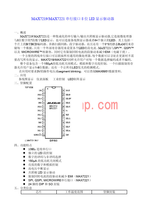
/MAX7221串行接口8位LED显示驱动器一、概述MAX7219/MAX7221是一种集成化的串行输入/输出共阴极显示驱动器,它连接微处理器与8位数字的7段数字LED显示,也可以连接条线图显示器或者64个独立的LED。
其上包括一个片上的B型BCD编码器、多路扫描回路,段字驱动器,而且还有一个8*8的静态RAM用来存储每一个数据。
只有一个外部寄存器用来设置各个LED的段电流。
MAX7221与SPI™、QSPI™以及MICROWIRE™相兼容,同时它有限制回转电流的段驱动来减少EMI(电磁干扰)。
一个方便的四线串行接口可以联接所有通用的微处理器。
每个数据可以寻址在更新时不需要改写所有的显示。
MAX7219/MAX7221同样允许用户对每一个数据选择编码或者不编码。
整个设备包含一个150μA的低功耗关闭模式,模拟和数字亮度控制,一个扫描限制寄存器允许用户显示1-8位数据,还有一个让所有LED发光的检测模式。
在应用时要求3V的操作电压或segment blinking,可以查阅MAX6951数据资料。
二、应用条线图显示仪表面板工业控制LED矩阵显示三、管脚配置四、功能特点●10MHz连续串行口●独立的LED段控制●数字的译码与非译码选择●150μA的低功耗关闭模式●亮度的数字和模拟控制●高电压中断显示●共阴极LED显示驱动●限制回转电流的段驱动来减少EMI(MAX7221)●SPI,QSPI,MICROWIRE串行接口(MAX7221)●24脚的DIP和SO封装五、分类信息芯片工作温度范围管脚封装MAX7219CNG0°C to+70°C24Narrow Plastic DIP MAX7219CWG0°C to+70°C24Wide SO MAX7219C/D0°C to+70°C Dice*MAX7219ENG-40°C to+85°C24Narrow Plastic DIP MAX7219EWG-40°C to+85°C24Wide SO MAX7219ERG-40°C to+85°C24Narrow CERDIP九、时序图十、详细描述(一)MAX7219和MAX7221的不同之处MAX7219和MAX7221是相同的除了以下两点:(1):MAX7219的段驱动有回流限制可以减少EMI;(2):MAX7219的串行口和SPI完全兼容。
国家质量监督检验检疫总局关于批准“碳钢成分分析标准物质”等214种国家一级和二级标准物质的通知

国家质量监督检验检疫总局关于批准“碳钢成分分析标准物质”等214种国家一级和二级标准物质的通知文章属性•【制定机关】国家质量监督检验检疫总局(已撤销)•【公布日期】2007.06.22•【文号】国质检量函[2007]478号•【施行日期】2007.06.22•【效力等级】部门规范性文件•【时效性】现行有效•【主题分类】质量监督检验检疫综合规定正文国家质量监督检验检疫总局关于批准“碳钢成分分析标准物质”等214种国家一级和二级标准物质的通知(2007年6月22日国质检量函[2007]478号)各省、自治区、直辖市质量技术监督局,国务院有关部门,各有关单位:根据《中华人民共和国计量法》和《标准物质管理办法》的有关规定,现批准“碳钢成分分析标准物质”等87种标准物质为国家一级标准物质,“氮中微量氧气体标准物质”等127种标准物质为国家二级标准物质(见附件1),列入中华人民共和国标准物质目录(见附件2),并统一编号,颁发“国家标准物质定级证书”和“制造计量器具许可证”。
国家煤炭质量监督检验中心新复制了煤物理特性和化学成分分析等标准物质,予以发布(见附件3)。
截至目前,我国共有国家一级标准物质1399种,国家二级标准物质2575种。
各有关单位要积极做好标准物质的推广、使用工作,加强对制造、销售和使用标准物质的监督管理。
附件1:国家标准物质项目表国家一级标准物质项目表┌───┬──────────┬───────┬───────┬────────────────────┬───────────────┐│ 序号│制造计量器具│标准物质│编号│标准物质名称│研制单位│││许可证号│定级证书号││││├───┼──────────┼───────┼───────┼────────────────────┼───────────────┤│1│││GBW 01229│碳钢成分分析标准物质│││2│││GBW 01230│合金钢成分分析标准物质│││3│││GBW 01231│合金钢成分分析标准物质│││4│││GBW 01232│合金钢成分分析标准物质│││5│││GBW 01233│合金钢成分分析标准物质│││6│││GBW 01234│合金钢成分分析标准物质│││7│││GBW 01235│合金钢成分分析标准物质│││││├───────┼────────────────────┤││8│││GBW 01236│碳钢光谱分析标准物质│山东省冶金科学研究院││9│││GBW 01237│合金钢光谱分析标准物质│││10│││GBW 01238│合金钢光谱分析标准物质│││11│││GBW 01239│合金钢光谱分析标准物质│││12│国制标物10000801│ 证字第0866│GBW 01240│合金钢光谱分析标准物质│││13│││GBW 01241│合金钢光谱分析标准物质│││14│││GBW 01242│合金钢光谱分析标准物质│││15││├───────┼────────────────────┤│││││GBW 01674│不锈钢成分分析标准物质│││16│││GBW 01675│不锈钢成分分析标准物质│││17│││GBW 01676│不锈钢成分分析标准物质│││18│││GBW 01677│耐热钢成分分析标准物质│││19│││GBW 01678│耐热钢成分分析标准物质│││20│││GBW 01679│耐热钢成分分析标准物质│││21│││GBW 01680│耐热钢成分分析标准物质│││22│││GBW 01681│耐热钢成分分析标准物质│││23│││GBW 01682│不锈钢光谱分析标准物质│││24│││GBW 01683│不锈钢光谱分析标准物质│││25│││GBW 01684│不锈钢光谱分析标准物质│││26│││GBW 01685│耐热钢光谱分析标准物质│││27│││GBW 01686│耐热钢光谱分析标准物质│││28│││GBW 01687│耐热钢光谱分析标准物质│││29│││GBW 01688│耐热钢光谱分析标准物质│││30│││GBW 01689│耐热钢光谱分析标准物质││├───┼──────────┼───────┼───────┼────────────────────┼───────────────┤│31│││GBW 04440│钕同位素丰度标准物质│││││├───────┼────────────────────┤││32│││GBW 06409│久效磷农药纯度标准物质│││33│││GBW 06410│水胺硫磷农药纯度标准物质│││34│国制标物10000802│证字第0867│GBW 06411│克线磷农药纯度标准物质│中国计量科学研究院││35│││GBW 06412│灭多威农药纯度标准物质│││36│││GBW 06413│双甲脒农药纯度标准物质│││37│││GBW 06414│噻嗪酮农药纯度标准物质│││38│││GBW 06415│联苯菊酯农药纯度标准物质│││39│││GBW 06416│氯菊酯农药纯度标准物质│││40│││GBW 06417│多效唑农药纯度标准物质││├───┼──────────┼───────┼───────┼────────────────────┼───────────────┤│41│││GBW 07343│黄河三角洲沉积物成分分析标准物质│青岛海洋地质研究所││42│ 国制标物10000803│证字第0868│GBW 07344│黄河三角洲沉积物成分分析标准物质│││43│││GBW 07345│黄河三角洲沉积物成分分析标准物质││├───┼──────────┼───────┼───────┼────────────────────┼───────────────┤│44│││GBW 07431│土壤、沉积物成分分析标准物质│││45│││GBW 07432│土壤、沉积物成分分析标准物质│││46│国制标物10000804│证字第0869│GBW 07433│土壤、沉积物成分分析标准物质│武汉综合岩矿测试中心││47│││GBW 07434│土壤、沉积物成分分析标准物质│││48│││GBW 07435│土壤、沉积物成分分析标准物质││├───┼──────────┼───────┼───────┼────────────────────┼───────────────┤│49│││GBW 07436│湖底沉积物重金属顺序提取形态标准物质│││50│国制标物10000805│证字第0870│GBW 07437│土壤重金属顺序提取形态标准物质│国家地质实验测试中心││51│││GBW 07438│黄土重金属顺序提取形态标准物质││├───┼──────────┼───────┼───────┼────────────────────┼───────────────┤│52│国制标物10000806│证字第0871│GBW 08520│烟草及卷烟中镉成分分析标准物质│浙江省医学科学院│├───┼──────────┼───────┼───────┼────────────────────┼───────────────┤│53│││GBW 08666│亚砷酸根溶液标准物质│││54│││GBW 08667│砷酸根溶液标准物质│││55│国制标物10000807│证字第0872│GBW 08668│一甲基砷溶液标准物质│中国计量科学研究院││56│││GBW 08669│二甲基砷溶液标准物质│││57│││GBW 08670│砷甜菜碱溶液标准物质│││58│││GBW 08671│砷胆碱溶液标准物质││├───┼──────────┼───────┼───────┼────────────────────┼───────────────┤│59│││GBW 08672│酸雨系列标准物质│国家环境保护总局标准样品研究所││60│国制标物10000808│证字第0873│GBW 08673│酸雨系列标准物质│、中国计量科学研究院││61│││GBW 08674│酸雨系列标准物质││├───┼──────────┼───────┼───────┼────────────────────┼───────────────┤│62│││GBW 08161│氮中苯、甲苯、乙苯、邻二甲苯、间二甲苯、│││││││对二甲苯、苯乙烯、乙酸丁酯、正己烷和十一│││││││烷混合气体标准物质│││63│││GBW 08162│氮中苯、甲苯、乙苯、邻二甲苯、间二甲苯、│││││││对二甲苯、苯乙烯、乙酸丁酯、正己烷和十一│││││││烷混合气体标准物质│││64│││GBW 08163│氮中苯、甲苯、乙苯、邻二甲苯、间二甲苯、│││││││对二甲苯、苯乙烯、乙酸丁酯、正己烷和十一│││││││烷混合气体标准物质│││││├───────┼────────────────────┤││65│││GBW 08164│氮中氟利昂F(22下标)气体标准物质│││66│││GBW 08165│氮中氟利昂F(22下标)气体标准物质│││67│国制标物10000809│证字第0874│GBW 08166│氮中氟利昂F(22下标)气体标准物质│││68│││GBW 08167│氮中氟利昂F(12下标)气体标准物质│││69│││GBW 08168│氮中氟利昂F(12下标)气体标准物质│││70│││GBW 08169│氮中氟利昂F(12下标)气体标准物质│中国计量科学研究院││71│││GBW 08170│氮中氯乙烯气体标准物质│││72│││GBW 08171│氮中氯乙烯气体标准物质│││73│││GBW 08172│氮中氯乙烯气体标准物质│││││├───────┼────────────────────┤││74│││GBW 08173│氮中四氟化碳气体标准物质│││75│││GBW 08174│空气中四氟化碳气体标准物质│││76│││GBW 08175│氮中六氟化硫气体标准物质│││77│││GBW 08176│空气中六氟化硫气体标准物质│││││├───────┼────────────────────┤││78│││GBW 08212│苯乙烯扩散管│││79│││GBW 08213│硝基苯扩散管│││80│││GBW 08214│氯苯扩散管│││81│││GBW 08215│正己烷扩散管│││82│││GBW 08216│十一烷扩散管││├───┼──────────┼───────┼───────┼────────────────────┼───────────────┤│83│││GBW 09150│乙型肝炎病毒脱氧核糖核酸血清标准物质││││国制标物10000810│证字第0875│││卫生部临床检验中心││84│││GBW 09151│丙型肝炎病毒核糖核酸血清标准物质││├───┼──────────┼───────┼───────┼────────────────────┼───────────────┤│85││证字第0876│GBW 12009│聚苯乙烯微球粒度标准物质│││86│国制标物10000811││GBW 12010│聚苯乙烯微球粒度标准物质│中国石油大学││87│││GBW 12011│聚苯乙烯微球粒度标准物质││└───┴──────────┴───────┴───────┴────────────────────┴───────────────┘国家二级标准物质项目表┌───┬───────────┬────────┬─────────┬──────────────────────┬──────────────┐│ 序号│制造计量器具│标准物质│编号│标准物质名称│研制单位│││许可证号│定级证书号││││├───┼───────────┼────────┼─────────┼──────────────────────┼──────────────┤│1│││GBW(E) 060757│氮中微量氧气体标准物质│││2│││GBW(E) 060758│氮中二氧化硫气体标准物质│││3│││GBW(E) 060759│氮中一氧化氮气体标准物质│││4│││GBW(E) 060760│氮中氧气体标准物质│││5│││GBW(E) 060761│氮中二氧化碳气体标准物质│保定市北方特种气体有限││6│国制标物10000812│证字第0877│GBW(E) 060762│氮中一氧化碳气体标准物质│公司││7│││GBW(E) 060763│空气中一氧化碳气体标准物质│││8│││GBW(E) 060764│空气中二氧化碳气体标准物质│││9│││GBW(E) 060765│空气中甲烷气体标准物质│││10│││GBW(E) 060766│空气中丙烷气体标准物质│││11│││GBW(E) 060767│氮中一氧化碳、二氧化碳和丙烷混合气体标准物质│││12│││GBW(E) 060768│氮中一氧化碳、二氧化碳、丙烷和一氧化氮混合气│││││││体标准物质││├───┼───────────┼────────┼─────────┼──────────────────────┼──────────────┤│13│││GBW(E) 060769│空气中甲烷气体标准物质│││14│国制标物10000813│证字第0878│GBW(E) 060770│氮中氧气体标准物质│││15│││GBW(E) 060771│氮中氢气体标准物质│济宁市协力气体厂││16│││GBW(E) 060772│空气中一氧化碳、二氧化碳、甲烷、乙炔、乙烯和│││││││乙烷混合气体标准物质││├───┼───────────┼────────┼─────────┼──────────────────────┼──────────────┤│17│││GBW(E) 060773│空气中甲烷气体标准物质│││18│国制标物10000814│证字第0879│GBW(E) 060774│空气中丙烷气体标准物质│无锡市光明特种气体有限││19│││GBW(E) 060775│空气中异丁烷气体标准物质│责任公司││20│││GBW(E) 060776│氮中氧气体标准物质││├───┼───────────┼────────┼─────────┼──────────────────────┼──────────────┤│21│││GBW(E) 060777│氮(空气)中二氧化碳气体标准物质│││22│││GBW(E) 060778│氮(空气)中异丁烷气体标准物质│││23│││GBW(E) 060779│氮中氧气体标准物质│││24│││GBW(E) 060780│氮(空气)中氢气体标准物质│中国兵器工业集团第五三││25│国制标物10000815│证字第0880│GBW(E) 060781│氮(空气)中乙炔气体标准物质│研究所││26│││GBW(E) 060782│氮(空气)中硫化氢气体标准物质│││27│││GBW(E) 060783│氮(空气)中苯气体标准物质│││28│││GBW(E) 060784│氮(空气)中甲苯气体标准物质│││29│││GBW(E) 060785│氮(空气)中丙烷、一氧化碳、二氧化碳和一氧化│││││││氮混合气体标准物质││├───┼───────────┼────────┼─────────┼──────────────────────┼──────────────┤│30│││GBW(E) 060786│氮中二氧化硫气体标准物质│││31│││GBW(E) 060787│氮中一氧化氮气体标准物质│││32│││GBW(E) 060788│氮中硫化氢气体标准物质│││33│││GBW(E) 060789│氮中异丁烷气体标准物质│││34│国制标物10000816│证字第0881│GBW(E) 060790│空气中氢气体标准物质│││35│││GBW(E) 060791│氩中甲烷气体标准物质│北京市北氧特种气体研究所有限││36│││GBW(E) 060792│氩中氢气体标准物质│公司││37│││GBW(E) 060793│氮中氧、氦和一氧化碳混合气体标准物质│││38│││GBW(E) 060794│氮中丙烷、一氧化氮、一氧化碳和二氧化碳混合气│││││││体标准物质││├───┼───────────┼────────┼─────────┼──────────────────────┼──────────────┤│39│││GBW(E) 060795│氮中二溴甲烷和氪混合气体标准物质│││40│││GBW(E) 060796│氮中二氧化硫气体标准物质│││41│││GBW(E) 060797│氮中硫化氢气体标准物质│││42│国制标物10000817│证字第0882│GBW(E) 060798│氮中六氟化硫气体标准物质│南京伟创气体有限公司││43│││GBW(E) 060799│氮中一氯二氟甲烷气体标准物质│││44│││GBW(E) 060800│氮中二氯二氟甲烷气体标准物质││├───┼───────────┼────────┼─────────┼──────────────────────┼──────────────┤│45│││GBW(E) 060801│空气(氮)中氢气体标准物质│││46│││GBW(E) 060802│空气(氮)中一氧化碳气体标准物质│││47│││GBW(E) 060803│空气(氮)中二氧化碳气体标准物质│││48│││GBW(E) 060804│空气(氮)中丙烷气体标准物质│││49│国制标物10000818│证字第0883│GBW(E) 060805│氮中一氧化碳、氧和氦混合气体标准物质│││50│││GBW(E) 060806│氢中氧、氮、一氧化碳、二氧化碳和甲烷混合气体│北京海谱气体有限公司││││││标准物质│││51│││GBW(E) 060807│氮中甲烷、乙烷、丙烷、正丁烷、异丁烷、正戊烷│││││││、异戊烷、正已烷和二氧化碳混合气体标准物质│││52│││GBW(E) 060808│氮中氢、氧、氦、一氧化碳、二氧化碳、甲烷、乙│││││││烷、乙烯和乙炔气体标准物质││├───┼───────────┼────────┼─────────┼──────────────────────┼──────────────┤│53│││GBW(E) 060809│空气中甲烷气体标准物质│││54│国制标物10000819│证字第0884│GBW(E) 060810│氮中氧气体标准物质│上海海洲特种气体有限公司││55│││GBW(E) 060811│氦中氢气体标准物质│││56│││GBW(E) 060812│氮中一氧化碳和二氧化碳混合气体标准物质││├───┼───────────┼────────┼─────────┼──────────────────────┼──────────────┤│57│││GBW(E) 081029│氢氧化钠滴定溶液标准物质│││58│││GBW(E) 081030│氢氧化钠滴定溶液标准物质│││59│││GBW(E) 081031│氢氧化钠滴定溶液标准物质│││60│││GBW(E) 081032│盐酸滴定溶液标准物质│││61│国制标物10000820│证字第0885│GBW(E) 081033│盐酸滴定溶液标准物质│││62│││GBW(E) 081034│盐酸滴定溶液标准物质│││63│││GBW(E) 081035│硫酸滴定溶液标准物质│││64│││GBW(E) 081036│硫酸滴定溶液标准物质│││65│││GBW(E) 081037│硫酸滴定溶液标准物质│││66│││GBW(E) 081038│重铬酸钾滴定溶液标准物质│││67│││GBW(E) 081039│碘酸钾滴定溶液标准物质│││68│││GBW(E) 081040│碘酸钾滴定溶液标准物质│上海化学试剂研究所││69│││GBW(E) 081041│乙二胺四乙酸二钠滴定溶液标准物质│││70│││GBW(E) 081042│乙二胺四乙酸二钠滴定溶液标准物质│││71│││GBW(E) 081043│乙二胺四乙酸二钠滴定溶液标准物质│││72│││GBW(E) 081044│氯化钠滴定溶液标准物质│││73│││GBW(E) 081045│硫氰酸钠滴定溶液标准物质│││74│││GBW(E) 081046│硝酸银滴定溶液标准物质││├───┼───────────┼────────┼─────────┼──────────────────────┼──────────────┤│75│││GBW(E) 081047│硝基苯溶液标准物质│││76│││GBW(E) 081048│对硝基甲苯溶液标准物质│││77│││GBW(E) 081049│对硝基氯苯溶液标准物质│││78│││GBW(E)081050│2,4--二硝基甲苯溶液标准物质│││79│││GBW(E)081051│2,4--二硝基氯苯溶液标准物质│││80│││GBW(E)081052│2,4,6--三硝基甲苯溶液标准物质│││81│││GBW(E) 081053│硝基苯类混合溶液标准物质│││82│││GBW(E) 081054│甲醇中二氯甲烷溶液标准物质│中国计量科学研究院││83│国制标物10000821│证字第0886│GBW(E) 081055│甲醇中1,1--二氯乙烷溶液标准物质│││84│││GBW(E) 081056│甲醇中1,2--二氯乙烷溶液标准物质│││85│││GBW(E) 081057│甲醇中一溴二氯甲烷溶液标准物质│││86│││GBW(E) 081058│甲醇中二溴一氯甲烷溶液标准物质│││87│││GBW(E) 081059│甲醇中三氯乙烯溶液标准物质│││88│││GBW(E) 081060│甲醇中四氯乙烯溶液标准物质│││89│││GBW(E) 081061│甲醇中反--1,2--二氯乙烯溶液标准物质│││90│││GBW(E) 081062│甲醇中顺--1,2--二氯乙烯溶液标准物质│││91│││GBW(E) 081063│甲醇中二氯甲烷、1,1--二氯乙烷、1,2--│││││││二氯乙烷、三氯乙烯、四氯乙烷、一溴二氯甲烷│││││││、二溴一氯甲烷、反--1,2--二氯乙烯混合溶│││││││液标准物质││├───┼───────────┼────────┼─────────┼──────────────────────┼──────────────┤│92│国制标物10000822│证字第0887│GBW(E) 090053│可见异物微粒标准物质│北京海岸鸿蒙标准物质技术有限│││││││责任公司│├───┼───────────┼────────┼─────────┼──────────────────────┼──────────────┤│93│国制标物10000823│证字第0888│GBW(E) 090054│牛血铅(络合型)成分分析标准物质│新探健康发展研究中心、西安市││94│││GBW(E) 090055│牛血铅(络合型)成分分析标准物质│中心医院││95│││GBW(E) 090056│牛血铅(络合型)成分分析标准物质││├───┼───────────┼────────┼─────────┼──────────────────────┼──────────────┤│96│││GBW(E) 100050│苏氨酸纯度标准物质│││97│││GBW(E) 100051│丝氨酸纯度标准物质│││98│││GBW(E) 100052│谷氨酸纯度标准物质│││99│││GBW(E) 100053│甘氨酸纯度标准物质│││ 100│││GBW(E) 100054│丙氨酸纯度标准物质│││ 101│││GBW(E) 100055│缬氨酸纯度标准物质│││ 102│国制标物10000824│证字第0889│GBW(E) 100056│甲硫氨酸纯度标准物质│中国计量科学研究院││ 103│││GBW(E) 100057│异亮氨酸纯度标准物质│││ 104│││GBW(E) 100058│亮氨酸纯度标准物质│││ 105│││GBW(E) 100059│酪氨酸纯度标准物质│││ 106│││GBW(E) 100060│盐酸赖氨酸纯度标准物质│││ 107│││GBW(E) 100061│苯丙氨酸纯度标准物质│││ 108│││GBW(E) 100062│氨基酸混合溶液标准物质││├───┼───────────┼────────┼─────────┼──────────────────────┼──────────────┤│ 109│││GBW(E) 100063│食品添加剂咖啡因纯度标准物质│││ 110│国制标物10000825│证字第0890│GBW(E) 100064│食品添加剂对羟基苯甲酸乙酯纯度标准物质│││ 111│││GBW(E) 100065│食品添加剂安赛蜜纯度标准物质│中国计量科学研究院││ 112│││GBW(E) 100066│食品添加剂甜蜜素纯度标准物质││├───┼───────────┼────────┼─────────┼──────────────────────┼──────────────┤│ 113│││GBW(E) 120037│微粒标准物质│││ 114│││GBW(E) 120038│微粒标准物质│││ 115│││GBW(E) 120039│微粒标准物质│││ 116│││GBW(E) 120040│微粒标准物质│││ 117│││GBW(E) 120041│微粒标准物质│││ 118│││GBW(E) 120042│微粒标准物质│││ 119│││GBW(E) 120043│微粒标准物质│北京海岸鸿蒙标准物质技术有限││ 120│国制标物10000826│证字第0891│GBW(E) 120044│微粒标准物质│责任公司││ 121│││GBW(E) 120045│微粒标准物质│││ 122│││GBW(E) 120046│微粒标准物质│││ 123│││GBW(E) 120047│微粒标准物质│││ 124│││GBW(E) 120048│微粒标准物质│││ 125│││GBW(E) 120049│微粒标准物质│││ 126│││GBW(E) 120050│微粒标准物质│││ 127│││GBW(E) 120051│微粒标准物质││└───┴───────────┴────────┴─────────┴──────────────────────┴──────────────┘附件2:┌────────────────────────────────────────┐│││中华人民共和国标准物质目录││(新发布部分)││││││││国家质量监督检验检疫总局││中国北京││(2007年6月)│││└────────────────────────────────────────┘┌────────────┬──────┬──────┬─────────────────────────────────────────────────┐│名称│编号│标准值及标准│质量分数(×(10的-2次方))││││偏差││├────────────┼──────┼──────┼────┬────┬────┬────┬────┬────┬────┬────┬────┬────┤││││ C│Si│ Mn│ P│ S│ Cr│ Ni│ Mo│ V│ Al (s) │││├──────┼────┼────┼────┼────┼────┼────┼────┼────┼────┼────┤│碳钢成分分析标准物质│ GBW 01229│标准值│ 0.162│ 0.210│ 0.373│ 0.019│ 0.015│ 0.129│ 0.136│ 0.024│ 0.0011 │ 0.0018 │││├──────┼────┼────┼────┼────┼────┼────┼────┼────┼────┼────┤│││标准偏差(s) │ 0.002│0.004│ 0.003│ 0.001│ 0.001│ 0.003│ 0.004│ 0.002│0.0003 │ 0.0005 │├────────────┼──────┼──────┼────┼────┼────┼────┼────┼────┼────┼────┼────┼────┤││ GBW 01230│标准值│ 0.345│ 0.318│ 0.424│ 0.022│ 0.011│ 1.58│ 0.099│ 0.171│ 0.0034 │ 0.803│││├──────┼────┼────┼────┼────┼────┼────┼────┼────┼────┼────┤│││标准偏差(s) │ 0.006│ 0.007│ 0.004│ 0.001│ 0.001│0.01│ 0.002│ 0.003│ 0.0002 │ 0.005││├──────┼──────┼────┼────┼────┼────┼────┼────┼────┼────┼────┼────┤││ GBW 01231│标准值│ 0.210│ 0.385│ 1.30│ 0.013│ 0.021│ 0.169│ 0.099│ 0.015│0.011│ 0.054│││├──────┼────┼────┼────┼────┼────┼────┼────┼────┼────┼────┤│││标准偏差(s) │ 0.004│0.006│0.01│ 0.001│ 0.001│ 0.004│ 0.001│ 0.001│ 0.001│ 0.002││├──────┼──────┼────┼────┼────┼────┼────┼────┼────┼────┼────┼────┤│合金钢成分分析标准物质│ GBW 01232│标准值│ 0.118│ 0.236│ 0.257│ 0.023│ 0.023│ 0.147│ 0.154│ 0.020│ 0.0023 │ 0.101│││├──────┼────┼────┼────┼────┼────┼────┼────┼────┼────┼────┤│││标准偏差(s) │ 0.003│0.005│ 0.003│ 0.001│ 0.001│ 0.003│ 0.004│ 0.001│ 0.0001 │ 0.004││├──────┼──────┼────┼────┼────┼────┼────┼────┼────┼────┼────┼────┤││ GBW 01233│标准值│ 0.397│1.00│ 0.701│ 0.013│ 0.012│ 1.91│ 1.29│ 0.446│ 0.377│ 0.010│││├──────┼────┼────┼────┼────┼────┼────┼────┼────┼────┼────┤│││标准偏差(s) │ 0.005│0.03│ 0.009│ 0.001│ 0.001│0.02│0.02│ 0.009│ 0.005│ 0.002││├──────┼──────┼────┼────┼────┼────┼────┼────┼────┼────┼────┼────┤││ GBW 01234│标准值│ 0.249│ 0.464│ 0.444│ 0.016│ 0.021│ 1.64│ 1.73│ 0.426│ 0.218│ 0.0042 │││├──────┼────┼────┼────┼────┼────┼────┼────┼────┼────┼────┤│││标准偏差(s) │ 0.004│ 0.004│ 0.008│ 0.001│ 0.001│0.02│0.02│ 0.004│ 0.004│ 0.0003 ││├──────┼──────┼────┼────┼────┼────┼────┼────┼────┼────┼────┼────┤││ GBW 01235│标准值│ 0.384│ 0.862│ 0.583│ 0.014│ 0.012│ 2.06│ 1.32│ 0.382│ 0.350│ 0.014│││├──────┼────┼────┼────┼────┼────┼────┼────┼────┼────┼────┤│││标准偏差(s) │ 0.006│ 0.009│ 0.006│ 0.001│ 0.001│0.02│0.02│ 0.004│ 0.007│ 0.001│├────────────┼──────┼──────┼────┼────┼────┼────┼────┼────┼─。
1123721-1中文资料
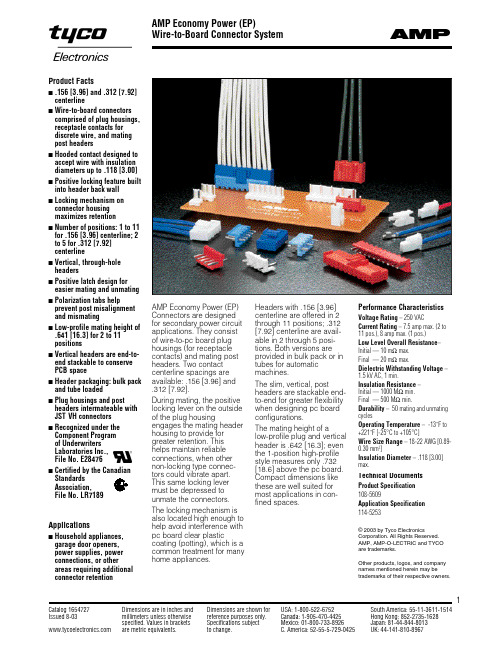
AMP Economy Power (EP)Wire-to-Board Connector System1Product Factss.156 [3.96] and .312 [7.92]centerlines Wire-to-board connectors comprised of plug housings,receptacle contacts for discrete wire, and mating post headerss Hooded contact designed to accept wire with insulation diameters up to .118 [3.00]s Positive locking feature built into header back wall s Locking mechanism on connector housing maximizes retentions Number of positions: 1 to 11for .156 [3.96] centerline; 2to 5 for .312 [7.92]centerlines Vertical, through-hole headerss Positive latch design for easier mating and unmating s Polarization tabs help prevent post misalignment and mismatings Low-profile mating height of .641 [16.3] for 2 to 11positionss Vertical headers are end-to-end stackable to conserve PCB spaces Header packaging: bulk pack and tube loadeds Plug housings and post headers intermateable with JST VH connectors s Recognized under the Component Program of Underwriters Laboratories Inc.,File No. E28476s Certified by the Canadian Standards Association,File No. LR7189AMP Economy Power (EP)Connectors are designed for secondary power circuit applications. They consist of wire-to-pc board plug housings (for receptacle contacts) and mating post headers. Two contact centerline spacings are available: .156 [3.96] and .312 [7.92].During mating, the positive locking lever on the outside of the plug housingengages the mating header housing to provide for greater retention. This helps maintain reliable connections, when other non-locking type connec-tors could vibrate apart.This same locking lever must be depressed to unmate the connectors. The locking mechanism is also located high enough to help avoid interference with pc board clear plasticcoating (potting), which is a common treatment for many home appliances.Headers with .156 [3.96]centerline are offered in 2through 11 positions; .312[7.92] centerline are avail-able in 2 through 5 posi-tions. Both versions are provided in bulk pack or in tubes for automatic machines.The slim, vertical, postheaders are stackable end-to-end for greater flexibility when designing pc board configurations.The mating height of alow-profile plug and vertical header is .642 [16.3]; even the 1-position high-profile style measures only .732[18.6] above the pc pact dimensions like these are well suited for most applications in con-fined spaces.Technical DocumentsProduct Specification 108-5609Application Specification 114-5253© 2003 by Tyco ElectronicsCorporation. All Rights Reserved.AMP, AMP-O-LECTRIC and TYCO are trademarks.Other products, logos, and company names mentioned herein may betrademarks of their respective owners.Performance CharacteristicsVoltage Rating – 250 VACCurrent Rating – 7.5 amp max. (2 to 11 pos.), 8 amp max. (1 pos.)Low Level Overall Resistance –Initial — 10 m Ωmax.Final — 20 m Ωmax.Dielectric Withstanding Voltage –1.5 kV AC, 1 min.Insulation Resistance – Initial — 1000 M Ωmin.Final — 500 M Ωmin.Durability – 50 mating and unmating cyclesOperating Temperature – -13˚F to +221˚F [-25°C to +105°C]Wire Size Range – 18-22 AWG [0.89-0.30 mm 2]Insulation Diameter – .118 [3.00]max.ApplicationssHousehold appliances,garage door openers, power supplies, power connections, or other areas requiring additional connector retentionContacts and Plug Housings, Low-ProfileCrimp, Snap-inReceptacle ContactsMaterial and FinishSee chart.Related Product DataPlug Housings—Pages 2 and 4:2Plug HousingsMaterial and FinishHousing —UL 94V-0 rated nylon, natural colorNote: Alternate colors available upon request. Minimums may apply. Please contact product engineer or product manager for details.Related Product DataContacts —see aboveMating Post Headers —Page 3PositionsANumber 2.310[ 7.86]1-1123722-23.465 [11.82]1-1123722-34.621 [15.78]1-1123722-45.777 [19.74]1-1123722-56.933[23.70]1-1123722-67 1.089[27.66]1-1123722-78 1.245[31.62]1-1123722-89 1.401[35.58]1-1123722-910 1.557[39.54]1-1123722-011 1.713 [43.50]1-1123722-1Applicator Part NumberWire Size WireMaterial Part AMPOMATORCLS AMP-O-LECTRIC Terminator Range Insulation and Number IV+ Lead Maker Model K Model G AWG mm 2Diameter Finish(Strip Form)Base Part No.Part No.Part No.3565001-471273-3354500-118-220.89-0.30.067-.118Phos. Brz.,1123721-11385286-11385286-21385286-31.70-3.00Pre-Tin Brass,1123721-2Pre-TinVertical Post Headers, Low-Profile.156 [3.96] CenterlineMaterial and FinishHousing —UL 94V-0 rated nylon, natural colorNote: Alternate colors available upon request. Minimums may apply. Please contact product engineer or product manager for details.Post —Tin-plated brassRelated Product DataMating Plug Housings —Page 2.312 [7.92] CenterlineMaterial and FinishHousing —UL 94V-0 rated nylon, natural colorNote: Alternate colors available upon request. Minimums may apply. Please contact product engineer or product manager for details.Post —Tin-plated brassRelated Product DataMating Plug Housings —Page 23Number of DimensionPart NumberPositionsABulk Pack Tube Loaded (Pcs. per Tube)2.310[ 7.86]1-1123723-21-1318300-2 (61)3.465 [11.82]1-1123723-31-1318300-3 (40)4.621 [15.78]1-1123723-41-1318300-4 (30)5.777 [19.74]1-1123723-51-1318300-5 (24)6.933[23.70]1-1123723-61-1318300-6 (20)7 1.089[27.66]1-1123723-71-1318300-7 (17)8 1.245[31.62]1-1123723-81-1318300-8 (15)9 1.401[35.58]1-1123723-91-1318300-9 (13)10 1.557[39.54]1-1123723-01-1318300-0 (12)111.713 [43.50]1-1123723-11-1318300-1 (11)Part NumberPositionsA Bulk Pack Tube Loaded (Pcs. per Tube)2.465 [11.82]1-1123724-21-1318301-2 (40)3.777 [19.74]1-1123724-31-1318301-3 (24)4 1.089 [27.66]1-1123724-41-1318301-4 (17)5 1.401[35.58]1-1123724-51-1318301-5 (13)Mating Height(Low Profile)Plug Housing and Post Header, High Profile1 Position Plug HousingPart Number 1-1123823-1Material and FinishHousing—UL 94V-0 rated nylon,natural colorNote: Alternate colors available uponrequest. Minimums may apply. Pleasecontact product engineer or productmanager for details.Related Product DataContacts—Page 2Mating Post Header—See below41 Position Post Header, VerticalPart Numbers1-1123824-1 (Bulk Pack)1-1318831-1 (Tube Loaded, 55 pcs. per Tube)Material and Finish Housing—UL 94V-0 rated nylon, natural colorNote: Alternate colors available upon request. Minimums may apply. Please contact product engineer or product manager for details.Post—Tin-plated brassRelated Product DataMating Plug Housing—See aboveMating Height(High Profile)。
TM7221资料
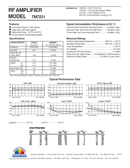
2.0 1.5 1.0
Input VSWR
2.0 1.5 1.0
Output VSWR
Start 20 MHz
Stop 200 MHz
Start 20 MHz
Stop 200 MHz
Start 20 MHz
Stop 200 MHz
Legend
+ 25 ºC
+ 85 ºC - - - - - - -55 ºC
Specifications
CHARACTERISTIC Frequency Gain (dB) Power @ 1 dB Comp. (dBm) Reverse Isolation (dB) VSWR In Out TYPICAL Ta= 25 ºC 20-200 MHz 28.5 +18.5 -31.5 <1.5:1 <1.4:1 2.0 +15 29 MIN/MAX Ta = -55 ºC to +85 ºC 20-200 MHz 27.0 Min. +15 Min. -30 Max 2.0:1 Max. 2.0:1 Max. 3.0 Max. +15 Min. 32 Max.
Spectrum Microwave · 2144 Franklin Drive N.E. · Palm Bay, Florida 32905 · PH (888) 553-7531 · Fax (888) 553-7532
6/29/04
Spectrum Microwave (Europe) · 2707 Black Lake Place · Philadelphia, Pa. 19154 · PH (215) 464-4000 · Fax (215) 464-4001
ISO7221CQDRQ1,ISO7221CQDRQ1,ISO7221CQDRQ1, 规格书,Datasheet 资料
ISO7220A-Q1ISO7221A-Q1ISO7221C-Q1 SLLS965C–JULY2009–REVISED MAY2012DUAL DIGITAL ISOLATORSCheck for Samples:ISO7220A-Q1,ISO7221A-Q1,ISO7221C-Q1FEATURES•Qualified for Automotive Applications•4000-V peak Isolation,560V peak V IORM•1-Mbps and25-Mbps Signaling Rate Options–UL1577,IEC60747-5-2(VDE0884,Rev2),IEC61010-1,IEC60950-1and CSA –Low Channel-to-Channel Output Skew:Approved1ns(Max)–50kV/μs Typical Transient Immunity –Low Pulse-Width Distortion(PWD):1ns(Max)•Operates with3.3-V or5-V Supplies –Low Jitter Content:1ns(Typ)at150Mbps•4kV ESD Protection•25-Year(Typ)Life at Rated Voltage•High Electromagnetic Immunity (See Application Report SLLA197and•–40°C to125°C Operating Free-AirFigure14)Temperature RangeDESCRIPTIONThe ISO7220and ISO7221are dual-channel digital isolators.To facilitate PCB layout,the channels are oriented in the same direction in the ISO7220and in opposite directions in the ISO7221.These devices have a logic input and output buffer separated by TI’s silicon-dioxide(SiO2)isolation barrier,providing galvanic isolation of up to ed in conjunction with isolated power supplies,these devices block high voltage,isolate grounds,and prevent noise currents on a data bus or other circuits from entering the local ground and interfering with or damaging sensitive circuitry.A binary input signal is conditioned,translated to a balanced signal,then differentiated by the capacitive isolation barrier.Across the isolation barrier,a differential comparator receives the logic transition information,then sets or resets a flip-flop and the output circuit accordingly.A periodic update pulse is sent across the barrier to ensure the proper dc level of the output.If this dc-refresh pulse is not received every4μs,the input is assumed to be unpowered or not being actively driven,and the failsafe circuit drives the output to a logic high state.The small capacitance and resulting time constant provide fast operation with signaling rates available from0 Mbps(dc)to25Mbps.(1)The A-option and C-option devices have TTL input thresholds and a noise filter at the input that prevents transient pulses from being passed to the output of the device.These devices require two supply voltages of3.3V,5V,or any combination.All inputs are5-V tolerant when supplied from a3.3-V supply and all outputs are4-mA CMOS.These devices are characterized for operation over the ambient temperature range of–40°C to125°C.(1)The signaling rate of a line is the number of voltage transitions that are made per second expressed in the units bps(bits per second).Please be aware that an important notice concerning availability,standard warranty,and use in critical applications ofTexas Instruments semiconductor products and disclaimers thereto appears at the end of this data sheet.PRODUCTION DATA information is current as of publication date.Copyright©2009–2012,Texas Instruments Incorporated Products conform to specifications per the terms of the TexasGalvanic IsolationBarrierISO7221GND2INB V CC2V CC1OUTB GND1INA OUTA ISO7220GND2INB V CC2V CC1OUTB GND1OUTA INA ISO7220A-Q1ISO7221A-Q1ISO7221C-Q1SLLS965C –JULY 2009–REVISED MAY 2012This integrated circuit can be damaged by ESD.Texas Instruments recommends that all integrated circuits be handled with appropriate precautions.Failure to observe proper handling and installation procedures can cause damage.ESD damage can range from subtle performance degradation to complete device failure.Precision integrated circuits may be more susceptible to damage because very small parametric changes could cause the device not to meet its published specifications.ORDERING INFORMATION (1)SIGNALING T APACKAGE (2)ORDERABLE PART NUMBER TOP-SIDE MARKING RATE 1MbpsSOIC –D Reel of 2500ISO7220AQDRQ17220AQ –40°C to 125°C1Mbps SOIC –D Reel of 2500ISO7221AQDRQ17221AQ 25MbpsSOIC –DReel of 2500ISO7221CQDRQ17221CQ(1)For the most current package and ordering information,see the Package Option Addendum at the end of this document,or see the TI web site at .(2)Package drawings,thermal data,and symbolization are available at /packaging .SINGLE-CHANNEL FUNCTION DIAGRAMREGULATORY INFORMATIONVDECSAULApproved under CSA Component Recognized under 1577Component Certified according to IEC 60747-5-2Acceptance Notice Recognition Program (1)File Number:40016131File Number:1698195File Number:E181974(1)Production tested ≥3000VRMS for 1second in accordance with UL 1577.2Submit Documentation Feedback Copyright ©2009–2012,Texas Instruments IncorporatedISO7220A-Q1ISO7221A-Q1ISO7221C-Q1 SLLS965C–JULY2009–REVISED MAY2012 ABSOLUTE MAXIMUM RATINGS(1)V CC Supply voltage(2),V CC1,V CC2–0.5V to6VV I Voltage at IN,OUT–0.5V to6VI O Output current±15mAHuman-Body Model±4kV ElectrostaticESD Field-Induced Charged-Device Model All pins±1kV dischargeMachine Model±200VT J Maximum junction temperature150°CT stg Storage temperature–65°C to150°C (1)Stresses beyond those listed under absolute maximum ratings may cause permanent damage to the device.These are stress ratingsonly and functional operation of the device at these or any other conditions beyond those indicated under recommended operating conditions is not implied.Exposure to absolute-maximum-rated conditions for extended periods may affect device reliability.(2)All voltage values except differential I/O bus voltages are with respect to network ground terminal and are peak voltage values. RECOMMENDED OPERATING CONDITIONSMIN TYP MAX UNIT V CC Supply voltage(1)V CC1,V CC23 5.5VI OH High-level output current4mAI OL Low-level output current–4mAISO722xA10.67μst ui Input pulse widthISO722xC4033nsISO722xA015001000kbps 1/t ui Signaling rateISO722xC03025Mbps V IH High-level input voltage2V CC VV IL Low-level input voltage00.8VT J Operating virtual-junction temperature–40150°CH External magnetic field-strength immunity per IEC61000-4-8and IEC61000-4-9certification1000A/m(1)For the5-V operation,V CC1or V CC2is specified from4.5V to5.5V.For the3-V operation,V CC1or V CC2is specified from3V to3.6V.Copyright©2009–2012,Texas Instruments Incorporated Submit Documentation Feedback3ISO7220A-Q1ISO7221A-Q1ISO7221C-Q1SLLS965C–JULY2009–REVISED ELECTRICAL CHARACTERISTICSV CC1and V CC2at5V(1),over recommended operating conditions(unless otherwise noted)PARAMETER TEST CONDITIONS MIN TYP MAX UNITISO7220x12QuiescentISO7221x8.517I CC1Supply current,V CC1ISO7220A V I=V CC or0V,no load23mA1MbpsISO7221A1018ISO7221C25Mbps1222ISO7220x1631QuiescentISO7221x8.517I CC2Supply current,V CC2ISO7220A V I=V CC or0V,no load1732mA1MbpsISO7221A1018ISO7221C25Mbps1222I OH=–4mA,See Figure1V CC–0.8 4.6V OH High-level output voltage VI OH=–20μA,See Figure1V CC–0.15I OL=4mA,See Figure10.20.4V OL Low-level output voltage VI OL=20μA,See Figure100.1V I(HYS)Input voltage hysteresis150mVI IH High-level input current IN from0V to V CC10μAI IL Low-level input current IN from0V to V CC–10μAC I Input capacitance to ground IN at V CC,V I=0.4sin(4E6πt)1pF CMTI Common-mode transient immunity V I=V CC or0V,See Figure32550kV/μs (1)For the5-V operation,V CC1or V CC2is specified from4.5V to5.5V.For the3-V operation,V CC1or V CC2is specified from3V to3.6V.SWITCHING CHARACTERISTICSV CC1=V CC2=5V,over recommended operating conditions(unless otherwise noted)PARAMETER TEST CONDITIONS MIN TYP MAX UNIT t pLH,t pHL Propagation delay280405480nsISO722xA See Figure1PWD Pulse-width distortion|t pHL–t pLH|(1)114nst pLH,t pHL Propagation delay223242nsISO722xC See Figure1PWD Pulse-width distortion|t pHL–t pLH|(1)12nsISO722xA180t sk(pp)Part-to-part skew(2)nsISO722xC10ISO722xA315t sk(o)Channel-to-channel output skew(3)nsISO722xC0.21t r Output signal rise time See Figure11nst f Output signal fall time See Figure11nst fs Failsafe output delay time from input power loss See Figure23μs(1)Also referred to as pulse skew.(2)t sk(pp)is the magnitude of the difference in propagation delay times between any specified terminals of two devices when both devicesoperate with the same supply voltages,at the same temperature,and have identical packages and test circuits.(3)t sk(o)is the skew between specified outputs of a single device with all driving inputs connected together and the outputs switching in thesame direction while driving identical specified loads.4Submit Documentation Feedback Copyright©2009–2012,Texas Instruments IncorporatedISO7220A-Q1ISO7221A-Q1ISO7221C-Q1 SLLS965C–JULY2009–REVISED MAY2012 ELECTRICAL CHARACTERISTICSV CC1=5V,V CC2=3.3V(1),over recommended operating conditions(unless otherwise noted)PARAMETER TEST CONDITIONS MIN TYP MAX UNITISO7220x12Quiescent V I=V CC or0V,no loadISO7221x8.517I CC1Supply current,V CC1ISO7220A23mA1Mbps V I=V CC or0V,no loadISO7221A1018ISO7221C25Mbps V I=V CC or0V,no load1222ISO7220x818Quiescent V I=V CC or0V,no loadISO7221x 4.39.5I CC2Supply current,V CC2ISO7220A919mA1Mbps V I=V CC or0V,no loadISO7221A511ISO7221C25Mbps V I=V CC or0V,no load612ISO7220x V CC–0.4I OH=–4mA,See Figure1ISO7221xV OH High-level output voltage V CC–0.8V(5-V side)I OH=–20μA,See Figure1V CC–0.1I OL=4mA,See Figure10.4V OL Low-level output voltage VI OL=20μA,See Figure10.1V I(HYS)Input voltage hysteresis150mVI IH High-level input current IN from0V to V CC10μAI IL Low-level input current IN from0V to V CC–10μAC I Input capacitance to ground IN at V CC,V I=0.4sin(4E6πt)1pF CMTI Common-mode transient immunity V I=V CC or0V,See Figure31540kV/μs (1)For the5-V operation,V CC1or V CC2is specified from4.5V to5.5V.For the3-V operation,V CC1or V CC2is specified from3V to3.6V.SWITCHING CHARACTERISTICSV CC1=5V,V CC2=3.3V,over recommended operating conditions(unless otherwise noted)PARAMETER TEST CONDITIONS MIN TYP MAX UNIT t pLH,t pHL Propagation delay285410480nsISO722xA See Figure1PWD Pulse-width distortion|t pHL–t pLH|(1)114nst pLH,t pHL Propagation delay253648nsISO722xC See Figure1PWD Pulse-width distortion|t pHL–t pLH|(1)12nsISO722xA180t sk(pp)Part-to-part skew(2)nsISO722xC10ISO722xA315t sk(o)Channel-to-channel output skew(3)nsISO722xC0.21t r Output signal rise time See Figure12nst f Output signal fall time See Figure12t fs Failsafe output delay time from input power loss See Figure23μs(1)Also referred to as pulse skew.(2)t sk(pp)is the magnitude of the difference in propagation delay times between any specified terminals of two devices when both devicesoperate with the same supply voltages,at the same temperature,and have identical packages and test circuits.(3)t sk(o)is the skew between specified outputs of a single device with all driving inputs connected together and the outputs switching in thesame direction while driving identical specified loads.Copyright©2009–2012,Texas Instruments Incorporated Submit Documentation Feedback5ISO7220A-Q1ISO7221A-Q1ISO7221C-Q1SLLS965C–JULY2009–REVISED ELECTRICAL CHARACTERISTICSV CC1=3.3V,V CC2=5V(1),over recommended operating conditions(unless otherwise noted)PARAMETER TEST CONDITIONS MIN TYP MAX UNITISO7220x0.61QuiescentISO7221x 4.39.5I CC1Supply current,V CC1ISO7220A V I=V CC or0V,no load12mA1MbpsISO7221A511ISO7221C25Mbps612ISO7220x1631QuiescentISO7221x8.517I CC2Supply current,V CC2ISO7220A V I=V CC or0V,no load1832mA1MbpsISO7221A1018ISO7221C25Mbps1222ISO7220x V CC–0.8I OH=–4mA,See Figure1ISO7221xV OH High-level output voltage V CC–0.4V(3.3-V side)I OH=–20μA,See Figure1V CC–0.1IOL=4mA,See Figure10.4V OL Low-level output voltage VIOL=20μA,See Figure100.1V I(HYS)Input threshold voltage hysteresis150mVI IH High-level input current IN from0V or V CC10μAI IL Low-level input current IN from0V or V CC–10μAC I Input capacitance to ground IN at V CC,V I=0.4sin(4E6πt)1pF CMTI Common-mode transient immunity V I=V CC or0V,See Figure31540kV/μs (1)For the5-V operation,V CC1or V CC2is specified from4.5V to5.5V.For the3-V operation,V CC1or V CC2is specified from3V to3.6V.SWITCHING CHARACTERISTICSV CC1=3.3V,V CC2=5V,over recommended operating conditions(unless otherwise noted)PARAMETER TEST CONDITIONS MIN TYP MAX UNIT t pLH,t pHL Propagation delay285395480nsISO722xA See Figure1PWD Pulse-width distortion|t pHL–t pLH|(1)118nst pLH,t pHL Propagation delay243648nsISO722xC See Figure1PWD Pulse-width distortion|t pHL–t pLH|(1)13nsISO722xA190t sk(pp)Part-to-part skew(2)nsISO722xC10ISO722xA315t sk(o)Channel-to-channel output skew(3)nsISO722xC0.21t r Output signal rise time See Figure11nst f Output signal fall time See Figure11nst fs Failsafe output delay time from input power loss See Figure23μs(1)Also referred to as pulse skew.(2)t sk(pp)is the magnitude of the difference in propagation delay times between any specified terminals of two devices when both devicesoperate with the same supply voltages,at the same temperature,and have identical packages and test circuits.(3)t sk(o)is the skew between specified outputs of a single device with all driving inputs connected together and the outputs switching in thesame direction while driving identical specified loads.6Submit Documentation Feedback Copyright©2009–2012,Texas Instruments IncorporatedISO7220A-Q1ISO7221A-Q1ISO7221C-Q1 SLLS965C–JULY2009–REVISED MAY2012 ELECTRICAL CHARACTERISTICSV CC1=V CC2=3.3V(1),over recommended operating conditions(unless otherwise noted)PARAMETER TEST CONDITIONS MIN TYP MAX UNITISO7220x0.61QuiescentISO7221x 4.39.5I CC1Supply current,V CC1ISO7220A V I=V CC or0V,no load12mA1MbpsISO7221A511ISO7221C25Mbps612ISO7220x818QuiescentISO7221x 4.39.5I CC2Supply current,V CC2ISO7220A V I=V CC or0V,no load919mA1MbpsISO7221A511ISO7221C25Mbps612I OH=–4mA,See Figure1V CC–0.43V OH High-level output voltage VI OH=–20μA,See Figure1V CC–0.1 3.3I OL=4mA,See Figure10.20.4V OL Low-level output voltage VI OL=20μA,See Figure100.1V I(HYS)Input voltage hysteresis150mVI IH High-level input current IN from0V or V CC10μAI IL Low-level input current IN from0V or V CC–10μAC I Input capacitance to ground IN at V CC,V I=0.4sin(4E6πt)1pF CMTI Common-mode transient immunity V I=V CC or0V,See Figure31540kV/μs (1)For the5-V operation,V CC1or V CC2is specified from4.5V to5.5V.For the3-V operation,V CC1or V CC2is specified from3V to3.6V.SWITCHING CHARACTERISTICSV CC1=V CC2=3.3V,over recommended operating conditions(unless otherwise noted)PARAMETER TEST CONDITIONS MIN TYP MAX UNIT t pLH,t pHL Propagation delay290400485nsISO722xA See Figure1PWD Pulse-width distortion|t pHL–t pLH|(1)118nst pLH,t pHL Propagation delay254052nsISO722xC See Figure1PWD Pulse-width distortion|t pHL–t pLH|(1)13nsISO722xA190t sk(pp)Part-to-part skew(2)nsISO722xC10ISO722xA315t sk(o)Channel-to-channel output skew(3)nsISO722xC0.21t r Output signal rise time See Figure12nst f Output signal fall time See Figure12nst fs Failsafe output delay time from input power loss See Figure23μs(1)Also referred to as pulse skew.(2)t sk(pp)is the magnitude of the difference in propagation delay times between any specified terminals of two devices when both devicesoperate with the same supply voltages,at the same temperature,and have identical packages and test circuits.(3)t sk(o)is the skew between specified outputs of a single device with all driving inputs connected together and the outputs switching in thesame direction while driving identical specified loads.Copyright©2009–2012,Texas Instruments Incorporated Submit Documentation Feedback7V1CC0 VV/2CCOL0 VorV1CCV IAV OVV1CC0 VV OHV OLC L OHOLV1CCISO7220A-Q1ISO7221A-Q1ISO7221C-Q1SLLS965C–JULY2009–REVISED PARAMETER MEASUREMENT INFORMATIONA.The input pulse is supplied by a generator having the following characteristics:PRR≤50kHz,50%duty cycle,t r≤3ns,t f≤3ns,Z O=50Ω.B.C L=15pF and includes instrumentation and fixture capacitance within±20%.Figure1.Switching Characteristic Test Circuit and Voltage WaveformsA.C L=15pF and includes instrumentation and fixture capacitance within±20%.Figure2.Failsafe Delay Time Test Circuit and Voltage WaveformsA.C L=15pF and includes instrumentation and fixture capacitance within±20%.mon-Mode Transient Immunity Test CircuitNOTE:PRBS bit pattern run length is216–1.Transition time is800ps.Figure4.Peak-to-Peak Eye-Pattern Jitter Test Circuit and Voltage Waveform8Submit Documentation Feedback Copyright©2009–2012,Texas Instruments IncorporatedISO7220A-Q1ISO7221A-Q1ISO7221C-Q1 SLLS965C–JULY2009–REVISED MAY2012DEVICE INFORMATIONIEC PACKAGE CHARACTERISTICSPARAMETER TEST CONDITIONS MIN TYP MAX UNITL(I01)Minimum air gap(clearance)Shortest terminal-to-terminal distance through air 4.8mmSOIC-8Minimum external tracking Shortest terminal-to-terminal distance across theL(I02) 4.3mm (creepage)package surfaceTracking resistanceCTI DIN IEC60112/VDE0303Part1≥175V (comparative tracking index)Minimum internal gap(internalDistance through the insulation0.008mm clearance)Input to output,V IO=500V,all pins on each side of the barrier>1012Ωtied together creating a two-terminal device,T A<100°CR IO Isolation resistanceInput to output,V IO=500V,100°C≤T A≤max>1011ΩC IO Barrier capacitance input toV I=0.4sin(4E6πt)1pF outputC I Input capacitance to ground V I=0.4sin(4E6πt)1pF NOTE:Creepage and clearance requirements should be applied according to the specific equipment isolation standards of an application.Care should be taken to maintain the creepage and clearance distance of a board design to ensure that the mounting pads of the isolator on the printed circuit board do not reduce this distance. Creepage and clearance on a printed circuit board become equal according to the measurement techniques shown in the Isolation Glossary.Techniques such as inserting grooves and/or ribs on a printed circuit board are used to help increase these specifications.IEC60664-1RATINGS TABLEPARAMETER TEST CONDITIONS SPECIFICATIONBasic isolation group Material group IIIaRated mains voltage≤150VRMS I-IVInstallation classification Rated mains voltage≤300VRMS I-IIIRated mains voltage≤400VRMS I-IIIEC60747-5-2INSULATION CHARACTERISTICS(1)PARAMETER TEST CONDITIONS SPECIFICATION UNITV IORM Maximum working insulation voltage560VMethod b1,V PR=V IORM×1.875,V PR Input to output test voltage100%Production test with t=1s,1050VPartial discharge<5pCV IOTM Transient overvoltage t=60s4000VR S Insulation resistance V IO=500V at T S>109ΩPollution degree2(1)Climatic Classification40/125/21Copyright©2009–2012,Texas Instruments Incorporated Submit Documentation Feedback9ISO7220A-Q1ISO7221A-Q1ISO7221C-Q1SLLS965C –JULY 2009–REVISED MAY 2012DEVICE I/O SCHEMATICSIEC SAFETY LIMITING VALUESSafety limiting intends to prevent potential damage to the isolation barrier upon failure of input or output circuitry.A failure of the IO can allow low resistance to ground or the supply and,without current limiting,dissipate sufficient power to overheat the die and damage the isolation barrier potentially leading to secondary system failures.PARAMETERTEST CONDITIONSMINMAX UNIT θJA =212°C/W,V I =5.5V,T J =170°C,T A =25°C 124Safety input,output,or I S SOIC-8mA supply currentθJA =212°C/W,V I =3.6V,T J =170°C,T A =25°C190T SMaximum case temperatureSOIC-8150°CThe safety-limiting constraint is the absolute maximum junction temperature specified in the absolute maximum ratings table.The power dissipation and junction-to-air thermal impedance of the device installed in the application hardware determines the junction temperature.The assumed junction-to-air thermal resistance in the Thermal Characteristics table is that of a device installed in the JESD51-3,Low Effective Thermal Conductivity Test Board for Leaded Surface Mount Packages and is conservative.The power is the recommended maximum input voltage times the current.The junction temperature is then the ambient temperature plus the power times the junction-to-air thermal resistance.10Submit Documentation Feedback Copyright ©2009–2012,Texas Instruments Incorporated0255075100125150175200225250T - Case Temperature - °CC S a f e t y L i m i t i n g C u r r e n t - m AISO7220A-Q1ISO7221A-Q1ISO7221C-Q1SLLS965C –JULY 2009–REVISED MAY 2012SOIC-8PACKAGE THERMAL CHARACTERISTICSover recommended operating conditions (unless otherwise noted)PARAMETERTEST CONDITIONSMINTYP MAXUNIT Low-K thermal resistance (1)212θJA Junction-to-air thermal resistance °C/W High-K thermal resistance122θJB Junction-to-board thermal resistance 37°C/W θJC Junction-to-case thermal resistance69.1°C/W(1)Tested in accordance with the Low-K or High-K thermal metric definitions of EIA/JESD51-3for leaded surface mount packages.Figure 5.SOIC-8θJC THERMAL DERATING CURVE per IEC 60747-5-2DEVICE FUNCTION TABLETable 1.ISO7220x or ISO7221x (1)INPUT SIDE V CCOUTPUT SIDE V CCINPUT INOUTPUT OUTH H PU PU L L Open H PDPUXH(1)PU =Powered up(Vcc ≥3.0V),PD =Powered down (Vcc ≤2.5V),X =Irrelevant,H =High level,L =Low levelCopyright ©2009–2012,Texas Instruments Incorporated Submit Documentation Feedback 11Temperature - °C -40-25-105203550658095110125I n p u t V o l t a g e T h r e s h o l d - V11.051.11.151.21.251.31.351.4Temperature - °CF a i l s a f e T h r e s h o l d - V2.782.82.822.842.862.882.92.92024681012141618200255075100Signaling Rate - MbpsI - S u p p l y C u r r e n t - m ACC 0612182228300255075100Signaling Rate - MbpsI - S u p p l y C u r r e n t - m AC C 428141016202426ISO7220A-Q1ISO7221A-Q1ISO7221C-Q1SLLS965C –JULY 2009–REVISED MAY 2012TYPICAL CHARACTERISTIC CURVES3.3-V RMS SUPPLY CURRENT5-V RMS SUPPLY CURRENTvsvsSIGNALING RATE (Mbps)SIGNALING RATE (Mbps)Figure 6.Figure 7.ISO722xA AND ISO722xC INPUT VOLTAGE LOW-TO-HIGHSWITCHING THRESHOLDV CC FAILSAFE THRESHOLDvsvsFREE-AIR TEMPERATUREFREE-AIR TEMPERATUREFigure 8.Figure 9.12Submit Documentation Feedback Copyright ©2009–2012,Texas Instruments IncorporatedV - VOUT I - m AO U TV - VOUT I - m AO U T ISO7220A-Q1ISO7221A-Q1ISO7221C-Q1SLLS965C –JULY 2009–REVISED MAY 2012TYPICAL CHARACTERISTIC CURVES (continued)HIGH-LEVEL OUTPUT CURRENTLOW-LEVEL OUTPUT CURRENTvsvsHIGH-LEVEL OUTPUT VOLTAGELOW-LEVEL OUTPUT VOLTAGEFigure 10.Figure 11.Copyright ©2009–2012,Texas Instruments Incorporated Submit Documentation Feedback 13V CC 1V CC 2GND 1GND 2V CC 1V CC2GND 1GND 2ISO7220A-Q1ISO7221A-Q1ISO7221C-Q1SLLS965C –JULY 2009–REVISED MAY 2012APPLICATION INFORMATIONTypical ApplicationsFigure 12.Typical ISO7220Application CircuitFigure 14.Time-Dependent Dielectric Breakdown Test Results14Submit Documentation Feedback Copyright ©2009–2012,Texas Instruments IncorporatedISO7220A-Q1ISO7221A-Q1ISO7221C-Q1 SLLS965C–JULY2009–REVISED MAY2012ISOLATION GLOSSARYCreepage Distance—The shortest path between two conductive input to output leads measured along the surface of the insulation.The shortest distance path is found around the end of the package body.Clearance—The shortest distance between two conductive input to output leads measured through air(line of sight).Input-to Output Barrier Capacitance—The total capacitance between all input terminals connected together, and all output terminals connected together.Input-to Output Barrier Resistance—The total resistance between all input terminals connected together,and all output terminals connected together.Primary Circuit—An internal circuit directly connected to an external supply mains or other equivalent source which supplies the primary circuit electric power.Secondary Circuit—A circuit with no direct connection to primary power,and derives its power from a separate isolated source.Comparative Tracking Index(CTI)—CTI is an index used for electrical insulating materials which is defined as the numerical value of the voltage which causes failure by tracking during standard testing.Tracking is the process that produces a partially conducting path of localized deterioration on or through the surface of an insulating material as a result of the action of electric discharges on or close to an insulation surface--the higher CTI value of the insulating material,the smaller the minimum creepage distance.Generally,insulation breakdown occurs either through the material,over its surface,or both.Surface failure may arise from flashover or from the progressive degradation of the insulation surface by small localized sparks.Such sparks are the result of the breaking of a surface film of conducting contaminant on the insulation.The resulting break in the leakage current produces an overvoltage at the site of the discontinuity,and an electric spark is generated.These sparks often cause carbonization on insulation material and lead to a carbon track between points of different potential.This process is known as tracking.Copyright©2009–2012,Texas Instruments Incorporated Submit Documentation Feedback15ISO7220A-Q1ISO7221A-Q1ISO7221C-Q1SLLS965C–JULY2009–REVISED Insulation:Operational insulation—Insulation needed for the correct operation of the equipment.Basic insulation—Insulation to provide basic protection against electric shock.Supplementary insulation—Independent insulation applied in addition to basic insulation in order to ensure protection against electric shock in the event of a failure of the basic insulation.Double insulation—Insulation comprising both basic and supplementary insulation.Reinforced insulation—A single insulation system which provides a degree of protection against electric shock equivalent to double insulation.Pollution Degree:Pollution Degree1—No pollution,or only dry,nonconductive pollution occurs.The pollution has no influence. Pollution Degree2—Normally,only nonconductive pollution occurs.However,a temporary conductivity caused by condensation must be expected.Pollution Degree3—Conductive pollution occurs or dry nonconductive pollution occurs which becomes conductive due to condensation which is to be expected.Pollution Degree4–Continuous conductivity occurs due to conductive dust,rain,or other wet conditions. Installation Category:Overvoltage Category—This section is directed at insulation co-ordination by identifying the transient overvoltages which may occur,and by assigning4different levels as indicated in IEC60664.I:Signal Level—Special equipment or parts of equipment.II:Local Level—Portable equipment etc.III:Distribution Level—Fixed installationIV:Primary Supply Level—Overhead lines,cable systemsEach category should be subject to smaller transients than the category above.16Submit Documentation Feedback Copyright©2009–2012,Texas Instruments Incorporated。
DIN 72251

2.3
3 3.1
3.2
试验电压根据设备的仪表种类和额定电压而有所不同。一般地说,它是 专为试验本标准中提及的仪表而必须给定的。
1) 为了测量电压,至少要用质量等级 1的测量仪器,对于横拟测量装置,其所选择的测 的测量仪器,对于横拟测量装置,其所选择的测 量范围,应能读出测量范围的最后三分之一。对于数字测量装置,其测量误差不得 大于测量数值的 ±1% 2) 一般地说,用室温 (23±3)℃ 做基本温度,没有规定其他温度极限值 ℃ 翻 译 日 期 译 校 日 期 技 校 日期 抄 李 写 莉 日 期
1975 年 7 月 汽车电气设备的 电压 概念,数值 标准中心 DIN 72 251 69 00 1 共 1 页第1页
1
适用范围 该额定电压U 额定电压 N 是汽车电气设备按供电情况对电压的一种称呼,如果要描绘电 气仪表随电压而变化的关系,通常就用额定电压来记述。
02.04.01 27.04.01 VOLKSWAGENAG-SEATS.A.-SKODAautomobilovaa.s.-AUDIAG
01.09.07
2.2
工作电压U 1) 工作电压 b 就是电气仪表每次容许的电压限度所规定的电压,该电压在 安装好的仪表接头上升高和降低都不超出电压上限和下限的范围。 试验电压Up1)就是在一定条件下 例如环境温度 2),工作状态和操作时间 )对 就是在一定条件下(例如环境温度 ) 试验电压 对 电气仪表特征值进行测试时所需要的电压 数值 额定电压值 额定电压 UN V 6 12 24
jw7221工作原理
jw7221工作原理The working principle of jw7221 involves a combination of hardware and software components. The hardware includes a main control unit, sensors, actuators, and power supply, while the software comprises algorithms for data processing, decision-making, and control.jw7221的工作原理涉及硬件和软件组件的结合。
硬件包括主控单元、传感器、执行器和电源,而软件包括用于数据处理、决策和控制的算法。
The main control unit serves as the brain of jw7221, processing input data from the sensors and generating output signals to the actuators. It coordinates the overall operation of the system and ensures that the desired tasks are carried out effectively and efficiently.主控单元是jw7221的大脑,处理传感器输入数据并生成输出信号给执行器。
它协调系统的整体运行,并确保所需的任务得以有效、高效地完成。
Sensors play a crucial role in jw7221's working principle by capturing information from its environment. These sensors could include cameras, ultrasonic sensors, infrared sensors, and others, dependingon the specific application of jw7221. The data collected by the sensors are then processed by the algorithms in the software to make informed decisions.传感器通过捕捉来自其环境的信息在jw7221的工作原理中发挥着至关重要的作用。
国产运放LMV721和LMV722的特性

国产运放LMV721和LMV722的特性
低压高速低噪声运放IC:LMV721/LMV722特性
LMV721特性:
单通道
工作电压2.3V-5.5V
静态电流820uA
低噪声10 nV/√Hz
转换速率11V/μs
输入失调电压(最大值) 4.2mV
电压增益108dB
共模抑制比75dB
电源电压抑制比98dB
单位增益带宽积12MHz
封装SOT-25
LMV722特性:
双通道
工作电压2.3V-5.5V
静态电流820uA
低噪声10 nV/√Hz
转换速率11V/μs
输入失调电压(最大值) 4.2mV
电压增益108dB
共模抑制比75dB
电源电压抑制比98dB
单位增益带宽积12MHz
封装SOP8
应用领域:
LMV721/LMV722的这些特点使其可应用于传感器、音频、滤波器、A/D转换器、通信、检测设备、无绳电话、移动电话、便携式设备和PDA、光电二极管放大器、电池供电设备等众多领域。
- 1、下载文档前请自行甄别文档内容的完整性,平台不提供额外的编辑、内容补充、找答案等附加服务。
- 2、"仅部分预览"的文档,不可在线预览部分如存在完整性等问题,可反馈申请退款(可完整预览的文档不适用该条件!)。
- 3、如文档侵犯您的权益,请联系客服反馈,我们会尽快为您处理(人工客服工作时间:9:00-18:30)。
Robust protocol assures performance over poor wiring infrastructure FCC Part 15- and Part 68-compliant
The CN7221 can be combined with the RS7112 Multifunction PCI/CardBus Controller and Conexant’s host-controlled (HCF) V.90/K56flex modem to provide a variety of home networking plus 56 Kbps modem solutions.
元器件交易网
Home Networking PHY with Integrated AFE LANfinity™ CN7221
Typical Application
V.90 DSP (optional)
V.90 CODEC
DAA
RJ-11
P C I
RS7112 Multifunction Controller (Ethernet MAC/V.90 Modem Combination)
Order No. LAN-056 Rev. A, March 12, 1999
元器件交易网
Ordering Information
Product CN7221 HomePNA 1.0 Physical Layer with Integrated Analog Front End Related Products RS7112 Multifunction PCI/CardBus Ethernet and HomeLAN Controller with Integrated HomePNA 1.0 Physical Layer and 56 Kbps HCF/HSF Modem Interface RS7112-LAN Multifunction PCI/CardBus Ethernet and HomeLAN Controller with Integrated HomePNA 1.0 Physical Layer Only RS7111A Multifunction PCI/CardBus Ethernet and HomeLAN Controller with V.90 HCF Modem Interface RS7111A-LAN Multifunction PCI/CardBus Ethernet and HomeLAN Controller Only RS7220 HomePNA 1.0 Physical Layer device 64-pin TQFP R8293-11 176-pin TQFP 11617-12 176-pin TQFP 11617-14 176-pin TQFP 11623-12 176-pin TQFP 11623-14 Package 32-pin TQFP Device Number 11625-11
Figure 1. Typical Application
Description
The typical application shown in Figure 1 displays a multifunction PCI Network Interface Card (NIC). The NIC incorporates the RS7112 Home Networking Controller, the CN7221 Home Networking PHY with Integrated AFE, and a V.90 56 Kbps host-controlled modem. The RS7112’s 7wire serial interface (7WS) is used to support the CN7221.
HomePNA 1.0 Specification Features
• • • Meets HomePNA certification test requirements Uses existing phonelines, no new wires required Compatible with existing services – • • . Internet access, voice services, and home network coexist on the same wire
Information provided by Conexant Systems, Inc. is believed to be accurate and reliable. However, no responsibility is assumed by Conexant for its use, nor any infringement of patents or other rights of third parties which may result from its use. No license is granted by implication or otherwise under any patent rights of Conexant other than for circuitry embodied in Conexant products. Conexant reserves the right to change circuitry at any time without notice. This document is subject to change without notice. Conexant, “What’s Next in Communications Technologies,” and LANfinity are registered trademarks of Conexant Systems, Inc. Product names or services listed in this publication are for identification purposes only, and may be trademarks or registered trademarks of their respective companies. All other marks mentioned herein are the property of their respective holders. ©1999, Conexant Systems, Inc. All Rights Reserved
Home Networking The home phoneline network is an Ethernet-compatible LAN running over the random-tree wiring found in nearly all homes. It does not require any hubs, routers, splitters, filters or terminations. Initial products are PC network interface cards, which will interface home computers directly to the network via an in-home telephone jack. Home phoneline networking will also work with current Internet access technologies, such as cable modems, V.90 and ADSL.
7-Wire Serial I/F (7WS)
CN7221 Home Networking PHY with Integrated AFE
Media Independent I/F (MII)
Ethernet 10 Mbps or 100 Mbps PHY/ Transceiver
RJ-45
LAN-056_CN7221_f1
Data Sheet
Conexant Proprietary Information
Dissemination or use of this information is not permitted without the written permission of Conexant Systems, Inc.
Features
• • • • • • Supports the HomePNA 1.0 specification for a home phoneline network 1 Mbps data rate Integrated Analog Front End Configurable transmit power level; high- and low-power Configurable transmit data rate; low- and high-speed 32-pin TQFP package
元器件交易网
LANfinity™ CN7221
Home Networking Physical Layer Device wry
This document describes the CN7221 Home Networking Physical Layer (PHY) with Integrated Analog Front End (AFE). It includes device pinouts, signal descriptions, and timing diagrams. The CN7221 allows home networks to operate over common telephone wires at 1 Mbps. The CN7221 simplifies system designs and improves their reliability by eliminating the need for a separate AFE comprised of discrete components. The CN7221 supports the emerging home phoneline networking standard proposed by the Home Phoneline Networking Alliance (HomePNA). Conexant has announced plans to release a family of multifunction home phoneline networking chipsets. The first products to be announced in this family include the RS7111A 1/10/100 PCI/CardBus Multifunction Controller, the RS7220 Home Networking PHY, the RS7112 Multifunction Controller with Integrated PHY, and the CN7221 Home Networking PHY with Integrated AFE (see Ordering Information, page 2). The HomePNA phoneline network utilizes existing telephone wiring to connect computers and devices without interrupting phone service. Industry-standard home networking products will enable a variety of home computing opportunities including • • • • shared Internet access using a single phone line printer/peripheral sharing file and application sharing networked gaming
